EP2933032A1 - Device for preventing steel plate meandering in vertical looper and method for preventing meandering of steel plate - Google Patents
Device for preventing steel plate meandering in vertical looper and method for preventing meandering of steel plate Download PDFInfo
- Publication number
- EP2933032A1 EP2933032A1 EP13862224.6A EP13862224A EP2933032A1 EP 2933032 A1 EP2933032 A1 EP 2933032A1 EP 13862224 A EP13862224 A EP 13862224A EP 2933032 A1 EP2933032 A1 EP 2933032A1
- Authority
- EP
- European Patent Office
- Prior art keywords
- amount
- looper
- snaking
- tilt
- carriage
- Prior art date
- Legal status (The legal status is an assumption and is not a legal conclusion. Google has not performed a legal analysis and makes no representation as to the accuracy of the status listed.)
- Granted
Links
Images


Classifications
-
- B—PERFORMING OPERATIONS; TRANSPORTING
- B21—MECHANICAL METAL-WORKING WITHOUT ESSENTIALLY REMOVING MATERIAL; PUNCHING METAL
- B21B—ROLLING OF METAL
- B21B39/00—Arrangements for moving, supporting, or positioning work, or controlling its movement, combined with or arranged in, or specially adapted for use in connection with, metal-rolling mills
- B21B39/02—Feeding or supporting work; Braking or tensioning arrangements, e.g. threading arrangements
- B21B39/08—Braking or tensioning arrangements
- B21B39/084—Looper devices
-
- B—PERFORMING OPERATIONS; TRANSPORTING
- B21—MECHANICAL METAL-WORKING WITHOUT ESSENTIALLY REMOVING MATERIAL; PUNCHING METAL
- B21C—MANUFACTURE OF METAL SHEETS, WIRE, RODS, TUBES, PROFILES OR LIKE SEMI-MANUFACTURED PRODUCTS OTHERWISE THAN BY ROLLING; AUXILIARY OPERATIONS USED IN CONNECTION WITH METAL-WORKING WITHOUT ESSENTIALLY REMOVING MATERIAL
- B21C47/00—Winding-up, coiling or winding-off metal wire, metal band or other flexible metal material characterised by features relevant to metal processing only
- B21C47/34—Feeding or guiding devices not specially adapted to a particular type of apparatus
- B21C47/3408—Feeding or guiding devices not specially adapted to a particular type of apparatus for monitoring the lateral position of the material
- B21C47/3425—Feeding or guiding devices not specially adapted to a particular type of apparatus for monitoring the lateral position of the material without lateral edge contact
-
- B—PERFORMING OPERATIONS; TRANSPORTING
- B21—MECHANICAL METAL-WORKING WITHOUT ESSENTIALLY REMOVING MATERIAL; PUNCHING METAL
- B21C—MANUFACTURE OF METAL SHEETS, WIRE, RODS, TUBES, PROFILES OR LIKE SEMI-MANUFACTURED PRODUCTS OTHERWISE THAN BY ROLLING; AUXILIARY OPERATIONS USED IN CONNECTION WITH METAL-WORKING WITHOUT ESSENTIALLY REMOVING MATERIAL
- B21C49/00—Devices for temporarily accumulating material
-
- B—PERFORMING OPERATIONS; TRANSPORTING
- B65—CONVEYING; PACKING; STORING; HANDLING THIN OR FILAMENTARY MATERIAL
- B65H—HANDLING THIN OR FILAMENTARY MATERIAL, e.g. SHEETS, WEBS, CABLES
- B65H20/00—Advancing webs
- B65H20/24—Advancing webs by looping or like devices
-
- B—PERFORMING OPERATIONS; TRANSPORTING
- B65—CONVEYING; PACKING; STORING; HANDLING THIN OR FILAMENTARY MATERIAL
- B65H—HANDLING THIN OR FILAMENTARY MATERIAL, e.g. SHEETS, WEBS, CABLES
- B65H20/00—Advancing webs
- B65H20/30—Arrangements for accumulating surplus web
- B65H20/32—Arrangements for accumulating surplus web by making loops
- B65H20/34—Arrangements for accumulating surplus web by making loops with rollers
-
- B—PERFORMING OPERATIONS; TRANSPORTING
- B65—CONVEYING; PACKING; STORING; HANDLING THIN OR FILAMENTARY MATERIAL
- B65H—HANDLING THIN OR FILAMENTARY MATERIAL, e.g. SHEETS, WEBS, CABLES
- B65H23/00—Registering, tensioning, smoothing or guiding webs
- B65H23/02—Registering, tensioning, smoothing or guiding webs transversely
- B65H23/032—Controlling transverse register of web
- B65H23/0326—Controlling transverse register of web by moving the unwinding device
-
- B—PERFORMING OPERATIONS; TRANSPORTING
- B65—CONVEYING; PACKING; STORING; HANDLING THIN OR FILAMENTARY MATERIAL
- B65H—HANDLING THIN OR FILAMENTARY MATERIAL, e.g. SHEETS, WEBS, CABLES
- B65H23/00—Registering, tensioning, smoothing or guiding webs
- B65H23/02—Registering, tensioning, smoothing or guiding webs transversely
- B65H23/032—Controlling transverse register of web
- B65H23/038—Controlling transverse register of web by rollers
-
- B—PERFORMING OPERATIONS; TRANSPORTING
- B65—CONVEYING; PACKING; STORING; HANDLING THIN OR FILAMENTARY MATERIAL
- B65H—HANDLING THIN OR FILAMENTARY MATERIAL, e.g. SHEETS, WEBS, CABLES
- B65H2511/00—Dimensions; Position; Numbers; Identification; Occurrences
- B65H2511/20—Location in space
- B65H2511/21—Angle
- B65H2511/214—Inclination
-
- B—PERFORMING OPERATIONS; TRANSPORTING
- B65—CONVEYING; PACKING; STORING; HANDLING THIN OR FILAMENTARY MATERIAL
- B65H—HANDLING THIN OR FILAMENTARY MATERIAL, e.g. SHEETS, WEBS, CABLES
- B65H2701/00—Handled material; Storage means
- B65H2701/10—Handled articles or webs
- B65H2701/17—Nature of material
- B65H2701/173—Metal
Definitions
- the present invention relates to a steel-sheet snaking preventing device and a steel-sheet snaking preventing method for a vertical looper used, for example, in a continuous annealing facility in a steelmaking plant.
- a vertical looper is provided as a measure against variation in the speed of conveying the steel sheet and also as a measure for connecting the steel sheets.
- the vertical looper is configured to store a predetermined amount of steel sheet.
- the vertical looper includes plural pairs of upper and lower rolls (upper looper rolls 33 and lower looper rolls 34).
- the steel sheet 30 runs while being wound alternately between the upper and lower rolls.
- the upper looper rolls 33 are arranged at predetermined intervals on a looper carriage 32, with which the upper looper rolls 33 are horizontally suspended.
- the looper carriage 32 is coupled, at four corners thereof, by four respective chains or wire ropes 36 via sprockets or sheaves 35 to drive sprockets or drums 38.
- the drive sprockets or drums 38 take up or let out the chains or wire ropes 36 as necessary, so that the upper looper rolls 33 are raised or lowered together with the looper carriage 32.
- a conventional vertical looper due to tilting of a looper carriage caused by variation in the amount of elongation among chains or wire ropes during operation, or due to unevenness in the shape of a steel sheet, the steel sheet may snake and this may prevent the operation.
- the vertical looper has been operated under conditions where there is less occurrence of snaking.
- the looper stroke range of raising and lowering of the looper carriage
- snaking correction rolls may be installed in the vertical looper.
- the correction capability is limited, because the number of installable rolls is limited due to space limitations.
- Patent Literature 1 discloses a steel-sheet snaking preventing device for such a vertical looper.
- an edge position detector 42 detects a steel sheet edge on at least one of entry and exit sides of the vertical looper, and a displacement gauge 43 computes the amount of snaking of a steel sheet 30.
- a control means 44 drives jack mechanism driving sources 46 to cause jack mechanisms 41 to individually adjust the lengths of chains or wire ropes 36 that pull a looper carriage 32, so that the looper carriage 32 is tilted in the direction of the steel sheet width to prevent snaking of the steel sheet in the vertical looper.
- the steel-sheet snaking preventing device for a vertical looper disclosed in Patent Literature 1 has a problem in that it makes the facility complex. That is, the chains or wire ropes may be elongated and the amount of elongation is dependent on the length and the load. Therefore, in order to tilt the looper carriage to prevent snaking on the basis of the detected amount of snaking of the steel sheet, the length of adjustment of each chain or wire rope needs to be determined by taking into account the overall length of the chains or wire ropes (i.e., looper carriage height) and the amount of elongation produced by load (tension) at that time. This requires detectors and controllers for the task, and thus makes the facility complex and costly.
- the conventional steel-sheet snaking preventing device for a vertical looper described above has a problem in that one-sided elongation of the steel sheet occurs when the looper stroke is short.
- one-sided elongation occurs due to plastic deformation of the end portion of the steel sheet.
- one-sided elongation occurs in the conventional device, because the looper carriage is tilted on the basis only of the amount of snaking of the steel sheet.
- the present invention aims to solve the problems described above, and to provide a steel-sheet snaking preventing device and a steel-sheet snaking preventing method for a vertical looper that can prevent snaking of a steel sheet with a simple facility.
- the present invention for solving the problems described above is as follows.
- the snaking detector detects the amount of snaking of the steel sheet in the looper
- the level meter detects the height of the looper carriage.
- the amount of raising or lowering of the corner of the looper carriage is determined by computation.
- the jack mechanism controls the amount of raising or lowering of the corner of the looper carriage such that the amount of snaking is within an allowable range.
- the tilt meter detects the amount of tilt of the looper carriage
- the level meter detects the height of the looper carriage.
- the amount of tilt of the looper carriage at which the amount of snaking becomes zero is determined.
- a raising or lowering command is sent to the jack mechanism, and the amount of tilt of the looper carriage is controlled in accordance with the command by the jack mechanism.
- the present inventors have completed a first invention described below.
- the present inventors have further conducted intensive studies and completed a second invention.
- the present inventors have further conducted intensive studies and completed a third invention.
- each of two corners on one side of a looper carriage in the steel sheet width direction is provided with a jack mechanism that is coupled via a metal fitting to a chain or a wire rope that pulls the looper carriage.
- a snaking detector detects the amount of snaking of a steel sheet in the looper, and sends the detection signal to a control means.
- the control means calculates the amount of raising or lowering of the jack mechanism at each corner of the looper carriage such that the amount of snaking is within an allowable range.
- the relationship between the amount of snaking and the amount of raising or lowering of the corner of the looper carriage varies depending on the height of the looper carriage. Therefore, the relationship between the amount of snaking and the amount of raising or lowering of the corner of the looper carriage is determined in advance in relation to the height of the looper carriage.
- the snaking detector detects the amount of snaking of the steel sheet in the looper
- the level meter detects the height of the looper carriage.
- the amount of raising or lowering B of the corner of the looper carriage (the amount of raising or lowering of the jack mechanism) is calculated such that the amount of snaking is within an allowable range.
- a driving source of the jack mechanism rotates a horizontal axis worm, which rotates a worm gear about a vertical axis.
- a vertical axis jack rotating together with the worm gear is raised or lowered with respect to the metal fitting. This facilitates correction of the tilt of the looper carriage in the steel sheet width direction and makes it possible to prevent snaking.
- FIG. 1 is a perspective view illustrating a steel-sheet snaking preventing device for a wire rope type vertical looper according to an embodiment of the first invention.
- reference numeral 30 denotes a steel sheet
- reference numeral 32 denotes a looper carriage
- reference numeral 33 denotes an upper looper roll
- reference numeral 34 denotes a lower looper roll
- reference numeral 35 denotes a sheave
- reference numeral 36 denotes a wire rope
- reference numeral 37 denotes a carriage driving mechanism
- reference numeral 38 denotes a drum
- reference numeral 40 denotes a metal fitting
- reference numeral 41 denotes a jack mechanism
- reference numeral 46 denotes a jack mechanism driving source.
- Reference numeral 2 denotes a control means (controller)
- reference numeral 3 denotes a level meter
- reference numeral 4 denotes a snaking detector.
- the level meter 3 may be of any type as long as it is capable of calculating a carriage height.
- the level meter 3 detects the amount of rotation by means of a rotation detector (so-called PLG or encoder) attached to an end of a drum shaft, and calculates the carriage height.
- PLG rotation detector
- FIG. 2 shows an exemplary relationship between the amount of snaking A and the amount of raising or lowering B of the corner of the looper carriage determined in relation to the looper carriage height Z when, in an entry-side looper in a steel-sheet continuous processing facility, a steel sheet with a thickness of 0.7 mm and a width of 1880 mm was passed through the looper carriage having no tilt and the amount of raising or lowering of the corner of the looper carriage was varied during occurrence of snaking.
- the carriage height Z is represented by its ratio (%) to the maximum height defined in the facility specification.
- the amount of snaking in Fig. 2 is the amount of rightward snaking along the X-axis in Fig. 1 .
- the amount of raising or lowering of the corner of the looper carriage in Fig. 2 is the amount of upward movement of the corner of the looper carriage.
- the relationship between the amount of snaking A and the amount of raising or lowering B of the corner of the looper carriage is stored, in the control means 2, in association with various looper carriage heights Z.
- An allowable range of the amount of snaking is also input and stored in the control means 2.
- the looper includes a roll-out sensor for preventing the steel sheet from running off the roll.
- the snaking detector 4 detects the amount of snaking A of the steel sheet 30 in the looper and sends the detection signal to the control means 2. Also, the level meter 3 detects the looper carriage height Z and sends the detection signal to the control means 2.
- the control means 2 calculates the amount of raising or lowering B of the corner of the looper carriage, that is, the amount of raising or lowering of the jack mechanism 41 at which the amount of snaking A is within the allowable range.
- the control means 2 sends the calculated amount of raising or lowering as a command signal to the jack mechanism 41.
- a driving source of the jack mechanism 41 rotates a horizontal axis worm, which rotates a worm gear about a vertical axis.
- a vertical axis jack rotating together with the worm gear is raised or lowered with respect to the metal fitting 40 to tilt the looper carriage in the steel sheet width direction, so that snaking can be prevented. It is also possible to prevent snaking caused by the shape of the steel sheet itself and occurring when the looper carriage 32 originally has no tilt. Since the looper carriage can be tilted in the steel sheet width direction without varying the length of the chain or wire rope, it is possible to simplify the facility.
- the amount of raising or lowering of the corner of the looper carriage is controlled, on the basis of the detection signal (the amount of snaking) from the snaking detector 4 and the detection signal from the level meter 3, such that the amount of snaking is within the allowable range. Therefore, as illustrated in Fig. 4 , the tilt of the looper carriage 32 can be minimized and the load applied to the guide rolls 50 can also be minimized. This can increase the life of the guide rolls. Also, it is possible to prevent abrasion powders of the guide rolls from falling and adhering to the steel sheet.
- the steel-sheet snaking preventing device for a wire rope type vertical looper has been described in the foregoing embodiment. It is obvious that the first invention is also applicable to a chain type vertical looper. In the chain type vertical looper, sprockets are used instead of sheaves, and drive sprockets are used instead of drums.
- a tilt meter detects the amount of tilt of a looper carriage and sends the detection signal to a control means.
- the control means calculates the amount of tilt of the looper carriage at which the amount of snaking becomes zero, from a predetermined relationship between the amount of snaking of a steel sheet and the amount of tilt of the looper carriage.
- the relationship between the amount of snaking of the steel sheet and the amount of tilt of the looper carriage varies depending on the looper carriage height.
- a level meter detects the looper carriage height and, in accordance with the detection signal from the level meter, the amount of tilt of the looper carriage at which the amount of snaking becomes zero is calculated.
- the control means compares the detected amount of tilt of the looper carriage with the calculated amount of tilt of the looper carriage at which the amount of snaking becomes zero. Then, if there is a difference therebetween, the control means sends a raising or lowering command to each jack mechanism.
- a driving source of the jack mechanism rotates a horizontal axis worm, which rotates a worm gear about a vertical axis.
- a vertical axis jack rotating together with the worm gear is raised or lowered with respect to a metal fitting to correct the amount of tilt of the looper carriage.
- the control means sends a stop command to the jack mechanism.
- the amount of tilt of the looper carriage is set to a value at which the amount of snaking becomes zero, so that snaking can be prevented.
- FIG. 5 is a perspective view illustrating a steel-sheet snaking preventing device for a wire rope type vertical looper according to an embodiment of the second invention.
- reference numeral 30 denotes a steel sheet
- reference numeral 32 denotes a looper carriage
- reference numeral 33 denotes an upper looper roll
- reference numeral 34 denotes a lower looper roll
- reference numeral 35 denotes a sheave
- reference numeral 36 denotes a wire rope
- reference numeral 37 denotes a carriage driving mechanism
- reference numeral 38 denotes a drum
- reference numeral 40 denotes a metal fitting
- reference numeral 41 denotes a jack mechanism
- reference numeral 46 denotes a jack mechanism driving source.
- Reference numeral 1 denotes a tilt meter
- reference numeral 2 denotes a control means (controller)
- reference numeral 3 denotes a level meter.
- the tilt meter 1 may be of any type as long as it is capable of measuring a tilt.
- the tilt meter 1 used here is one that uses a pendulum, performs servo control such that the pendulum is in the center of a magnetic sensor, and calculates the amount of tilt from the amount of servo control (current output).
- the level meter 3 may be of any type as long as it is capable of calculating the carriage height.
- the level meter 3 detects the amount of rotation by means of a rotation detector (so-called PLG or encoder) attached to an end of a drum shaft, and calculates the carriage height.
- PLG rotation detector
- the jack mechanism 41 is coupled via the metal fitting 40 to the wire rope 36 that pulls the looper carriage 32.
- Fig. 6 shows an exemplary relationship between the amount of snaking A and the amount of tilt C of the looper carriage determined in relation to the looper carriage height Z when, in an entry-side looper in a steel-sheet continuous processing facility, a steel sheet with a thickness of 1.2 mm and a width of 1781 mm was passed through the looper carriage having no tilt and the amount of tilt of the looper carriage was varied during occurrence of snaking.
- the amount of snaking was measured by a CPC sensor 4 that detects the position of the steel sheet in the width direction.
- the looper carriage height Z is represented by its ratio (%) to the maximum height defined in the facility specification.
- the amount of snaking in Fig. 6 is the amount of rightward snaking along the X-axis in Fig. 5 .
- the amount of tilt of the looper carriage is the amount of raising of the right side bearing of the upper looper roll 33 with respect to the left side bearing.
- the amount of tilt of the looper carriage at which the amount of snaking becomes zero is controlled on the basis of the detection signal from the tilt meter 1 and the detection signal from the level meter 3 (see Fig. 8 ).
- the relationship between the amount of snaking A and the amount of tilt C of the looper carriage is stored, in the control means 2, in association with various looper carriage heights Z.
- An allowable range of the amount of snaking is also input and stored in the control means 2.
- the looper includes a roll-out sensor for preventing the steel sheet from running off the roll.
- the tilt meter 1 detects the amount of tilt of the looper carriage 32 and sends the detection signal to the control means 2.
- the control means 2 calculates, from the relationship between the amount of snaking and the amount of tilt of the looper carriage 32, the amount of tilt of the looper carriage 32 at which the amount of snaking becomes zero.
- the relationship between the amount of snaking and the amount of tilt of the looper carriage 32 varies depending on the height of the looper carriage 32. Therefore, the level meter 3 detects the height of the looper carriage 32.
- the amount of tilt of the looper carriage 32 at which the amount of snaking becomes zero is calculated in advance in relation to the height of the looper carriage 32, from tests in the actual facility and analysis of operating conditions.
- the control means 2 compares the detected amount of tilt of the looper carriage 32 with the calculated amount of tilt of the looper carriage 32 at which the amount of snaking becomes zero. Then, if there is a difference therebetween, the control means 2 sends a raising or lowering command to each jack mechanism 41.
- the jack mechanism 41 receives the command signal from the control means, the jack mechanism driving source 46 rotates a horizontal axis worm, which rotates a worm gear about a vertical axis.
- a vertical axis jack rotating together with the worm gear is raised or lowered with respect to the metal fitting 40 to correct the amount of tilt of the looper carriage 32.
- the control means 2 sends a stop command to the jack mechanism 41.
- the amount of tilt of the looper carriage 32 is set to a value at which the amount of snaking becomes zero, so that snaking can be prevented.
- the amount of tilt of the looper carriage 32 at which the amount of snaking becomes zero is calculated in advance in relation to the height of the looper carriage 32.
- a steel-sheet snaking preventing device for a wire rope type vertical looper has been described in the foregoing embodiment. It is obvious that the second invention is also applicable to a chain type vertical looper. In the chain type vertical looper, sprockets are used instead of sheaves, and drive sprockets are used instead of drums.
- a snaking detector detects the amount of snaking of a steel sheet in the looper
- a tilt meter detects the amount of tilt of a looper carriage
- the resulting detection signals are sent to a control means.
- the control means sends a command to correct the amount of raising or lowering to a jack mechanism at each corner of the carriage so as to minimize the amount of snaking of the steel sheet.
- a jack mechanism driving source rotates a horizontal axis worm, which rotates a worm gear about a vertical axis.
- a vertical axis jack rotating together with the worm gear is raised or lowered with respect to a metal fitting to vary the amount of tilt of the looper carriage through each chain or wire rope that pulls the looper carriage.
- a level meter detects the looper carriage height. Then, in accordance with the detection signal from the level meter, if the amount of tilt of the looper carriage reaches the allowable amount of tilt at which one-sided elongation of the steel sheet does not occur, the command sent to each jack mechanism to correct the amount of raising or lowering is stopped, and the tilting of the looper carriage is stopped. Therefore, even in a location where the looper stroke is short, it is possible to prevent snaking without one-sided elongation of the steel sheet caused by the tilt of the looper carriage.
- Fig. 10 is a perspective view illustrating a steel-sheet snaking preventing device for a wire rope type vertical looper according to an embodiment of the third invention.
- reference numeral 30 denotes a steel sheet
- reference numeral 32 denotes a looper carriage
- reference numeral 33 denotes an upper looper roll
- reference numeral 34 denotes a lower looper roll
- reference numeral 35 denotes a sheave
- reference numeral 36 denotes a wire rope
- reference numeral 37 denotes a carriage driving mechanism
- reference numeral 38 denotes a drum
- reference numeral 40 denotes a metal fitting
- reference numeral 41 denotes a jack mechanism
- reference numeral 46 denotes a jack mechanism driving source.
- Reference numeral 1 denotes a tilt meter
- reference numeral 2 denotes a control means (controller)
- reference numeral 3 denotes a level meter
- reference numeral 4 denotes a snaking detector (CPC sensor).
- the tilt meter 1 may be of any type as long as it is capable of measuring a tilt.
- the tilt meter 1 used here is one that uses a pendulum, performs servo control such that the pendulum is in the center of a magnetic sensor, and calculates the amount of tilt from the amount of servo control (current output).
- the level meter 3 may be of any type as long as it is capable of calculating the carriage height.
- the level meter 3 detects the amount of rotation by means of a rotation detector (so-called PLG or encoder) attached to an end of a drum shaft, and calculates the carriage height.
- PLG rotation detector
- the jack mechanism 41 is coupled via the metal fitting 40 to the wire rope 36 that pulls the looper carriage 32.
- Fig. 11 shows an exemplary relationship between the amount of snaking A and the amount of tilt C of the looper carriage determined in relation to the looper carriage height Z when, in an entry-side looper in a steel-sheet continuous processing facility, a steel sheet (mild steel) with a thickness of 0.8 mm and a width of 1880 mm was passed through the looper carriage 32 having no tilt (see Fig.
- the looper carriage height Z is represented by its ratio (%) to the maximum height defined in the facility specification.
- the amount of snaking in Fig. 11 is the amount of rightward snaking along the X-axis in Fig. 10 .
- the amount of tilt of the looper carriage is the amount of raising of the right side bearing of the upper looper roll 33 with respect to the left side bearing.
- Fig. 12 shows an exemplary relationship between the looper carriage height Z and the allowable amount of tilt (the maximum amount of tilt C at which one-sided elongation does not occur) determined when, in an entry-side looper in a steel-sheet continuous processing facility, a steel sheet (mild steel) with a thickness of 0.8 mm and a width of 1880 mm was passed through the looper carriage 32 having no tilt.
- the amount of tilt C of the looper carriage at which the amount of snaking is minimized is controlled by the amount of raising or lowering B of the jack mechanism 41 (see Fig. 14 ).
- the relationship between the amount of tilt of the looper carriage and the amount of snaking is stored, in the control means 2, in association with various looper carriage heights Z.
- An allowable amount of tilt at which one-sided elongation of the steel sheet does not occur is also input and stored in the control means 2.
- the tilt meter 1 detects the amount of tilt C of the looper carriage 32
- the snaking detector 4 detects the amount of snaking A of the steel sheet 30 in the looper.
- the detection signals from the tilt meter 1 and the snaking detector 4 are sent to the control means 2.
- the control means 2 calculates the amount of tilt of the looper carriage at which the amount of snaking of the steel sheet is minimized.
- the amount of tilt of the looper carriage at which the amount of snaking of the steel sheet is minimized is calculated in advance in relation to the height of the looper carriage 32.
- the level meter 3 detects the looper carriage height.
- the control means 2 compares the amount of tilt of the looper carriage detected by the tilt meter 1 with the allowable amount of tilt at which one-sided elongation of the steel sheet does not occur. On the basis of the comparison, the control means 2 sends a raising or lowering command to the jack mechanism 41 at each corner of the looper carriage such that, for example, the amount of snaking of the steel sheet is minimized, that is, such that the amount of tilt of the looper carriage detected by the tilt meter 1 becomes equal to the allowable amount of tilt at which one-sided elongation of the steel sheet does not occur.
- the jack mechanism 41 When the jack mechanism 41 receives the command signal from the control means 2, the jack mechanism driving source 46 rotates a horizontal axis worm, which rotates a worm gear about a vertical axis. A vertical axis jack rotating together with the worm gear is raised or lowered with respect to the metal fitting 40 to vary the amount of tilt of the looper carriage 32.
- the control means 2 stops the raising or lowering command for the jack mechanisms 41. As a result, the tilting of the looper carriage 32 is stopped.
- a steel-sheet snaking preventing device for a wire rope type vertical looper has been described in the foregoing embodiment. It is obvious that the third invention is also applicable to a chain type vertical looper. In the chain type vertical looper, sprockets are used instead of sheaves, and drive sprockets are used instead of drums.
- the allowable range of the amount of snaking is 100 mm or less.
- the amount of snaking A of the steel sheet having an uneven end shape is 150 mm.
- the conventional device ( Fig. 15 ) which is unable to reduce the amount of snaking, needs to be used with the looper carriage height Z restricted, so as to prevent the steel sheet from running off the upper looper roll 33.
- the amount of snaking can be made 100 mm or less if the amount of raising or lowering B of the corner of the looper carriage is 20 mm.
- the amount of snaking can be made 100 mm or less if the amount of raising or lowering B of the corner of the looper carriage is 12 mm.
- the looper carriage height Z is 30%, there is no need to adjust the amount of raising or lowering of the corner of the looper carriage.
- the amount of raising or lowering B of the corner of the looper carriage is 35 mm, the amount of snaking is 0 mm and a good snaking preventing effect is achieved even when the looper carriage height Z is 90%.
- the looper carriage height Z when the looper carriage is not tilted ( Fig. 7 ) and the looper carriage height Z is 70%, the amount of snaking A of the steel sheet having an uneven end shape is 125 mm, which is measured by the CPC sensor. Since the amount of snaking cannot be reduced by the conventional technique, the looper carriage height Z needs to be restricted to prevent the steel sheet from running off the upper looper roll 33.
- the amount of tilt C of the looper carriage is 16.5 mm
- the amount of snaking A is 0 mm and a good result can be obtained.
- the amount of snaking A of the steel sheet having an uneven end shape is 90 mm, which is measured by the CPC sensor.
- the amount of tilt of the looper carriage is 19 mm or more, one-sided elongation of the steel sheet occurs even though the amount of snaking can be reduced.
- the amount of snaking can be reduced from 90 mm and a good result can be achieved without causing one-sided elongation of the steel sheet.
Landscapes
- Engineering & Computer Science (AREA)
- Mechanical Engineering (AREA)
- Winding, Rewinding, Material Storage Devices (AREA)
- Advancing Webs (AREA)
- Chemical & Material Sciences (AREA)
- Physics & Mathematics (AREA)
- Thermal Sciences (AREA)
- Crystallography & Structural Chemistry (AREA)
- Materials Engineering (AREA)
- Metallurgy (AREA)
- Organic Chemistry (AREA)
Abstract
Description
- The present invention relates to a steel-sheet snaking preventing device and a steel-sheet snaking preventing method for a vertical looper used, for example, in a continuous annealing facility in a steelmaking plant.
- For example, in a continuous production line for producing a galvanized steel sheet, a vertical looper is provided as a measure against variation in the speed of conveying the steel sheet and also as a measure for connecting the steel sheets. The vertical looper is configured to store a predetermined amount of steel sheet.
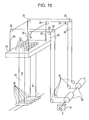
- As illustrated in
Fig. 15 , the vertical looper includes plural pairs of upper and lower rolls (upper looper rolls 33 and lower looper rolls 34). Thesteel sheet 30 runs while being wound alternately between the upper and lower rolls. Theupper looper rolls 33 are arranged at predetermined intervals on alooper carriage 32, with which theupper looper rolls 33 are horizontally suspended. Thelooper carriage 32 is coupled, at four corners thereof, by four respective chains orwire ropes 36 via sprockets orsheaves 35 to drive sprockets ordrums 38. Under control of acarriage driving mechanism 37, the drive sprockets ordrums 38 take up or let out the chains orwire ropes 36 as necessary, so that theupper looper rolls 33 are raised or lowered together with thelooper carriage 32. - In a conventional vertical looper, due to tilting of a looper carriage caused by variation in the amount of elongation among chains or wire ropes during operation, or due to unevenness in the shape of a steel sheet, the steel sheet may snake and this may prevent the operation. As a solution to this, the vertical looper has been operated under conditions where there is less occurrence of snaking. For example, the looper stroke (range of raising and lowering of the looper carriage) has been limited to reduce the occurrence of snaking. However, this has lowered the rate of capacity utilization. As another solution, snaking correction rolls may be installed in the vertical looper. However, the correction capability is limited, because the number of installable rolls is limited due to space limitations.
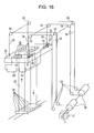
- Patent Literature 1 discloses a steel-sheet snaking preventing device for such a vertical looper. In this steel-sheet snaking preventing device for a vertical looper, as illustrated in
Fig. 16 , anedge position detector 42 detects a steel sheet edge on at least one of entry and exit sides of the vertical looper, and adisplacement gauge 43 computes the amount of snaking of asteel sheet 30. On the basis of the result of this computation, a control means 44 drives jackmechanism driving sources 46 to causejack mechanisms 41 to individually adjust the lengths of chains orwire ropes 36 that pull alooper carriage 32, so that thelooper carriage 32 is tilted in the direction of the steel sheet width to prevent snaking of the steel sheet in the vertical looper. - PTL 1: Japanese Unexamined Patent Application Publication No.
8-267139 - The steel-sheet snaking preventing device for a vertical looper disclosed in Patent Literature 1 has a problem in that it makes the facility complex. That is, the chains or wire ropes may be elongated and the amount of elongation is dependent on the length and the load. Therefore, in order to tilt the looper carriage to prevent snaking on the basis of the detected amount of snaking of the steel sheet, the length of adjustment of each chain or wire rope needs to be determined by taking into account the overall length of the chains or wire ropes (i.e., looper carriage height) and the amount of elongation produced by load (tension) at that time. This requires detectors and controllers for the task, and thus makes the facility complex and costly.
- Additionally, the conventional steel-sheet snaking preventing device for a vertical looper described above has a problem in that one-sided elongation of the steel sheet occurs when the looper stroke is short. A tensile stress σ applied to an end portion of the steel sheet by tilting the looper carriage can be expressed as σ = E·ε = E·(δ/L), where δ is an elongation at the end portion of the steel sheet, ε is an elongation strain, L is the steel sheet length between the upper and lower rolls, and E is the longitudinal elastic modulus of the steel sheet. If a value obtained by adding the unit tension UT of the steel sheet (which is obtained by dividing the steel sheet tension by the cross-sectional area of the steel sheet) to the tensile stress σ exceeds the yield point σy of the steel sheet (σy < σ+UT), one-sided elongation occurs due to plastic deformation of the end portion of the steel sheet. The smaller the steel sheet length L between the upper and lower rolls, the larger the tensile stress. Therefore, in a location where the looper stroke is short, it is necessary not only to tilt the looper carriage to prevent snaking, but also to tilt the looper carriage within a range where the one-sided elongation does not occur. However, one-sided elongation occurs in the conventional device, because the looper carriage is tilted on the basis only of the amount of snaking of the steel sheet.
- The present invention aims to solve the problems described above, and to provide a steel-sheet snaking preventing device and a steel-sheet snaking preventing method for a vertical looper that can prevent snaking of a steel sheet with a simple facility.
- The present invention for solving the problems described above is as follows.
- (1) A steel-sheet snaking preventing device for a vertical looper, the device including a jack mechanism provided at each of at least two corners of a looper carriage and coupled via a metal fitting to a chain or a wire rope that pulls the looper carriage; a tilt meter configured to detect the amount of tilt of the looper carriage; a level meter configured to detect a height of the looper carriage; and a means for receiving detection signals from the tilt meter and the level meter, determining the amount of tilt of the looper carriage at which the amount of snaking of a steel sheet becomes zero, sending the determined amount of tilt of the looper carriage as a command to the jack mechanism, and controlling the amount of tilt of the looper carriage by the jack mechanism.
- (2) A steel-sheet snaking preventing device for a vertical looper, the device including a jack mechanism provided at each of at least two corners of a looper carriage and coupled via a metal fitting to a chain or a wire rope that pulls the looper carriage; a tilt meter configured to detect the amount of tilt of the looper carriage; a snaking detector configured to detect the amount of snaking of a steel sheet in the looper; a level meter configured to detect a height of the looper carriage; and a means for receiving detection signals from the tilt meter, the snaking detector, and the level meter, sending the amount of raising or lowering of the corner of the looper carriage as a command to the jack mechanism, and controlling the amount of tilt of the looper carriage by the jack mechanism.
- (3) A steel-sheet snaking preventing method for a vertical looper, the method including, for preventing snaking of a steel sheet using the steel-sheet snaking preventing device for a vertical looper according to (2), determining the amount of tilt of the looper carriage such that the amount of tilt does not exceed the allowable amount of tilt at which one-sided elongation of the steel sheet does not occur, on the basis of a predetermined relationship between the amount of snaking of the steel sheet, the amount of tilt of the looper carriage, and the height of the looper carriage.
- In the steel-sheet snaking preventing device for a vertical looper according to the present invention, the snaking detector detects the amount of snaking of the steel sheet in the looper, and the level meter detects the height of the looper carriage. On the basis of the detection signals from the snaking detector and the level meter, the amount of raising or lowering of the corner of the looper carriage is determined by computation. On the basis of the result of this computation, the jack mechanism controls the amount of raising or lowering of the corner of the looper carriage such that the amount of snaking is within an allowable range. Thus, without varying the length of the chain or wire rope, it is possible to tilt the looper carriage in the direction of the steel sheet width and prevent snaking of the steel sheet in the looper with a simple facility. Also, by controlling the amount of raising or lowering of the corner of the looper carriage as described above, it is possible to minimize the tilt of the looper carriage and minimize a load applied to guide rolls and the like.
- In the steel-sheet snaking preventing device for a vertical looper according to the present invention, the tilt meter detects the amount of tilt of the looper carriage, and the level meter detects the height of the looper carriage. On the basis of the detection signals from the tilt meter and the level meter, the amount of tilt of the looper carriage at which the amount of snaking becomes zero is determined. A raising or lowering command is sent to the jack mechanism, and the amount of tilt of the looper carriage is controlled in accordance with the command by the jack mechanism. Therefore, it is not necessary to take into account the overall length of the chain or wire rope (height of the looper carriage) and the amount of elongation produced by load (tension), and it is possible to prevent snaking of the steel sheet in the looper with a simple facility.
- In the steel-sheet snaking preventing device for a vertical looper according to the present invention, the snaking detector detects the amount of snaking of the steel sheet in the looper, and the tilt meter detects the amount of tilt of the looper carriage. On the basis of the detection signals from the snaking detector and the tilt meter, a command to raise or lower the corner of the looper carriage is sent to the jack mechanism such that the amount of snaking is minimized, and the amount of tilt of the looper carriage is controlled in accordance with the command by the jack mechanism. Therefore, it is not necessary to take into account the overall length of the chain or wire rope (height of the looper carriage) and the amount of elongation produced by load (tension), and it is possible to prevent snaking of the steel sheet in the looper with a simple facility. Also, in this invention, the level meter detects the height of the looper carriage and, in accordance with the detection signal from the level meter, the amount of tilt of the looper carriage detected by the tilt meter is controlled within a range where an end portion of the steel sheet is not plastically deformed. Therefore, it is possible to prevent snaking without causing one-sided elongation of the steel sheet in a location where the looper stroke is short.
-
- [
Fig. 1] Fig. 1 is a perspective view illustrating a steel-sheet snaking preventing device for a wire rope type vertical looper according to the first invention. - [
Fig. 2] Fig. 2 shows a relationship between the amount of snaking and the amount of raising or lowering of a corner of a looper carriage according to the first invention. - [
Fig. 3] Fig. 3 is a vertical cross-sectional view illustrating how a steel sheet snakes when there is no tilt of the looper carriage according to the first invention. - [
Fig. 4] Fig. 4 is a vertical cross-sectional view illustrating a state where snaking of the steel sheet is corrected by the steel-sheet snaking preventing device for a vertical looper according to the first invention. - [
Fig. 5] Fig. 5 is a perspective view illustrating a steel-sheet snaking preventing device for a wire rope type vertical looper according to the second invention. - [
Fig. 6] Fig. 6 shows a relationship between the amount of snaking and the amount of tilt of a looper carriage according to the second invention. - [
Fig. 7] Fig. 7 is a cross-sectional view illustrating how a steel sheet snakes when there is no tilt of the looper carriage according to the second invention. - [
Fig. 8] Fig. 8 is a cross-sectional view illustrating a state where snaking of the steel sheet is corrected by the steel-sheet snaking preventing device for a vertical looper according to the second invention. - [
Fig. 9] Fig. 9 illustrates an allowable range of the amount of snaking in the vertical looper according to the second invention. - [
Fig. 10] Fig. 10 is a perspective view illustrating a steel-sheet snaking preventing device for a wire rope type vertical looper according to the third invention. - [
Fig. 11] Fig. 11 shows a relationship between the amount of snaking and the amount of tilt of a looper carriage according to the third invention. - [
Fig. 12] Fig. 12 shows a relationship between the looper carriage height Z and the allowable amount of tilt (the maximum value of the amount of tilt C at which one-sided elongation does not occur). - [
Fig. 13] Fig. 13 is a cross-sectional view illustrating how a steel sheet snakes when there is no tilt of the looper carriage according to the third invention. - [
Fig. 14] Fig. 14 is a cross-sectional view illustrating a state where snaking of the steel sheet is corrected by the steel-sheet snaking preventing device for a vertical looper according to the third invention. - [
Fig. 15] Fig. 15 is a perspective view illustrating a conventional wire rope type vertical looper. - [
Fig. 16] Fig. 16 is a perspective view illustrating a conventional steel-sheet snaking preventing device for a wire rope type vertical looper. - As a result of intensive studies, the present inventors have completed a first invention described below. The present inventors have further conducted intensive studies and completed a second invention. The present inventors have further conducted intensive studies and completed a third invention.
- A first invention of the present inventions will now be described. Means of the first invention are as follows.
- (1) A steel-sheet snaking preventing device for a vertical looper in a steel-sheet continuous processing facility, the device including a jack mechanism provided at each of two corners on one side of a looper carriage in a steel sheet width direction and coupled via a metal fitting to a chain or a wire rope that pulls the looper carriage; a snaking detector configured to detect the amount of snaking of a steel sheet in the looper; a level meter configured to detect a height of the looper carriage; and a means for receiving detection signals from the snaking detector and the level meter, determining the amount of raising or lowering of the corner of the looper carriage by computation, sending the determined amount of raising or lowering as a command to the jack mechanism, and controlling the amount of raising or lowering of the corner of the looper carriage by the jack mechanism.
- (2) A steel-sheet snaking preventing method for a vertical looper, the method including, for preventing snaking of a steel sheet using the steel-sheet snaking preventing device for a vertical looper according to (1), determining the amount of raising or lowering of the corner of the looper carriage on the basis of the amount of snaking of the steel sheet and the height of the looper carriage.
- (3) The steel-sheet snaking preventing method for a vertical looper according to (2), wherein a relationship between the amount of snaking of the steel sheet, the height position of the looper carriage, and the amount of raising or lowering of the corner of the looper carriage is determined, and the amount of raising or lowering of the corner of the looper carriage is determined using the determined relationship.
- In the first invention, each of two corners on one side of a looper carriage in the steel sheet width direction is provided with a jack mechanism that is coupled via a metal fitting to a chain or a wire rope that pulls the looper carriage. A snaking detector detects the amount of snaking of a steel sheet in the looper, and sends the detection signal to a control means. On the basis of the detection signal, from a relationship between the amount of snaking and the amount of raising or lowering of the corner of the looper carriage, the control means calculates the amount of raising or lowering of the jack mechanism at each corner of the looper carriage such that the amount of snaking is within an allowable range. The relationship between the amount of snaking and the amount of raising or lowering of the corner of the looper carriage varies depending on the height of the looper carriage. Therefore, the relationship between the amount of snaking and the amount of raising or lowering of the corner of the looper carriage is determined in advance in relation to the height of the looper carriage. Next, the snaking detector detects the amount of snaking of the steel sheet in the looper, and the level meter detects the height of the looper carriage. On the basis of the resulting detection signals and the relationship between the amount of snaking and the amount of raising or lowering of the corner of the looper carriage, the amount of raising or lowering B of the corner of the looper carriage (the amount of raising or lowering of the jack mechanism) is calculated such that the amount of snaking is within an allowable range. When the jack mechanism receives the amount of raising or lowering sent as a command signal from the control means, a driving source of the jack mechanism rotates a horizontal axis worm, which rotates a worm gear about a vertical axis. A vertical axis jack rotating together with the worm gear is raised or lowered with respect to the metal fitting. This facilitates correction of the tilt of the looper carriage in the steel sheet width direction and makes it possible to prevent snaking.
- A concrete description of the first invention will now be given.
Fig. 1 is a perspective view illustrating a steel-sheet snaking preventing device for a wire rope type vertical looper according to an embodiment of the first invention. - In
Fig. 1 ,reference numeral 30 denotes a steel sheet,reference numeral 32 denotes a looper carriage,reference numeral 33 denotes an upper looper roll,reference numeral 34 denotes a lower looper roll,reference numeral 35 denotes a sheave,reference numeral 36 denotes a wire rope,reference numeral 37 denotes a carriage driving mechanism,reference numeral 38 denotes a drum,reference numeral 40 denotes a metal fitting,reference numeral 41 denotes a jack mechanism, andreference numeral 46 denotes a jack mechanism driving source.Reference numeral 2 denotes a control means (controller),reference numeral 3 denotes a level meter, and reference numeral 4 denotes a snaking detector. Thelevel meter 3 may be of any type as long as it is capable of calculating a carriage height. Thelevel meter 3 detects the amount of rotation by means of a rotation detector (so-called PLG or encoder) attached to an end of a drum shaft, and calculates the carriage height. - In the present device, at each of two corners on one side of the
looper carriage 32 in the steel sheet width direction, thejack mechanism 41 is coupled via the metal fitting 40 to thewire rope 36 that pulls thelooper carriage 32. - The relationship between the amount of snaking and the amount of raising or lowering of each corner of the looper carriage varies depending on the looper carriage height. Therefore, from tests in the actual facility and analysis of operating conditions, the relationship between the amount of snaking and the amount of raising or lowering of the corner of the looper carriage is determined in relation to the looper carriage height.
Fig. 2 shows an exemplary relationship between the amount of snaking A and the amount of raising or lowering B of the corner of the looper carriage determined in relation to the looper carriage height Z when, in an entry-side looper in a steel-sheet continuous processing facility, a steel sheet with a thickness of 0.7 mm and a width of 1880 mm was passed through the looper carriage having no tilt and the amount of raising or lowering of the corner of the looper carriage was varied during occurrence of snaking. The carriage height Z is represented by its ratio (%) to the maximum height defined in the facility specification. The amount of snaking inFig. 2 is the amount of rightward snaking along the X-axis inFig. 1 . The amount of raising or lowering of the corner of the looper carriage inFig. 2 is the amount of upward movement of the corner of the looper carriage. -
Fig. 2 shows that, for example, when Z = 90%, the amount of snaking can be reduced from about 225 mm to about 100 mm by raising the corner of the looper carriage by about 20 mm. The amount of snaking can be reduced to zero by further raising the corner of the looper carriage by about 15 mm (i.e., 35 mm in total). Also, when Z = 60%, the amount of snaking can be reduced from 150 mm to about 100 mm by raising the corner of the looper carriage by about 12 mm. The amount of snaking can be reduced to zero by further raising the corner of the looper carriage by about 23 mm (i.e., 35 mm in total). - For each steel sheet size, the relationship between the amount of snaking A and the amount of raising or lowering B of the corner of the looper carriage is stored, in the control means 2, in association with various looper carriage heights Z. An allowable range of the amount of snaking is also input and stored in the control means 2.
- Typically, the looper includes a roll-out sensor for preventing the steel sheet from running off the roll. The allowable range of the amount of snaking in the looper is determined by the position of the roll-out sensor provided for preventing the steel sheet from running off the roll. For example, when the roll width W = 2200 mm, the sheet width b = 1880 mm, and the sensor position (distance from a roll end) x = 60 mm, the allowable range is set to (W-b)/2-x = 100 mm.
- In the present device, the snaking detector 4 detects the amount of snaking A of the
steel sheet 30 in the looper and sends the detection signal to the control means 2. Also, thelevel meter 3 detects the looper carriage height Z and sends the detection signal to the control means 2. - On the basis of the sent detection signal representing the amount of snaking and the sent detection signal representing the looper carriage height, and using the stored relationship between the amount of snaking A, the looper carriage height Z, and the amount of raising or lowering B of the corner of the looper carriage, the control means 2 calculates the amount of raising or lowering B of the corner of the looper carriage, that is, the amount of raising or lowering of the
jack mechanism 41 at which the amount of snaking A is within the allowable range. - The control means 2 sends the calculated amount of raising or lowering as a command signal to the
jack mechanism 41. When thejack mechanism 41 receives the command signal from the control means 2, a driving source of thejack mechanism 41 rotates a horizontal axis worm, which rotates a worm gear about a vertical axis. A vertical axis jack rotating together with the worm gear is raised or lowered with respect to the metal fitting 40 to tilt the looper carriage in the steel sheet width direction, so that snaking can be prevented. It is also possible to prevent snaking caused by the shape of the steel sheet itself and occurring when thelooper carriage 32 originally has no tilt. Since the looper carriage can be tilted in the steel sheet width direction without varying the length of the chain or wire rope, it is possible to simplify the facility. - Since the
looper carriage 32 is typically raised or lowered in a horizontal state, a given amount of clearance E (seeFig. 3 ) is provided between eachguide rail 51 and guide rolls 50. A steady load is not applied to the guide rolls 50 when thelooper carriage 32 has no tilt. However, when thelooper carriage 32 has a tilt, the clearance E disappears and a steady load is applied to the guide rolls 50. As the tilt increases, the load also increases. As a result, the life of the guide rolls 50 is shortened. - In the first invention, the amount of raising or lowering of the corner of the looper carriage is controlled, on the basis of the detection signal (the amount of snaking) from the snaking detector 4 and the detection signal from the
level meter 3, such that the amount of snaking is within the allowable range. Therefore, as illustrated inFig. 4 , the tilt of thelooper carriage 32 can be minimized and the load applied to the guide rolls 50 can also be minimized. This can increase the life of the guide rolls. Also, it is possible to prevent abrasion powders of the guide rolls from falling and adhering to the steel sheet. - The steel-sheet snaking preventing device for a wire rope type vertical looper has been described in the foregoing embodiment. It is obvious that the first invention is also applicable to a chain type vertical looper. In the chain type vertical looper, sprockets are used instead of sheaves, and drive sprockets are used instead of drums.
- The second invention will now be described. In the steel-sheet snaking preventing device for a vertical looper according to the second invention, a tilt meter detects the amount of tilt of a looper carriage and sends the detection signal to a control means. On the basis of the detection signal, the control means calculates the amount of tilt of the looper carriage at which the amount of snaking becomes zero, from a predetermined relationship between the amount of snaking of a steel sheet and the amount of tilt of the looper carriage. The relationship between the amount of snaking of the steel sheet and the amount of tilt of the looper carriage varies depending on the looper carriage height. Therefore, a level meter detects the looper carriage height and, in accordance with the detection signal from the level meter, the amount of tilt of the looper carriage at which the amount of snaking becomes zero is calculated. The control means compares the detected amount of tilt of the looper carriage with the calculated amount of tilt of the looper carriage at which the amount of snaking becomes zero. Then, if there is a difference therebetween, the control means sends a raising or lowering command to each jack mechanism. When the jack mechanism receives the command signal from the control means, a driving source of the jack mechanism rotates a horizontal axis worm, which rotates a worm gear about a vertical axis. A vertical axis jack rotating together with the worm gear is raised or lowered with respect to a metal fitting to correct the amount of tilt of the looper carriage. When the detected amount of tilt of the looper carriage becomes equal to the calculated amount of tilt of the looper carriage at which the amount of snaking becomes zero, the control means sends a stop command to the jack mechanism. As a result, the amount of tilt of the looper carriage is set to a value at which the amount of snaking becomes zero, so that snaking can be prevented.
- A concrete description of the second invention will now be given.
Fig. 5 is a perspective view illustrating a steel-sheet snaking preventing device for a wire rope type vertical looper according to an embodiment of the second invention. - In
Fig. 5 ,reference numeral 30 denotes a steel sheet,reference numeral 32 denotes a looper carriage,reference numeral 33 denotes an upper looper roll,reference numeral 34 denotes a lower looper roll,reference numeral 35 denotes a sheave,reference numeral 36 denotes a wire rope,reference numeral 37 denotes a carriage driving mechanism,reference numeral 38 denotes a drum,reference numeral 40 denotes a metal fitting,reference numeral 41 denotes a jack mechanism, andreference numeral 46 denotes a jack mechanism driving source. Reference numeral 1 denotes a tilt meter,reference numeral 2 denotes a control means (controller), andreference numeral 3 denotes a level meter. The tilt meter 1 may be of any type as long as it is capable of measuring a tilt. The tilt meter 1 used here is one that uses a pendulum, performs servo control such that the pendulum is in the center of a magnetic sensor, and calculates the amount of tilt from the amount of servo control (current output). Thelevel meter 3 may be of any type as long as it is capable of calculating the carriage height. Thelevel meter 3 detects the amount of rotation by means of a rotation detector (so-called PLG or encoder) attached to an end of a drum shaft, and calculates the carriage height. - In the present device, at each of two corners on one side of the
looper carriage 32 in the steel sheet width direction (i.e., at each of at least two corners of the looper carriage), thejack mechanism 41 is coupled via the metal fitting 40 to thewire rope 36 that pulls thelooper carriage 32. - The relationship between the amount of snaking and the amount of tilt of the looper carriage varies depending on the looper carriage height. Therefore, from tests in the actual facility and analysis of operating conditions, the relationship is determined in advance in relation to the looper carriage height.
Fig. 6 shows an exemplary relationship between the amount of snaking A and the amount of tilt C of the looper carriage determined in relation to the looper carriage height Z when, in an entry-side looper in a steel-sheet continuous processing facility, a steel sheet with a thickness of 1.2 mm and a width of 1781 mm was passed through the looper carriage having no tilt and the amount of tilt of the looper carriage was varied during occurrence of snaking. The amount of snaking was measured by a CPC sensor 4 that detects the position of the steel sheet in the width direction. The looper carriage height Z is represented by its ratio (%) to the maximum height defined in the facility specification. The amount of snaking inFig. 6 is the amount of rightward snaking along the X-axis inFig. 5 . As illustrated inFig. 8 , the amount of tilt of the looper carriage is the amount of raising of the right side bearing of the upper looper roll 33 with respect to the left side bearing. - Since the
looper carriage 32 is typically raised or lowered in a horizontal state, a given amount of clearance E (seeFig. 7 ) is provided between eachguide rail 51 and guide rolls 50. - In the second invention, the amount of tilt of the looper carriage at which the amount of snaking becomes zero is controlled on the basis of the detection signal from the tilt meter 1 and the detection signal from the level meter 3 (see
Fig. 8 ). -
Fig. 6 shows that, for example, when Z = 70%, the amount of snaking can be reduced from about 125 mm to about 35 mm by raising the right side bearing of the upper looper roll by about 12 mm. The amount of snaking can be reduced to zero by further raising the right side bearing of the upper looper roll by about 4.5 mm (i.e., 16.5 mm in total). Also, when Z = 30%, the amount of snaking can be reduced from about 90 mm to about 30 mm by raising the right side bearing of the upper looper roll by about 4 mm. The amount of snaking can be reduced to zero by further raising the right side bearing of the upper looper roll by about 2 mm (i.e., 6 mm in total). - For each steel sheet size, the relationship between the amount of snaking A and the amount of tilt C of the looper carriage is stored, in the control means 2, in association with various looper carriage heights Z. An allowable range of the amount of snaking is also input and stored in the control means 2.
- Typically, the looper includes a roll-out sensor for preventing the steel sheet from running off the roll. The allowable range of the amount of snaking in the looper is determined by the position of the roll-out sensor provided for preventing the steel sheet from running off the roll. For example, when the roll width W = 2200 mm, the sheet width b = 1880 mm, and the sensor position (distance from a roll end) x = 60 mm, the allowable range is set to (W-b)/2-x = 100 mm (see
Fig. 9 ). - In the present device, the tilt meter 1 detects the amount of tilt of the
looper carriage 32 and sends the detection signal to the control means 2. On the basis of the detection signal, the control means 2 calculates, from the relationship between the amount of snaking and the amount of tilt of thelooper carriage 32, the amount of tilt of thelooper carriage 32 at which the amount of snaking becomes zero. The relationship between the amount of snaking and the amount of tilt of thelooper carriage 32 varies depending on the height of thelooper carriage 32. Therefore, thelevel meter 3 detects the height of thelooper carriage 32. Then, in accordance with the detection signal from the level meter, the amount of tilt of thelooper carriage 32 at which the amount of snaking becomes zero is calculated in advance in relation to the height of thelooper carriage 32, from tests in the actual facility and analysis of operating conditions. - The control means 2 compares the detected amount of tilt of the
looper carriage 32 with the calculated amount of tilt of thelooper carriage 32 at which the amount of snaking becomes zero. Then, if there is a difference therebetween, the control means 2 sends a raising or lowering command to eachjack mechanism 41. When thejack mechanism 41 receives the command signal from the control means, the jackmechanism driving source 46 rotates a horizontal axis worm, which rotates a worm gear about a vertical axis. A vertical axis jack rotating together with the worm gear is raised or lowered with respect to the metal fitting 40 to correct the amount of tilt of thelooper carriage 32. When the detected amount of tilt of thelooper carriage 32 becomes equal to the calculated amount of tilt of thelooper carriage 32 at which the amount of snaking becomes zero, the control means 2 sends a stop command to thejack mechanism 41. As a result, the amount of tilt of thelooper carriage 32 is set to a value at which the amount of snaking becomes zero, so that snaking can be prevented. From tests in the actual facility and analysis of operating conditions, the amount of tilt of thelooper carriage 32 at which the amount of snaking becomes zero is calculated in advance in relation to the height of thelooper carriage 32. Thus, it is also possible to prevent snaking caused by the shape of the steel sheet itself and occurring when thelooper carriage 32 originally has no tilt. Since the looper carriage can be tilted in the steel sheet width direction without varying the length of the chain or wire rope, it is possible to simplify the facility. - A steel-sheet snaking preventing device for a wire rope type vertical looper has been described in the foregoing embodiment. It is obvious that the second invention is also applicable to a chain type vertical looper. In the chain type vertical looper, sprockets are used instead of sheaves, and drive sprockets are used instead of drums.
- The third invention will now be described. In the steel-sheet snaking preventing device for a vertical looper according to the third invention, a snaking detector detects the amount of snaking of a steel sheet in the looper, a tilt meter detects the amount of tilt of a looper carriage, and the resulting detection signals are sent to a control means. On the basis of the detection signals, the control means sends a command to correct the amount of raising or lowering to a jack mechanism at each corner of the carriage so as to minimize the amount of snaking of the steel sheet. When the jack mechanism receives the command signal from the control means, a jack mechanism driving source rotates a horizontal axis worm, which rotates a worm gear about a vertical axis. A vertical axis jack rotating together with the worm gear is raised or lowered with respect to a metal fitting to vary the amount of tilt of the looper carriage through each chain or wire rope that pulls the looper carriage.
- For the amount of tilt of the looper carriage, depending on the looper carriage height, there is an allowable amount of tilt at which one-sided elongation of the steel sheet does not occur. Therefore, a level meter detects the looper carriage height. Then, in accordance with the detection signal from the level meter, if the amount of tilt of the looper carriage reaches the allowable amount of tilt at which one-sided elongation of the steel sheet does not occur, the command sent to each jack mechanism to correct the amount of raising or lowering is stopped, and the tilting of the looper carriage is stopped. Therefore, even in a location where the looper stroke is short, it is possible to prevent snaking without one-sided elongation of the steel sheet caused by the tilt of the looper carriage.
- A concrete description of the third invention will now be given.
Fig. 10 is a perspective view illustrating a steel-sheet snaking preventing device for a wire rope type vertical looper according to an embodiment of the third invention. - In
Fig. 10 ,reference numeral 30 denotes a steel sheet,reference numeral 32 denotes a looper carriage,reference numeral 33 denotes an upper looper roll,reference numeral 34 denotes a lower looper roll,reference numeral 35 denotes a sheave,reference numeral 36 denotes a wire rope,reference numeral 37 denotes a carriage driving mechanism,reference numeral 38 denotes a drum,reference numeral 40 denotes a metal fitting,reference numeral 41 denotes a jack mechanism, andreference numeral 46 denotes a jack mechanism driving source. Reference numeral 1 denotes a tilt meter,reference numeral 2 denotes a control means (controller),reference numeral 3 denotes a level meter, and reference numeral 4 denotes a snaking detector (CPC sensor). The tilt meter 1 may be of any type as long as it is capable of measuring a tilt. The tilt meter 1 used here is one that uses a pendulum, performs servo control such that the pendulum is in the center of a magnetic sensor, and calculates the amount of tilt from the amount of servo control (current output). Thelevel meter 3 may be of any type as long as it is capable of calculating the carriage height. Thelevel meter 3 detects the amount of rotation by means of a rotation detector (so-called PLG or encoder) attached to an end of a drum shaft, and calculates the carriage height. - In the present device, at each of two corners on one side of the
looper carriage 32 in the steel sheet width direction (i.e., at each of at least two corners of the looper carriage), thejack mechanism 41 is coupled via the metal fitting 40 to thewire rope 36 that pulls thelooper carriage 32. - The relationship between the amount of tilt of the looper carriage and the amount of snaking varies depending on the looper carriage height. Therefore, from tests in the actual facility and analysis of operating conditions, the relationship between the amount of tilt of the looper carriage and the amount of snaking is determined in advance in relation to the looper carriage height.
Fig. 11 shows an exemplary relationship between the amount of snaking A and the amount of tilt C of the looper carriage determined in relation to the looper carriage height Z when, in an entry-side looper in a steel-sheet continuous processing facility, a steel sheet (mild steel) with a thickness of 0.8 mm and a width of 1880 mm was passed through thelooper carriage 32 having no tilt (seeFig. 13 ) and the looper carriage height was varied during occurrence of snaking. The amount of snaking was measured by a CPC sensor (snaking detector 4) that detects the position of the steel sheet in the width direction. The looper carriage height Z is represented by its ratio (%) to the maximum height defined in the facility specification. The amount of snaking inFig. 11 is the amount of rightward snaking along the X-axis inFig. 10 . As illustrated inFig. 14 , the amount of tilt of the looper carriage is the amount of raising of the right side bearing of the upper looper roll 33 with respect to the left side bearing. - The allowable amount of tilt at which one-sided elongation of the steel sheet does not occur varies depending on the looper carriage height. Therefore, from tests in the actual facility and analysis of operating conditions, the allowable amount of tilt at which one-sided elongation of the steel sheet does not occur is determined in advance in relation to the looper carriage height.
Fig. 12 shows an exemplary relationship between the looper carriage height Z and the allowable amount of tilt (the maximum amount of tilt C at which one-sided elongation does not occur) determined when, in an entry-side looper in a steel-sheet continuous processing facility, a steel sheet (mild steel) with a thickness of 0.8 mm and a width of 1880 mm was passed through thelooper carriage 32 having no tilt. A tensile stress σ (N/mm2) applied to an end portion of the steel sheet by tilting the looper carriage can be expressed as σ = E·ε = E·(δ/L), where δ (mm) is an elongation at the end portion of the steel sheet, ε is an elongation strain, L (mm) is the steel sheet length between the upper and lower rolls, and E (N/mm2) is the longitudinal elastic modulus of the steel sheet. If a value obtained by adding the unit tension UT of the steel sheet (which is obtained by dividing the steel sheet tension by the cross-sectional area of the steel sheet) to the tensile stress σ exceeds the yield point σy of the steel sheet (σy < σ+UT), the end portion of the steel sheet is plastically deformed and this causes one-sided elongation. The amount of tilt C is expressed as δxD/E, where D is the distance between bearings. Thus, the relationship between the looper carriage height Z and the allowable amount of tilt (the maximum amount of tilt C at which one-sided elongation does not occur) shown inFig. 12 is obtained. For example, when Z = 90%, the allowable amount of tilt is 40 mm, and when Z = 30%, the allowable amount of tilt is 18 mm. - In the third invention, on the basis of the detection signal from the tilt meter 1 and the detection signal from the snaking detector 4, the amount of tilt C of the looper carriage at which the amount of snaking is minimized is controlled by the amount of raising or lowering B of the jack mechanism 41 (see
Fig. 14 ). - For each size, the relationship between the amount of tilt of the looper carriage and the amount of snaking is stored, in the control means 2, in association with various looper carriage heights Z. An allowable amount of tilt at which one-sided elongation of the steel sheet does not occur (the maximum amount of tilt C at which one-sided elongation does not occur) is also input and stored in the control means 2.
- In the present device, the tilt meter 1 detects the amount of tilt C of the
looper carriage 32, and the snaking detector 4 detects the amount of snaking A of thesteel sheet 30 in the looper. Next, the detection signals from the tilt meter 1 and the snaking detector 4 are sent to the control means 2. On the basis of the detection signals, the control means 2 calculates the amount of tilt of the looper carriage at which the amount of snaking of the steel sheet is minimized. The amount of tilt of the looper carriage at which the amount of snaking of the steel sheet is minimized is calculated in advance in relation to the height of thelooper carriage 32. - At this point, the
level meter 3 detects the looper carriage height. In accordance with the detection signal from thelevel meter 3, the control means 2 compares the amount of tilt of the looper carriage detected by the tilt meter 1 with the allowable amount of tilt at which one-sided elongation of the steel sheet does not occur. On the basis of the comparison, the control means 2 sends a raising or lowering command to thejack mechanism 41 at each corner of the looper carriage such that, for example, the amount of snaking of the steel sheet is minimized, that is, such that the amount of tilt of the looper carriage detected by the tilt meter 1 becomes equal to the allowable amount of tilt at which one-sided elongation of the steel sheet does not occur. When thejack mechanism 41 receives the command signal from the control means 2, the jackmechanism driving source 46 rotates a horizontal axis worm, which rotates a worm gear about a vertical axis. A vertical axis jack rotating together with the worm gear is raised or lowered with respect to the metal fitting 40 to vary the amount of tilt of thelooper carriage 32. When the amount of tilt of the looper carriage reaches the allowable amount of tilt at which one-sided elongation of the steel sheet does not occur, the control means 2 stops the raising or lowering command for thejack mechanisms 41. As a result, the tilting of thelooper carriage 32 is stopped. Thus, even in a location where the looper stroke is short, it is possible to prevent snaking without one-sided elongation of the steel sheet caused by the tilt of the looper carriage. Since the looper carriage can be tilted in the steel sheet width direction without varying the length of the chain or wire rope, it is possible to simplify the facility. - A steel-sheet snaking preventing device for a wire rope type vertical looper has been described in the foregoing embodiment. It is obvious that the third invention is also applicable to a chain type vertical looper. In the chain type vertical looper, sprockets are used instead of sheaves, and drive sprockets are used instead of drums.
- In the vertical looper described in the present embodiment, the allowable range of the amount of snaking is 100 mm or less. In this vertical looper, when the looper carriage is not tilted (
Fig. 3 ) and the looper carriage height Z is 60%, the amount of snaking A of the steel sheet having an uneven end shape is 150 mm. The conventional device (Fig. 15 ), which is unable to reduce the amount of snaking, needs to be used with the looper carriage height Z restricted, so as to prevent the steel sheet from running off theupper looper roll 33. - On the other hand, in the device according to the first invention, when the looper carriage height Z is 90%, the amount of snaking can be made 100 mm or less if the amount of raising or lowering B of the corner of the looper carriage is 20 mm. When the looper carriage height Z is 60%, the amount of snaking can be made 100 mm or less if the amount of raising or lowering B of the corner of the looper carriage is 12 mm. When the looper carriage height Z is 30%, there is no need to adjust the amount of raising or lowering of the corner of the looper carriage.
- In the device according to the first invention, if the amount of raising or lowering B of the corner of the looper carriage is 35 mm, the amount of snaking is 0 mm and a good snaking preventing effect is achieved even when the looper carriage height Z is 90%.
- In the vertical looper described in the present embodiment, when the looper carriage is not tilted (
Fig. 7 ) and the looper carriage height Z is 70%, the amount of snaking A of the steel sheet having an uneven end shape is 125 mm, which is measured by the CPC sensor. Since the amount of snaking cannot be reduced by the conventional technique, the looper carriage height Z needs to be restricted to prevent the steel sheet from running off theupper looper roll 33. - In the device according to the second invention, when the amount of tilt C of the looper carriage is 16.5 mm, the amount of snaking A is 0 mm and a good result can be obtained.
- In the vertical looper described in the present embodiment, when the looper carriage is not tilted (
Fig. 13 ) and the looper carriage height Z is 30%, the amount of snaking A of the steel sheet having an uneven end shape is 90 mm, which is measured by the CPC sensor. In the conventional technique, when the amount of tilt of the looper carriage is 19 mm or more, one-sided elongation of the steel sheet occurs even though the amount of snaking can be reduced. - In the device according to the third invention, as shown in
Fig. 12 , when Z = 30% and the amount of tilt of the looper carriage is less than 18 mm, which is the allowable amount of tilt, the amount of snaking can be reduced from 90 mm and a good result can be achieved without causing one-sided elongation of the steel sheet. -
- 1:
- tilt meter
- 2:
- control means
- 3:
- level meter
- 4:
- snaking detector (CPC sensor)
- 30:
- steel sheet
- 32:
- looper carriage
- 33:
- upper looper roll
- 34:
- lower looper roll
- 35:
- sprocket or sheave
- 36:
- chain or wire rope
- 37:
- carriage driving mechanism
- 38:
- drive sprocket or drum
- 40:
- metal fitting
- 41:
- jack mechanism
- 42:
- edge position detector
- 43:
- displacement gauge
- 44:
- control means
- 46:
- jack mechanism driving source
- 50:
- guide roll
- 51:
- guide rail
- Z:
- carriage height
- A:
- amount of snaking
- B:
- amount of raising or lowering
- C:
- amount of tilt of a looper carriage
- D:
- distance between bearings
- E:
- clearance
Claims (3)
- A steel-sheet snaking preventing device for a vertical looper, the device comprising a jack mechanism provided at each of at least two corners of a looper carriage and coupled via a metal fitting to a chain or a wire rope that pulls the looper carriage; a tilt meter configured to detect the amount of tilt of the looper carriage; a level meter configured to detect a height of the looper carriage; and a means for receiving detection signals from the tilt meter and the level meter, determining the amount of tilt of the looper carriage at which the amount of snaking of a steel sheet becomes zero, sending the determined amount of tilt of the looper carriage as a command to the jack mechanism, and controlling the amount of tilt of the looper carriage by the jack mechanism.
- A steel-sheet snaking preventing device for a vertical looper, the device comprising a jack mechanism provided at each of at least two corners of a looper carriage and coupled via a metal fitting to a chain or a wire rope that pulls the looper carriage; a tilt meter configured to detect the amount of tilt of the looper carriage; a snaking detector configured to detect the amount of snaking of a steel sheet in the looper; a level meter configured to detect a height of the looper carriage; and a means for receiving detection signals from the tilt meter, the snaking detector, and the level meter, sending the amount of raising or lowering of the corner of the looper carriage as a command to the jack mechanism, and controlling the amount of tilt of the looper carriage by the jack mechanism.
- A steel-sheet snaking preventing method for a vertical looper, the method comprising, for preventing snaking of a steel sheet using the steel-sheet snaking preventing device for a vertical looper according to Claim 2, determining the amount of tilt of the looper carriage such that the amount of tilt does not exceed the allowable amount of tilt at which one-sided elongation of the steel sheet does not occur, on the basis of a predetermined relationship between the amount of snaking of the steel sheet, the amount of tilt of the looper carriage, and the height of the looper carriage.
Applications Claiming Priority (3)
| Application Number | Priority Date | Filing Date | Title |
|---|---|---|---|
| JP2012270862A JP5494789B1 (en) | 2012-12-12 | 2012-12-12 | Steel loop meander prevention device for vertical looper |
| JP2013171835A JP5494875B1 (en) | 2013-08-22 | 2013-08-22 | Steel plate meandering prevention device for vertical looper and method for preventing meandering of steel plate |
| PCT/JP2013/005225 WO2014091642A1 (en) | 2012-12-12 | 2013-09-04 | Device for preventing steel plate meandering in vertical looper and method for preventing meandering of steel plate |
Publications (3)
| Publication Number | Publication Date |
|---|---|
| EP2933032A1 true EP2933032A1 (en) | 2015-10-21 |
| EP2933032A4 EP2933032A4 (en) | 2016-03-16 |
| EP2933032B1 EP2933032B1 (en) | 2019-07-17 |
Family
ID=50933957
Family Applications (1)
| Application Number | Title | Priority Date | Filing Date |
|---|---|---|---|
| EP13862224.6A Active EP2933032B1 (en) | 2012-12-12 | 2013-09-04 | Device for preventing steel plate meandering in vertical looper and method for preventing meandering of steel plate |
Country Status (6)
| Country | Link |
|---|---|
| US (1) | US9855590B2 (en) |
| EP (1) | EP2933032B1 (en) |
| KR (1) | KR101750639B1 (en) |
| CN (1) | CN104853860B (en) |
| TW (1) | TWI541484B (en) |
| WO (1) | WO2014091642A1 (en) |
Cited By (2)
| Publication number | Priority date | Publication date | Assignee | Title |
|---|---|---|---|---|
| WO2017158214A1 (en) * | 2016-03-15 | 2017-09-21 | Torres Martinez M | Oven for the thermal treatment of filaments |
| EP3858770A4 (en) * | 2018-11-02 | 2021-08-04 | JFE Steel Corporation | Bridle device, method for controlling snaking of steel band, and method for producing steel band |
Families Citing this family (4)
| Publication number | Priority date | Publication date | Assignee | Title |
|---|---|---|---|---|
| CN106081692B (en) * | 2016-08-08 | 2017-11-17 | 青岛新大成塑料机械有限公司 | Drip irrigation zone storage band device and its storage band method |
| KR102105527B1 (en) * | 2017-12-26 | 2020-04-28 | 주식회사 포스코 | Device for preventing strip meandering in looping tower of annealing line |
| JP6814323B1 (en) * | 2020-09-09 | 2021-01-13 | 中外炉工業株式会社 | Vertical looper carriage horizontal maintenance device |
| JP6988982B1 (en) * | 2020-10-29 | 2022-01-05 | Jfeスチール株式会社 | Meandering amount detection method and meandering control method for metal strips |
Family Cites Families (15)
| Publication number | Priority date | Publication date | Assignee | Title |
|---|---|---|---|---|
| JPH0293017U (en) * | 1989-01-11 | 1990-07-24 | ||
| JPH0730168Y2 (en) * | 1989-03-31 | 1995-07-12 | 川崎製鉄株式会社 | Vertical looper equipment |
| US5172579A (en) * | 1989-07-31 | 1992-12-22 | Kabushiki Kaisha Toshiba | Steering control apparatus for rolled plates |
| JPH0824957B2 (en) * | 1991-05-14 | 1996-03-13 | 日本鋼管株式会社 | Looper carriage leveling device |
| JP3079172B2 (en) * | 1992-03-17 | 2000-08-21 | 東洋鋼鈑株式会社 | Vertical looper |
| JPH05329523A (en) * | 1992-05-27 | 1993-12-14 | Kawasaki Steel Corp | Method for measuring inclination of vertical looper carriage |
| JPH073809U (en) * | 1993-06-25 | 1995-01-20 | 住友金属工業株式会社 | Steel strip meandering correction device |
| JPH08168819A (en) * | 1994-12-19 | 1996-07-02 | Nkk Corp | Vertical looper steel plate meandering prevention device |
| JP3308757B2 (en) | 1995-03-29 | 2002-07-29 | 川崎製鉄株式会社 | Meandering correction method and device for metal strip |
| JPH09328246A (en) * | 1996-06-13 | 1997-12-22 | Shikoku Kakoki Co Ltd | Web accumulator |
| JP3682950B2 (en) * | 2000-05-19 | 2005-08-17 | Jfe電制株式会社 | Inclination measuring device for vertical looper carriage |
| TWI319720B (en) * | 2007-04-16 | 2010-01-21 | Conveyor for substrate material | |
| JP5656596B2 (en) * | 2010-12-08 | 2015-01-21 | キヤノン株式会社 | Sheet feeding apparatus and image forming apparatus |
| JP5760629B2 (en) * | 2011-04-15 | 2015-08-12 | Jfeスチール株式会社 | How to correct meandering of steel strip |
| JP5910178B2 (en) * | 2012-03-06 | 2016-04-27 | Jfeスチール株式会社 | Steel plate meandering prevention device for vertical looper and method for preventing meandering of steel plate |
-
2013
- 2013-09-04 WO PCT/JP2013/005225 patent/WO2014091642A1/en not_active Ceased
- 2013-09-04 EP EP13862224.6A patent/EP2933032B1/en active Active
- 2013-09-04 US US14/648,756 patent/US9855590B2/en active Active
- 2013-09-04 CN CN201380065122.2A patent/CN104853860B/en active Active
- 2013-09-04 KR KR1020157014876A patent/KR101750639B1/en active Active
- 2013-09-05 TW TW102132021A patent/TWI541484B/en active
Cited By (4)
| Publication number | Priority date | Publication date | Assignee | Title |
|---|---|---|---|---|
| WO2017158214A1 (en) * | 2016-03-15 | 2017-09-21 | Torres Martinez M | Oven for the thermal treatment of filaments |
| US10895021B2 (en) | 2016-03-15 | 2021-01-19 | Manuel Torres Martinez | Oven for the thermal treatment of filaments |
| EP3858770A4 (en) * | 2018-11-02 | 2021-08-04 | JFE Steel Corporation | Bridle device, method for controlling snaking of steel band, and method for producing steel band |
| US11673174B2 (en) | 2018-11-02 | 2023-06-13 | Jfe Steel Corporation | Bridle device, method for controlling snaking of steel strip, and method for producing steel strip |
Also Published As
| Publication number | Publication date |
|---|---|
| TWI541484B (en) | 2016-07-11 |
| CN104853860B (en) | 2016-12-14 |
| EP2933032A4 (en) | 2016-03-16 |
| US20150306649A1 (en) | 2015-10-29 |
| CN104853860A (en) | 2015-08-19 |
| WO2014091642A1 (en) | 2014-06-19 |
| EP2933032B1 (en) | 2019-07-17 |
| TW201423014A (en) | 2014-06-16 |
| KR101750639B1 (en) | 2017-06-23 |
| KR20150081355A (en) | 2015-07-13 |
| US9855590B2 (en) | 2018-01-02 |
Similar Documents
| Publication | Publication Date | Title |
|---|---|---|
| EP2933032B1 (en) | Device for preventing steel plate meandering in vertical looper and method for preventing meandering of steel plate | |
| EP3085659B1 (en) | An arrangement and a method for measuring the position of an installation platform in an elevator shaft | |
| US7950499B2 (en) | Control apparatus for an elevator responsive to car-mounted position detectors | |
| BRPI1002024A2 (en) | lamination, lamination control method, lamination apparatus control method and lamination apparatus | |
| JP5050362B2 (en) | elevator | |
| AU2015371480B2 (en) | Method for operating a chain drive and assembly having a chain drive | |
| TW201420481A (en) | Guide strip for a guide rail of an escalator or a moving walkway | |
| US10486935B2 (en) | Elevator diagnosing device | |
| CN111942995A (en) | Elevator rope inspection system | |
| JP5760629B2 (en) | How to correct meandering of steel strip | |
| US20210371245A1 (en) | Method and device for monitoring properties of a supporting-means arrangement in an elevator system | |
| WO2016047330A1 (en) | Device and method for detecting elongation of elevator rope | |
| JP5910178B2 (en) | Steel plate meandering prevention device for vertical looper and method for preventing meandering of steel plate | |
| CN106660765B (en) | Method and lifting device for detecting worn links in a chain | |
| JP5494789B1 (en) | Steel loop meander prevention device for vertical looper | |
| JP5494875B1 (en) | Steel plate meandering prevention device for vertical looper and method for preventing meandering of steel plate | |
| US10850947B2 (en) | Misalignment monitoring in a people conveyor | |
| CN112154300B (en) | Groove wear detection device | |
| JP6648668B2 (en) | Elevator equipment | |
| JPH0824957B2 (en) | Looper carriage leveling device | |
| KR102373010B1 (en) | Vertical type looper device | |
| KR20040009030A (en) | Apparatus for preventing loading at one side in chute | |
| HK40041846A (en) | An elevator rope inspection system | |
| HK40041846B (en) | An elevator rope inspection system |
Legal Events
| Date | Code | Title | Description |
|---|---|---|---|
| PUAI | Public reference made under article 153(3) epc to a published international application that has entered the european phase |
Free format text: ORIGINAL CODE: 0009012 |
|
| 17P | Request for examination filed |
Effective date: 20150707 |
|
| AK | Designated contracting states |
Kind code of ref document: A1 Designated state(s): AL AT BE BG CH CY CZ DE DK EE ES FI FR GB GR HR HU IE IS IT LI LT LU LV MC MK MT NL NO PL PT RO RS SE SI SK SM TR |
|
| AX | Request for extension of the european patent |
Extension state: BA ME |
|
| A4 | Supplementary search report drawn up and despatched |
Effective date: 20160211 |
|
| RIC1 | Information provided on ipc code assigned before grant |
Ipc: B65H 23/038 20060101ALI20160205BHEP Ipc: B21B 41/00 20060101ALI20160205BHEP Ipc: B21B 39/14 20060101ALI20160205BHEP Ipc: B21B 39/08 20060101ALI20160205BHEP Ipc: B21C 47/34 20060101ALI20160205BHEP Ipc: B21C 49/00 20060101AFI20160205BHEP |
|
| DAX | Request for extension of the european patent (deleted) | ||
| STAA | Information on the status of an ep patent application or granted ep patent |
Free format text: STATUS: EXAMINATION IS IN PROGRESS |
|
| 17Q | First examination report despatched |
Effective date: 20180511 |
|
| GRAP | Despatch of communication of intention to grant a patent |
Free format text: ORIGINAL CODE: EPIDOSNIGR1 |
|
| STAA | Information on the status of an ep patent application or granted ep patent |
Free format text: STATUS: GRANT OF PATENT IS INTENDED |
|
| INTG | Intention to grant announced |
Effective date: 20190225 |
|
| GRAS | Grant fee paid |
Free format text: ORIGINAL CODE: EPIDOSNIGR3 |
|
| GRAA | (expected) grant |
Free format text: ORIGINAL CODE: 0009210 |
|
| STAA | Information on the status of an ep patent application or granted ep patent |
Free format text: STATUS: THE PATENT HAS BEEN GRANTED |
|
| AK | Designated contracting states |
Kind code of ref document: B1 Designated state(s): AL AT BE BG CH CY CZ DE DK EE ES FI FR GB GR HR HU IE IS IT LI LT LU LV MC MK MT NL NO PL PT RO RS SE SI SK SM TR |
|
| REG | Reference to a national code |
Ref country code: GB Ref legal event code: FG4D |
|
| REG | Reference to a national code |
Ref country code: CH Ref legal event code: EP |
|
| REG | Reference to a national code |
Ref country code: IE Ref legal event code: FG4D |
|
| REG | Reference to a national code |
Ref country code: DE Ref legal event code: R096 Ref document number: 602013058030 Country of ref document: DE |
|
| REG | Reference to a national code |
Ref country code: AT Ref legal event code: REF Ref document number: 1155367 Country of ref document: AT Kind code of ref document: T Effective date: 20190815 |
|
| REG | Reference to a national code |
Ref country code: NL Ref legal event code: MP Effective date: 20190717 |
|
| REG | Reference to a national code |
Ref country code: LT Ref legal event code: MG4D |
|
| REG | Reference to a national code |
Ref country code: AT Ref legal event code: MK05 Ref document number: 1155367 Country of ref document: AT Kind code of ref document: T Effective date: 20190717 |
|
| PG25 | Lapsed in a contracting state [announced via postgrant information from national office to epo] |
Ref country code: SE Free format text: LAPSE BECAUSE OF FAILURE TO SUBMIT A TRANSLATION OF THE DESCRIPTION OR TO PAY THE FEE WITHIN THE PRESCRIBED TIME-LIMIT Effective date: 20190717 Ref country code: LT Free format text: LAPSE BECAUSE OF FAILURE TO SUBMIT A TRANSLATION OF THE DESCRIPTION OR TO PAY THE FEE WITHIN THE PRESCRIBED TIME-LIMIT Effective date: 20190717 Ref country code: BG Free format text: LAPSE BECAUSE OF FAILURE TO SUBMIT A TRANSLATION OF THE DESCRIPTION OR TO PAY THE FEE WITHIN THE PRESCRIBED TIME-LIMIT Effective date: 20191017 Ref country code: NL Free format text: LAPSE BECAUSE OF FAILURE TO SUBMIT A TRANSLATION OF THE DESCRIPTION OR TO PAY THE FEE WITHIN THE PRESCRIBED TIME-LIMIT Effective date: 20190717 Ref country code: PT Free format text: LAPSE BECAUSE OF FAILURE TO SUBMIT A TRANSLATION OF THE DESCRIPTION OR TO PAY THE FEE WITHIN THE PRESCRIBED TIME-LIMIT Effective date: 20191118 Ref country code: FI Free format text: LAPSE BECAUSE OF FAILURE TO SUBMIT A TRANSLATION OF THE DESCRIPTION OR TO PAY THE FEE WITHIN THE PRESCRIBED TIME-LIMIT Effective date: 20190717 Ref country code: NO Free format text: LAPSE BECAUSE OF FAILURE TO SUBMIT A TRANSLATION OF THE DESCRIPTION OR TO PAY THE FEE WITHIN THE PRESCRIBED TIME-LIMIT Effective date: 20191017 Ref country code: AT Free format text: LAPSE BECAUSE OF FAILURE TO SUBMIT A TRANSLATION OF THE DESCRIPTION OR TO PAY THE FEE WITHIN THE PRESCRIBED TIME-LIMIT Effective date: 20190717 Ref country code: HR Free format text: LAPSE BECAUSE OF FAILURE TO SUBMIT A TRANSLATION OF THE DESCRIPTION OR TO PAY THE FEE WITHIN THE PRESCRIBED TIME-LIMIT Effective date: 20190717 |
|
| PG25 | Lapsed in a contracting state [announced via postgrant information from national office to epo] |
Ref country code: LV Free format text: LAPSE BECAUSE OF FAILURE TO SUBMIT A TRANSLATION OF THE DESCRIPTION OR TO PAY THE FEE WITHIN THE PRESCRIBED TIME-LIMIT Effective date: 20190717 Ref country code: IS Free format text: LAPSE BECAUSE OF FAILURE TO SUBMIT A TRANSLATION OF THE DESCRIPTION OR TO PAY THE FEE WITHIN THE PRESCRIBED TIME-LIMIT Effective date: 20191117 Ref country code: AL Free format text: LAPSE BECAUSE OF FAILURE TO SUBMIT A TRANSLATION OF THE DESCRIPTION OR TO PAY THE FEE WITHIN THE PRESCRIBED TIME-LIMIT Effective date: 20190717 Ref country code: GR Free format text: LAPSE BECAUSE OF FAILURE TO SUBMIT A TRANSLATION OF THE DESCRIPTION OR TO PAY THE FEE WITHIN THE PRESCRIBED TIME-LIMIT Effective date: 20191018 Ref country code: RS Free format text: LAPSE BECAUSE OF FAILURE TO SUBMIT A TRANSLATION OF THE DESCRIPTION OR TO PAY THE FEE WITHIN THE PRESCRIBED TIME-LIMIT Effective date: 20190717 Ref country code: ES Free format text: LAPSE BECAUSE OF FAILURE TO SUBMIT A TRANSLATION OF THE DESCRIPTION OR TO PAY THE FEE WITHIN THE PRESCRIBED TIME-LIMIT Effective date: 20190717 |
|
| PG25 | Lapsed in a contracting state [announced via postgrant information from national office to epo] |
Ref country code: TR Free format text: LAPSE BECAUSE OF FAILURE TO SUBMIT A TRANSLATION OF THE DESCRIPTION OR TO PAY THE FEE WITHIN THE PRESCRIBED TIME-LIMIT Effective date: 20190717 |
|
| PG25 | Lapsed in a contracting state [announced via postgrant information from national office to epo] |
Ref country code: DK Free format text: LAPSE BECAUSE OF FAILURE TO SUBMIT A TRANSLATION OF THE DESCRIPTION OR TO PAY THE FEE WITHIN THE PRESCRIBED TIME-LIMIT Effective date: 20190717 Ref country code: PL Free format text: LAPSE BECAUSE OF FAILURE TO SUBMIT A TRANSLATION OF THE DESCRIPTION OR TO PAY THE FEE WITHIN THE PRESCRIBED TIME-LIMIT Effective date: 20190717 Ref country code: IT Free format text: LAPSE BECAUSE OF FAILURE TO SUBMIT A TRANSLATION OF THE DESCRIPTION OR TO PAY THE FEE WITHIN THE PRESCRIBED TIME-LIMIT Effective date: 20190717 Ref country code: EE Free format text: LAPSE BECAUSE OF FAILURE TO SUBMIT A TRANSLATION OF THE DESCRIPTION OR TO PAY THE FEE WITHIN THE PRESCRIBED TIME-LIMIT Effective date: 20190717 Ref country code: RO Free format text: LAPSE BECAUSE OF FAILURE TO SUBMIT A TRANSLATION OF THE DESCRIPTION OR TO PAY THE FEE WITHIN THE PRESCRIBED TIME-LIMIT Effective date: 20190717 |
|
| PG25 | Lapsed in a contracting state [announced via postgrant information from national office to epo] |
Ref country code: SM Free format text: LAPSE BECAUSE OF FAILURE TO SUBMIT A TRANSLATION OF THE DESCRIPTION OR TO PAY THE FEE WITHIN THE PRESCRIBED TIME-LIMIT Effective date: 20190717 Ref country code: CZ Free format text: LAPSE BECAUSE OF FAILURE TO SUBMIT A TRANSLATION OF THE DESCRIPTION OR TO PAY THE FEE WITHIN THE PRESCRIBED TIME-LIMIT Effective date: 20190717 Ref country code: SK Free format text: LAPSE BECAUSE OF FAILURE TO SUBMIT A TRANSLATION OF THE DESCRIPTION OR TO PAY THE FEE WITHIN THE PRESCRIBED TIME-LIMIT Effective date: 20190717 Ref country code: IS Free format text: LAPSE BECAUSE OF FAILURE TO SUBMIT A TRANSLATION OF THE DESCRIPTION OR TO PAY THE FEE WITHIN THE PRESCRIBED TIME-LIMIT Effective date: 20200224 Ref country code: MC Free format text: LAPSE BECAUSE OF FAILURE TO SUBMIT A TRANSLATION OF THE DESCRIPTION OR TO PAY THE FEE WITHIN THE PRESCRIBED TIME-LIMIT Effective date: 20190717 |
|
| REG | Reference to a national code |
Ref country code: CH Ref legal event code: PL |
|
| REG | Reference to a national code |
Ref country code: DE Ref legal event code: R097 Ref document number: 602013058030 Country of ref document: DE |
|
| PLBE | No opposition filed within time limit |
Free format text: ORIGINAL CODE: 0009261 |
|
| STAA | Information on the status of an ep patent application or granted ep patent |
Free format text: STATUS: NO OPPOSITION FILED WITHIN TIME LIMIT |
|
| PG2D | Information on lapse in contracting state deleted |
Ref country code: IS |
|
| PG25 | Lapsed in a contracting state [announced via postgrant information from national office to epo] |
Ref country code: LI Free format text: LAPSE BECAUSE OF NON-PAYMENT OF DUE FEES Effective date: 20190930 Ref country code: CH Free format text: LAPSE BECAUSE OF NON-PAYMENT OF DUE FEES Effective date: 20190930 Ref country code: IE Free format text: LAPSE BECAUSE OF NON-PAYMENT OF DUE FEES Effective date: 20190904 Ref country code: LU Free format text: LAPSE BECAUSE OF NON-PAYMENT OF DUE FEES Effective date: 20190904 |
|
| 26N | No opposition filed |
Effective date: 20200603 |
|
| REG | Reference to a national code |
Ref country code: BE Ref legal event code: MM Effective date: 20190930 |
|
| PG25 | Lapsed in a contracting state [announced via postgrant information from national office to epo] |
Ref country code: SI Free format text: LAPSE BECAUSE OF FAILURE TO SUBMIT A TRANSLATION OF THE DESCRIPTION OR TO PAY THE FEE WITHIN THE PRESCRIBED TIME-LIMIT Effective date: 20190717 Ref country code: BE Free format text: LAPSE BECAUSE OF NON-PAYMENT OF DUE FEES Effective date: 20190930 |
|
| PG25 | Lapsed in a contracting state [announced via postgrant information from national office to epo] |
Ref country code: CY Free format text: LAPSE BECAUSE OF FAILURE TO SUBMIT A TRANSLATION OF THE DESCRIPTION OR TO PAY THE FEE WITHIN THE PRESCRIBED TIME-LIMIT Effective date: 20190717 |
|
| PG25 | Lapsed in a contracting state [announced via postgrant information from national office to epo] |
Ref country code: MT Free format text: LAPSE BECAUSE OF FAILURE TO SUBMIT A TRANSLATION OF THE DESCRIPTION OR TO PAY THE FEE WITHIN THE PRESCRIBED TIME-LIMIT Effective date: 20190717 Ref country code: HU Free format text: LAPSE BECAUSE OF FAILURE TO SUBMIT A TRANSLATION OF THE DESCRIPTION OR TO PAY THE FEE WITHIN THE PRESCRIBED TIME-LIMIT; INVALID AB INITIO Effective date: 20130904 |
|
| PG25 | Lapsed in a contracting state [announced via postgrant information from national office to epo] |
Ref country code: MK Free format text: LAPSE BECAUSE OF FAILURE TO SUBMIT A TRANSLATION OF THE DESCRIPTION OR TO PAY THE FEE WITHIN THE PRESCRIBED TIME-LIMIT Effective date: 20190717 |
|
| PGFP | Annual fee paid to national office [announced via postgrant information from national office to epo] |
Ref country code: DE Payment date: 20250730 Year of fee payment: 13 |
|
| PGFP | Annual fee paid to national office [announced via postgrant information from national office to epo] |
Ref country code: GB Payment date: 20250731 Year of fee payment: 13 |
|
| PGFP | Annual fee paid to national office [announced via postgrant information from national office to epo] |
Ref country code: FR Payment date: 20250808 Year of fee payment: 13 |