EP2932758B1 - Procédé et appareil d'émission/réception de signal de découverte pour une utilisation dans un système de communication mobile - Google Patents
Procédé et appareil d'émission/réception de signal de découverte pour une utilisation dans un système de communication mobile Download PDFInfo
- Publication number
- EP2932758B1 EP2932758B1 EP13862052.1A EP13862052A EP2932758B1 EP 2932758 B1 EP2932758 B1 EP 2932758B1 EP 13862052 A EP13862052 A EP 13862052A EP 2932758 B1 EP2932758 B1 EP 2932758B1
- Authority
- EP
- European Patent Office
- Prior art keywords
- discovery signal
- cell
- enb
- terminal
- neighbor cell
- Prior art date
- Legal status (The legal status is an assumption and is not a legal conclusion. Google has not performed a legal analysis and makes no representation as to the accuracy of the status listed.)
- Active
Links
- 238000000034 method Methods 0.000 title claims description 68
- 238000010295 mobile communication Methods 0.000 title claims description 14
- 230000008054 signal transmission Effects 0.000 title description 28
- 238000005259 measurement Methods 0.000 claims description 63
- 238000013507 mapping Methods 0.000 claims description 19
- 230000005540 biological transmission Effects 0.000 description 43
- 238000010586 diagram Methods 0.000 description 26
- 238000001514 detection method Methods 0.000 description 17
- 230000006870 function Effects 0.000 description 13
- 230000008569 process Effects 0.000 description 13
- 238000004891 communication Methods 0.000 description 9
- 238000002360 preparation method Methods 0.000 description 9
- 238000012544 monitoring process Methods 0.000 description 6
- 238000012545 processing Methods 0.000 description 6
- YLZOPXRUQYQQID-UHFFFAOYSA-N 3-(2,4,6,7-tetrahydrotriazolo[4,5-c]pyridin-5-yl)-1-[4-[2-[[3-(trifluoromethoxy)phenyl]methylamino]pyrimidin-5-yl]piperazin-1-yl]propan-1-one Chemical compound N1N=NC=2CN(CCC=21)CCC(=O)N1CCN(CC1)C=1C=NC(=NC=1)NCC1=CC(=CC=C1)OC(F)(F)F YLZOPXRUQYQQID-UHFFFAOYSA-N 0.000 description 5
- 108010076504 Protein Sorting Signals Proteins 0.000 description 5
- 230000004048 modification Effects 0.000 description 5
- 238000012986 modification Methods 0.000 description 5
- 230000011664 signaling Effects 0.000 description 5
- LDXJRKWFNNFDSA-UHFFFAOYSA-N 2-(2,4,6,7-tetrahydrotriazolo[4,5-c]pyridin-5-yl)-1-[4-[2-[[3-(trifluoromethoxy)phenyl]methylamino]pyrimidin-5-yl]piperazin-1-yl]ethanone Chemical compound C1CN(CC2=NNN=C21)CC(=O)N3CCN(CC3)C4=CN=C(N=C4)NCC5=CC(=CC=C5)OC(F)(F)F LDXJRKWFNNFDSA-UHFFFAOYSA-N 0.000 description 4
- 238000004590 computer program Methods 0.000 description 4
- HMUNWXXNJPVALC-UHFFFAOYSA-N 1-[4-[2-(2,3-dihydro-1H-inden-2-ylamino)pyrimidin-5-yl]piperazin-1-yl]-2-(2,4,6,7-tetrahydrotriazolo[4,5-c]pyridin-5-yl)ethanone Chemical compound C1C(CC2=CC=CC=C12)NC1=NC=C(C=N1)N1CCN(CC1)C(CN1CC2=C(CC1)NN=N2)=O HMUNWXXNJPVALC-UHFFFAOYSA-N 0.000 description 3
- 101000741965 Homo sapiens Inactive tyrosine-protein kinase PRAG1 Proteins 0.000 description 3
- 102100038659 Inactive tyrosine-protein kinase PRAG1 Human genes 0.000 description 3
- 230000007704 transition Effects 0.000 description 3
- 230000020411 cell activation Effects 0.000 description 2
- 230000001413 cellular effect Effects 0.000 description 2
- 241000760358 Enodes Species 0.000 description 1
- 238000003491 array Methods 0.000 description 1
- 230000000694 effects Effects 0.000 description 1
- 238000005265 energy consumption Methods 0.000 description 1
- 238000005516 engineering process Methods 0.000 description 1
- 230000006872 improvement Effects 0.000 description 1
- 230000007774 longterm Effects 0.000 description 1
- 238000004519 manufacturing process Methods 0.000 description 1
- 230000009467 reduction Effects 0.000 description 1
- 238000013468 resource allocation Methods 0.000 description 1
- 230000004044 response Effects 0.000 description 1
- 238000003860 storage Methods 0.000 description 1
Images


Classifications
-
- H—ELECTRICITY
- H04—ELECTRIC COMMUNICATION TECHNIQUE
- H04W—WIRELESS COMMUNICATION NETWORKS
- H04W36/00—Hand-off or reselection arrangements
- H04W36/24—Reselection being triggered by specific parameters
- H04W36/30—Reselection being triggered by specific parameters by measured or perceived connection quality data
-
- H—ELECTRICITY
- H04—ELECTRIC COMMUNICATION TECHNIQUE
- H04W—WIRELESS COMMUNICATION NETWORKS
- H04W48/00—Access restriction; Network selection; Access point selection
- H04W48/16—Discovering, processing access restriction or access information
-
- H—ELECTRICITY
- H04—ELECTRIC COMMUNICATION TECHNIQUE
- H04W—WIRELESS COMMUNICATION NETWORKS
- H04W24/00—Supervisory, monitoring or testing arrangements
- H04W24/10—Scheduling measurement reports ; Arrangements for measurement reports
-
- H—ELECTRICITY
- H04—ELECTRIC COMMUNICATION TECHNIQUE
- H04W—WIRELESS COMMUNICATION NETWORKS
- H04W36/00—Hand-off or reselection arrangements
- H04W36/0005—Control or signalling for completing the hand-off
- H04W36/0055—Transmission or use of information for re-establishing the radio link
- H04W36/0058—Transmission of hand-off measurement information, e.g. measurement reports
-
- H—ELECTRICITY
- H04—ELECTRIC COMMUNICATION TECHNIQUE
- H04W—WIRELESS COMMUNICATION NETWORKS
- H04W36/00—Hand-off or reselection arrangements
- H04W36/0005—Control or signalling for completing the hand-off
- H04W36/0055—Transmission or use of information for re-establishing the radio link
- H04W36/0072—Transmission or use of information for re-establishing the radio link of resource information of target access point
-
- H—ELECTRICITY
- H04—ELECTRIC COMMUNICATION TECHNIQUE
- H04W—WIRELESS COMMUNICATION NETWORKS
- H04W48/00—Access restriction; Network selection; Access point selection
- H04W48/08—Access restriction or access information delivery, e.g. discovery data delivery
-
- H—ELECTRICITY
- H04—ELECTRIC COMMUNICATION TECHNIQUE
- H04W—WIRELESS COMMUNICATION NETWORKS
- H04W56/00—Synchronisation arrangements
-
- H—ELECTRICITY
- H04—ELECTRIC COMMUNICATION TECHNIQUE
- H04W—WIRELESS COMMUNICATION NETWORKS
- H04W56/00—Synchronisation arrangements
- H04W56/001—Synchronization between nodes
-
- H—ELECTRICITY
- H04—ELECTRIC COMMUNICATION TECHNIQUE
- H04W—WIRELESS COMMUNICATION NETWORKS
- H04W56/00—Synchronisation arrangements
- H04W56/001—Synchronization between nodes
- H04W56/0015—Synchronization between nodes one node acting as a reference for the others
-
- Y—GENERAL TAGGING OF NEW TECHNOLOGICAL DEVELOPMENTS; GENERAL TAGGING OF CROSS-SECTIONAL TECHNOLOGIES SPANNING OVER SEVERAL SECTIONS OF THE IPC; TECHNICAL SUBJECTS COVERED BY FORMER USPC CROSS-REFERENCE ART COLLECTIONS [XRACs] AND DIGESTS
- Y02—TECHNOLOGIES OR APPLICATIONS FOR MITIGATION OR ADAPTATION AGAINST CLIMATE CHANGE
- Y02D—CLIMATE CHANGE MITIGATION TECHNOLOGIES IN INFORMATION AND COMMUNICATION TECHNOLOGIES [ICT], I.E. INFORMATION AND COMMUNICATION TECHNOLOGIES AIMING AT THE REDUCTION OF THEIR OWN ENERGY USE
- Y02D30/00—Reducing energy consumption in communication networks
- Y02D30/70—Reducing energy consumption in communication networks in wireless communication networks
Definitions
- the present disclosure relates to a cellular radio communication system and, in particular, to a discovery signal transmission/reception method and apparatus for improving energy efficiency of the system in such a way that the terminal performs cell search with a discovery signal, acquires time/frequency synchronization of the corresponding cell, and operating the cell in an active state or a dormant state.
- the mobile communication system has evolved into a high-speed, high-quality wireless packet data communication system to provide data and multimedia services beyond the early voice-oriented services.
- various mobile communication standards such as High Speed Downlink Packet Access (HSDPA), High Speed Uplink Packet Access (HSUPA), Long Term Evolution (LTE), and LTE-Advanced (LTE-A) defined in 3rd Generation Partnership Project (3GPP), High Rate Packet Data (HRPD) defined in 3rd Generation Partnership Project-2 (3GPP2), and 802.16 defined in IEEE, have been developed to support the high-speed, high-quality wireless packet data communication services.
- LTE a communication standard developed to support high speed packet data transmission and to maximize the throughput of the radio communication system with various radio access technologies.
- LTE-A is the evolved version of LTE to improve the data transmission capability.
- the LTE system adopts Orthogonal Frequency Division Multiplexing (OFDM) scheme in the downlink and Single Carrier Frequency Division Multiple Access (SC-FDMA) in the uplink.
- OFDM Orthogonal Frequency Division Multiplexing
- SC-FDMA Single Carrier Frequency Division Multiple Access
- multiple access schemes allocate and manage the time-frequency resources for transmitting user-specific data or control information with overlap, i.e. maintaining orthogonality, so as to differentiate user-specific data and control informations.
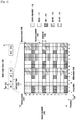
- FIG. 1 is a diagram illustrating a structure of the radio resource in downlink of the LTE and LTE-A system.
- FIG. 1 shows the basic structure of time-frequency grid of radio resource the mapping relationship between downlink physical channel and signals for transmitting data and control channels in the downlink of an LTE/LTE-A system.
- the horizontal axis denotes time
- the vertical axis denotes frequency.
- the smallest unit of transmission in time domain is OFDM symbol 104
- a subframe spans 1ms and consists of two 0.5 ms slots
- a radio frame 103 spans 10ms and consists of 20 slots, i.e. 10 subframes.
- the smallest unit of transmission in frequency domain is subcarrier 105, and the entire system bandwidth 109 consists of total NBW subcarriers.
- NBW is in proportion to the system bandwidth.
- Resource Element (RE) 106 is the basic unit indicated by OFDM symbol index and subcarrier index.
- the control channels include Physical Control Format Indicator Channel (PCFICH) carrying an indicator indicating the value N, Physical Downlink Control Channel (PDCCH) carrying uplink or downlink scheduling information, and Physical HARQ Indicator Channel (PHICH) carrying HARQ ACK/NACK.
- PCFICH Physical Control Format Indicator Channel
- PDCH Physical Downlink Control Channel
- PHICH Physical HARQ Indicator Channel
- the Physical Downlink Shared Channel (PDSCH) 111 is transmitted at the region where no downlink control channels are mapped.
- An evolved Node B transmits Reference Signal (RS) for use in downlink channel state measurement or PDSCH decoding at a User Equipment (UE).
- the RS is a pilot signal.
- the RS may is categorized into one of Cell-specific Reference Signal (CRS) 112 which all UEs can receive within the cell, Channel Status Information Reference Signal (CSI-RS) transmitted on different antenna ports using small amount of resource as compared to CRS, and Demodulation Reference Signal (DM-RS) 113 referenced to decode PDSCH scheduled to a predetermined UE.
- CRS Cell-specific Reference Signal
- CSI-RS Channel Status Information Reference Signal
- DM-RS Demodulation Reference Signal
- An antenna port is a logical concept, and the CSI-RS is defined per antenna port for use in measuring channel status of each antenna port. If the same CSI-RS is transmitted through multiple physical antennas, the UE cannot discriminate among the physical antennas but recognizes as single antenna port.
- the eNB may transmit CSI-RS at cell-specific positions.
- the reason for assigning the time and frequency resources at cell specific positions is to prevent inter-cell interference of CSI-RS.
- the eNB transmits Primary Synchronization Signal (PSS) and Secondary Synchronization Signal (SSS).
- PSS Primary Synchronization Signal
- SSS Secondary Synchronization Signal
- the eNB uses predetermined sequences for the respective PSS and SSS which are transmitted at predetermined positions in unit of radio frame repeatedly.
- FIG. 2 is a diagram illustrating the positions of PSS and SSS in a radio frame of LTE/LTE-A FDD system.
- the PSS is transmitted at OFDM symbol#6 201 and 203 of subframe#0 and subframe#5 in the time domain.
- the SSS is transmitted at OFDM symbol#5 202 and 204 of subframe#0 and subframe#5.
- the PSS and SSS are mapped to 6 RBs 205 of the system bandwidth.
- the UE uses PSS and SSS for tracking the time and frequency of the corresponding cell continuously and detects and measures PSS and SSS of neighboring cells as preparation for handover to neighboring cell.
- US 2011/0306340 A1 discloses a method for an extended cell search for a heterogenous network that shall enable better detection of pico cells with low transmission power.
- US 2010/0317343 A1 discloses methods for improved observed time difference of arrival (OTDOA) measurements that shall enable a positioning of a terminal.
- US 2012/257515 A1 discloses a method for reference signal port discovery involving multiple transmission points, performed by user equipment.
- US 2009/156225 A1 discloses a method for cell measurement employing indicators from respective cell to indicate the differences.
- US 2004/100935 A1 discloses a method of classifying a ray to a given cell, the ray being received at a code division multiple access receiver
- the present invention has been made in an effort to solve the above problem and aims to provide a method and apparatus for improving energy efficiency of the system in such a way that the terminal performs cell search with a discovery signal, acquires time/frequency synchronization of the corresponding cell, and for operating the cell in an active state or a dormant state.
- the discovery signal transmission/reception method of the present disclosure is capable of improving energy efficiency of a mobile communication system.
- the base station is an entity of allocating resources to the UE and often referred to eNode B, eNB, Node B, BS, radio access unit, base station controller, or network node.
- the terminal may be any of User Equipment (UE), Mobile Station (MS), cellular phone, smartphone, computer, and multimedia system equipped with a communication function.
- UE User Equipment
- MS Mobile Station
- cellular phone smartphone, computer, and multimedia system equipped with a communication function.
- the term 'uplink (UL)' denotes the radio link for transmitting data and/or control signal from the terminal to the base station
- the term 'downlink (DL)' denotes the radio link for transmitting data and/or control signal from the base station to the terminal.
- the present disclosure can be applied to other communication systems having the similar technical background and channel format. Also, it will be understood by those skilled in the art that the present disclosure can be applied to other communication systems with a slight modification.
- a transmission method according to an embodiment of the present disclosure may be applied to High Speed Packet Access (HSPA) system.
- HSPA High Speed Packet Access
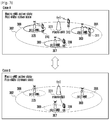
- FIG. 3 is a diagram illustrating exemplary cases of system operations according to an embodiment of the present disclosure.
- a plurality of pico eNBs 303, 305, and 307 having relatively small coverage areas 304, 306, and 308 are deployed within the coverage area 302 of the macro eNB 301.
- the macro and pico eNBs may operate on the same or different frequencies.
- the macro eNB transits signals at relatively high transmit power and has large coverage as compared to the pico eNB.
- the shorter the propagation path the less the attenuation of the signal transmitted by the UE or eNB is. Accordingly, when the signal propagation path is show, it is possible to provide high speed data service at relatively low transmission power level and with low interference probability.
- the close eNB (pico or macro eNB) serves the corresponding UE, resulting in improvement of entire system throughput.
- the UE 312 is served by the macro eNB 301, the UE 309 by the pico eNB 307, the UE 310 by the pico eNB 305, and the UE 311 by the pico eNB 303.
- the pico eNBs 303, 305, and 307 enter the dormant state while the macro eNB operates in the active state so as to improve the energy efficiency of the system.
- the macro eNB since the macro eNB has relatively large coverage area, it stays in the active state as far as possible to support UE mobility. That is, the UE 309 is served by the macro eNB 301.
- the eNB In the dormant state, the eNB suspends transmission/reception of common data channel, control channel, and RS and transmits the discovery signal for UE's cell sporadically. This is advantageous in reduction of energy consumption of the eNB.
- the eNB In the active state, the eNB maintains transmission/reception of the common data channel, control channel, and RS.
- Case A is directed to the situation where all eNBs are in the active state
- Case B is directed to the situation where all or some of the eNBs are in the dormant state.
- Case B if a plurality of UEs request for being served within the coverage area of the macro eNB, it is necessary to transition the situation to Case A.
- the UE has to discover the eNBs 303, 305, and 307 operating in the dormant state and notifies the macro eNB of this to transition the operation state of the pico eNBs 303, 305, and 307 to the active state.
- FIG. 4 is a signal flow diagram illustrating signal flows between the UE and eNBs according to an embodiment of the present invention.
- FIG. 4 shows a procedure in which the UE receives a discovery signal from the eNB and makes a handover to the corresponding eNB.
- the UE 401 is served by the serving eNB 1 402 and the eNB 2 403 transmits the discovery signal as a neighbor cell of the eNB 1 402 to support the UE's cell search.
- the eNB 1 402 identifies the discovery signal of the second eNB 2 403 at operation 410.
- the eNB 1 402 is capable of setting the discovery signal configuration of the eNB 2 403 and acquiring the set discovery signal configuration of the eNB 2 403.
- the eNB 1 402 may transmit the set discovery signal to the eNB 2 403.
- the eNB 1 402 also may receive the discovery signal configuration of the eNB 2 403 from the eNB 2 403 and identify the discovery signal.
- the discovery signal configuration may include discovery signal transmission interval, transmission timing, bandwidth, resource mapping information, sequence information, etc.
- the eNB 1 402 forwards the discovery signal configuration of the second eNB 2 403 to the UE 401 at operation 415.
- the eNB 1 402 may send the discovery signal configuration information of other eNBs as well as eNB 2 403.
- the UE 401 receives the discovery signal transmitted by the eNB 2 403 using the acquired discovery signal configuration at operation 420.
- the UE acquires subframe/radio frame synchronization and cell ID of the eNB 2 (or cell) 403 from the received discovery signal.
- the UE 401 also measures the signal strength of the received discovery signal.
- the description is directed to the case where the UE 401 receives the discovery signal of the eNB 2 403, it may receive the discover signal transmitted by another eNB using the discovery signal configuration of the corresponding eNB.
- the UE 401 sends the eNB 1 402 a measurement report including discovery signal detection and measurement result at operation 425.
- the measurement report may include cell ID(s) and received signal strength of the one or more discovery signals.
- the UE transmits only the measurement report on the discovery signals of which received signal strength is greater than a predetermined threshold value to the eNB 1 402.
- the threshold value may be included in the discovery signal configuration transmitted from the eNB 1 402 to the UE 401 or may be a fixed value.
- the eNB 1 402 determines whether to make a handover decision on the UE 401 to the eNB 2 403 based on the measurement report from the UE 401 at operation 430. If the measurement report includes the cell ID of the eNB 2 403 at operation 430 and if the received signal strength is strong enough, the eNB 1 402 sends the eNB 2 403 a handover preparation request message for handover of the UE 401 to the eNB 2 403 at operation 435.
- the eNB 1 402 receives a handover preparation complete message from the eNB 2 403 in response to the handover preparation request at operation 440 and sends the UE 401 a handover command at operation 445.
- the UE 401 Upon receipt of the handover command from the eNB 1 402, the UE 401 performs handover to the eNB 2 403 according to the handover command at operation 450.
- the eNB 1 402 is a macro eNB and the eNB 2 403 is a pico eNB.
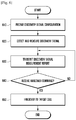
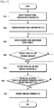
- FIG. 5 is a flowchart illustrating the eNB procedure according to an embodiment of the present invention. Particularly, FIG. 5 is a flowchart illustrating the operation procedure of the eNB 1 402 of FIG. 4 or a macro eNB.
- the eNB acquires the discovery signal configuration of the neighbor cell at operation 510 and notifies the UE of the discovery signal configuration of the neighbor cell at operation 520.
- the discovery signal configuration may include the discovery signal transmission interval, transmission timing, bandwidth, resource mapping information, sequence information, etc., and the eNB may acquire the discovery signal configurations of one or more neighbor cells and notify the UE of the acquired discover signal configurations.
- the eNB receives the measurement report including information on the cell ID and received signal strength corresponding to one or more discovery signals from the UE at operation 530.
- the measurement report may include information on only the discovery signals of which received signal strength is greater than the threshold value to reduce unnecessary transmission overhead of the UE, and the threshold value may be included in the discovery signal configuration information at operation 520 or may be a fixed value.
- the eNB determines whether to make a handover decision for the UE based on the received measurement report at operation 540. If the measurement report includes the cell ID of the neighbor eNB and if the received signal strength is strong enough, the eNB makes a handover decision for the UE.
- the eNB If it is determined to make no handover decision for the UE at operation 540, the eNB returns the procedure to operation 530 to receive next measurement report from the UE. If it is determined to make a handover decision for the UE at operation 540, the eNB sends a handover target cell a handover preparation request message at operation 550. If a handover preparation complete message is received from the target cell, the eNB commands the UE to make a handover to the target cell at operation 570. If no handover preparation complete message is received, the eNB returns the procedure to operation 550.
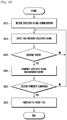
- FIG. 6 is a flowchart illustrating the UE procedure according to an embodiment of the present disclosure.
- the UE acquires the discovery signal configuration of a neighbor cell from the eNB at operation 610.
- the discovery signal configuration may include the discovery signal transmission interval, transmission timing, bandwidth, resource mapping information, sequence information, etc. and the UE may receive the discovery signal configuration of one or more cells from the eNB.
- the UE detects and measures the discovery cell using the discovery signal configuration of the acquired neighbor cell at operation 620.
- the UE sends the eNB a measurement report about the measure discovery signal at operation 630.
- the UE includes only the measurement result on the discovery signals of which strength is greater than a predetermined threshold value in the measurement report to be transmitted to the eNB.
- the threshold value may be included in the discovery signal configuration transmitted from the eNB to the UE at operation 610 or may be a fixed value.
- the UE determines whether a handover command is received from the eNB at operation 640. If no handover command is received at operation 640, the UE returns the procedure to operation 630. If a handover command is received at operation 640, the UE performs handover to the target cell indicated by the handover command at operation 650.
- the discovery signal configuration includes the discovery signal transmission interval, transmission timing, bandwidth, resource mapping information, sequence information, etc.
- the discovery signal may be transmitted at a relatively long interval instead of PSS/SSS transmitted at an interval of a radio frame (10ms). Accordingly, if no data traffic occurs for the duration without discovery signal transmission, the eNB enters the dormant state to stop transmission/reception operation, resulting in increase of system energy efficiency. Likewise, the UE performs downlink signal reception only for the duration in which the discovery signal is transmitted so as to reduce power consumption.
- the transmission interval of the discovery signal is longer than the transmission interval of PSS/SSS in the time domain, it is possible for the UE to perform cell search and acquire subframe/radio frame synchronization with extra delay with the discovery signal by mapping the signal to relatively more resource in the frequency domain. That is, it is possible to improve the discovery signal reception performance and minimize the time for the UE to perform cell search and acquire subframe/radio frame synchronization.
- the UE If there is no pre-information notice about the discovery signal transmitted at a long interval, the UE has to keep monitoring the downlink signal to detect the discovery signal and thus fails achieving the goal reducing the power consumption of the UE by introducing the discovery signal.
- the eNB notifies the UE of the discovery signal configuration of the neighbor cell such that the UE recognize the timing when it starts monitoring the discovery signal based on the discovery signal configuration.
- the timing information may be configured as described in embodiment 1-1 or 1-2.
- Embodiment 1-1 is directed to a method for configuring the timing information with the transmission interval and timing offset of the discovery signal.
- the discovery signal transmission interval is identical with the radio frame period (10ms).
- the timing offset is the relative timing for transmitting the discovery signal in the serving cell of the UE. For example, the UE attempts detecting the discovery signal at the time fulfilling Math Figure 1 .
- SFN mod transmission period timing offset
- the System Frame Number is the SFN of the cell to which the UE connects currently and a kind of counter counting the radio frame in the range from 0 to 1023 and repeats at an interval of 1024 radio frames.
- the eNB may transmit the discovery signal transmission timing informations on the respective cells to the UE.
- Embodiment 1-2 is directed to a method of notifying whether the neighbor cell has acquired with the timing synchronization with the serving cell of the UE. If the neighbor cell and the serving cell have acquired timing synchronization, the UE recognizes that the discovery signal transmission timing of the neighbor cell is identical with that of the serving cell and starts monitoring the discovery signal at the corresponding timing. Whether the timing synchronization is acquired between the neighbor and serving cells may be notified using in-bit signal. If this bit may be set to 0 for indicating the timing match between the neighbor and serving cells or 1 for indicating the timing mismatch between the neighbor and serving cells.
- extra signaling may be defined.
- the eNB notifies the UE capable of receiving both the PSS/SSS and discovery signal of the signals which the UE has to monitor for cell search or subframe/radio frame synchronization in detail. In this way, it is possible to reduce the UE's processing overhead caused by monitoring both the PSS/SSS and discovery signal.
- the eNB also may instruct the UE to monitor the discovery signal for cell search and PSS/SSS for subframe/radio frame synchronization through this signaling.
- the discovery signal may be defined as a function of cell ID.
- the current LTE/LTE-A system supports total 504 cell IDs, and it is possible to reduce the UE's discovery signal reception processing overhead with the signal of restricting the number of cell IDs which the UE has to monitor.
- the UE is capable of acquiring the information on the timings for monitoring the discovery signal from the eNB.
- This embodiment is directed to a method of acquiring the detailed timing information (e.g. SFN) of the cell transmitting the discovery signal from the discovery signal received by the UE. Since the RACH transmission timing, SRS transmission timing, and CSI-RS reception timing of the UE in a certain cell is determined by SFN, the UE has to acquire accurate SFN information.
- SFN detailed timing information
- the discovery signal configuration information may be transmitted from the eNB to the UE.
- the eNB may send the UE the information on the discovery signal configuration information included in or along with the discovery signal configuration.
- the discovery signal configuration information also may be stored in the UE in advance. At this time, the disclosry signal configuration information may be configured by the wireless communication service provider.
- FIG. 7 is a diagram illustrating a configuration of the discovery signal according to an example of the present disclosure.
- Example 2-1 is described with reference to FIG. 7 .
- the eNB which transmits the discovery signal may be configured to transmit total N discovery signal sequences of sequence#0, sequence#1, ..., sequence#(N-1) at the transmission timings defined through the method of ⁇ First embodiment> at the discovery signal transmission interval P at every 1024 radio frames corresponding to SFN period.
- the ceiling (x) denotes the minimum integer which is not less than x.
- mapping the transmission timing 701 of the sequence#0 of cell B to the SFN#0 of cell B has been pre-negotiated or notified by the eNB to the UE. Accordingly, if the sequence#0 as the discovery signal is detected, the UE becomes aware of the SFN#0 of cell B which corresponds to the discovery signal transmission timing 701 of cell B.
- FIG. 8 is a diagram illustrating a configuration of the discovery signal according to another example of the present disclosure.
- the first M discovery signals are transmitted at the transmission timings 801 to 804 repeatedly using sequence#0 817, the second M discovery signals at the transmission timings 805 to 808 repeatedly using sequence#1 818, the third M discovery signals at the transmission timings 809 to 812 repeatedly using sequence#2 819, and the fourth M discovery signals at transmission timings 813 to 816 repeatedly using sequence#3 820.
- mapping the transmission timing 801 of sequence#0 to the SFN#0 of the cell transmitting the discovery signal has been pre-negotiated or notified by the eNB to the UE. Accordingly, the detection of sequence#0 makes it possible for the UE to know the SFN of cell B which has transmitted the discovery signal is in the range of 0 to 255, the detection of sequence#1 makes it possible for the UE to know the SFN of cell B which has transmitted the discovery signal is in the range of 256 to 511, the detection of sequence#2 makes it possible for the UE to know the SFN of cell B which has transmitted the discovery signal is in the range of 512 to 767, and the detection of sequence#3 makes it possible for the UE to know the SFN of cell B which has transmitted the discovery signal is in the range of 768 to 1023.
- the UE may determine SFN of the cell which has transmitted the discovery signal based on a predetermined SFN range.
- the UE may determine SFN of the cell which has transmitted the discovery signal through blind detection.
- the number of the blind detection of the UE can be reduced to maximum number of 256 compared with the maximum number of 1024 that is the number of the blind detection when the UE does not know the range of the SFN.
- Example 2-2 is useful for the case where the discovery signal transmission interval P is relatively short and the number of sequences as discovery signal is limited.
- Example 2-3 is an alternative of [Example 2-2] and is capable of transmitting the discovery signals sorted into groups of M discovery signals using a unique sequence as distributed within the SFN period.
- FIG. 9 is a diagram illustrating a configuration of the discovery signal according to still another example of the present disclosure.
- sequence#0 917, sequence#1 918, sequence#2 919, and sequence#3 920 are mapped to the discovery signal transmission timings 901 to 916 respectively.
- mapping the transmission timing 901 of the sequence#0 to SFN#0 has been pre-negotiated or notified by the eNB to the UE. Accordingly, if the sequence#0 is detected, the UE becomes aware of the SFN of the cell which has transmitted the discovery signal is one of SFN#0, SFN#256, SFN#512, and SFN#768 corresponding to the transmission timings 901, 905, 909, and 913 of sequence#0. At this time, the UE may determine SFN of the cell which has transmitted the discovery signal based on a predetermined SFN range. The UE may determine SFN of the cell which has transmitted the discovery signal through blind detection.
- the third example is directed to a procedure of transmitting the discovery signal including the state information indicating whether the corresponding cell is in the active state or dormant state.
- the discovery signal sequences are sorted into two groups: one for use in the cell transmitting the discovery signal is in the active state and the other for use in the cell transmitting the discovery signal is in the dormant state.
- the information on the groups for use in the active and dormant state cells is shared between the eNB and the UE. This information may be included in the discovery signal configuration of the neighbor cell which is notified by the eNB to the UE in advance.
- the sequence for use in transmitting the discovery signal is generated using the cell ID and state information of the cell transmitting the discovery signal.
- the discovery signal sequence may be expressed as Math Figure 2 by applying this example to the sequence for use in legacy PSS.
- Math Figure 2 expresses 62-sample length sequence as multiplication of frequency domain Zadoff-Chu sequence as root sequence index u and the cell state information a.
- the root sequence index u is determined according to the cell ID.
- the length of sequence is expressed by Math Figure 2 herein, the discovery signal sequence may have different length.
- the eNB transmits the discovery signal only when the corresponding cell is in the dormant state but not when the corresponding cell is in the active state.
- a is set to 0 for the cell in the active state or 1 for the cell in the dormant state.
- the eNB is capable of conserving the transmit power by suspending transmission of the discovery signal for the cell in the active state.
- the eNB transmits the discovery signal regardless of the cell state.
- the UE is capable of checking the state of the cell based on the discovery signal generated according to [example 3-1], [example 3-2], or [example 3-3]. A description is made of the UE operation after checking the state of the corresponding cell hereinafter.
- the UE sends the eNB the measurement report including the discovery signal detection and measurement result. However, if the cell state information of the discovery signal indicates the active state, the UE does not send the eNB the discovery signal detection and measurement result. In this way, it is possible to reduce the measurement report overhead of the UE while guaranteeing that the cells included in the measurement report are all in the dormant state.
- the measurement report includes the cell ID and received signal strength of one or more discovery signals. In order to reduce the unnecessary signaling overhead of the UE, it is possible to include only the measurement result on the discovery signals of which received signal strength is greater than a predetermined threshold value in the measurement report to be transmitted to the eNB.
- the eNB determines whether to activate the cells indicated in the measurement report or maintain the dormant state of these cells. If it is determined to activate a cell, the eNB determine whether to make a handover decision for the UE to any activated cell.
- the fifth example is directed to a method of transmitting the discovery signal detection and measurement result from the UE to the eNB in the case when the cell state information included in the discovery signal indicates the activate state.
- the UE does not send the eNB the discovery signal detection and measurement result. In this way, it is possible to reduce the measurement report overhead of the UE while guaranteeing that the cells included in the measurement report are all in the active state.
- the measurement report includes the cell ID and received signal strength of one or more discovery signals.
- the eNB determines whether to make a handover decision for the UE to any active cell.
- the UE configures the measurement report regardless of the cell state unlike the fourth and fifth example in which the measurement report is configured with the measurement results for the cells in one of the dormant and active states.
- the measurement report includes the cell ID, received signal strength, and cell state that are acquired based on the discovery signals.
- the method of the sixth example is useful in the case where the eNB has no information on the cell states of neighbor cells. That is, it is determined that the cell A is in the dormant state and the received signal strength of the signal from the cell A is strong enough based on the measurement report from the UE, the eNB assumes that the cell A is in the active state.
- FIG. 10 is a flowchart illustrating the UE procedure according to another example of the present disclosure. Particularly, FIG. 10 is directed to the UE operations in the fourth example.
- the UE acquires the discovery signal configuration of the neighbor cell from the eNB at operation 1010.
- the discovery signal configuration may include the discovery signal transmission interval, transmission timing, bandwidth, resource mapping information, and sequence information; and the UE may receive the discovery signal configuration of one or more cells from the eNB.
- the UE detects and measures the discovery signals based on the acquired discovery signal configurations of the neighbor cells. Afterward, the UE determines whether the cell corresponding to the discovery signal detected at operation 1020 is in the dormant state at operation 1030. If it is determined that the cell is not in the dormant state at operation 1030, the UE returns the procedure to operation 1020. If it is determined that the cell is in the dormant state at operation 1030, the UE sends, at operation 1040, the eNB the measurement report about the discovery signal measured at operation 1020.
- the UE determines whether a handover command is received from the eNB at operation 1050. If no handover command is received, the UE returns the procedure to operation 1020 and, otherwise if the handover command is received, performs handover to the target cell indicated in the handover command at operation 1060.
- the fourth and fifth example may be described with reference to FIG. 10 along with the following modification.
- the UE determines whether the cell corresponding to the discovery signal detected at operation 1030 is in the active state such that if the cell is in the active state, the procedure goes to operation 1040 and, otherwise, returns to operation 1020.
- the determination operation 1030 is omitted such that the cell state of the corresponding cell is included in the discovery signal measurement report of the UE at operation 1040.
- FIG. 11 is a flowchart illustrating the eNB procedure according to another example of the present disclosure. Particularly, FIG. 11 is directed to the UE operations in the fourth example.
- the eNB acquires the discovery signal configuration of the neighbor cell from the neighbor cell at operation 1110 and forwards the discovery signal configuration of the neighbor cell to the UE at operation 1120.
- the discovery signal configuration may include the discovery signal transmission interval, transmission timing, bandwidth, resource mapping information, and sequence information; and the eNB may acquire the discovery signal configurations of one or more neighbor cells and forwards the acquired discovery signal configurations to the UE.
- the eNB receives the measurement report including cell IDs and received signal strengths on one or more discovery signals from the UE at operation 1130.
- the eNB may receive the measurement report on the discovery signals of which received signal strength is greater than a predetermined threshold value which may be included in the discovery signal configuration or may be a fixed value.
- the eNB determines whether to activate the cells included in the measurement report and, if so, whether to make a handover decision for the UE to any activated cell at operation 1140. If it is determined to do not activate the cells at operation 1140, the eNB returns the procedure to operation 1130 to receive next measurement report from the UE. Otherwise if it is determined to activate the cell and make a handover decision for the UE to any activated cell at operation 1140, the eNB requests the cell to transition to the activate state and prepare for handover of the UE at operation 1150.
- the eNB commands the UE to make a handover to the corresponding cell at operation 1170 and, otherwise if the cell activation complete and handover preparation complete message is not received, returns the procedure to operation 1150.
- the eNB procedure in the fifth example may follow the eNB procedure of FIG. 5
- the eNB procedure in the sixth example may follow modification of the eNB procedure of FIGs. 5 and 11 .
- the seventh example is directed to a method of mapping the discovery signal onto the time-frequency resource grid.
- FIG. 12 is a diagram illustrating the discovery signal mapped onto the time-frequency resource grid according to an example of the present disclosure.
- the subframe mapping positions of the signals or control channels essential for the operation of the LTE/LTE-A system such as PSS/SSS, Physical Broadcasting Channel (PBCH), and paging are fixed. Accordingly, the discovery signal is mapped so as to be transmitted at subframes #1, #2, #3, #6, #7, and #8 in FDD mode and subframes #3, #4, #7, #8, and #9 in TDD mode to avoid collision with the signals or control channels as far as possible.
- the discovery signal is mapped to the positions without collision with CRS, DM-RS, and CSI-RS in the subframe and where consecutive resource allocation is possible in the time or frequency domain.
- the discovery signal it is preferred to map the discovery signal to the time-frequency regions denoted by reference numbers 1212, 1213, 1214, and 1215 in FIG. 12 to fulfil the above conditions in consideration of the mapping relationship between the basic time-frequency resource structure of FIG. 1 and the downlink physical channel and signals.
- the frequency region may be expanded without collision with other signals if necessary.
- the region 1213 of OFDM symbol#3 of slot#0 to which only the PDSCH is mapped is available to map the discovery signal thereto without collision with other signals.
- the eNB can adjust the resource mapping for PDSCH in its scheduling decision, it is possible to avoid the collision of the discovery signal at the position 1213 of the OFDM symbol#3 of slot#0.
- the eNB may use these positions for transmitting the discovery signal by canceling the CSI-RS mapping thereto.
- FIG. 13 is a block diagram illustrating a configuration of the eNB according to an embodiment of the present disclosure. Detailed descriptions on the components that are not related to the present disclosure directly are omitted herein for explanation convenience.
- the eNB 1300 comprises a transmitter 1335 including a discovery signal generator 1305, a PSS/SSS generator 1310, a PDCCH generator 1315, a PDSCH generator 1320, a multiplexer 1325, and an RF transmitter 1330; a receiver 1360 including a PUCCH receiver 1340, a PUSCH receiver 1345, a demultiplexer 1350, and a RF receiver 1355; and a scheduler 1365.
- the transmitter 1335 and the receiver 1360 may be referred to as a transceiver, and the scheduler may be referred to as controller or processor.
- the scheduler 1365 controls the function blocks of the transmitter 1335 and the receiver 1360 to generate and acquire predetermined signals and determines whether to control a cell to operate in the active or dormant state. If it is determined to operate the cell in the dormant state, the cell minimizes the signal transmission/reception operation.
- the discovery signal generator 1305 generates the discovery signal which is mapped to the time-frequency region determined under the control of the scheduler 1365.
- the PSS/SSS generator 1310 generates PSS/SSS under the control of the scheduler 1365.
- the PDCCH generator 1315 generates Physical Downlink Control Channel (PDCCH) through channel coding and modulation process on the downlink control information including scheduling information under the control of the scheduler 1365.
- PDCH Physical Downlink Control Channel
- the PDSCH generator 1320 generates Physical Downlink Control Shared Channel (PDSCH) through channel coding and modulation process on the downlink data under the control of the scheduler 1365.
- the discovery signal generated by the discovery signal generator 1305, the PSS/SSS generated by the PSS/SSS generator 1310, the PDCCH generated by the PDCCH generator 1315, and the PDSCH generated by the PDSCH generator 1320 are multiplexed by the multiplexer 1325, mapped to the corresponding time-frequency region, and processed by the RF transmitter 1330 to be transmitted to the UE.
- the receiver 1360 of the eNB demultiplexes the signal received from the UE by means of the demultiplexer 1350 and delivers the demultiplexed signal to the PUCCH receiver 1340 and PUSCH receiver 1345.
- the PUCCH receiver 1340 performs demodulation and channel decoding process on the Physical Uplink Control Channel (PUCCH) including UCI to acquire HARQ ACK/NACK, CSI, etc.
- the PUSCH receiver 2345 performs demodulation and channel decoding process on the Physical Uplink Control Shared Channel (PUSCH) including uplink data to acquire the uplink data transmitted by the UE.
- the receiver 1360 of the eNB transfers the output results of the PUCCH receiver 1340 and the PUSCH receiver 1345 to the scheduler 1365 for use in scheduling process.
- FIG. 14 is a block diagram illustrating a configuration of the UE according to an embodiment of the present disclosure. Detailed descriptions on the components that are not related to the present disclosure directly are omitted herein for explanation convenience.
- the UE comprises a transmitter 1425 including a PUCCH generator 1405, a PUSCH generator 1410, a multiplexer 1415, and an RF transmitter 1420; a receiver 1460 including a discovery signal receiver 1430, a PSS/SSS receiver 1435, a PDCCH receiver 1440, a PDSCH receiver 1445, a demultiplexer 1450, and an RF receiver 1455; and a controller 1465.
- the controller 1465 controls the UE to extract the discovery signal from the control information transmitted by the eNB and controls the functions blocks of the receiver 1460 and the transmitter 1425.
- the transmitter 1425 and the receiver 1460 may be referred to as transceiver.
- the discovery signal receiver 1430 of the receiver 1460 performs discovery signal acquisition process at the predetermined time-frequency region.
- the PSS/SSS receiver 1435 performs PSS/SSS acquisition process at the predetermined time-frequency region.
- the PDCCH receiver 1440 performs demodulation and channel decoding process on the received PDCCH to acquire downlink control information.
- the PDSCH receiver 1445 performs demodulation and channel decoding process on the PDSCH to acquire downlink data.
- the PUCCH generator 1405 of the transmitter 1425 performs channel coding and modulation process on the UCI including HARQ ACK/NACK and CSI to generate PUCCH.
- the PUSCH generator 1410 performs channel coding and modulation process on the uplink data to generate PUSCH.
- the PUCCH generated by the PUCCH generator 1405 and the PUSCH generated by the PUSCH generator 1410 are multiplexed by the multiplexer 1415 and processed by the RF transmitter 1420 to be transmitted to the eNB.
- the discovery signal transmission/reception method of the present disclosure is capable of improving energy efficiency of a mobile communication system.
- These computer program instructions may also be stored in a computer-readable memory that can direct a computer or other programmable data processing apparatus to function in a particular manner, such that the instructions stored in the computer-readable memory produce an article of manufacture including instruction means which implement the function/act specified in the flowchart and/or block diagram block or blocks.
- the computer program instructions may also be loaded onto a computer or other programmable data processing apparatus to cause a series of operational steps to be performed on the computer or other programmable apparatus to produce a computer implemented process such that the instructions which execute on the computer or other programmable apparatus provide steps for implementing the functions/acts specified in the flowchart and/or block diagram block or blocks.
- the respective block diagrams may illustrate parts of modules, segments or codes including at least one or more executable instructions for performing specific logic function(s).
- the functions of the blocks may be performed in different order in several modifications. For example, two successive blocks may be performed substantially at the same time, or may be performed in reverse order according to their functions.
- module means, but is not limited to, a software or hardware component, such as a Field Programmable Gate Array (FPGA) or Application Specific Integrated Circuit (ASIC), which performs certain tasks.
- a module may advantageously be configured to reside on the addressable storage medium and configured to be executed on one or more processors.
- a module may include, by way of example, components, such as software components, object-oriented software components, class components and task components, processes, functions, attributes, procedures, subroutines, segments of program code, drivers, firmware, microcode, circuitry, data, databases, data structures, tables, arrays, and variables.
- the functionality provided for in the components and modules may be combined into fewer components and modules or further separated into additional components and modules.
- the components and modules may be implemented such that they execute one or more CPUs in a device or a secure multimedia card.
Landscapes
- Engineering & Computer Science (AREA)
- Computer Networks & Wireless Communication (AREA)
- Signal Processing (AREA)
- Computer Security & Cryptography (AREA)
- Mobile Radio Communication Systems (AREA)
Claims (9)
- Procédé de réception de rapport de mesure réalisé par une station de base (402) dans un système de communication mobile, le procédé de réception de rapport de mesure comprenant :l'identification d'une configuration de signal de découverte d'une cellule voisine (403), la configuration de signal de découverte incluant des informations sur une période et un décalage pour la mesure d'un signal de découverte de la cellule voisine (403) ;la transmission (415) de la configuration de signal de découverte à un terminal (401) ; etla réception (425), par le terminal, du rapport de mesure incluant un résultat de mesure sur le signal de découverte selon la configuration de signal de découverte,dans lequel la période est définie comme un multiple d'une trame radio du système de communication mobile et le décalage est un temps relatif pour la mesure du signal de découverte dans une cellule de desserte du terminal (401), etdans lequel la période et le décalage indiquent une trame radio de numéro de trame système, system frame number - SFN, n de la cellule de desserte dans laquelle le terminal mesure le signal de découverte sur la base d'une formule SFN n mod la période = le décalage afin de prendre en charge la recherche de cellule pour la cellule voisine.
- Procédé de réception de rapport de mesure selon la revendication 1, comprenant en outre :
la détermination (430) de s'il faut effectuer un transfert vers la cellule voisine du terminal sur la base du résultat de mesure du signal de découverte qui est transmis sur la cellule voisine. - Station de base (1300) pour la réception d'un rapport de mesure dans un système de communication mobile, la station de base comprenant :un émetteur-récepteur (1335, 1360) configuré pour transmettre et recevoir des signaux vers et depuis un terminal ; etun contrôleur (1365) configuré pour :identifier une configuration de signal de découverte d'une cellule voisine, la configuration de signal de découverte incluant des informations sur une période et un décalage pour la mesure d'un signal de découverte de la cellule voisine,contrôler l'émetteur-récepteur pour transmettre, au terminal, la configuration de signal de découverte, etcontrôler le récepteur pour recevoir, par le terminal, le rapport de mesure incluant un résultat de mesure sur le signal de découverte selon la configuration de signal de découverte,dans laquelle la période est définie comme un multiple d'une trame radio du système de communication mobile et le décalage est un temps relatif pour la mesure du signal de découverte dans une cellule de desserte du terminal, etdans laquelle la période et le décalage indiquent une trame radio de numéro de trame système, system frame number - SFN, n de la cellule de desserte dans laquelle le terminal mesure le signal de découverte sur la base d'une formule SFN n mod la période = le décalage afin de prendre en charge la recherche de cellule pour la cellule voisine.
- Station de base selon la revendication 3, dans laquelle le contrôleur est en outre configuré pour déterminer s'il faut effectuer un transfert vers la cellule voisine du terminal sur la base du résultat de mesure sur un signal de découverte de la cellule voisine.
- Procédé de réception de signal de découverte réalisé par un terminal (401) dans un système de communication mobile, le procédé de réception de signal de découverte comprenant :la réception (415) d'une configuration de signal de découverte d'une cellule voisine à partir d'une station de base, la configuration de signal de découverte incluant des informations sur une période et un décalage pour la mesure d'un signal de découverte de la cellule voisine ;la mesure (420) du signal de découverte selon la configuration de signal de découverte ; etla transmission (425) d'un rapport de mesure incluant un résultat de mesure du signal de découverte de la cellule voisine à la station de base,dans lequel la période est définie comme un multiple d'une trame radio du système de communication mobile et le décalage est un temps relatif pour la mesure du signal de découverte dans une cellule de desserte du terminal, etdans lequel la période et le décalage indiquent une trame radio de numéro de trame système, system frame number - SFN, n de la cellule de desserte dans laquelle le terminal mesure le signal de découverte sur la base d'une formule SFN n mod la période = le décalage afin de prendre en charge la recherche de cellule pour la cellule voisine.
- Procédé de réception de signal de découverte selon la revendication 5, dans lequel le résultat de mesure sur le signal de découverte est envoyé à la station de base pour déterminer s'il faut effectuer un transfert vers la cellule voisine du terminal.
- Terminal (1400) pour la réception d'un signal de découverte dans un système de communication mobile, le terminal comprenant :un émetteur-récepteur (1425, 1460) configuré pour transmettre et recevoir des signaux vers et depuis une station de base ; etun contrôleur (1465) configuré pour :contrôler le récepteur pour recevoir une configuration de signal de découverte d'une cellule voisine à partir d'une station de base, la configuration de signal de découverte incluant des informations sur une période et un décalage pour la mesure d'un signal de découverte de la cellule voisine,mesurer le signal de découverte selon la configuration de signal de découverte, etcontrôler l'émetteur-récepteur pour transmettre un rapport de mesure incluant un résultat de mesure sur le signal de découverte de la cellule voisine à la station de base,dans lequel la période est définie comme un multiple d'une trame radio du système de communication mobile et le décalage est un temps relatif pour la mesure du signal de découverte dans une cellule de desserte du terminal, etdans lequel la période et le décalage indiquent une trame radio de numéro de trame système, system frame number - SFN, n de la cellule de desserte dans laquelle le terminal mesure le signal de découverte sur la base d'une formule SFN n mod la période = le décalage afin de prendre en charge la recherche de cellule pour la cellule voisine.
- Terminal selon la revendication 7, dans lequel le résultat de mesure sur le signal de découverte est envoyé à la station de base pour déterminer s'il faut effectuer un transfert vers la cellule voisine du terminal.
- Procédé de réception de rapport de mesure selon la revendication 1, station de base selon la revendication 3, procédé de réception de signal de découverte selon la revendication 5 ou terminal selon la revendication 7, dans lequel la configuration de signal de découverte comprend en outre des informations de mappage de ressources du signal de découverte et des informations de séquence sur le signal de découverte.
Priority Applications (1)
| Application Number | Priority Date | Filing Date | Title |
|---|---|---|---|
| PL13862052T PL2932758T3 (pl) | 2012-12-14 | 2013-12-12 | Sposób i urządzenie do przesyłania/odbioru sygnału wyszukiwania do użytku w systemie łączności komórkowej |
Applications Claiming Priority (2)
| Application Number | Priority Date | Filing Date | Title |
|---|---|---|---|
| KR1020120146378A KR101988506B1 (ko) | 2012-12-14 | 2012-12-14 | 무선 이동통신 시스템에서 디스커버리 신호를 송/수신하는 방법 및 장치 |
| PCT/KR2013/011517 WO2014092475A1 (fr) | 2012-12-14 | 2013-12-12 | Procédé et appareil d'émission/réception de signal de découverte pour une utilisation dans un système de communication mobile |
Publications (3)
| Publication Number | Publication Date |
|---|---|
| EP2932758A1 EP2932758A1 (fr) | 2015-10-21 |
| EP2932758A4 EP2932758A4 (fr) | 2016-08-10 |
| EP2932758B1 true EP2932758B1 (fr) | 2021-08-25 |
Family
ID=50931494
Family Applications (1)
| Application Number | Title | Priority Date | Filing Date |
|---|---|---|---|
| EP13862052.1A Active EP2932758B1 (fr) | 2012-12-14 | 2013-12-12 | Procédé et appareil d'émission/réception de signal de découverte pour une utilisation dans un système de communication mobile |
Country Status (7)
| Country | Link |
|---|---|
| US (6) | US9526064B2 (fr) |
| EP (1) | EP2932758B1 (fr) |
| KR (1) | KR101988506B1 (fr) |
| CN (2) | CN104956728B (fr) |
| ES (1) | ES2890100T3 (fr) |
| PL (1) | PL2932758T3 (fr) |
| WO (1) | WO2014092475A1 (fr) |
Families Citing this family (51)
| Publication number | Priority date | Publication date | Assignee | Title |
|---|---|---|---|---|
| KR101988506B1 (ko) | 2012-12-14 | 2019-09-30 | 삼성전자 주식회사 | 무선 이동통신 시스템에서 디스커버리 신호를 송/수신하는 방법 및 장치 |
| KR101698702B1 (ko) * | 2013-01-14 | 2017-01-20 | 엘지전자 주식회사 | 탐색 신호를 검출하는 방법 및 장치 |
| PL3435723T3 (pl) * | 2013-04-05 | 2020-06-15 | Telefonaktiebolaget Lm Ericsson (Publ) | UE, węzeł sieci i sposoby wspomagania pomiarów w konfiguracji sygnałów mieszanych |
| CN104285483B (zh) * | 2013-04-07 | 2018-07-13 | 华为技术有限公司 | 传输公共信号的方法及其装置 |
| US20150023191A1 (en) * | 2013-07-18 | 2015-01-22 | Electronics And Telecommunications Research Institute | Cell and mobile terminal discoverly method |
| US20150029877A1 (en) * | 2013-07-26 | 2015-01-29 | Qualcomm Incorporated | Discovery signals for lte |
| JP6053632B2 (ja) * | 2013-08-01 | 2016-12-27 | 株式会社Nttドコモ | ユーザ端末、無線基地局及び通信制御方法 |
| CN104349442B (zh) * | 2013-08-07 | 2019-07-12 | 中兴通讯股份有限公司 | 下行功率调整的通知方法及装置、获取方法及装置 |
| US10028160B2 (en) * | 2013-12-12 | 2018-07-17 | Telefonaktiebolaget Lm Ericsson (Publ) | Network node, wireless device and methods for handling evaluation of a secondary cell for a wireless device |
| CN105659694B (zh) | 2013-12-25 | 2020-09-04 | 松下电器(美国)知识产权公司 | 移动台及接收质量测量方法 |
| JP6297163B2 (ja) * | 2014-01-15 | 2018-03-20 | エルジー エレクトロニクス インコーポレイティド | 無線通信システムにおける探索信号に基づくセル探索過程の実行方法及び探索過程を実行するユーザ装置 |
| US20150215855A1 (en) * | 2014-01-23 | 2015-07-30 | Humax Holdings Co., Ltd. | Apparatus for cell specific reference signal transmission on lte small cell |
| EP3097711B1 (fr) | 2014-01-31 | 2018-12-05 | Huawei Technologies Co., Ltd. | Dispositif, réseau, et procédé d'adaptation réseau et d'utilisation d'un signal de référence de recherche en liaison descendante |
| WO2015117034A2 (fr) | 2014-01-31 | 2015-08-06 | Huawei Technologies Co., Ltd. | Dispositif, réseau, et procédé de découverte de cellule |
| WO2015124208A1 (fr) * | 2014-02-21 | 2015-08-27 | Huawei Technologies Co., Ltd. | Transmission d'informations de temporisation concernant l'état actif de stations de base utilisant la dtx |
| US9888430B2 (en) * | 2014-03-14 | 2018-02-06 | Intel IP Corporation | Enhanced node B, UE and method for selecting cell discovery signals in LTE networks |
| US10200159B2 (en) | 2014-04-29 | 2019-02-05 | Nec Corporation | Method and system for configuring device-to-device communication |
| CN105208543A (zh) * | 2014-06-09 | 2015-12-30 | 中国移动通信集团公司 | 一种小小区发现方法及系统、基站、用户设备 |
| EP3197224B1 (fr) * | 2014-07-29 | 2019-02-27 | LG Electronics Inc. | Procédé d'émission-réception de signal pour une communication de dispositif à dispositif (d2d) et appareil utilisé à cet effet dans un système de communication sans fil |
| EP3180945A1 (fr) * | 2014-08-15 | 2017-06-21 | Telefonaktiebolaget LM Ericsson (publ) | Configuration de signaux de découverte |
| CN105376869B (zh) * | 2014-08-22 | 2020-04-03 | 中兴通讯股份有限公司 | 一种在非授权载波上发送发现信号的方法、系统及接入点 |
| EP3836630B1 (fr) * | 2014-09-12 | 2022-10-26 | NEC Corporation | Station radio, terminal radio et procédé de mesure de terminal |
| KR102531481B1 (ko) * | 2014-09-24 | 2023-05-11 | 엘지전자 주식회사 | D2d 신호의 송신 방법 및 이를 위한 단말 |
| US20160183113A1 (en) * | 2014-12-23 | 2016-06-23 | Qualcomm Incorporated | Efficient pairwise ranging to nodes in a large cluster |
| US10512033B2 (en) * | 2015-01-29 | 2019-12-17 | Qualcomm Incorporated | Timing information for discovery in unlicensed spectrum |
| ES2847624T5 (es) | 2015-01-30 | 2024-02-23 | Nokia Solutions & Networks Oy | Método y aparato para realizar mediciones de gestión de recursos de radio |
| US10396965B2 (en) | 2015-03-06 | 2019-08-27 | Lg Electronics Inc. | Method and apparatus for configuring frame structure and frequency hopping for MTC UE in wireless communication system |
| US10542507B2 (en) * | 2015-03-13 | 2020-01-21 | Qualcomm Incorporated | Discovery and synchronization channels for user-tracking zones in a cellular network |
| CN106559880B (zh) * | 2015-09-25 | 2021-11-02 | 中兴通讯股份有限公司 | 发现信号和物理下行共享信道复用发送、接收方法和设备 |
| WO2017057984A1 (fr) * | 2015-10-02 | 2017-04-06 | 엘지전자 주식회사 | Procédé et dispositif d'émission et réception de signal de synchronisation principal dans un système d'accès sans fil prenant en charge l'internet des objets à bande étroite |
| EP3363229B1 (fr) * | 2015-10-15 | 2021-06-30 | Telefonaktiebolaget LM Ericsson (publ) | Exploitation prose sur une fréquence de porteuse non de desserte |
| US10536940B2 (en) | 2016-01-12 | 2020-01-14 | Nokia Solutions And Networks Oy | Discovery signal block mapping |
| US20190059006A1 (en) * | 2016-02-25 | 2019-02-21 | Lg Electronics Inc. | Method for performing measurement and device using same |
| US10462675B2 (en) | 2016-03-06 | 2019-10-29 | At&T Intellectual Property I, L.P. | Dynamic spectrum partitioning between LTE and 5G systems |
| ES2943156T3 (es) * | 2016-04-25 | 2023-06-09 | Electronics & Telecommunications Res Inst | Método para transmitir señales de descubrimiento y método para recibir señales de descubrimiento |
| RU2726172C1 (ru) * | 2016-07-01 | 2020-07-09 | Гуандун Оппо Мобайл Телекоммьюникейшнз Корп., Лтд. | Способ и устройство для обнаружения сигнала |
| US10356675B2 (en) * | 2016-08-09 | 2019-07-16 | Qualcomm Incorporated | Handover candidate cell identification and radio link failure (RLF) mitigation in coverage areas |
| US10200906B2 (en) * | 2016-09-02 | 2019-02-05 | Qualcomm Incorporated | Systems and methods for radio resource management |
| WO2018091107A1 (fr) * | 2016-11-18 | 2018-05-24 | Nokia Technologies Oy | Utilisation opportuniste d'instances de drs dans des systèmes autonomes lte-u |
| CN108124289B (zh) * | 2016-11-28 | 2020-06-02 | 北京佰才邦技术有限公司 | 获取邻区发现信号测量时间配置dmtc信息的方法及装置 |
| KR20180097903A (ko) * | 2017-02-24 | 2018-09-03 | 삼성전자주식회사 | 무선 통신 시스템에서 보안 키를 생성하기 위한 장치 및 방법 |
| WO2018203624A1 (fr) * | 2017-05-03 | 2018-11-08 | 엘지전자 주식회사 | Procédé de réception d'un signal de référence dans un système de communication sans fil, et dispositif associé |
| WO2018201491A1 (fr) * | 2017-05-05 | 2018-11-08 | Zte Corporation | Techniques de communication d'informations de temporisation de signal de synchronisation |
| CN109151922B (zh) | 2017-06-16 | 2021-05-14 | 华为技术有限公司 | 测量方法、测量配置方法和相关设备 |
| CN109152028B (zh) * | 2017-06-16 | 2022-02-22 | 中兴通讯股份有限公司 | 定时信息的发送、确定方法、装置、存储介质及处理器 |
| CN107396326A (zh) * | 2017-08-02 | 2017-11-24 | 北京北方烽火科技有限公司 | 一种生成系统帧号的方法及主控时钟系统 |
| CN112189365A (zh) * | 2018-03-30 | 2021-01-05 | 株式会社Ntt都科摩 | 用户终端 |
| CN110719150B (zh) * | 2018-07-11 | 2021-08-10 | 大唐移动通信设备有限公司 | 一种信息传输方法、终端及基站 |
| CN112822713B (zh) * | 2019-11-18 | 2022-07-08 | 维沃移动通信有限公司 | 一种srs上报处理方法及相关设备 |
| EP4020823A1 (fr) * | 2020-12-22 | 2022-06-29 | INTEL Corporation | Système distribué de casque radio |
| EP4020853A1 (fr) * | 2020-12-24 | 2022-06-29 | INTEL Corporation | Système de casque audio distribué |
Citations (1)
| Publication number | Priority date | Publication date | Assignee | Title |
|---|---|---|---|---|
| US20110306340A1 (en) * | 2010-06-15 | 2011-12-15 | Telefonaktiebolaget L M Ericsson (Publ) | Cell Search and Measurement in Heterogeneous Networks |
Family Cites Families (44)
| Publication number | Priority date | Publication date | Assignee | Title |
|---|---|---|---|---|
| US6061551A (en) * | 1998-10-21 | 2000-05-09 | Parkervision, Inc. | Method and system for down-converting electromagnetic signals |
| WO2000051393A1 (fr) * | 1999-02-26 | 2000-08-31 | Qualcomm Incorporated | Procede et systeme de transfert entre une station de base amcr asynchrone et une station de base amcr synchrone |
| GB2374252A (en) | 2001-04-04 | 2002-10-09 | Ubinetics Ltd | Identification of neighbouring cell scrambling codes |
| US6836506B2 (en) * | 2002-08-27 | 2004-12-28 | Qualcomm Incorporated | Synchronizing timing between multiple air link standard signals operating within a communications terminal |
| KR101108038B1 (ko) * | 2004-05-10 | 2012-01-25 | 엘지전자 주식회사 | 광대역 무선접속 시스템에서 핸드오버를 위한 기지국정보의 제공 방법 |
| WO2005122437A1 (fr) * | 2004-06-08 | 2005-12-22 | Sk Telecom Co., Ltd. | Procede de transfert pour systeme de communication mobile mixte de reseau asyncrhone et de reseau synchrone |
| AU2005287981B2 (en) * | 2004-08-17 | 2008-08-28 | Nokia Technologies Oy | Method and system for forming and transmitting/receiving neighbor base station information in a BWA communication system |
| EP2667661B1 (fr) | 2006-06-20 | 2017-05-03 | InterDigital Technology Corporation | Faciliter le transfert intercellulaire dans un système LTE |
| KR101533852B1 (ko) * | 2006-11-17 | 2015-07-03 | 텔레폰악티에볼라겟엘엠에릭슨(펍) | 특수한 인접 셀 리스트들의 송신 |
| JP5000757B2 (ja) * | 2007-05-02 | 2012-08-15 | ノキア コーポレイション | 隣接セルの割り当てをシグナリングするための方法、装置及びコンピュータプログラム製品 |
| US20120124231A9 (en) * | 2007-07-10 | 2012-05-17 | Qualcomm Incorporated | Methods and apparatus for controlling switching between resources and/or communicating resource change information in a wireless communications system |
| US8134931B2 (en) | 2007-07-10 | 2012-03-13 | Qualcomm Incorporated | Apparatus and method of generating and maintaining orthogonal connection identifications (CIDs) for wireless networks |
| KR101430461B1 (ko) * | 2007-11-23 | 2014-08-18 | 엘지전자 주식회사 | 통신 단말기 및 이것의 디스플레이 방법 |
| GB2456503A (en) * | 2008-01-10 | 2009-07-22 | Ip Access Ltd | Using global cell identifier for handover in a combined femto-cell/macro-cell environment |
| GB2458447B (en) * | 2008-03-12 | 2010-03-10 | I P Access Ltd | Method and apparatus for obtaining neighbouring cell attributes |
| US8711811B2 (en) * | 2008-06-19 | 2014-04-29 | Telefonaktiebolaget L M Ericsson (Publ) | Identifying multi-component carrier cells |
| EP2324673A1 (fr) * | 2008-07-01 | 2011-05-25 | Nokia Siemens Networks Oy | Décalage de préambule pour stations de base femto |
| US8830879B2 (en) * | 2009-01-20 | 2014-09-09 | Lg Electronics Inc. | Method for performing handover in a mobile communication system |
| CN101873657B (zh) * | 2009-04-23 | 2014-12-10 | 中兴通讯股份有限公司 | 一种估算邻区上行信号质量的方法和切换优化方法 |
| US9210586B2 (en) * | 2009-05-08 | 2015-12-08 | Qualcomm Incorporated | Method and apparatus for generating and exchanging information for coverage optimization in wireless networks |
| WO2010138039A1 (fr) * | 2009-05-29 | 2010-12-02 | Telefonaktiebolaget L M Ericsson (Publ) | Mesures de signalisation pour un positionnement dans un réseau sans fil |
| US9002354B2 (en) * | 2009-06-12 | 2015-04-07 | Google Technology Holdings, LLC | Interference control, SINR optimization and signaling enhancements to improve the performance of OTDOA measurements |
| US8331965B2 (en) * | 2009-06-12 | 2012-12-11 | Qualcomm Incorporated | Methods and apparatus for controlling resource use in a wireless communications system |
| KR101710204B1 (ko) * | 2009-07-28 | 2017-03-08 | 엘지전자 주식회사 | 다중 입출력 통신 시스템에서 채널측정을 위한 기준신호의 전송 방법 및 그 장치 |
| JP2011055363A (ja) * | 2009-09-03 | 2011-03-17 | Fujitsu Ltd | 無線通信方法、移動端末、及び無線ネットワーク制御装置 |
| EP3190821B1 (fr) * | 2010-01-08 | 2018-11-07 | Interdigital Patent Holdings, Inc. | Station de base de service configuré pour servir une unité de transmission/réception et procédé correspondant |
| WO2011102759A1 (fr) * | 2010-02-16 | 2011-08-25 | Telefonaktiebolaget L M Ericsson (Publ) | Procédé de commande d'énergie dans un système cellulaire radio |
| US9210590B2 (en) * | 2010-05-06 | 2015-12-08 | Koninklijke Kpn N.V. | Method and telecommunications infrastructure for activating an inactive cell |
| JP2012010065A (ja) * | 2010-06-24 | 2012-01-12 | Fujitsu Ltd | 基地局装置およびハンドオーバ方法 |
| US8331955B2 (en) * | 2010-12-28 | 2012-12-11 | Trueposition, Inc. | Robust downlink frame synchronization schemes in CDMA wireless networks for geo-location |
| CN102083182A (zh) * | 2010-12-31 | 2011-06-01 | 华为技术有限公司 | 一种实现通信系统节能的方法及设备 |
| US20120214540A1 (en) * | 2011-02-21 | 2012-08-23 | Motorola Mobility, Inc. | Signal Measurement on Component Carriers in Wireless Communication Systems |
| US9014169B2 (en) * | 2011-03-10 | 2015-04-21 | Telefonaktiebolaget L M Ericsson (Publ) | Cell search procedure for heterogeneous networks |
| US20120252432A1 (en) * | 2011-04-01 | 2012-10-04 | Renesas Mobile Corporation | Method, apparatus and computer program product for obtaining deactivated secondary cell measurements while a mobile terminal is in motion |
| US8599711B2 (en) * | 2011-04-08 | 2013-12-03 | Nokia Siemens Networks Oy | Reference signal port discovery involving transmission points |
| US9265078B2 (en) * | 2011-05-02 | 2016-02-16 | Lg Electronics Inc. | Method for performing device-to-device communication in wireless access system and apparatus therefor |
| JP5662913B2 (ja) * | 2011-09-16 | 2015-02-04 | 株式会社日立製作所 | 無線通信システム及び基地局 |
| EP3713169A1 (fr) * | 2011-09-16 | 2020-09-23 | NTT DoCoMo, Inc. | Découverte de porteuse d'extension pour une agrégation de porteuses |
| CN103313250B (zh) * | 2012-03-16 | 2016-09-28 | 华为技术有限公司 | 小区配置方法和同步方法,用户设备和基站 |
| US9294995B2 (en) * | 2012-03-23 | 2016-03-22 | Nokia Solutions And Networks Oy | Activate ES cell for particular UE(s) |
| JP6045808B2 (ja) * | 2012-04-06 | 2016-12-14 | 株式会社Nttドコモ | ユーザ端末、無線基地局、及び無線通信方法 |
| US9143984B2 (en) * | 2012-04-13 | 2015-09-22 | Intel Corporation | Mapping of enhanced physical downlink control channels in a wireless communication network |
| EP3986083A1 (fr) * | 2012-08-23 | 2022-04-20 | Interdigital Patent Holdings, Inc. | Procédé et appareil pour effectuer une découverte de dispositif à dispositif |
| KR101988506B1 (ko) * | 2012-12-14 | 2019-09-30 | 삼성전자 주식회사 | 무선 이동통신 시스템에서 디스커버리 신호를 송/수신하는 방법 및 장치 |
-
2012
- 2012-12-14 KR KR1020120146378A patent/KR101988506B1/ko active IP Right Grant
-
2013
- 2013-12-12 PL PL13862052T patent/PL2932758T3/pl unknown
- 2013-12-12 CN CN201380071763.9A patent/CN104956728B/zh active Active
- 2013-12-12 WO PCT/KR2013/011517 patent/WO2014092475A1/fr active Application Filing
- 2013-12-12 CN CN201811424417.5A patent/CN109348525B/zh active Active
- 2013-12-12 EP EP13862052.1A patent/EP2932758B1/fr active Active
- 2013-12-12 ES ES13862052T patent/ES2890100T3/es active Active
- 2013-12-13 US US14/105,873 patent/US9526064B2/en active Active
-
2016
- 2016-12-19 US US15/383,404 patent/US9826471B2/en active Active
-
2017
- 2017-11-20 US US15/818,078 patent/US10149235B2/en active Active
-
2018
- 2018-12-03 US US16/207,645 patent/US10484936B2/en active Active
-
2019
- 2019-10-10 US US16/598,409 patent/US10805871B2/en active Active
-
2020
- 2020-10-13 US US17/069,308 patent/US11350354B2/en active Active
Patent Citations (1)
| Publication number | Priority date | Publication date | Assignee | Title |
|---|---|---|---|---|
| US20110306340A1 (en) * | 2010-06-15 | 2011-12-15 | Telefonaktiebolaget L M Ericsson (Publ) | Cell Search and Measurement in Heterogeneous Networks |
Also Published As
| Publication number | Publication date |
|---|---|
| ES2890100T3 (es) | 2022-01-17 |
| US11350354B2 (en) | 2022-05-31 |
| US9826471B2 (en) | 2017-11-21 |
| PL2932758T3 (pl) | 2021-12-20 |
| US10805871B2 (en) | 2020-10-13 |
| US20200045622A1 (en) | 2020-02-06 |
| EP2932758A1 (fr) | 2015-10-21 |
| WO2014092475A1 (fr) | 2014-06-19 |
| CN109348525B (zh) | 2022-08-09 |
| US20190104466A1 (en) | 2019-04-04 |
| US10149235B2 (en) | 2018-12-04 |
| US20140171073A1 (en) | 2014-06-19 |
| CN104956728B (zh) | 2018-12-21 |
| KR20140077498A (ko) | 2014-06-24 |
| CN104956728A (zh) | 2015-09-30 |
| US20180077635A1 (en) | 2018-03-15 |
| EP2932758A4 (fr) | 2016-08-10 |
| CN109348525A (zh) | 2019-02-15 |
| US9526064B2 (en) | 2016-12-20 |
| US20210029626A1 (en) | 2021-01-28 |
| KR101988506B1 (ko) | 2019-09-30 |
| US20170099631A1 (en) | 2017-04-06 |
| US10484936B2 (en) | 2019-11-19 |
Similar Documents
| Publication | Publication Date | Title |
|---|---|---|
| US11350354B2 (en) | Discovery signal transmission/reception method and apparatus for use in mobile communication system | |
| US10834665B2 (en) | Techniques for extended cell discovery | |
| EP3424257B1 (fr) | Procédé et dispositif de synchronisation dans un système de communication sans fil | |
| EP3471296A1 (fr) | Procédé de réception de signal de synchronisation, et appareil correspondant | |
| US9603084B2 (en) | Method and apparatus for measuring radio resource management, and method and apparatus for signalling signal to measure radio resource management | |
| EP3096481B1 (fr) | Procédé et appareil de transmission de signal | |
| CN106789800B (zh) | 一种下行同步的方法、装置及系统 | |
| EP2995054B1 (fr) | Séquences de synchronisation, et détection de type de porteuse | |
| WO2019029711A1 (fr) | Poursuite en fréquence et synchronisation pour la réception de messages par radiomessagerie | |
| WO2016146061A1 (fr) | Procédés de transmission de balise pour des mesures dans accès opportuniste au spectre | |
| CN108063654B (zh) | 通信方法及终端、传输点 | |
| EP4038997A1 (fr) | Détection et gestion de procédé pour bloc de signal de synchronisation et de canal de diffusion physique | |
| KR102102225B1 (ko) | 무선 이동통신 시스템에서 디스커버리 신호를 송/수신하는 방법 및 장치 | |
| EP3120618A1 (fr) | Noeud de réseau, dispositif sans fil et procédé réalisé dans ces derniers | |
| WO2020081853A1 (fr) | Indication utilisant une signalisation inter-porteuses dans un réseau de communication sans fil | |
| EP4231691A1 (fr) | Système de communication |
Legal Events
| Date | Code | Title | Description |
|---|---|---|---|
| PUAI | Public reference made under article 153(3) epc to a published international application that has entered the european phase |
Free format text: ORIGINAL CODE: 0009012 |
|
| 17P | Request for examination filed |
Effective date: 20150527 |
|
| AK | Designated contracting states |
Kind code of ref document: A1 Designated state(s): AL AT BE BG CH CY CZ DE DK EE ES FI FR GB GR HR HU IE IS IT LI LT LU LV MC MK MT NL NO PL PT RO RS SE SI SK SM TR |
|
| AX | Request for extension of the european patent |
Extension state: BA ME |
|
| DAX | Request for extension of the european patent (deleted) | ||
| A4 | Supplementary search report drawn up and despatched |
Effective date: 20160713 |
|
| RIC1 | Information provided on ipc code assigned before grant |
Ipc: H04W 36/30 20090101AFI20160707BHEP Ipc: H04W 48/08 20090101ALI20160707BHEP |
|
| STAA | Information on the status of an ep patent application or granted ep patent |
Free format text: STATUS: EXAMINATION IS IN PROGRESS |
|
| 17Q | First examination report despatched |
Effective date: 20190315 |
|
| STAA | Information on the status of an ep patent application or granted ep patent |
Free format text: STATUS: EXAMINATION IS IN PROGRESS |
|
| REG | Reference to a national code |
Ref country code: DE Ref legal event code: R079 Ref document number: 602013079002 Country of ref document: DE Free format text: PREVIOUS MAIN CLASS: H04W0036300000 Ipc: H04W0048160000 |
|
| GRAP | Despatch of communication of intention to grant a patent |
Free format text: ORIGINAL CODE: EPIDOSNIGR1 |
|
| STAA | Information on the status of an ep patent application or granted ep patent |
Free format text: STATUS: GRANT OF PATENT IS INTENDED |
|
| RIC1 | Information provided on ipc code assigned before grant |
Ipc: H04W 56/00 20090101ALI20210219BHEP Ipc: H04W 48/16 20090101AFI20210219BHEP |
|
| INTG | Intention to grant announced |
Effective date: 20210316 |
|
| RIN1 | Information on inventor provided before grant (corrected) |
Inventor name: CHOI, SEUNGHOON Inventor name: RO, SANGMIN Inventor name: KIM, YOUNSUN Inventor name: JI, HYOUNGJU Inventor name: LEE, HYOJIN Inventor name: LEE, JUHO Inventor name: KWAK, YONGJUN Inventor name: CHO, JOONYOUNG Inventor name: KIM, YOUNGBUM |
|
| GRAS | Grant fee paid |
Free format text: ORIGINAL CODE: EPIDOSNIGR3 |
|
| GRAA | (expected) grant |
Free format text: ORIGINAL CODE: 0009210 |
|
| STAA | Information on the status of an ep patent application or granted ep patent |
Free format text: STATUS: THE PATENT HAS BEEN GRANTED |
|
| AK | Designated contracting states |
Kind code of ref document: B1 Designated state(s): AL AT BE BG CH CY CZ DE DK EE ES FI FR GB GR HR HU IE IS IT LI LT LU LV MC MK MT NL NO PL PT RO RS SE SI SK SM TR |
|
| REG | Reference to a national code |
Ref country code: GB Ref legal event code: FG4D |
|
| REG | Reference to a national code |
Ref country code: CH Ref legal event code: EP |
|
| REG | Reference to a national code |
Ref country code: DE Ref legal event code: R096 Ref document number: 602013079002 Country of ref document: DE |
|
| REG | Reference to a national code |
Ref country code: IE Ref legal event code: FG4D Ref country code: AT Ref legal event code: REF Ref document number: 1425119 Country of ref document: AT Kind code of ref document: T Effective date: 20210915 |
|
| REG | Reference to a national code |
Ref country code: NL Ref legal event code: FP |
|
| REG | Reference to a national code |
Ref country code: LT Ref legal event code: MG9D |
|
| REG | Reference to a national code |
Ref country code: AT Ref legal event code: MK05 Ref document number: 1425119 Country of ref document: AT Kind code of ref document: T Effective date: 20210825 |
|
| REG | Reference to a national code |
Ref country code: ES Ref legal event code: FG2A Ref document number: 2890100 Country of ref document: ES Kind code of ref document: T3 Effective date: 20220117 |
|
| PG25 | Lapsed in a contracting state [announced via postgrant information from national office to epo] |
Ref country code: HR Free format text: LAPSE BECAUSE OF FAILURE TO SUBMIT A TRANSLATION OF THE DESCRIPTION OR TO PAY THE FEE WITHIN THE PRESCRIBED TIME-LIMIT Effective date: 20210825 Ref country code: RS Free format text: LAPSE BECAUSE OF FAILURE TO SUBMIT A TRANSLATION OF THE DESCRIPTION OR TO PAY THE FEE WITHIN THE PRESCRIBED TIME-LIMIT Effective date: 20210825 Ref country code: SE Free format text: LAPSE BECAUSE OF FAILURE TO SUBMIT A TRANSLATION OF THE DESCRIPTION OR TO PAY THE FEE WITHIN THE PRESCRIBED TIME-LIMIT Effective date: 20210825 Ref country code: AT Free format text: LAPSE BECAUSE OF FAILURE TO SUBMIT A TRANSLATION OF THE DESCRIPTION OR TO PAY THE FEE WITHIN THE PRESCRIBED TIME-LIMIT Effective date: 20210825 Ref country code: BG Free format text: LAPSE BECAUSE OF FAILURE TO SUBMIT A TRANSLATION OF THE DESCRIPTION OR TO PAY THE FEE WITHIN THE PRESCRIBED TIME-LIMIT Effective date: 20211125 Ref country code: LT Free format text: LAPSE BECAUSE OF FAILURE TO SUBMIT A TRANSLATION OF THE DESCRIPTION OR TO PAY THE FEE WITHIN THE PRESCRIBED TIME-LIMIT Effective date: 20210825 Ref country code: PT Free format text: LAPSE BECAUSE OF FAILURE TO SUBMIT A TRANSLATION OF THE DESCRIPTION OR TO PAY THE FEE WITHIN THE PRESCRIBED TIME-LIMIT Effective date: 20211227 Ref country code: NO Free format text: LAPSE BECAUSE OF FAILURE TO SUBMIT A TRANSLATION OF THE DESCRIPTION OR TO PAY THE FEE WITHIN THE PRESCRIBED TIME-LIMIT Effective date: 20211125 Ref country code: FI Free format text: LAPSE BECAUSE OF FAILURE TO SUBMIT A TRANSLATION OF THE DESCRIPTION OR TO PAY THE FEE WITHIN THE PRESCRIBED TIME-LIMIT Effective date: 20210825 |
|
| PG25 | Lapsed in a contracting state [announced via postgrant information from national office to epo] |
Ref country code: LV Free format text: LAPSE BECAUSE OF FAILURE TO SUBMIT A TRANSLATION OF THE DESCRIPTION OR TO PAY THE FEE WITHIN THE PRESCRIBED TIME-LIMIT Effective date: 20210825 Ref country code: GR Free format text: LAPSE BECAUSE OF FAILURE TO SUBMIT A TRANSLATION OF THE DESCRIPTION OR TO PAY THE FEE WITHIN THE PRESCRIBED TIME-LIMIT Effective date: 20211126 |
|
| PG25 | Lapsed in a contracting state [announced via postgrant information from national office to epo] |
Ref country code: DK Free format text: LAPSE BECAUSE OF FAILURE TO SUBMIT A TRANSLATION OF THE DESCRIPTION OR TO PAY THE FEE WITHIN THE PRESCRIBED TIME-LIMIT Effective date: 20210825 |
|
| REG | Reference to a national code |
Ref country code: DE Ref legal event code: R097 Ref document number: 602013079002 Country of ref document: DE |
|
| PG25 | Lapsed in a contracting state [announced via postgrant information from national office to epo] |
Ref country code: SM Free format text: LAPSE BECAUSE OF FAILURE TO SUBMIT A TRANSLATION OF THE DESCRIPTION OR TO PAY THE FEE WITHIN THE PRESCRIBED TIME-LIMIT Effective date: 20210825 Ref country code: SK Free format text: LAPSE BECAUSE OF FAILURE TO SUBMIT A TRANSLATION OF THE DESCRIPTION OR TO PAY THE FEE WITHIN THE PRESCRIBED TIME-LIMIT Effective date: 20210825 Ref country code: RO Free format text: LAPSE BECAUSE OF FAILURE TO SUBMIT A TRANSLATION OF THE DESCRIPTION OR TO PAY THE FEE WITHIN THE PRESCRIBED TIME-LIMIT Effective date: 20210825 Ref country code: EE Free format text: LAPSE BECAUSE OF FAILURE TO SUBMIT A TRANSLATION OF THE DESCRIPTION OR TO PAY THE FEE WITHIN THE PRESCRIBED TIME-LIMIT Effective date: 20210825 Ref country code: AL Free format text: LAPSE BECAUSE OF FAILURE TO SUBMIT A TRANSLATION OF THE DESCRIPTION OR TO PAY THE FEE WITHIN THE PRESCRIBED TIME-LIMIT Effective date: 20210825 |
|
| PLBE | No opposition filed within time limit |
Free format text: ORIGINAL CODE: 0009261 |
|
| STAA | Information on the status of an ep patent application or granted ep patent |
Free format text: STATUS: NO OPPOSITION FILED WITHIN TIME LIMIT |
|
| PG25 | Lapsed in a contracting state [announced via postgrant information from national office to epo] |
Ref country code: MC Free format text: LAPSE BECAUSE OF FAILURE TO SUBMIT A TRANSLATION OF THE DESCRIPTION OR TO PAY THE FEE WITHIN THE PRESCRIBED TIME-LIMIT Effective date: 20210825 |
|
| REG | Reference to a national code |
Ref country code: CH Ref legal event code: PL |
|
| 26N | No opposition filed |
Effective date: 20220527 |
|
| PG25 | Lapsed in a contracting state [announced via postgrant information from national office to epo] |
Ref country code: SI Free format text: LAPSE BECAUSE OF FAILURE TO SUBMIT A TRANSLATION OF THE DESCRIPTION OR TO PAY THE FEE WITHIN THE PRESCRIBED TIME-LIMIT Effective date: 20210825 |
|
| PG25 | Lapsed in a contracting state [announced via postgrant information from national office to epo] |
Ref country code: LU Free format text: LAPSE BECAUSE OF NON-PAYMENT OF DUE FEES Effective date: 20211212 Ref country code: IE Free format text: LAPSE BECAUSE OF NON-PAYMENT OF DUE FEES Effective date: 20211212 |
|
| PG25 | Lapsed in a contracting state [announced via postgrant information from national office to epo] |
Ref country code: LI Free format text: LAPSE BECAUSE OF NON-PAYMENT OF DUE FEES Effective date: 20211231 Ref country code: CH Free format text: LAPSE BECAUSE OF NON-PAYMENT OF DUE FEES Effective date: 20211231 |
|
| PG25 | Lapsed in a contracting state [announced via postgrant information from national office to epo] |
Ref country code: HU Free format text: LAPSE BECAUSE OF FAILURE TO SUBMIT A TRANSLATION OF THE DESCRIPTION OR TO PAY THE FEE WITHIN THE PRESCRIBED TIME-LIMIT; INVALID AB INITIO Effective date: 20131212 |
|
| PG25 | Lapsed in a contracting state [announced via postgrant information from national office to epo] |
Ref country code: CY Free format text: LAPSE BECAUSE OF FAILURE TO SUBMIT A TRANSLATION OF THE DESCRIPTION OR TO PAY THE FEE WITHIN THE PRESCRIBED TIME-LIMIT Effective date: 20210825 |
|
| PGFP | Annual fee paid to national office [announced via postgrant information from national office to epo] |
Ref country code: NL Payment date: 20231121 Year of fee payment: 11 |
|
| PGFP | Annual fee paid to national office [announced via postgrant information from national office to epo] |
Ref country code: GB Payment date: 20231120 Year of fee payment: 11 |
|
| PGFP | Annual fee paid to national office [announced via postgrant information from national office to epo] |
Ref country code: IT Payment date: 20231121 Year of fee payment: 11 Ref country code: FR Payment date: 20231121 Year of fee payment: 11 Ref country code: DE Payment date: 20231120 Year of fee payment: 11 Ref country code: CZ Payment date: 20231211 Year of fee payment: 11 |
|
| PGFP | Annual fee paid to national office [announced via postgrant information from national office to epo] |
Ref country code: PL Payment date: 20231122 Year of fee payment: 11 Ref country code: BE Payment date: 20231121 Year of fee payment: 11 |
|
| PGFP | Annual fee paid to national office [announced via postgrant information from national office to epo] |
Ref country code: ES Payment date: 20240118 Year of fee payment: 11 |
|
| PG25 | Lapsed in a contracting state [announced via postgrant information from national office to epo] |
Ref country code: MK Free format text: LAPSE BECAUSE OF FAILURE TO SUBMIT A TRANSLATION OF THE DESCRIPTION OR TO PAY THE FEE WITHIN THE PRESCRIBED TIME-LIMIT Effective date: 20210825 |
|
| PG25 | Lapsed in a contracting state [announced via postgrant information from national office to epo] |
Ref country code: TR Free format text: LAPSE BECAUSE OF FAILURE TO SUBMIT A TRANSLATION OF THE DESCRIPTION OR TO PAY THE FEE WITHIN THE PRESCRIBED TIME-LIMIT Effective date: 20210825 |