EP2932468B1 - Oberflächengeometrieabbildung - Google Patents
Oberflächengeometrieabbildung Download PDFInfo
- Publication number
- EP2932468B1 EP2932468B1 EP13805493.7A EP13805493A EP2932468B1 EP 2932468 B1 EP2932468 B1 EP 2932468B1 EP 13805493 A EP13805493 A EP 13805493A EP 2932468 B1 EP2932468 B1 EP 2932468B1
- Authority
- EP
- European Patent Office
- Prior art keywords
- image data
- structured light
- phase
- pattern
- source
- Prior art date
- Legal status (The legal status is an assumption and is not a legal conclusion. Google has not performed a legal analysis and makes no representation as to the accuracy of the status listed.)
- Not-in-force
Links
Images



Classifications
-
- G—PHYSICS
- G01—MEASURING; TESTING
- G01B—MEASURING LENGTH, THICKNESS OR SIMILAR LINEAR DIMENSIONS; MEASURING ANGLES; MEASURING AREAS; MEASURING IRREGULARITIES OF SURFACES OR CONTOURS
- G01B11/00—Measuring arrangements characterised by the use of optical techniques
- G01B11/24—Measuring arrangements characterised by the use of optical techniques for measuring contours or curvatures
- G01B11/25—Measuring arrangements characterised by the use of optical techniques for measuring contours or curvatures by projecting a pattern, e.g. one or more lines, moiré fringes on the object
- G01B11/254—Projection of a pattern, viewing through a pattern, e.g. moiré
-
- G—PHYSICS
- G06—COMPUTING OR CALCULATING; COUNTING
- G06T—IMAGE DATA PROCESSING OR GENERATION, IN GENERAL
- G06T7/00—Image analysis
- G06T7/50—Depth or shape recovery
- G06T7/521—Depth or shape recovery from laser ranging, e.g. using interferometry; from the projection of structured light
Definitions
- Knowledge of surface geometry of an object is desirable in a number of different applications. For example, knowledge of surface geometry can be used to create a copy of an object, for example using a three-dimensional printer. Additionally optical imaging modalities such as Bioluminescence Tomography (BLT) and Diffuse Optical Tomography (DOT) use visible light to determine properties of living tissue allowing the imaging of structural and functional features such as tissue composition and blood oxygenation respectively and such optical imaging modalities require knowledge of surface geometry of a subject in order to model the interaction of light with the subject.
- BLT Bioluminescence Tomography
- DOT Diffuse Optical Tomography
- CT Computed Tomography
- MRI Magnetic Resonance Imaging
- LIDAR Scanning Light Detection and Ranging
- Fringe projection profilometry uses standard equipment, in particular a camera and a source of structured light that can be projected on to an object to generate surface geometry of the object.
- the source of structured light is imaged from a different location the structured light appears deformed by the surface of the object. Deformation of the structured light can be analysed to extract spatial coordinates.
- fringe projection profilometry provides an imaging technique that can be carried out cheaply without specialist equipment.
- Such methods typically use Fourier Filtering and Phasor-based techniques to extract phase information from image data acquired with structured light incident upon an object. Due to the periodic nature of the structured light projected onto the object, such techniques are unable to uniquely extract phase information and the phase information must be "unwrapped” to remove phase wrapping events in which a phase value is incorrectly assigned.
- Phase wrapping events can often be determined by identifying pixel value changes from a value close to ⁇ to - ⁇ or vice versa in adjacent pixels. Once such phase wrapping events are identified a reference pixel may be selected for which it is assumed that no phase wrapping has occurred and offsets can be added to pixel values to correct for lost multiples of 2 ⁇ caused by the phase wrapping.
- the correction uses unwrapped pixel values to unwrap phases of adjacent pixel values in an iterative manner.
- Such methods are problematic due to the difficulties of distinguishing phase wrapping events from legitimate large changes in phase, which is further complicated by the presence of instrument measurement noise.
- properties of the object may result in a change in phase between adjacent values that cannot be distinguished from phase wrapping events. Due to the iterative nature of the unwrapping process any errors that may occur are propagated through the image causing further errors in the output data.
- WO2007/050776 A2 discloses a biometric handprint scanning system with an additional mirror, multiple cameras and projectors, using the projection of phase shift patterns at two different frequencies. Accordingly it is desirable to determine improved imaging methods for generating surface geometry data using standard equipment, for example as used in fringe projection profilometry.
- the first image data representing an object and first structured light incident on an object obtained as set out above contains information useful in determining the shape of the object, however some of the information contains ambiguities.
- processing the first image data based upon second image data that provides information associating image pixels with rays generated by a source of the structured light incident on the object the ambiguities in the information can be resolved in a manner that provides accurate information.
- the inventors have realised that processing the data generated by processing the first image data in this way based upon position data indicating relative spatial positions of the components of the imaging system allows surface geometry information of the object to be generated without restrictions on the positions of the components being required, unlike in prior art imaging systems.
- the method allows commodity products that are readily available at relatively low cost to be used to generate high quality three-dimensional surface information in a fully flexible system component arrangement.
- the imaging system may further comprise at least one reflective surface located within the imaged region, wherein each of the image data further comprises image data representing the object reflected from said at least one reflective surface.
- the reflective surfaces may be generally planar reflective surfaces.
- the invention allows arbitrary arrangement of the components of the system.
- some prior art methods of generating surface geometry require that the components are arranged in a cross axis configuration within which the camera and projector pupils lie in a plane parallel to a platform on which an object to be imaged is placed.
- inclusion of reflective surfaces is problematic because the reflected image data and virtual camera location does not satisfy the cross axis configuration and invalidates assumptions that are required in order to be able to process the image data.
- the inventors have realised that due to the improved flexibility of system component arrangement allowed by the combination of the way in which the relationship between image pixels of the first image data and pattern elements of the pattern of the structured light is generated and the way in which the relationship is processed to generate the surface geometry information, reflective surfaces can be placed within the imaged region to increase or maximise a field of view of said object.
- Prior art techniques have not heretofore provided the necessary system flexibility that allows image data reflected from reflective surfaces within the imaged region to be modelled effectively.
- Generating the surface geometry information of said object may comprise combining the image data representing the object reflected from said at least one reflective surface and image data representing the object that is directly imaged.
- the combining may comprise generating position data indicating a virtual camera location associated with each of said at least one reflective surface and combining the image data based upon the position data indicating virtual camera locations and the position data indicating relative spatial positions of said camera and said source of structured light.
- the method may further comprise generating the position data.
- Generating the surface geometry information of the object based upon the determined relationship and position data indicating relative spatial positions of the camera and the source of structured light is generally based upon a geometric model of the system that is general.
- surface geometry information is generated based upon a geometric model in which relative locations of the components of the system are modelled and the model and the unwrapped phase are used in the generation of the surface geometry information.
- a general geometric model may model the projected pattern as a continuous field in space projected from a pupil associated with the projector and the camera as a pupil with rays emanating from the camera pupil resulting in imaged pixels.
- the first pattern comprising a plurality of pattern elements is a sinusoidal pattern.
- the first image data comprises image data representing the object and first structured light incident on the object at a plurality of offsets or phases.
- the first image data may be generated by combining a plurality of images of the object in which the first structured light in incident on the object at respective offsets.
- the second image data is generated based upon third image data comprising image data representing the object and second structured light incident on the object.
- the second structured light may comprises a pattern comprising a second plurality of pattern elements and having a second spatial frequency projected from said source of structured light and the first spatial frequency may be greater than the second spatial frequency. That is, the second image data comprising image data representing the object and providing information associating each image pixel with a pixel of the source of structured light may be obtained by imaging the object with structured light incident on the object in a similar manner to the first image data, however at a lower spatial frequency such that the number of repeats of the pattern is fewer in the third image data than in the first image.
- the second spatial period may be selected such that the pattern has less than or equal to one period in the imaged region.
- the second image data may therefore provide image data in which there is little or no ambiguity of the relationship between a ray of the source of structured light and a pixel of the image data.
- image data provides low quality image data, the inventors have realised that such image data can be used to resolve ambiguity in image data generated using a periodic pattern having a higher period that provides higher quality image data.
- the first and/or second image data may be generated by combining image data obtained at each of a plurality of offsets, for example phase offsets.
- the pattern is a sinusoidal periodic pattern and the ambiguities may be caused by phase wrapping in the image data that causes the phase of a pixel in the image data to be wrapped mod 2 ⁇ such that it lies within the interval (- ⁇ , + ⁇ ).
- the first pattern and second pattern may be the same pattern with different frequencies or alternatively may be different patterns.
- the second image data may be periodic data for the third image data generated based upon the third image data and further image data comprising image data representing the object and further structured light incident on the object at a plurality of offsets, the further structured light comprising a pattern having a further spatial period projected from said source of structured light, and the second spatial period may be greater than the further spatial period.
- the second image data may be image data that is generated by resolving ambiguities in the image data based upon further image data obtained using a pattern having a further spatial frequency that is lower than the second spatial frequency. That is, the second image data that is used to process the first image data may itself have been generated by processing further image data in a corresponding manner.
- the further image data may also have been generated in a corresponding manner such that the method provides iterative processing of image data in which image data obtained using a pattern at a lowest spatial frequency, for example a spatial frequency less than or equal to 1, is used to resolve ambiguities in image data obtained based upon a next lowest spatial frequency which is then used to resolve ambiguities in image data obtained based upon a subsequent lowest spatial frequency until image data obtained based upon a predetermined highest spatial frequency is processed to resolve ambiguities in the image data.
- a lowest spatial frequency for example a spatial frequency less than or equal to 1
- Processing the first image data based upon the second image data to determine a relationship between each image pixel of the first image data and the first structured light projected from said source of structured light may be based upon the first spatial frequency and a spatial frequency associated with the second image data.
- the or each pattern may comprise at least one sinusoidal pattern.
- the frequency may be a spatial frequency of the sinusoidal pattern and the offset may be a phase of the sinusoidal pattern.
- the first image data may comprise phase wrapped image data as described above.
- pixel values of the first image data may comprise values of the phase of the sinusoidal pattern incident on the object modulo 2 ⁇ such that the actual value of the phase of the sinusoidal pattern is unknown.
- the phase wrapped image data may be generated by combining a plurality of image data, each image data comprising image data representing the object and first structured light incident on the object at a respective one of the plurality of offsets.
- the second image data comprises phase unwrapped image data and processing the first image data based upon the second image data may comprise unwrapping the phase of the first image data based upon the phase unwrapped image data.
- Phase unwrapped image data is generally image data that encodes the phase structure of the first image data, that is, information that is sufficient to unwrap phase of the first image data and generally provides a correspondence between pixels of the first image data and pixels of the pattern projected on to the image region from the light source.
- the phase unwrapped image data may be generated based upon image data obtained of the object and structured light incident upon the object, the light incident upon the object being a sinusoidal pattern having a spatial frequency that is such that the sinusoidal pattern repeats less than or equal to one time in the imaged region.
- the phase unwrapped image data may be generated iteratively based upon image data obtained based upon structured light incident upon the object being caused by the projection of sinusoidal patterns having increasingly high spatial frequencies.
- the pattern used to generate the second image data may be a pattern that provides a binary encoding of image elements.
- the pattern may be based upon a binary pattern comprising black and white stripes (i.e. stripes in which no light is projected and stripes in which bright light is projected).
- the second image data may for example be generated by projecting a plurality of binary patterns into the imaged region which, when image data generated based upon the plurality of binary patterns is combined, provides a binary encoding of the imaged region that allows a stripe such as a vertical stripe of the imaged region to be uniquely associated with a plurality of rays of light of the source of structured light.
- the binary encoding may for example be based upon an inverse Gray coding in which adjacent stripes have binary encodings that differ in all but one of the values of the encoding.
- the first image data may be generated by projecting the first structured light onto the object at a first plurality of offsets that is greater than a plurality of offsets associated with the second image data.
- the image data that is used to generate the surface geometry information of the object may by generated based upon a greater number of offsets of the pattern onto the object than other image data used in the method in order to provide a higher frequency for the final image data.
- Said source of structured light may comprise a plurality of sources of structured light, each of said plurality of sources of structured light being arranged to project structured light on to at least a portion of said object different to others of said plurality of sources of structured light.
- a first of the structured light may comprise light of a first colour and a second of said structured light may comprise light of a second colour.
- a plurality of image data may be simultaneously captured by filtering the captured image data based upon colour.
- the first and second image data may be obtained simultaneously.
- Said source of structured light may be selected from the group consisting of: a laser; a laser in combination with a fringe grating; and a projector.
- the plurality of pattern elements of the structured light may correspond to a respective one of a plurality of image regions of an image generated by projecting light from the source of structured light.
- the pattern elements may correspond to pixels of a projector or may correspond to image regions that appear as pixels in an image when the structured light is imaged.
- a further example provides a system for generating surface geometry information of an object within an imaged region comprising: a source of structured light arranged to project structured light comprising a periodic pattern comprising a plurality of pattern elements onto said object; and a camera arranged to obtain image data representing said object and said structured light incident on said object and a processor arranged to carry out a method according to the first aspect.
- the system allows commodity products that are readily available at relatively low cost to be used to generate high quality three-dimensional surface information.
- the camera may comprise the processor or the processor may be provided as part of a separate computing device arranged to receive image data obtained by the camera.
- the imaging system may further comprise at least one reflective surface located within the imaged region, wherein each of said image data further comprises image data representing said object reflected from the at least one reflective surface.
- the at least one reflective surface may be located within the imaged region to maximise a field of view of said object.
- Generating the surface geometry information of said object may comprise combining the image data representing the object reflected from said at least one reflective surface and image data representing the object that is directly imaged.
- the combining may comprise: generating position data indicating a virtual camera location associated with each of said at least one reflective surface; and combining the image data based upon the position data indicating virtual camera locations and the position data indicating relative spatial positions of said camera and said source of structured light.
- the processor may be arranged to generate said position data indicating virtual camera locations using said imaging system.
- the source of structured light may comprise a plurality of sources of structured light, each of the plurality of sources of structured light being arranged to project structured light on to at least a portion of the object different to others of said plurality of sources of structured light.
- the source of structured light may be arranged to project first structured light comprising light of a first colour and second structured light comprising light of a second colour.
- the source of structured light may be selected from the group consisting of: a laser; a laser in combination with a fringe grating; and a projector.
- the projector may be for example a laser projector.
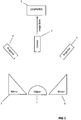
- an imaging system for imaging an object 1 in accordance with the invention comprises a camera 2 and one or more sources of structured light 3, 4 which may for example be projectors and lasers in combination with fringe gratings.
- the relative positions in three-dimensional space of camera 2 and sources of structured light 3, 4 are either known or may be determined, for example using a geometric approach to position determination, typically based upon imaging of known objects such as rigid grids from different orientations and solving an optimisation problem for possible object configurations and camera parameters. Examples of suitable calibration methods are described in Geng, J. Structured-light 3D surface imaging: a tutorial. Advances in Optics and Photonics, Vol. 3, Issue 2, p. 148 .
- the sources of structured light 3, 4 are arranged to project structured light on to the object 1 and the camera 2 is arranged to capture image data of the object 1 together with the projected structured light incident on the object 1.
- the sources of structured light 3, 4 may each project a sinusoidal pattern on to object 1 with the sinusoidal pattern projected by each projector having a different frequency or phase as described in detail below.
- One or more mirrors 5, 6 are also provided.
- the one or more mirrors 5, 6 provide additional camera field of view by reflecting light to the camera 2.
- the imaging system further comprises a computer 7 arranged to process the image data captured by the camera 2 as described in detail below.
- Figure 1A shows the computer 7 of Figure 1 in further detail.
- the computer comprises a CPU 7a which is configured to read and execute instructions stored in a volatile memory 7b which takes the form of a random access memory.
- the volatile memory 7b stores instructions for execution by the CPU 7a and data used by those instructions. For example, in use, image data generated by the camera 2 may be stored in the volatile memory 7b.
- the computer 7 further comprises non-volatile storage in the form of a hard disc drive 7c.
- the image data generated by the camera 2 may be stored on the hard disc drive 7c.
- the computer 7 further comprises an I/O interface 7d to which are connected peripheral devices used in connection with the computer 7. More particularly, a display 7e is configured so as to display output from the computer 7.
- the display 7e may, for example, display a representation of the image data. Additionally, the display 7e may display images generated by processing of the image data, for example as shown in Figures 4A to 4C .
- Input devices are also connected to the I/O interface 7d. Such input devices include a keyboard 7f and a mouse 7g which allow user interaction with the computer 7.
- display 7e may be a touch screen that may be used as an input device as well as a display device.
- a network interface 7h allows the computer 7 to be connected to an appropriate computer network so as to receive and transmit data from and to other computing devices.
- the CPU 7a, volatile memory 7b, hard disc drive 7c, I/O interface 7d, and network interface 7h, are connected together by a bus 7i.
- the direction of increasing phase of the sinusoidal pattern is defined as the direction in which phase values associated with the pattern as projected, and as viewed on a flat screen placed in front of the projector and orthogonal to the projector axis, increase and in which phase values in a direction orthogonal to the direction of increasing phase are constant.
- the sinusoidal pattern is generated based upon the cosine of phase values such that the pattern repeats in the direction of a first axis of the pattern whilst remaining constant in the direction of a second orthogonal axis of the pattern.
- the phase at a pixel is therefore a linear function of a coordinate along the first axis and the direction of increasing phase of the sinusoidal pattern is the direction of the first axis.
- the further frequency image data comprises image data representing the object and structured light incident on the object that is caused by the projection of a sinusoidal pattern p nm having frequency f m > f m-1 , with (f m / f m-1 ) * e ⁇ ⁇ , where e is the measurement error of the of system, and N m ⁇ 3 phase offsets ⁇ nm .
- each of the low frequency image data and further frequency image data may comprise N m images captured by camera 2, each of the images being captured during which a sinusoidal pattern having a respective frequency and a phase n is projected on to the object.
- An example of an object placed in the imaging system of the present invention is shown in Figure 3A and the same object having a relatively high frequency sinusoidal pattern projected thereon is shown in Figure 3B .
- a single image that represents the object may be generated in which structured light is projected on the object at more than one frequency simultaneously, for example by using a spectrally resolved camera and projector such that structured light projected on to the object at different frequencies simultaneously may be extracted from a single image.
- wrapped phase data ⁇ ( x , f )(mod2 ⁇ ), is generated for each of frequencies f m .
- the wrapped phase data is generated based upon the image data representing the object and structured light incident on the object caused by the projection of sinusoidal pattern p nm at each phase n according to (4) below.
- ⁇ n 1 N g n x _ , f cos 2 ⁇ n N
- the wrapped phase data ⁇ ( x , f )(mod2 ⁇ ) generally includes 2 ⁇ phase discontinuities caused by the periodic nature of the sinusoidal projected pattern.
- the wrapped phase data ⁇ ( x , f ) does not contain any phase discontinuities such that the image data at frequency f 1 provides the phase of each point in the imaged region.
- each pixel in the low frequency image data has a phase value - ⁇ ⁇ q ⁇ + ⁇ .
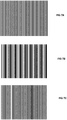
- Example phase maps representing the wrapped phase data are shown in Figures 4A , 4B and 4C for different frequencies.
- Figure 4A shows a wrapped phase map generated using a sinusoidal projected pattern having a wavelength of 1024 pixels and providing 0.78 waves per projected pattern in the imaged region.
- Figure 4B shows a wrapped phase map generated using a sinusoidal projected pattern having a wavelength of 11.3 pixels and providing 70.7 waves per projected pattern in the imaged region and
- Figure 4C shows a wrapped phase map generated using a sinusoidal projected pattern having a wavelength of 45.3 pixels and providing 18 waves per projected pattern in the imaged region.
- pixel values lie in the range (+ ⁇ ,- ⁇ ), irrespective of the phase range of the projected pattern. This is due to phase values that lie outside of the range (+ ⁇ ,- ⁇ ) being phase wrapped, which causes phase to become periodic as described above.
- phase values of the projected image between ⁇ and - ⁇ are unchanged by phase wrapping, phase values of ⁇ + d for d>2 ⁇ become - ⁇ + d in the phase wrapped image and phase values of - ⁇ - d become ⁇ -d in the phase wrapped image.
- phase wrapping can be seen in the wrapped phase maps as discrete changes in pixel values as the phase in the original projected pattern extends outside of the pixel range ( ⁇ , - ⁇ ) and appears as adjacent black and white pixels in regions that are in fact continuous in the imaged object.
- Figure 4B shows stripes in the image where adjacent pixels are black, representing a pixel value of - ⁇ and white representing a pixel value of ⁇ .
- Such wrapping events can also occur with isolated pixels which appear as isolated white pixels in a black region or as isolated black pixels in a white region.
- phase map generated at frequency f 1 does not include any phase wrapping events given that frequency f 1 is selected such that f 1 ⁇ 1 / d.
- phase error is relatively large at low frequencies relative to the phase values.
- phase is measured to an absolute error e that is approximately the same for all wrapped phase maps irrespective of pattern frequency.
- the range of phases of the unwrapped phase map increases as the frequency of the projected pattern increases due to the phase increasing by a factor of 2 ⁇ for each pattern repeat. The error e therefore decreases as a fraction of phase range as the pattern frequency increases such that height error associated with the phase error e also decreases.
- the wrapped phase data at frequency f 1 can be used as prior information to unwrap the wrapped phase data for higher frequencies, which include lower errors given the increased phase range as described above. That is, the wrapped phase data at frequency f 1 can be used to remove phase wrapping events in higher frequency wrapped phase data.
- the measured wrapped phase map ⁇ ( x ,f 2 )(mod 2 ⁇ ) can be compared with the simulated data to correct for measurement noise in ⁇ ( x ,f 2 ).
- the wrapped phase data for frequency f 2 is unwrapped based upon the wrapped phase data for frequency f 1 .
- steps S5 and S6 remaining unwrapped phase data, if any, are iteratively unwrapped based upon the preceding phase data in a corresponding manner. The process is repeated as necessary until the phase lies within the interval (- ⁇ , ⁇ ).
- the wrapped phase data for frequency f m is unwrapped based upon the unwrapped phase data for frequency f m-1 .
- an unwrapped high frequency phase map that contains relatively small error in a spatially independent manner. That is, the generation of an unwrapped high frequency phase of the present invention avoids the use of a spatial distribution of the wrapped phase data to determine locations of phase wrapping of prior art methods and accordingly avoids the propagation of errors in the determination of phase wrapping events through spatial regions of prior art methods.
- FIG. 5 A representation of the unwrapped phase data corresponding to the wrapped phase data of Figure 4B is shown in Figure 5 . It can be seen that the unwrapped phase data of Figure 5 does not include the stripes of the wrapped phase data of Figure 4B indicating that a number of phase discontinuities have been resolved in the unwrapped phase data.
- the highest frequency unwrapped phase data is processed using a general geometrical model to generate surface geometry information of the object and position data indicating relative positions of the camera and the source of structured light for the frequency.
- the surface geometry information may be generated using any geometrical method that is general.
- surface geometry information is generated based upon a geometric model in which relative locations of the components of the system are modelled and the model and the unwrapped phase are used in the generation of the surface geometry information.
- the general geometric model models the projected pattern as a continuous field in space projected from a pupil associated with the projector and the camera as a pupil with rays emanating from the camera pupil resulting in imaged pixels.
- x c _ + ⁇ _ ⁇ p _ ⁇ c _ ⁇ _ ⁇ r _ ⁇ r _ ⁇ where ⁇ is as in (10).
- ⁇ ⁇ 2 ⁇ f p _ ⁇ o _
- the spatial coordinates may be represented as a point cloud or a mesh format to allow visualisation of the object.
- An example point cloud is shown in Figure 8 and an example mesh format that has been generated using Meshlab is shown in Figure 9 .
- the structured light incident on the object is caused by the projection of a sinusoidal pattern.
- the sinusoidal pattern may be one or two dimensional and may comprise one or more sinusoidal wave patterns.
- the phase of the sinusoidal pattern may be defined by a non-linear function. Such a non-linear phase can reduce aliasing artefacts where the structured light is projected onto the imaged region at a relatively acute angle.
- wrapped phase data generated based upon a high frequency sinusoidal pattern having a frequency f m in the manner described above by imaging an object with the sinusoidal pattern incident upon the object at a plurality of phase offsets may be unwrapped using an encoding of the phase that is obtained based upon images of the object in which binary patterns are projected on to the object, the binary images being sufficient to provide information associating each image pixel of the imaged region with a pattern element of the pattern of the source of structured light. Examples of binary patterns are shown in Figures 7A-7C .
- Binary images can be used to encode the phase of an image by projecting a plurality of binary patterns, that is images in which image elements of the projected pattern are either black or white, on to the object and imaging the object whilst each pattern is incident on the object.
- Corresponding pixel values in the obtained images may then be assigned a value of 1 or 0, for example by first imaging the object whilst continuous light is projected into the region and additionally whilst no light is projected into the region to determine pixel values corresponding to Is and 0s, and the binary values combined to provide a binary encoding in which each pixel has an associated binary value that provides an association between the pixel and a phase value m associated with a wave of the plurality of waves of the high frequency sinusoidal pattern.
- Such a binary encoding provides an efficient encoding of the phase information of the high frequency sinusoidal pattern.
- a high frequency sinusoidal pattern having a frequency that is such that 256 waves are present in the projected pattern an 8 bit encoding can be used in which each image pixel in the binary encoding has an associated 8 bit value that is generated based upon 8 binary patterns projected on to the object to be imaged.
- the binary patterns projected onto the object to be imaged are selected in such a way that the 8 bit value of the binary encoding associated with each image pixel provides an association between each wave of the high frequency sinusoidal pattern with a pixel of the imaged region.
- the binary images and consequent binary encoding can be constructed to provide a value for each wave of the sinusoidal pattern.
- camera and projector defocus can be problematic for determining a binary value for a pixel as imaged pixels may be blurred such that determining whether the pixel has a black or white region of the binary pattern incident upon the corresponding part of the imaged region cannot readily be determined .
- Defocus can be mitigated by using a laser projection system as the source of the patterns incident on the object, however such laser projection systems are typically expensive.
- Defocus can additionally or alternatively be mitigated by using inverse Gray codings in which phases are encoded such that adjacent phases are encoded by values that differ by all but one value in the encoding and generating two encodings offset from one another by half the length of the sinusoid wave in the high frequency pattern.
- inverse Gray codings in which phases are encoded such that adjacent phases are encoded by values that differ by all but one value in the encoding and generating two encodings offset from one another by half the length of the sinusoid wave in the high frequency pattern.
- a phase m + 1 may be encoded by a binary value 11110111.
- the binary encoding for m differs from the encoding for phase m + 1 at all bits other than one (the right most bit).
- mirrors 5, 6 may be provided in the imaging system to provide additional field of view to the camera during image data capture.
- the virtual location of the virtual camera that is used in the generation of the surface geometry information is the reflection of the real camera about the plane of the mirror and can be determined based upon the known location of the mirror and the known location of the real camera.
- Phase data generated from light reflected in mirrors 5, 6 is then processed as if it is captured by the virtual camera in the same way as the image data that is not reflected (i.e. that is imaged directly by the camera) and can be combined with the image data that is not reflected.
- the virtual camera locations are modelled in the general geometric model described above by modelling the virtual camera location at a point corresponding to reflection of the real camera in the plane associated with the mirrors.
- Each of the image data generated based upon the real camera location and the virtual camera location have a common coordinate system such that the image data can be combined in a straightforward way by combining three-dimensional co-ordinate values generated from the image data both from reflected and directly imaged views into a single data set.
- the present invention allows the use of mirrors by removing the requirement of prior art systems that a cross-axis instrument geometry is used.
- the processing of phase data of the present invention allows arbitrary instrument geometries to be used which allows considerably more flexibility in the instrument arrangement but additionally allows the use of mirrors in which the mirrors are placed so as to effectively increase the camera field of view without the requiring that the virtual camera positions required by the use of mirrors satisfy the cross-axis instrument geometry.
- the use of mirrors increases the likelihood of imaging regions in the captured image data with discontinuities and prior art phase unwrapping techniques are generally less able to process image data with such discontinuities.
Landscapes
- Physics & Mathematics (AREA)
- Engineering & Computer Science (AREA)
- Computer Vision & Pattern Recognition (AREA)
- General Physics & Mathematics (AREA)
- Optics & Photonics (AREA)
- Theoretical Computer Science (AREA)
- Length Measuring Devices By Optical Means (AREA)
Claims (11)
- Verfahren zum Erzeugen von Oberflächengeometrieinformationen eines Objekts (1) in einer abgebildeten Region unter Verwendung eines Bildgebungssystems, das eine Kamera (2) und eine Quelle von strukturiertem Licht (3) umfasst, die eine Quelle einer Vielzahl von Lichtstrahlen umfasst, wobei das Verfahren Folgendes umfasst:Erhalten erster Bilddaten, die eine Vielzahl von Pixeln umfassen, wobei die ersten Bilddaten phasengefaltete Bilddaten umfassen, die das Objekt (1) und erstes auf das Objekt auftreffendes strukturiertes Licht repräsentieren, wobei das erste strukturierte Licht ein periodisches sinusförmiges Muster umfasst, das eine Vielzahl von Musterelementen umfasst und eine erste Raumfrequenz aufweist, die von der Quelle des strukturierten Lichts (3) projiziert wird;Erhalten zweiter Bilddaten, die eine Vielzahl von Pixeln umfassen, wobei die zweiten Bilddaten phasenentfaltete Bilddaten umfassen, die das Objekt (1) und zweites auf das Objekt auftreffendes strukturiertes Licht repräsentieren, das ein periodisches sinusförmiges Muster umfasst, das eine Vielzahl von Musterelementen umfasst und eine zweite Raumfrequenz aufweist, die von der Quelle des strukturierten Lichts (3) projiziert wird;wobei die zweiten Bilddaten auf Basis einer Phasenentfaltung unter Verwendung dritter Bilddaten erzeugt werden, die phasengefaltete Bilddaten umfassen, die das Objekt (1) und drittes auf das Objekt auftreffendes strukturiertes Licht repräsentieren, das ein periodisches sinusförmiges Muster umfasst, das eine Vielzahl von Musterelementen umfasst und eine dritte Raumfrequenz aufweist, die von der Quelle des strukturierten Lichts (3) projiziert wird;Verarbeiten der ersten Bilddaten, um eine Beziehung zwischen jedem der Vielzahl von Bildpixeln der ersten Bilddaten und einem Musterelement des Musters des ersten strukturierten Lichts, das von der Quelle von strukturiertem Licht (3) projiziert wird, zu bestimmen, wobei das Verarbeiten ein Entfalten der Phase der ersten Bilddaten unter Verwendung der zweiten Bilddaten umfasst; undErzeugen der Oberflächengeometrieinformationen des Objekts (1) auf Basis der bestimmten Beziehung und Positionsdaten, die relative Raumpositionen der Kamera (2) und der Quelle von strukturiertem Licht (3) anzeigen;wobei das erste strukturierte Licht, das zweite strukturierte Licht und das dritte strukturierte Licht, in drei oder mehr Phasenversatzen auf das Objekt auftreffen;wobei die Raumfrequenz des ersten strukturierten Lichts größer ist als die Raumfrequenz des zweiten strukturierten Lichts und die Raumfrequenz des zweiten strukturierten Lichts größer ist als die Raumfrequenz des dritten strukturierten Lichts undwobei die dritte Raumfrequenz kleiner ist als 1/d, wobei d eine Größe des Projektionsfeldes in der Ebene von Interesse ist, die dem abzubildenden Bereich entspricht, in den die Vielzahl von Musterelementen projiziert werden.
- Verfahren nach Anspruch 1, wobei das Bildgebungssystem ferner mindestens eine reflektierende Oberfläche (5, 6) umfasst, die sich in der abgebildeten Region befindet, um wahlweise ein Sichtfeld des Objekts (1) zu maximieren, wobei die einzelnen Bilddaten ferner Bilddaten umfassen, die das Objekt (1), das von der mindestens einen reflektierenden Oberfläche (5, 6) reflektiert wird, repräsentieren.
- Verfahren nach Anspruch 2, wobei das Erzeugen der Oberflächengeometrieinformationen des Objekts (1) das Kombinieren der Bilddaten, die das Objekt (1), das von der mindestens einen reflektierenden Oberfläche (5, 6) reflektiert wird, repräsentieren, und von Bilddaten, die das direkt abgebildete Objekt repräsentieren, umfasst.
- Verfahren nach Anspruch 3, wobei das Kombinieren Folgendes umfasst:Erzeugen von Positionsdaten, die einen virtuellen Kamerastandort anzeigen, der mit jeder der mindestens einen reflektierenden Oberfläche (5, 6) verknüpft ist; undKombinieren der Bilddaten auf Basis der Positionsdaten, die virtuelle Kamerastandorte anzeigen, und der Positionsdaten, die relative Raumpositionen der Kamera (2) und der Quelle von strukturiertem Licht (3) anzeigen, und wahlweise ferner das Erzeugen der Positionsdaten, die virtuelle Kamerastandorte anzeigen, unter Verwendung des Bildgebungssystems umfassend.
- Verfahren nach einem der vorhergehenden Ansprüche, wobei das Erzeugen der Oberflächengeometrieinformationen des Objekts (1) auf Basis der bestimmten Beziehung und Positionsdaten, die relative Raumpositionen der Kamera (2) und der Quelle von strukturiertem Licht (3) anzeigen, Folgendes umfasst:
Verarbeiten der bestimmten Beziehung auf Basis eines geometrischen Modells, in dem relative Raumpositionen der Kamera (2) und der Quelle von strukturiertem Licht (3) modelliert sind. - Verfahren nach einem der vorhergehenden Ansprüche, wobei die zweiten Bilddaten auf Basis der dritten Bilddaten und weiterer Bilddaten, die Bilddaten umfassen, die das Objekt und weiteres auf das Objekt auftreffendes strukturiertes Licht repräsentieren, erzeugt werden, wobei das weitere strukturierte Licht ein periodisches Muster umfasst, das eine weitere Raumfrequenz aufweist, die von der Quelle von strukturiertem Licht (3) projiziert wird, wobei die zweite Raumfrequenz größer ist als die weitere Raumfrequenz;
wobei die zweite Raumfrequenz oder die weitere Raumfrequenz wahlweise eine Raumfrequenz aufweist, die kleiner als eine Wiederholung des Musters in der abgebildeten Region ist oder mit dieser übereinstimmt. - Verfahren nach Anspruch 6, wobei das Verarbeiten der ersten Bilddaten auf Basis der zweiten Bilddaten, um eine Beziehung zwischen jedem Bildpixel der ersten Bilddaten und dem ersten strukturierten Licht, das von der Quelle von strukturiertem Licht (3) projiziert wird, zu bestimmen, auf der ersten Raumfrequenz und einer mit den zweiten Bilddaten verknüpften Raumfrequenz basiert.
- Verfahren nach einem der vorstehenden Ansprüche,
wobei die ersten und/oder die zweiten Bilddaten auf Basis einer Vielzahl von Bildern des Objekts und von auf das Objekt auftreffendem strukturiertem Licht erzeugt werden, wobei das Muster in jedem der Vielzahl von Bildern einen jeweiligen Phasenversatz aufweist und wahlweise wobei eine Vielzahl von Phasenversatzen, die mit den ersten Bilddaten verknüpft sind, größer ist als eine Vielzahl von Phasenversatzen, die mit den zweiten Bilddaten verknüpft sind. - Verfahren nach einem der vorhergehenden Ansprüche, wobei die Quelle von strukturiertem Licht (3) eine Vielzahl von Quellen von strukturiertem Licht (3, 4) umfasst, wobei jede der Vielzahl von Quellen von strukturiertem Licht angeordnet ist, strukturiertes Licht mindestens auf einen Abschnitt des Objekts zu projizieren, der sich von anderen der Vielzahl von Quellen von strukturiertem Licht (3, 4) unterscheidet; und/oder
wobei ein erstes des strukturierten Lichts Licht einer ersten Farbe umfasst und ein zweites des strukturierten Lichts Licht einer zweiten Farbe umfasst und/oder
wobei die Quelle von strukturiertem Licht aus der Gruppe ausgewählt ist, die aus Folgendem besteht: einem Laser; einer Lichtquelle in Verbindung mit einem Randgitter und einem Projektor. - Computerlesbares Medium, auf dem sich ein Computerprogramm befindet, das computerlesbare Anweisungen umfasst, die dazu ausgelegt sind zu bewirken, dass ein Computer ein Verfahren nach einem der Ansprüche 1 bis 9 umsetzt.
- Computervorrichtung (7) zum Erzeugen von Oberflächengeometrieinformationen eines Objekts in einer abgebildeten Region unter Verwendung eines Bildgebungssystems, das eine Kamera (20) und eine Quelle von strukturiertem Licht (3) umfasst, Folgendes umfassend:einen Speicher, der prozessorlesbare Anweisungen speichert; undeinen Prozessor, der angeordnet ist, in dem Speicher gespeicherte Anweisungen zu lesen und auszuführen;wobei die prozessorlesbaren Anweisungen Anweisungen umfassen, die angeordnet sind, den Computer zu steuern, um ein Verfahren nach einem der Ansprüche 1 bis 9 umzusetzen.
Applications Claiming Priority (2)
| Application Number | Priority Date | Filing Date | Title |
|---|---|---|---|
| GBGB1222361.6A GB201222361D0 (en) | 2012-12-12 | 2012-12-12 | Surface geometry imaging |
| PCT/GB2013/053236 WO2014091214A1 (en) | 2012-12-12 | 2013-12-09 | Surface geometry imaging |
Publications (2)
| Publication Number | Publication Date |
|---|---|
| EP2932468A1 EP2932468A1 (de) | 2015-10-21 |
| EP2932468B1 true EP2932468B1 (de) | 2018-08-22 |
Family
ID=47602458
Family Applications (1)
| Application Number | Title | Priority Date | Filing Date |
|---|---|---|---|
| EP13805493.7A Not-in-force EP2932468B1 (de) | 2012-12-12 | 2013-12-09 | Oberflächengeometrieabbildung |
Country Status (5)
| Country | Link |
|---|---|
| US (1) | US9879985B2 (de) |
| EP (1) | EP2932468B1 (de) |
| CN (1) | CN104981842B (de) |
| GB (1) | GB201222361D0 (de) |
| WO (1) | WO2014091214A1 (de) |
Families Citing this family (28)
| Publication number | Priority date | Publication date | Assignee | Title |
|---|---|---|---|---|
| WO2015134795A2 (en) | 2014-03-05 | 2015-09-11 | Smart Picture Technologies, Inc. | Method and system for 3d capture based on structure from motion with pose detection tool |
| US20150369593A1 (en) * | 2014-06-19 | 2015-12-24 | Kari MYLLYKOSKI | Orthographic image capture system |
| EP3032241B1 (de) | 2014-12-11 | 2023-03-01 | X-Rite Europe GmbH | Verfahren und vorrichtung zur digitalisierung des aussehens eines echten materials |
| WO2016145582A1 (zh) * | 2015-03-13 | 2016-09-22 | 香港应用科技研究院有限公司 | 相位偏移校准方法、3d形状检测的方法、系统及投影系统 |
| CN104713497B (zh) * | 2015-03-13 | 2017-07-04 | 香港应用科技研究院有限公司 | 相位偏移校准方法、3d形状检测的方法、系统及投影系统 |
| US10083522B2 (en) | 2015-06-19 | 2018-09-25 | Smart Picture Technologies, Inc. | Image based measurement system |
| JP6371742B2 (ja) * | 2015-09-03 | 2018-08-08 | キヤノン株式会社 | 計測装置および取得方法 |
| KR102368597B1 (ko) * | 2015-11-11 | 2022-03-02 | 삼성전자주식회사 | 영상 촬영 장치 및 이의 제어 방법 |
| US10037612B2 (en) * | 2015-12-28 | 2018-07-31 | Empire Technology Development Llc | Three dimensional data acquisition with orthogonal composite pattern for structured light illuminated vision |
| CN108616727A (zh) * | 2016-12-23 | 2018-10-02 | 光宝电子(广州)有限公司 | 基于结构光的曝光控制方法及曝光控制装置 |
| JP6673266B2 (ja) * | 2017-03-08 | 2020-03-25 | オムロン株式会社 | 相互反射検出装置、相互反射検出方法、およびプログラム |
| WO2018173031A1 (en) * | 2017-03-24 | 2018-09-27 | Ariel Scientific Innovations Ltd. | System and method for compensating diffraction |
| CN106705896B (zh) * | 2017-03-29 | 2022-08-23 | 江苏大学 | 一种基于单摄像机全方位主动视觉的电连接器壳体缺陷检测装置及方法 |
| CN107271445B (zh) * | 2017-05-16 | 2020-10-16 | 广州视源电子科技股份有限公司 | 一种缺陷检测方法及装置 |
| US10304254B2 (en) | 2017-08-08 | 2019-05-28 | Smart Picture Technologies, Inc. | Method for measuring and modeling spaces using markerless augmented reality |
| WO2019066724A1 (en) * | 2017-09-27 | 2019-04-04 | Ams Sensors Singapore Pte. Ltd. | LIGHT PROJECTION SYSTEMS |
| GB201721451D0 (en) * | 2017-12-20 | 2018-01-31 | Univ Manchester | Apparatus and method for determining spectral information |
| JP6611872B2 (ja) * | 2018-07-13 | 2019-11-27 | キヤノン株式会社 | 計測装置 |
| AU2018220142A1 (en) * | 2018-08-24 | 2020-03-12 | Canon Kabushiki Kaisha | Method and system for reproducing visual content |
| CN109242892B (zh) | 2018-09-12 | 2019-11-12 | 北京字节跳动网络技术有限公司 | 用于确定图像间的几何变换关系的方法和装置 |
| US11524136B2 (en) * | 2018-12-24 | 2022-12-13 | Biosense Webster (Israel) Ltd. | Non-invasive measurement of the pitch of a braid |
| EP3966789A4 (de) | 2019-05-10 | 2022-06-29 | Smart Picture Technologies, Inc. | Verfahren und systeme zum messen und modellieren von räumen unter verwendung eines computergestützten prozesses der erweiterten realität |
| EP3745081B1 (de) * | 2019-05-28 | 2023-03-22 | Tecan Trading Ag | Positionsdetektor und verfahren zur 3d-positionsbestimmung |
| EP3926295B1 (de) * | 2020-06-16 | 2024-07-31 | VITRONIC Dr.-Ing. Stein Bildverarbeitungssysteme GmbH | Verfahren zum erkennen einer verzerrung eines ein codewort definierenden lichtmusters sowie lichtmuster |
| CN221786313U (zh) * | 2020-11-17 | 2024-10-01 | 西安大医集团股份有限公司 | 光学监控系统及放射治疗设备 |
| CN114018819B (zh) * | 2021-03-22 | 2022-11-11 | 北京航空航天大学 | 基于空间频域成像的光学特性测量方法、装置及系统 |
| CN118463854B (zh) * | 2024-05-08 | 2025-01-14 | 广州市斯睿特智能科技有限公司 | 一种基于多频相位移动的结构光三维成像方法及相关装置 |
| CN118844982B (zh) * | 2024-09-27 | 2024-12-06 | 浙江杜比医疗科技有限公司 | 一种乳房形貌测量方法、装置、设备及介质 |
Family Cites Families (8)
| Publication number | Priority date | Publication date | Assignee | Title |
|---|---|---|---|---|
| US8224064B1 (en) * | 2003-05-21 | 2012-07-17 | University Of Kentucky Research Foundation, Inc. | System and method for 3D imaging using structured light illumination |
| WO2007050776A2 (en) | 2005-10-25 | 2007-05-03 | University Of Kentucky Research Foundation | System and method for 3d imaging using structured light illumination |
| CN101821579B (zh) * | 2007-08-17 | 2013-01-23 | 瑞尼斯豪公司 | 相位分析测量装置和方法 |
| GB0915904D0 (en) * | 2009-09-11 | 2009-10-14 | Renishaw Plc | Non-contact object inspection |
| US20110080471A1 (en) * | 2009-10-06 | 2011-04-07 | Iowa State University Research Foundation, Inc. | Hybrid method for 3D shape measurement |
| EP2763591A4 (de) * | 2011-10-09 | 2015-05-06 | Clear Guide Medical Llc | Interventionelle in-situ-bildführung mittels fusion von ultraschall-video |
| US9383576B2 (en) * | 2012-07-17 | 2016-07-05 | Rachel Andreasen | Apparatus and method for a flexible adaptive telescope mirror |
| US20140152769A1 (en) * | 2012-12-05 | 2014-06-05 | Paul Atwell | Three-dimensional scanner and method of operation |
-
2012
- 2012-12-12 GB GBGB1222361.6A patent/GB201222361D0/en not_active Ceased
-
2013
- 2013-12-09 EP EP13805493.7A patent/EP2932468B1/de not_active Not-in-force
- 2013-12-09 US US14/651,206 patent/US9879985B2/en not_active Expired - Fee Related
- 2013-12-09 WO PCT/GB2013/053236 patent/WO2014091214A1/en not_active Ceased
- 2013-12-09 CN CN201380072838.5A patent/CN104981842B/zh not_active Expired - Fee Related
Non-Patent Citations (1)
| Title |
|---|
| None * |
Also Published As
| Publication number | Publication date |
|---|---|
| US9879985B2 (en) | 2018-01-30 |
| EP2932468A1 (de) | 2015-10-21 |
| WO2014091214A1 (en) | 2014-06-19 |
| CN104981842A (zh) | 2015-10-14 |
| GB201222361D0 (en) | 2013-01-23 |
| US20150330775A1 (en) | 2015-11-19 |
| CN104981842B (zh) | 2019-05-28 |
Similar Documents
| Publication | Publication Date | Title |
|---|---|---|
| EP2932468B1 (de) | Oberflächengeometrieabbildung | |
| US8605983B2 (en) | Non-contact probe | |
| Jia et al. | Two-step triangular-pattern phase-shifting method for three-dimensional object-shape measurement | |
| CN106802137B (zh) | 一种相位展开方法及系统 | |
| JP2013539147A5 (de) | ||
| CN106257995A (zh) | 一种结构光场三维成像方法及其系统 | |
| Zhang et al. | Three-dimensional shape measurement using a structured light system with dual cameras | |
| CN116399227B (zh) | 一种基于mems振镜的结构光三维扫描系统标定方法 | |
| CN107810384B (zh) | 条纹投影方法、条纹投影装置和计算机程序产品 | |
| Jiang et al. | Absolute phase unwrapping for dual-camera system without embedding statistical features | |
| US10559085B2 (en) | Devices, systems, and methods for reconstructing the three-dimensional shapes of objects | |
| Yu et al. | Quasi-pixelwise motion compensation for 4-step phase-shifting profilometry based on a phase error estimation | |
| Ozendi et al. | A point cloud filtering method based on anisotropic error model | |
| CN114166150B (zh) | 一种条纹反射三维测量方法、系统及存储介质 | |
| Drouin et al. | Active 3D imaging systems | |
| RU2573767C1 (ru) | Устройство трехмерного сканирования сцены с неламбертовыми эффектами освещения | |
| Dhillon et al. | Geometric and radiometric estimation in a structured-light 3D scanner | |
| Breitbarth et al. | Phase unwrapping of fringe images for dynamic 3D measurements without additional pattern projection | |
| CN113375600B (zh) | 一种三维测量方法、装置和电子设备 | |
| KR101874486B1 (ko) | 깊이 영상의 깊이 값을 복원하는 방법 및 장치 | |
| Maimone | Characterizing stereo matching problems using local spatial frequency | |
| Gupta | Gray code composite pattern structured light illumination | |
| Ozendi et al. | Stochastic surface mesh reconstruction | |
| Ishiyama et al. | Precise 3-d measurement using uncalibrated pattern projection | |
| Altalib | Depth map extraction using structured light |
Legal Events
| Date | Code | Title | Description |
|---|---|---|---|
| PUAI | Public reference made under article 153(3) epc to a published international application that has entered the european phase |
Free format text: ORIGINAL CODE: 0009012 |
|
| 17P | Request for examination filed |
Effective date: 20150608 |
|
| AK | Designated contracting states |
Kind code of ref document: A1 Designated state(s): AL AT BE BG CH CY CZ DE DK EE ES FI FR GB GR HR HU IE IS IT LI LT LU LV MC MK MT NL NO PL PT RO RS SE SI SK SM TR |
|
| AX | Request for extension of the european patent |
Extension state: BA ME |
|
| DAX | Request for extension of the european patent (deleted) | ||
| 17Q | First examination report despatched |
Effective date: 20160331 |
|
| REG | Reference to a national code |
Ref country code: DE Ref legal event code: R079 Ref document number: 602013042481 Country of ref document: DE Free format text: PREVIOUS MAIN CLASS: G06T0007000000 Ipc: G06T0007521000 |
|
| GRAP | Despatch of communication of intention to grant a patent |
Free format text: ORIGINAL CODE: EPIDOSNIGR1 |
|
| RIC1 | Information provided on ipc code assigned before grant |
Ipc: G06T 7/521 20170101AFI20180322BHEP |
|
| INTG | Intention to grant announced |
Effective date: 20180420 |
|
| GRAS | Grant fee paid |
Free format text: ORIGINAL CODE: EPIDOSNIGR3 |
|
| GRAA | (expected) grant |
Free format text: ORIGINAL CODE: 0009210 |
|
| AK | Designated contracting states |
Kind code of ref document: B1 Designated state(s): AL AT BE BG CH CY CZ DE DK EE ES FI FR GB GR HR HU IE IS IT LI LT LU LV MC MK MT NL NO PL PT RO RS SE SI SK SM TR |
|
| REG | Reference to a national code |
Ref country code: GB Ref legal event code: FG4D |
|
| REG | Reference to a national code |
Ref country code: CH Ref legal event code: EP |
|
| REG | Reference to a national code |
Ref country code: AT Ref legal event code: REF Ref document number: 1033361 Country of ref document: AT Kind code of ref document: T Effective date: 20180915 |
|
| REG | Reference to a national code |
Ref country code: IE Ref legal event code: FG4D |
|
| REG | Reference to a national code |
Ref country code: DE Ref legal event code: R096 Ref document number: 602013042481 Country of ref document: DE |
|
| REG | Reference to a national code |
Ref country code: NL Ref legal event code: MP Effective date: 20180822 |
|
| REG | Reference to a national code |
Ref country code: LT Ref legal event code: MG4D |
|
| PG25 | Lapsed in a contracting state [announced via postgrant information from national office to epo] |
Ref country code: LT Free format text: LAPSE BECAUSE OF FAILURE TO SUBMIT A TRANSLATION OF THE DESCRIPTION OR TO PAY THE FEE WITHIN THE PRESCRIBED TIME-LIMIT Effective date: 20180822 Ref country code: FI Free format text: LAPSE BECAUSE OF FAILURE TO SUBMIT A TRANSLATION OF THE DESCRIPTION OR TO PAY THE FEE WITHIN THE PRESCRIBED TIME-LIMIT Effective date: 20180822 Ref country code: NL Free format text: LAPSE BECAUSE OF FAILURE TO SUBMIT A TRANSLATION OF THE DESCRIPTION OR TO PAY THE FEE WITHIN THE PRESCRIBED TIME-LIMIT Effective date: 20180822 Ref country code: BG Free format text: LAPSE BECAUSE OF FAILURE TO SUBMIT A TRANSLATION OF THE DESCRIPTION OR TO PAY THE FEE WITHIN THE PRESCRIBED TIME-LIMIT Effective date: 20181122 Ref country code: RS Free format text: LAPSE BECAUSE OF FAILURE TO SUBMIT A TRANSLATION OF THE DESCRIPTION OR TO PAY THE FEE WITHIN THE PRESCRIBED TIME-LIMIT Effective date: 20180822 Ref country code: NO Free format text: LAPSE BECAUSE OF FAILURE TO SUBMIT A TRANSLATION OF THE DESCRIPTION OR TO PAY THE FEE WITHIN THE PRESCRIBED TIME-LIMIT Effective date: 20181122 Ref country code: IS Free format text: LAPSE BECAUSE OF FAILURE TO SUBMIT A TRANSLATION OF THE DESCRIPTION OR TO PAY THE FEE WITHIN THE PRESCRIBED TIME-LIMIT Effective date: 20181222 Ref country code: GR Free format text: LAPSE BECAUSE OF FAILURE TO SUBMIT A TRANSLATION OF THE DESCRIPTION OR TO PAY THE FEE WITHIN THE PRESCRIBED TIME-LIMIT Effective date: 20181123 Ref country code: SE Free format text: LAPSE BECAUSE OF FAILURE TO SUBMIT A TRANSLATION OF THE DESCRIPTION OR TO PAY THE FEE WITHIN THE PRESCRIBED TIME-LIMIT Effective date: 20180822 |
|
| REG | Reference to a national code |
Ref country code: AT Ref legal event code: MK05 Ref document number: 1033361 Country of ref document: AT Kind code of ref document: T Effective date: 20180822 |
|
| PG25 | Lapsed in a contracting state [announced via postgrant information from national office to epo] |
Ref country code: HR Free format text: LAPSE BECAUSE OF FAILURE TO SUBMIT A TRANSLATION OF THE DESCRIPTION OR TO PAY THE FEE WITHIN THE PRESCRIBED TIME-LIMIT Effective date: 20180822 Ref country code: LV Free format text: LAPSE BECAUSE OF FAILURE TO SUBMIT A TRANSLATION OF THE DESCRIPTION OR TO PAY THE FEE WITHIN THE PRESCRIBED TIME-LIMIT Effective date: 20180822 Ref country code: AL Free format text: LAPSE BECAUSE OF FAILURE TO SUBMIT A TRANSLATION OF THE DESCRIPTION OR TO PAY THE FEE WITHIN THE PRESCRIBED TIME-LIMIT Effective date: 20180822 |
|
| PGFP | Annual fee paid to national office [announced via postgrant information from national office to epo] |
Ref country code: FR Payment date: 20181218 Year of fee payment: 6 Ref country code: GB Payment date: 20181219 Year of fee payment: 6 |
|
| PG25 | Lapsed in a contracting state [announced via postgrant information from national office to epo] |
Ref country code: CZ Free format text: LAPSE BECAUSE OF FAILURE TO SUBMIT A TRANSLATION OF THE DESCRIPTION OR TO PAY THE FEE WITHIN THE PRESCRIBED TIME-LIMIT Effective date: 20180822 Ref country code: ES Free format text: LAPSE BECAUSE OF FAILURE TO SUBMIT A TRANSLATION OF THE DESCRIPTION OR TO PAY THE FEE WITHIN THE PRESCRIBED TIME-LIMIT Effective date: 20180822 Ref country code: EE Free format text: LAPSE BECAUSE OF FAILURE TO SUBMIT A TRANSLATION OF THE DESCRIPTION OR TO PAY THE FEE WITHIN THE PRESCRIBED TIME-LIMIT Effective date: 20180822 Ref country code: PL Free format text: LAPSE BECAUSE OF FAILURE TO SUBMIT A TRANSLATION OF THE DESCRIPTION OR TO PAY THE FEE WITHIN THE PRESCRIBED TIME-LIMIT Effective date: 20180822 Ref country code: RO Free format text: LAPSE BECAUSE OF FAILURE TO SUBMIT A TRANSLATION OF THE DESCRIPTION OR TO PAY THE FEE WITHIN THE PRESCRIBED TIME-LIMIT Effective date: 20180822 Ref country code: IT Free format text: LAPSE BECAUSE OF FAILURE TO SUBMIT A TRANSLATION OF THE DESCRIPTION OR TO PAY THE FEE WITHIN THE PRESCRIBED TIME-LIMIT Effective date: 20180822 Ref country code: AT Free format text: LAPSE BECAUSE OF FAILURE TO SUBMIT A TRANSLATION OF THE DESCRIPTION OR TO PAY THE FEE WITHIN THE PRESCRIBED TIME-LIMIT Effective date: 20180822 |
|
| PGFP | Annual fee paid to national office [announced via postgrant information from national office to epo] |
Ref country code: DE Payment date: 20181220 Year of fee payment: 6 |
|
| REG | Reference to a national code |
Ref country code: DE Ref legal event code: R097 Ref document number: 602013042481 Country of ref document: DE |
|
| PG25 | Lapsed in a contracting state [announced via postgrant information from national office to epo] |
Ref country code: DK Free format text: LAPSE BECAUSE OF FAILURE TO SUBMIT A TRANSLATION OF THE DESCRIPTION OR TO PAY THE FEE WITHIN THE PRESCRIBED TIME-LIMIT Effective date: 20180822 Ref country code: SM Free format text: LAPSE BECAUSE OF FAILURE TO SUBMIT A TRANSLATION OF THE DESCRIPTION OR TO PAY THE FEE WITHIN THE PRESCRIBED TIME-LIMIT Effective date: 20180822 Ref country code: SK Free format text: LAPSE BECAUSE OF FAILURE TO SUBMIT A TRANSLATION OF THE DESCRIPTION OR TO PAY THE FEE WITHIN THE PRESCRIBED TIME-LIMIT Effective date: 20180822 |
|
| PLBE | No opposition filed within time limit |
Free format text: ORIGINAL CODE: 0009261 |
|
| STAA | Information on the status of an ep patent application or granted ep patent |
Free format text: STATUS: NO OPPOSITION FILED WITHIN TIME LIMIT |
|
| 26N | No opposition filed |
Effective date: 20190523 |
|
| REG | Reference to a national code |
Ref country code: CH Ref legal event code: PL |
|
| PG25 | Lapsed in a contracting state [announced via postgrant information from national office to epo] |
Ref country code: MC Free format text: LAPSE BECAUSE OF FAILURE TO SUBMIT A TRANSLATION OF THE DESCRIPTION OR TO PAY THE FEE WITHIN THE PRESCRIBED TIME-LIMIT Effective date: 20180822 Ref country code: SI Free format text: LAPSE BECAUSE OF FAILURE TO SUBMIT A TRANSLATION OF THE DESCRIPTION OR TO PAY THE FEE WITHIN THE PRESCRIBED TIME-LIMIT Effective date: 20180822 Ref country code: LU Free format text: LAPSE BECAUSE OF NON-PAYMENT OF DUE FEES Effective date: 20181209 |
|
| REG | Reference to a national code |
Ref country code: IE Ref legal event code: MM4A |
|
| REG | Reference to a national code |
Ref country code: BE Ref legal event code: MM Effective date: 20181231 |
|
| PG25 | Lapsed in a contracting state [announced via postgrant information from national office to epo] |
Ref country code: IE Free format text: LAPSE BECAUSE OF NON-PAYMENT OF DUE FEES Effective date: 20181209 |
|
| PG25 | Lapsed in a contracting state [announced via postgrant information from national office to epo] |
Ref country code: BE Free format text: LAPSE BECAUSE OF NON-PAYMENT OF DUE FEES Effective date: 20181231 |
|
| PG25 | Lapsed in a contracting state [announced via postgrant information from national office to epo] |
Ref country code: CH Free format text: LAPSE BECAUSE OF NON-PAYMENT OF DUE FEES Effective date: 20181231 Ref country code: LI Free format text: LAPSE BECAUSE OF NON-PAYMENT OF DUE FEES Effective date: 20181231 |
|
| PG25 | Lapsed in a contracting state [announced via postgrant information from national office to epo] |
Ref country code: MT Free format text: LAPSE BECAUSE OF NON-PAYMENT OF DUE FEES Effective date: 20181209 |
|
| PG25 | Lapsed in a contracting state [announced via postgrant information from national office to epo] |
Ref country code: TR Free format text: LAPSE BECAUSE OF FAILURE TO SUBMIT A TRANSLATION OF THE DESCRIPTION OR TO PAY THE FEE WITHIN THE PRESCRIBED TIME-LIMIT Effective date: 20180822 |
|
| PG25 | Lapsed in a contracting state [announced via postgrant information from national office to epo] |
Ref country code: PT Free format text: LAPSE BECAUSE OF FAILURE TO SUBMIT A TRANSLATION OF THE DESCRIPTION OR TO PAY THE FEE WITHIN THE PRESCRIBED TIME-LIMIT Effective date: 20180822 |
|
| PG25 | Lapsed in a contracting state [announced via postgrant information from national office to epo] |
Ref country code: MK Free format text: LAPSE BECAUSE OF NON-PAYMENT OF DUE FEES Effective date: 20180822 Ref country code: CY Free format text: LAPSE BECAUSE OF FAILURE TO SUBMIT A TRANSLATION OF THE DESCRIPTION OR TO PAY THE FEE WITHIN THE PRESCRIBED TIME-LIMIT Effective date: 20180822 Ref country code: HU Free format text: LAPSE BECAUSE OF FAILURE TO SUBMIT A TRANSLATION OF THE DESCRIPTION OR TO PAY THE FEE WITHIN THE PRESCRIBED TIME-LIMIT; INVALID AB INITIO Effective date: 20131209 |
|
| REG | Reference to a national code |
Ref country code: DE Ref legal event code: R119 Ref document number: 602013042481 Country of ref document: DE |
|
| GBPC | Gb: european patent ceased through non-payment of renewal fee |
Effective date: 20191209 |
|
| PG25 | Lapsed in a contracting state [announced via postgrant information from national office to epo] |
Ref country code: FR Free format text: LAPSE BECAUSE OF NON-PAYMENT OF DUE FEES Effective date: 20191231 Ref country code: DE Free format text: LAPSE BECAUSE OF NON-PAYMENT OF DUE FEES Effective date: 20200701 Ref country code: GB Free format text: LAPSE BECAUSE OF NON-PAYMENT OF DUE FEES Effective date: 20191209 |