EP2932113B1 - Thrust washer - Google Patents
Thrust washer Download PDFInfo
- Publication number
- EP2932113B1 EP2932113B1 EP13805481.2A EP13805481A EP2932113B1 EP 2932113 B1 EP2932113 B1 EP 2932113B1 EP 13805481 A EP13805481 A EP 13805481A EP 2932113 B1 EP2932113 B1 EP 2932113B1
- Authority
- EP
- European Patent Office
- Prior art keywords
- polymer
- thrust washer
- substrate
- layer
- axial
- Prior art date
- Legal status (The legal status is an assumption and is not a legal conclusion. Google has not performed a legal analysis and makes no representation as to the accuracy of the status listed.)
- Active
Links
- 229920000642 polymer Polymers 0.000 claims description 81
- 239000000758 substrate Substances 0.000 claims description 70
- 238000009826 distribution Methods 0.000 claims description 42
- 239000003921 oil Substances 0.000 description 41
- 229910052751 metal Inorganic materials 0.000 description 24
- 239000002184 metal Substances 0.000 description 24
- 238000000034 method Methods 0.000 description 23
- 238000003754 machining Methods 0.000 description 15
- 239000000463 material Substances 0.000 description 15
- 238000004519 manufacturing process Methods 0.000 description 12
- 238000000151 deposition Methods 0.000 description 10
- YVIMHTIMVIIXBQ-UHFFFAOYSA-N [SnH3][Al] Chemical compound [SnH3][Al] YVIMHTIMVIIXBQ-UHFFFAOYSA-N 0.000 description 9
- 239000004642 Polyimide Substances 0.000 description 8
- 150000001408 amides Chemical class 0.000 description 8
- 239000011159 matrix material Substances 0.000 description 8
- 229920001721 polyimide Polymers 0.000 description 8
- 239000002699 waste material Substances 0.000 description 8
- WSFSSNUMVMOOMR-UHFFFAOYSA-N Formaldehyde Chemical compound O=C WSFSSNUMVMOOMR-UHFFFAOYSA-N 0.000 description 6
- 239000004033 plastic Substances 0.000 description 6
- 229920003023 plastic Polymers 0.000 description 6
- 229910000831 Steel Inorganic materials 0.000 description 5
- 239000002131 composite material Substances 0.000 description 5
- 229920002313 fluoropolymer Polymers 0.000 description 5
- 239000004811 fluoropolymer Substances 0.000 description 5
- 239000002861 polymer material Substances 0.000 description 5
- 239000010959 steel Substances 0.000 description 5
- 239000000843 powder Substances 0.000 description 4
- 239000011347 resin Substances 0.000 description 4
- 229920005989 resin Polymers 0.000 description 4
- 206010011906 Death Diseases 0.000 description 3
- 239000010687 lubricating oil Substances 0.000 description 3
- 239000010814 metallic waste Substances 0.000 description 3
- 238000007649 pad printing Methods 0.000 description 3
- 239000004810 polytetrafluoroethylene Substances 0.000 description 3
- 229920001343 polytetrafluoroethylene Polymers 0.000 description 3
- 238000007650 screen-printing Methods 0.000 description 3
- 238000005507 spraying Methods 0.000 description 3
- 239000004925 Acrylic resin Substances 0.000 description 2
- VYPSYNLAJGMNEJ-UHFFFAOYSA-N Silicium dioxide Chemical compound O=[Si]=O VYPSYNLAJGMNEJ-UHFFFAOYSA-N 0.000 description 2
- 238000000429 assembly Methods 0.000 description 2
- 230000000712 assembly Effects 0.000 description 2
- 238000010276 construction Methods 0.000 description 2
- 230000008021 deposition Effects 0.000 description 2
- 238000004049 embossing Methods 0.000 description 2
- 239000003822 epoxy resin Substances 0.000 description 2
- 239000012535 impurity Substances 0.000 description 2
- 238000005461 lubrication Methods 0.000 description 2
- 229910001092 metal group alloy Inorganic materials 0.000 description 2
- 229920000647 polyepoxide Polymers 0.000 description 2
- 238000000926 separation method Methods 0.000 description 2
- OKTJSMMVPCPJKN-UHFFFAOYSA-N Carbon Chemical compound [C] OKTJSMMVPCPJKN-UHFFFAOYSA-N 0.000 description 1
- RYGMFSIKBFXOCR-UHFFFAOYSA-N Copper Chemical compound [Cu] RYGMFSIKBFXOCR-UHFFFAOYSA-N 0.000 description 1
- 229910000881 Cu alloy Inorganic materials 0.000 description 1
- 206010021580 Inadequate lubrication Diseases 0.000 description 1
- BLRPTPMANUNPDV-UHFFFAOYSA-N Silane Chemical compound [SiH4] BLRPTPMANUNPDV-UHFFFAOYSA-N 0.000 description 1
- 239000000654 additive Substances 0.000 description 1
- 229910045601 alloy Inorganic materials 0.000 description 1
- 239000000956 alloy Substances 0.000 description 1
- 239000004411 aluminium Substances 0.000 description 1
- 229910052782 aluminium Inorganic materials 0.000 description 1
- XAGFODPZIPBFFR-UHFFFAOYSA-N aluminium Chemical compound [Al] XAGFODPZIPBFFR-UHFFFAOYSA-N 0.000 description 1
- 230000005540 biological transmission Effects 0.000 description 1
- 239000000919 ceramic Substances 0.000 description 1
- 238000002485 combustion reaction Methods 0.000 description 1
- 150000001875 compounds Chemical group 0.000 description 1
- 229910052802 copper Inorganic materials 0.000 description 1
- 239000010949 copper Substances 0.000 description 1
- 238000005520 cutting process Methods 0.000 description 1
- 239000010439 graphite Substances 0.000 description 1
- 229910002804 graphite Inorganic materials 0.000 description 1
- 238000007689 inspection Methods 0.000 description 1
- 239000000314 lubricant Substances 0.000 description 1
- 150000002739 metals Chemical class 0.000 description 1
- 229910052961 molybdenite Inorganic materials 0.000 description 1
- CWQXQMHSOZUFJS-UHFFFAOYSA-N molybdenum disulfide Chemical compound S=[Mo]=S CWQXQMHSOZUFJS-UHFFFAOYSA-N 0.000 description 1
- 229910052982 molybdenum disulfide Inorganic materials 0.000 description 1
- 238000005086 pumping Methods 0.000 description 1
- 229910000077 silane Inorganic materials 0.000 description 1
- 239000000377 silicon dioxide Substances 0.000 description 1
- 239000007787 solid Substances 0.000 description 1
- 239000000126 substance Chemical group 0.000 description 1
Images


Classifications
-
- F—MECHANICAL ENGINEERING; LIGHTING; HEATING; WEAPONS; BLASTING
- F16—ENGINEERING ELEMENTS AND UNITS; GENERAL MEASURES FOR PRODUCING AND MAINTAINING EFFECTIVE FUNCTIONING OF MACHINES OR INSTALLATIONS; THERMAL INSULATION IN GENERAL
- F16C—SHAFTS; FLEXIBLE SHAFTS; ELEMENTS OR CRANKSHAFT MECHANISMS; ROTARY BODIES OTHER THAN GEARING ELEMENTS; BEARINGS
- F16C9/00—Bearings for crankshafts or connecting-rods; Attachment of connecting-rods
- F16C9/02—Crankshaft bearings
-
- F—MECHANICAL ENGINEERING; LIGHTING; HEATING; WEAPONS; BLASTING
- F16—ENGINEERING ELEMENTS AND UNITS; GENERAL MEASURES FOR PRODUCING AND MAINTAINING EFFECTIVE FUNCTIONING OF MACHINES OR INSTALLATIONS; THERMAL INSULATION IN GENERAL
- F16C—SHAFTS; FLEXIBLE SHAFTS; ELEMENTS OR CRANKSHAFT MECHANISMS; ROTARY BODIES OTHER THAN GEARING ELEMENTS; BEARINGS
- F16C17/00—Sliding-contact bearings for exclusively rotary movement
- F16C17/10—Sliding-contact bearings for exclusively rotary movement for both radial and axial load
-
- F—MECHANICAL ENGINEERING; LIGHTING; HEATING; WEAPONS; BLASTING
- F16—ENGINEERING ELEMENTS AND UNITS; GENERAL MEASURES FOR PRODUCING AND MAINTAINING EFFECTIVE FUNCTIONING OF MACHINES OR INSTALLATIONS; THERMAL INSULATION IN GENERAL
- F16C—SHAFTS; FLEXIBLE SHAFTS; ELEMENTS OR CRANKSHAFT MECHANISMS; ROTARY BODIES OTHER THAN GEARING ELEMENTS; BEARINGS
- F16C17/00—Sliding-contact bearings for exclusively rotary movement
- F16C17/04—Sliding-contact bearings for exclusively rotary movement for axial load only
- F16C17/045—Sliding-contact bearings for exclusively rotary movement for axial load only with grooves in the bearing surface to generate hydrodynamic pressure, e.g. spiral groove thrust bearings
-
- F—MECHANICAL ENGINEERING; LIGHTING; HEATING; WEAPONS; BLASTING
- F16—ENGINEERING ELEMENTS AND UNITS; GENERAL MEASURES FOR PRODUCING AND MAINTAINING EFFECTIVE FUNCTIONING OF MACHINES OR INSTALLATIONS; THERMAL INSULATION IN GENERAL
- F16C—SHAFTS; FLEXIBLE SHAFTS; ELEMENTS OR CRANKSHAFT MECHANISMS; ROTARY BODIES OTHER THAN GEARING ELEMENTS; BEARINGS
- F16C17/00—Sliding-contact bearings for exclusively rotary movement
- F16C17/04—Sliding-contact bearings for exclusively rotary movement for axial load only
- F16C17/047—Sliding-contact bearings for exclusively rotary movement for axial load only with fixed wedges to generate hydrodynamic pressure
-
- F—MECHANICAL ENGINEERING; LIGHTING; HEATING; WEAPONS; BLASTING
- F16—ENGINEERING ELEMENTS AND UNITS; GENERAL MEASURES FOR PRODUCING AND MAINTAINING EFFECTIVE FUNCTIONING OF MACHINES OR INSTALLATIONS; THERMAL INSULATION IN GENERAL
- F16C—SHAFTS; FLEXIBLE SHAFTS; ELEMENTS OR CRANKSHAFT MECHANISMS; ROTARY BODIES OTHER THAN GEARING ELEMENTS; BEARINGS
- F16C33/00—Parts of bearings; Special methods for making bearings or parts thereof
- F16C33/02—Parts of sliding-contact bearings
- F16C33/04—Brasses; Bushes; Linings
- F16C33/06—Sliding surface mainly made of metal
- F16C33/10—Construction relative to lubrication
- F16C33/1025—Construction relative to lubrication with liquid, e.g. oil, as lubricant
- F16C33/106—Details of distribution or circulation inside the bearings, e.g. details of the bearing surfaces to affect flow or pressure of the liquid
- F16C33/107—Grooves for generating pressure
-
- F—MECHANICAL ENGINEERING; LIGHTING; HEATING; WEAPONS; BLASTING
- F16—ENGINEERING ELEMENTS AND UNITS; GENERAL MEASURES FOR PRODUCING AND MAINTAINING EFFECTIVE FUNCTIONING OF MACHINES OR INSTALLATIONS; THERMAL INSULATION IN GENERAL
- F16C—SHAFTS; FLEXIBLE SHAFTS; ELEMENTS OR CRANKSHAFT MECHANISMS; ROTARY BODIES OTHER THAN GEARING ELEMENTS; BEARINGS
- F16C33/00—Parts of bearings; Special methods for making bearings or parts thereof
- F16C33/02—Parts of sliding-contact bearings
- F16C33/04—Brasses; Bushes; Linings
- F16C33/20—Sliding surface consisting mainly of plastics
- F16C33/203—Multilayer structures, e.g. sleeves comprising a plastic lining
- F16C33/205—Multilayer structures, e.g. sleeves comprising a plastic lining with two layers
-
- F—MECHANICAL ENGINEERING; LIGHTING; HEATING; WEAPONS; BLASTING
- F16—ENGINEERING ELEMENTS AND UNITS; GENERAL MEASURES FOR PRODUCING AND MAINTAINING EFFECTIVE FUNCTIONING OF MACHINES OR INSTALLATIONS; THERMAL INSULATION IN GENERAL
- F16C—SHAFTS; FLEXIBLE SHAFTS; ELEMENTS OR CRANKSHAFT MECHANISMS; ROTARY BODIES OTHER THAN GEARING ELEMENTS; BEARINGS
- F16C33/00—Parts of bearings; Special methods for making bearings or parts thereof
- F16C33/02—Parts of sliding-contact bearings
- F16C33/04—Brasses; Bushes; Linings
- F16C33/20—Sliding surface consisting mainly of plastics
- F16C33/208—Methods of manufacture, e.g. shaping, applying coatings
-
- F—MECHANICAL ENGINEERING; LIGHTING; HEATING; WEAPONS; BLASTING
- F16—ENGINEERING ELEMENTS AND UNITS; GENERAL MEASURES FOR PRODUCING AND MAINTAINING EFFECTIVE FUNCTIONING OF MACHINES OR INSTALLATIONS; THERMAL INSULATION IN GENERAL
- F16C—SHAFTS; FLEXIBLE SHAFTS; ELEMENTS OR CRANKSHAFT MECHANISMS; ROTARY BODIES OTHER THAN GEARING ELEMENTS; BEARINGS
- F16C43/00—Assembling bearings
- F16C43/02—Assembling sliding-contact bearings
-
- F—MECHANICAL ENGINEERING; LIGHTING; HEATING; WEAPONS; BLASTING
- F16—ENGINEERING ELEMENTS AND UNITS; GENERAL MEASURES FOR PRODUCING AND MAINTAINING EFFECTIVE FUNCTIONING OF MACHINES OR INSTALLATIONS; THERMAL INSULATION IN GENERAL
- F16C—SHAFTS; FLEXIBLE SHAFTS; ELEMENTS OR CRANKSHAFT MECHANISMS; ROTARY BODIES OTHER THAN GEARING ELEMENTS; BEARINGS
- F16C9/00—Bearings for crankshafts or connecting-rods; Attachment of connecting-rods
- F16C9/04—Connecting-rod bearings; Attachments thereof
-
- F—MECHANICAL ENGINEERING; LIGHTING; HEATING; WEAPONS; BLASTING
- F16—ENGINEERING ELEMENTS AND UNITS; GENERAL MEASURES FOR PRODUCING AND MAINTAINING EFFECTIVE FUNCTIONING OF MACHINES OR INSTALLATIONS; THERMAL INSULATION IN GENERAL
- F16C—SHAFTS; FLEXIBLE SHAFTS; ELEMENTS OR CRANKSHAFT MECHANISMS; ROTARY BODIES OTHER THAN GEARING ELEMENTS; BEARINGS
- F16C2223/00—Surface treatments; Hardening; Coating
- F16C2223/30—Coating surfaces
- F16C2223/42—Coating surfaces by spraying the coating material, e.g. plasma spraying
-
- F—MECHANICAL ENGINEERING; LIGHTING; HEATING; WEAPONS; BLASTING
- F16—ENGINEERING ELEMENTS AND UNITS; GENERAL MEASURES FOR PRODUCING AND MAINTAINING EFFECTIVE FUNCTIONING OF MACHINES OR INSTALLATIONS; THERMAL INSULATION IN GENERAL
- F16C—SHAFTS; FLEXIBLE SHAFTS; ELEMENTS OR CRANKSHAFT MECHANISMS; ROTARY BODIES OTHER THAN GEARING ELEMENTS; BEARINGS
- F16C2240/00—Specified values or numerical ranges of parameters; Relations between them
- F16C2240/40—Linear dimensions, e.g. length, radius, thickness, gap
- F16C2240/42—Groove sizes
-
- F—MECHANICAL ENGINEERING; LIGHTING; HEATING; WEAPONS; BLASTING
- F16—ENGINEERING ELEMENTS AND UNITS; GENERAL MEASURES FOR PRODUCING AND MAINTAINING EFFECTIVE FUNCTIONING OF MACHINES OR INSTALLATIONS; THERMAL INSULATION IN GENERAL
- F16C—SHAFTS; FLEXIBLE SHAFTS; ELEMENTS OR CRANKSHAFT MECHANISMS; ROTARY BODIES OTHER THAN GEARING ELEMENTS; BEARINGS
- F16C2240/00—Specified values or numerical ranges of parameters; Relations between them
- F16C2240/40—Linear dimensions, e.g. length, radius, thickness, gap
- F16C2240/60—Thickness, e.g. thickness of coatings
-
- F—MECHANICAL ENGINEERING; LIGHTING; HEATING; WEAPONS; BLASTING
- F16—ENGINEERING ELEMENTS AND UNITS; GENERAL MEASURES FOR PRODUCING AND MAINTAINING EFFECTIVE FUNCTIONING OF MACHINES OR INSTALLATIONS; THERMAL INSULATION IN GENERAL
- F16C—SHAFTS; FLEXIBLE SHAFTS; ELEMENTS OR CRANKSHAFT MECHANISMS; ROTARY BODIES OTHER THAN GEARING ELEMENTS; BEARINGS
- F16C2360/00—Engines or pumps
- F16C2360/22—Internal combustion engines
-
- Y—GENERAL TAGGING OF NEW TECHNOLOGICAL DEVELOPMENTS; GENERAL TAGGING OF CROSS-SECTIONAL TECHNOLOGIES SPANNING OVER SEVERAL SECTIONS OF THE IPC; TECHNICAL SUBJECTS COVERED BY FORMER USPC CROSS-REFERENCE ART COLLECTIONS [XRACs] AND DIGESTS
- Y10—TECHNICAL SUBJECTS COVERED BY FORMER USPC
- Y10T—TECHNICAL SUBJECTS COVERED BY FORMER US CLASSIFICATION
- Y10T29/00—Metal working
- Y10T29/49—Method of mechanical manufacture
- Y10T29/49636—Process for making bearing or component thereof
- Y10T29/49643—Rotary bearing
- Y10T29/49645—Thrust bearing
Definitions
- the present invention relates to thrust washers having an axial face provided with oil distribution grooves, in particular thrust washers for use in automotive engines, transmission, pump and compressor systems.
- the bearing assemblies typically each comprise a pair of half-bearings retaining a crankshaft that is rotatable about an axis.
- At least one half-bearing is a flange half-bearing that comprises a hollow generally semi-cylindrical bearing shell provided with a generally semi-annular thrust washer extending outwardly (radially) at each axial end.
- a single-piece construction of the bearing shell and thrust washers is used, whilst in other half-bearings, the bearing shell and the thrust washer are loosely mechanically engaged with clip-like features, and in a further type of half-bearing the thrust washers are permanently assembled onto the bearing shell by deformation of engagement features.
- annular or circular thrust washer it is also known to use annular or circular thrust washer.
- lubricating oil is provided between the axial journal parts of the crankshaft and the bearing shells, and between the thrust washers and the counterfaces of associated webs of the crankshaft that extend perpendicular to the rotational axis of the crankshaft.
- the oil pressure is low and may provide inadequate lubrication if the shaft contacts the bearing shell or a thrust washer.
- axial forces on the shaft e.g. when a gear change is performed, or due to the design of some automatic gearboxes
- the thrust washer and bearing shell are provided with running surfaces that can withstand such occasional contacts.
- Known bi-metal thrust washers comprise a steel backing (substrate) provided with an aluminium-tin (or copper-based alloy) running layer on an axial face of the substrate, with oil distribution grooves being provided either by machining a profile into the running layer, or by an embossing operation that provides a profile by causing deformation of the aluminium-tin running layer.
- Fuel-saving operating schemes have become popular for automotive engines, which increase the frequency with which the engine is started. Under a “stop-start” operating scheme, stopping and restarting vehicle movement also leads to the engine being stopping and being restarted. Under a “hybrid” operating scheme, the engine is turned off when the vehicle can be powered by an alternative power source, commonly being electrically powered. The greater frequency with which the engine is started under such operating schemes places an increased demand upon the performance of the thrust washers and bearing shells by increasing the frequency with which the counterfaces of the associated web and journals of the crankshaft respectively contact the thrust washers and bearing shells, and cause correspondingly increased wear of the running surfaces.
- Oil distribution grooves extend outwardly across the axial running face, e.g. radially from the inner edge to the outer edge.
- the grooves may comprise a deep channel with a gently sloping ramp on each side, between the channel and pad regions.
- the ramp region provides a tapered clearance between the thrust washer and the counterface of the crankshaft web, in use, assisting to draw lubricating oil out of the grooves across the axial face of the thrust washer, and providing a hydrodynamic wedge of lubrication oil to assist in maintaining separation of the thrust washer and the counterface of the web.
- Known oil distribution grooves are machined (e.g. milled) into the running layer, or formed by an embossing process.
- bi-metal washers are manufactured by stamping blanks from a bi-metal sheet, such that the manufacturing process produces bi-metal waste. Similarly, such washers produce further bi-metal waste at the end-of-life. However, such bi-metal waste, is difficult to recycle, due to the difficulty in separating the metals (i.e. separating the steel backing from the running layer).
- a first aspect of the invention provides a thrust washer comprising
- a second aspect of the invention provides a flange bearing comprising a bearing shell and a thrust washer according to the first aspect.
- the flange bearing i.e. one or two thrust washers and a bearing shell
- the flange bearing may be: detachably, loosely clipped together; assembled to be inseparably physically engaged; or, comprise a single-part construction.
- a third aspect of the invention provides a method, not part of the invention, of forming a thrust washer comprising
- the polymer layer may be more resilient against wear, fatigue and seizure than the aluminium-tin running layer of known bi-metal thrust washers.
- disposal of a metal and polymer bi-material thrust washer may be less difficult than that of known bi-metal thrust washers.
- the manufacturing costs to form the profiled face of the polymer layer is less than to form a profiled face in the face of the aluminium-tin running layer of a known bi-metal thrust washer.
- the polymer layer may be the machined layer, which is not part of the invention.
- the polymer layer may have a maximal thickness (i.e. in the pad regions) of 20 to 100 ⁇ m.
- the polymer material may be machined more quickly than an aluminium-tin running layer in a known bi-metal thrust washer.
- machining the polymer layer is less wearing on the tool-bit (e.g. cutting tool) used for the machining process than machining the metallic/metallic alloy (e.g. aluminium-tin or copper-alloy based) running layer of known bi-metal thrust washers, reducing manufacturing costs.
- using machined polymer may enable the manufacture of a running layer with a smoother surface finish than for a known machined metal/metal alloy running layer, providing correspondingly improved hydrodynamic performance.
- Wear resistance of the polymer running layer may be greater than an aluminium-tin running layer, in particular in the case that the polymer layer comprises metallic particulate dispersed throughout the polymer. Further, the polymer layer may provide a lower coefficient of friction and greater compatibility than an aluminium-tin running layer, particularly in the case that the polymer layer comprises solid lubricant particulate dispersed throughout the polymer.
- the oil distribution groove may extend only part way through the polymer layer.
- the substrate layer is the machined layer.
- a polymer running layer it is possible to provide the machining in the substrate layer (in contrast, in the known bi-metal thrust washer, a machined substrate would not be suitable for the application of an aluminium-tin running layer by a roll-bonding process).
- the polymer layer may have a substantially uniform thickness of 6 to 20 ⁇ m which follows the contours of the profiled face of the substrate layer onto which it is deposited, and preferably has a thickness of 6 to 12 ⁇ m.
- machining the substrate layer enables the use of a thin polymer layer, with a corresponding cost saving for materials, which may also have an increased fatigue resistance compared with a thicker polymer layer.
- machining the substrate layer avoids the risk of generating bi-material swarf from machining the running layer of known bi-metallic running layers, and so simplifies waste disposal. Yet further, machining the substrate layer enables use of a polymer layer that is not machined, thereby avoiding the risk of potential flaws in the edges of the polymer machining (referred to as a "feathered edge").
- the thrust washer may be generally semi-annular, annular or circular.
- the oil distribution groove comprises a channel and a ramp region.
- the channel region is the most deeply recessed part of the groove, and the ramp region has a low ramp slope.
- the ramp region has a ramp slope in which the increase in thickness of the machined layer is less than 25 ⁇ m per 1mm across the axial face, perpendicular to the oil distribution groove.
- the oil distribution groove may comprise a channel between a first ramp region and a second ramp region.
- the first and second ramp regions may have different ramp slopes.
- the use of different ramp slopes may optimise the thrust washer for a particular direction of crankshaft rotation.
- the oil distribution groove may comprise the channel and one ramp region, the channel being bounded by an abrupt edge on the other side from the ramp region.
- the oil distribution groove may comprise a channel region between abrupt edges of the profiled polymer layer.
- the oil distribution groove may be provided between pad regions in which the thrust washer has a uniform thickness.
- the thrust washer may be provided with 1 to 10 oil distribution grooves.
- a thrust washer having an inner edge with a diameter of less than 70mm may have a 1 to 7 oil distribution grooves.
- a thrust washer having a diameter more than 70 mm may have 1 to 10 oil distribution grooves.
- the polymer layer may be the machined layer, which is not part of the invention, and the method may comprise depositing the polymer layer onto the metallic substrate layer, and then machining the axial polymer face.
- the substrate layer is the machined layer, and the method may comprise machining the axial substrate face, and then depositing the polymer layer onto the machined substrate layer.
- the method may comprise forming a substrate blank from a sheet of substrate material, and depositing the polymer onto the pre-formed substrate blank.
- the method may comprise depositing the polymer onto a sheet of substrate material, and forming polymer-coated substrate blanks from the sheet of substrate material.
- the method may comprise selectively depositing the polymer onto the sheet of substrate material.
- the method may comprise depositing the polymer by a process selected from the group consisting of: a pad printing process; a masked screen-printing process; or, by a masked spraying process.
- the method may comprise curing the polymer layer.
- the profiled polymer layer may be a plastics polymer material selected from the group consisting of: polyimide/amide resin, acrylate resin, epoxy resin, fluoropolymer (e.g. PTFE) and formaldehyde.
- the profiled polymer layer may comprise a composite of a plastics polymer matrix with particulate dispersed throughout the matrix.
- the particulate may be hard particulate (e.g. ceramic powder, silica, and metal powder such as aluminium flakes) and/or soft particulate (e.g. MoS 2 and graphite, and fluoropolymer such as PTFE).
- the polymer may comprise a matrix of a polyimide/amide plastics polymer material and having distributed throughout the matrix: from 5 to less than 25 %vol of a metal particulate (e.g. metal powder and/or metal flakes); from 1 to 20 %vol of a fluoropolymer, the balance being the polyimide/amide resin apart from incidental impurities.
- a metal particulate e.g. metal powder and/or metal flakes
- fluoropolymer e.g. fluoropolymer
- like features have been identified with like numerals, albeit in some cases having one or more of: increments of integer multiples of 100; and, typographical marks (e.g. primes).
- 100, 100', 200, 200' and 300 have been used to indicate a thrust washer.
- Figure 1A illustrates a thrust washer 100 that has a substantially semi-annular shape (e.g. it is generally semi-annular in shape, and may have projecting hooks and tabs, for engagement with other parts of the bearing assembly).
- An axial face 102 i.e. a face perpendicular to the axis of rotation of a shaft received into a bearing assembly comprising the thrust washer
- oil distribution grooves 104 in the axial face 102 of the thrust washer 100 enhances the pressure and quality of the oil film between the thrust washer and the shaft.
- Figure 1B illustrates an alternative arrangement of oil distribution grooves 104' on the axial face 102' of a further thrust washer 100', in which the oil distribution grooves are aligned radially on the axial face.
- Figure 2A illustrates a cross-sectional view through part of a thrust washer 200 according to a first example not part of the invention, viewed perpendicular to length of the oil distribution grooves 204.
- the thrust washer 200 comprises a metallic substrate (e.g. a steel backing) 206 and a profiled polymer layer 208 on an axial face 210 of the substrate.
- the substrate 206 has a uniform thickness, and the oil distribution grooves 204 are provided in the axial face of the polymer 202 (axial polymer face, also the axial face of thrust washer) by the variation in thickness T P of the polymer layer 208 across the axial face 210 of the substrate (axial substrate face).
- the oil distribution grooves 204 are provided between pad regions 212 in which the thrust washer 200 has a uniform thickness, and have a lesser thickness than the pad regions.
- the polymer layer 208 has a maximal thickness (in the pad regions) of 20 to 100 ⁇ m.
- the oil distribution grooves 204 each comprise a channel 204A and ramp regions 204B between the channel and the neighbouring pad regions 212.
- the channel is the deepest part of the groove, and the ramp regions 204B have a low ramp slope ⁇ , e.g. a gradient of approximately 1:300 to 1:100, e.g. 1:200, corresponding to approximately 1/3°.
- the ramp region provides a tapered clearance between the thrust washer 200 and the counterface of a crankshaft, in use, which provides a hydrodynamic wedge of lubrication oil to assist in maintaining separation of the thrust washer and counterface.
- the polymer is deposited on the substrate as a layer of approximately uniform thickness, and fully cured, before the variable thickness profile is formed by a machining process.
- the polymer may be deposited onto a pre-formed substrate blank, after it has been stamped or otherwise formed from a sheet of substrate material.
- the polymer may be deposited onto an uncut sheet of substrate material, before the coated substrate blank is formed.
- the polymer may be patterned when deposited (i.e. selective deposition rather than complete coverage of the substrate), for example by use of a pad printing process, a masked screen-printing process, or by a masked spraying process. Accordingly, the production of bi-material waste can be avoided.
- the metal-polymer bi-material waste would be less difficult to recycle than the manufacturing waste from a known bi-metal thrust washer.
- the metal-polymer thrust washer is less difficult to recycle than a known bi-metal thrust washer.
- each oil distribution groove is substantially symmetric, having a channel formed between a pair of ramp regions having equal ramp slopes.
- the thrust washer may be optimised for rotation of the shaft in a particular direction, in which case the ramp regions on opposite sides of each oil distribution groove may have different ramp slopes (i.e. the oil distribution grooves may have asymmetric cross-sections), or one of the ramp regions may be omitted, such that the oil distribution grooves have only one ramp region, with a relatively abrupt edge to the polymer (e.g. an edge that is perpendicular to the plane of the thrust washer, or at more than 45° to the plane of the thrust washer) on the other side of the channel.
- a relatively abrupt edge to the polymer e.g. an edge that is perpendicular to the plane of the thrust washer, or at more than 45° to the plane of the thrust washer
- Figure 2B illustrates a further example not part of the invention, which the thrust washer 200' differs from the thrust washer 200 of Figure 2A by having oil distribution grooves without ramp regions, in which the grooves each comprise channels 204' that are defined by abrupt edges 214' of the polymer 208'.
- the channel 204' may be trapezoidal (or have a rounded-shape) in cross-sectional shape, and the abrupt edges 214' form an angle ⁇ of 65° with the plane of the thrust washer, in the illustrated example.
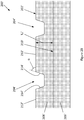
- Figure 3 illustrates a cross-sectional view through part of a thrust washer 300 according to the invention, viewed perpendicular to the oil distribution grooves 304.
- the thrust washer 300 comprises a profiled metallic substrate (e.g. a steel backing) 306 and a polymer layer 308 on an axial face 310 of the substrate.
- the polymer layer 308 has a substantially uniform thickness of 6 to 20 ⁇ m.
- the substrate 306 varies in thickness T s to provide a correspondingly profiled axial face 310 of the substrate.
- the polymer layer 308 has a substantially uniform thickness, and has an axial face 302 that is profiled in correspondence with the profiled axial face 310 of the substrate 306, to provide the oil distribution grooves 304 on the axial face 302 of the polymer.
- the oil distribution grooves 304 are provided between pad regions 312 in which the thrust washer 300 has a uniform thickness, and the grooves have a lesser thickness than the pad regions.
- the oil distribution grooves 304 each comprise a channel 304A and ramp regions 304B between the channel and the neighbouring pad regions 312. Although exaggerated for clarity, as per the first embodiment in Figure 2A , the ramp regions 304B have a low ramp slope ⁇ , corresponding to a gradient of approximately 1:300 to 1:100.
- the substrate is machined to provide the profiled axial substrate face before the polymer is deposited on the substrate as a layer of uniform thickness.
- the substrate may be conveniently machined before the substrate blank is formed from a sheet. Alternatively, the pre-formed substrate blank may be machined.
- the polymer in the invention may be deposited onto a pre-formed blank, after it has been stamped or otherwise formed from a sheet of substrate material.
- the polymer may be deposited onto an uncut sheet of substrate material, before the blank is formed.
- the polymer may be patterned when deposited (i.e. selective deposition rather than complete coverage of the substrate), for example by use of a pad printing process, a masked screen-printing process, or by a masked spraying process. Accordingly, the production of bi-material waste can be avoided. Further, even if the blanks were cut from a sheet of the metallic substrate, having polymer that extends beyond the blank, the metal-polymer bi-material waste would be less difficult to recycle than the manufacturing waste from a known bi-metal thrust washer.
- the metal substrate is a steel substrate.
- the profiled polymer layer is a composite of a plastics polymer matrix and particulate distributed throughout the matrix.
- the plastics polymer material is selected from the group consisting of: polyimide/amide resin, acrylate resin, epoxy resin, fluoropolymer and formaldehyde.
- the polymer may be a composite polyimide/amide based polymer, such as a composite having a matrix of a polyimide/amide plastics polymer material and having distributed throughout the matrix: from 5 to less than 25 %vol of a metal particulate (e.g.
- the metal powder and/or metal flakes from 1 to 20 %vol of a fluoropolymer, the balance being the polyimide/amide resin apart from incidental impurities.
- the polymer composite may be 12.5 %vol Al, 5.7 %vol PTFE particulate, 4.8 %vol silane, ⁇ 0.1 %vol other components, and balance (approximately 77 %vol) polyimide/amide.
Description
- The present invention relates to thrust washers having an axial face provided with oil distribution grooves, in particular thrust washers for use in automotive engines, transmission, pump and compressor systems.
- In internal combustion engines, the bearing assemblies typically each comprise a pair of half-bearings retaining a crankshaft that is rotatable about an axis. At least one half-bearing is a flange half-bearing that comprises a hollow generally semi-cylindrical bearing shell provided with a generally semi-annular thrust washer extending outwardly (radially) at each axial end. In some flange half-bearings, a single-piece construction of the bearing shell and thrust washers is used, whilst in other half-bearings, the bearing shell and the thrust washer are loosely mechanically engaged with clip-like features, and in a further type of half-bearing the thrust washers are permanently assembled onto the bearing shell by deformation of engagement features. In other bearing assemblies it is also known to use annular or circular thrust washer.
- Once the engine has started, lubricating oil is provided between the axial journal parts of the crankshaft and the bearing shells, and between the thrust washers and the counterfaces of associated webs of the crankshaft that extend perpendicular to the rotational axis of the crankshaft. However, when the engine starts, the oil pressure is low and may provide inadequate lubrication if the shaft contacts the bearing shell or a thrust washer. Further, even when the oil is supplied at normal operating pressures, axial forces on the shaft (e.g. when a gear change is performed, or due to the design of some automatic gearboxes) may cause the shaft to contact the thrust washer. Accordingly, the thrust washer and bearing shell are provided with running surfaces that can withstand such occasional contacts. Known bi-metal thrust washers comprise a steel backing (substrate) provided with an aluminium-tin (or copper-based alloy) running layer on an axial face of the substrate, with oil distribution grooves being provided either by machining a profile into the running layer, or by an embossing operation that provides a profile by causing deformation of the aluminium-tin running layer.
- Fuel-saving operating schemes have become popular for automotive engines, which increase the frequency with which the engine is started. Under a "stop-start" operating scheme, stopping and restarting vehicle movement also leads to the engine being stopping and being restarted. Under a "hybrid" operating scheme, the engine is turned off when the vehicle can be powered by an alternative power source, commonly being electrically powered. The greater frequency with which the engine is started under such operating schemes places an increased demand upon the performance of the thrust washers and bearing shells by increasing the frequency with which the counterfaces of the associated web and journals of the crankshaft respectively contact the thrust washers and bearing shells, and cause correspondingly increased wear of the running surfaces.
- Oil distribution grooves extend outwardly across the axial running face, e.g. radially from the inner edge to the outer edge. The grooves may comprise a deep channel with a gently sloping ramp on each side, between the channel and pad regions. The ramp region provides a tapered clearance between the thrust washer and the counterface of the crankshaft web, in use, assisting to draw lubricating oil out of the grooves across the axial face of the thrust washer, and providing a hydrodynamic wedge of lubrication oil to assist in maintaining separation of the thrust washer and the counterface of the web. Known oil distribution grooves are machined (e.g. milled) into the running layer, or formed by an embossing process.
- Known bi-metal washers are manufactured by stamping blanks from a bi-metal sheet, such that the manufacturing process produces bi-metal waste. Similarly, such washers produce further bi-metal waste at the end-of-life. However, such bi-metal waste, is difficult to recycle, due to the difficulty in separating the metals (i.e. separating the steel backing from the running layer).
- From
US 2006/288579 is a known thrust bearing which comprises a metal substrate layer and a polymer layer, wherein in the polymer layer a plurality of hydrodynamic pumping grooves are formed. - A first aspect of the invention provides a thrust washer comprising
- a metallic substrate layer having an axial substrate face,
- a polymer layer on the axial substrate face and having an axial polymer face opposed to the axial substrate face,
- A second aspect of the invention provides a flange bearing comprising a bearing shell and a thrust washer according to the first aspect. The flange bearing (i.e. one or two thrust washers and a bearing shell) may be: detachably, loosely clipped together; assembled to be inseparably physically engaged; or, comprise a single-part construction.
- A third aspect of the invention provides a method, not part of the invention, of forming a thrust washer comprising
- a metallic substrate layer having an axial substrate face,
- a polymer layer on the axial substrate face and having an axial polymer face opposed to the axial substrate face,
- depositing the polymer layer onto the metallic substrate layer and then
- machining the axial polymer face,
or - machining the axial substrate face and then
- depositing the polymer layer onto the machined substrate layer.
- Advantageously, the polymer layer may be more resilient against wear, fatigue and seizure than the aluminium-tin running layer of known bi-metal thrust washers.
- Advantageously, at the end-of-life, disposal of a metal and polymer bi-material thrust washer may be less difficult than that of known bi-metal thrust washers. Further, the manufacturing costs to form the profiled face of the polymer layer is less than to form a profiled face in the face of the aluminium-tin running layer of a known bi-metal thrust washer.
- The polymer layer may be the machined layer, which is not part of the invention. In the case that the polymer layer is the machined layer, the polymer layer may have a maximal thickness (i.e. in the pad regions) of 20 to 100µm. Advantageously, in the case that the polymer is machined to form the oil distribution groove, the polymer material may be machined more quickly than an aluminium-tin running layer in a known bi-metal thrust washer. Further, machining the polymer layer is less wearing on the tool-bit (e.g. cutting tool) used for the machining process than machining the metallic/metallic alloy (e.g. aluminium-tin or copper-alloy based) running layer of known bi-metal thrust washers, reducing manufacturing costs. Yet further, using machined polymer may enable the manufacture of a running layer with a smoother surface finish than for a known machined metal/metal alloy running layer, providing correspondingly improved hydrodynamic performance.
- Wear resistance of the polymer running layer may be greater than an aluminium-tin running layer, in particular in the case that the polymer layer comprises metallic particulate dispersed throughout the polymer. Further, the polymer layer may provide a lower coefficient of friction and greater compatibility than an aluminium-tin running layer, particularly in the case that the polymer layer comprises solid lubricant particulate dispersed throughout the polymer.
- The oil distribution groove may extend only part way through the polymer layer.
- The substrate layer is the machined layer. By the use of a polymer running layer, it is possible to provide the machining in the substrate layer (in contrast, in the known bi-metal thrust washer, a machined substrate would not be suitable for the application of an aluminium-tin running layer by a roll-bonding process). In the case that the substrate layer is the machined layer, the polymer layer may have a substantially uniform thickness of 6 to 20µm which follows the contours of the profiled face of the substrate layer onto which it is deposited, and preferably has a thickness of 6 to 12µm. Advantageously, machining the substrate layer enables the use of a thin polymer layer, with a corresponding cost saving for materials, which may also have an increased fatigue resistance compared with a thicker polymer layer. Further, machining the substrate layer avoids the risk of generating bi-material swarf from machining the running layer of known bi-metallic running layers, and so simplifies waste disposal. Yet further, machining the substrate layer enables use of a polymer layer that is not machined, thereby avoiding the risk of potential flaws in the edges of the polymer machining (referred to as a "feathered edge").
- The thrust washer may be generally semi-annular, annular or circular.
- The oil distribution groove comprises a channel and a ramp region. The channel region is the most deeply recessed part of the groove, and the ramp region has a low ramp slope. The ramp region has a ramp slope in which the increase in thickness of the machined layer is less than 25µm per 1mm across the axial face, perpendicular to the oil distribution groove.
- The oil distribution groove may comprise a channel between a first ramp region and a second ramp region. The first and second ramp regions may have different ramp slopes. Advantageously, the use of different ramp slopes may optimise the thrust washer for a particular direction of crankshaft rotation. The oil distribution groove may comprise the channel and one ramp region, the channel being bounded by an abrupt edge on the other side from the ramp region. Alternatively, the oil distribution groove may comprise a channel region between abrupt edges of the profiled polymer layer.
- The oil distribution groove may be provided between pad regions in which the thrust washer has a uniform thickness.
- The thrust washer may be provided with 1 to 10 oil distribution grooves. A thrust washer having an inner edge with a diameter of less than 70mm may have a 1 to 7 oil distribution grooves. A thrust washer having a diameter more than 70 mm may have 1 to 10 oil distribution grooves.
- The polymer layer may be the machined layer, which is not part of the invention, and the method may comprise depositing the polymer layer onto the metallic substrate layer, and then machining the axial polymer face.
- The substrate layer is the machined layer, and the method may comprise machining the axial substrate face, and then depositing the polymer layer onto the machined substrate layer.
- The method may comprise forming a substrate blank from a sheet of substrate material, and depositing the polymer onto the pre-formed substrate blank.
- The method may comprise depositing the polymer onto a sheet of substrate material, and forming polymer-coated substrate blanks from the sheet of substrate material.
- The method may comprise selectively depositing the polymer onto the sheet of substrate material.
- The method may comprise depositing the polymer by a process selected from the group consisting of: a pad printing process; a masked screen-printing process; or, by a masked spraying process.
- The method may comprise curing the polymer layer.
- The profiled polymer layer may be a plastics polymer material selected from the group consisting of: polyimide/amide resin, acrylate resin, epoxy resin, fluoropolymer (e.g. PTFE) and formaldehyde. The profiled polymer layer may comprise a composite of a plastics polymer matrix with particulate dispersed throughout the matrix. The particulate may be hard particulate (e.g. ceramic powder, silica, and metal powder such as aluminium flakes) and/or soft particulate (e.g. MoS2 and graphite, and fluoropolymer such as PTFE). The polymer may comprise a matrix of a polyimide/amide plastics polymer material and having distributed throughout the matrix: from 5 to less than 25 %vol of a metal particulate (e.g. metal powder and/or metal flakes); from 1 to 20 %vol of a fluoropolymer, the balance being the polyimide/amide resin apart from incidental impurities.
- Embodiments of the invention are further described hereinafter with reference to the accompanying drawings, in which:
-
Figures 1A and 1B show perspective views of thrust washers according to the present invention; and -
Figure 2A shows a cross-sectional view of a thrust washer according to a first example not part of the present invention, formed by a first manufacturing method; -
Figure 2B shows a cross-sectional view of a thrust washer according to a second example not part of the present invention, formed by a first manufacturing method; and -
Figure 3 shows a cross-sectional view of a thrust washer according to the present invention. - In the described embodiments, like features have been identified with like numerals, albeit in some cases having one or more of: increments of integer multiples of 100; and, typographical marks (e.g. primes). For example, in different figures, 100, 100', 200, 200' and 300 have been used to indicate a thrust washer.
-
Figure 1A illustrates athrust washer 100 that has a substantially semi-annular shape (e.g. it is generally semi-annular in shape, and may have projecting hooks and tabs, for engagement with other parts of the bearing assembly). An axial face 102 (i.e. a face perpendicular to the axis of rotation of a shaft received into a bearing assembly comprising the thrust washer) of thethrust washer 100 has paralleloil distribution grooves 104 running between the inner and outer edges of the thrust washer. In use, lubricating oil is pumped into the bearing clearance between a bearing shell and rotating shaft, and leaks out into the further clearance between the thrust washer and the rotating counterfaces of the crankshaft webs. The provision of theoil distribution grooves 104 in theaxial face 102 of thethrust washer 100 enhances the pressure and quality of the oil film between the thrust washer and the shaft. -
Figure 1B illustrates an alternative arrangement of oil distribution grooves 104' on the axial face 102' of a further thrust washer 100', in which the oil distribution grooves are aligned radially on the axial face. -
Figure 2A illustrates a cross-sectional view through part of athrust washer 200 according to a first example not part of the invention, viewed perpendicular to length of theoil distribution grooves 204. Thethrust washer 200 comprises a metallic substrate (e.g. a steel backing) 206 and a profiledpolymer layer 208 on anaxial face 210 of the substrate. - The
substrate 206 has a uniform thickness, and theoil distribution grooves 204 are provided in the axial face of the polymer 202 (axial polymer face, also the axial face of thrust washer) by the variation in thickness TP of thepolymer layer 208 across theaxial face 210 of the substrate (axial substrate face). Theoil distribution grooves 204 are provided betweenpad regions 212 in which thethrust washer 200 has a uniform thickness, and have a lesser thickness than the pad regions. Thepolymer layer 208 has a maximal thickness (in the pad regions) of 20 to 100µm. Theoil distribution grooves 204 each comprise achannel 204A andramp regions 204B between the channel and the neighbouringpad regions 212. Although exaggerated for clarity inFigure 2A , the channel is the deepest part of the groove, and theramp regions 204B have a low ramp slope θ, e.g. a gradient of approximately 1:300 to 1:100, e.g. 1:200, corresponding to approximately 1/3°. The ramp region provides a tapered clearance between thethrust washer 200 and the counterface of a crankshaft, in use, which provides a hydrodynamic wedge of lubrication oil to assist in maintaining separation of the thrust washer and counterface. - During manufacturing, the polymer is deposited on the substrate as a layer of approximately uniform thickness, and fully cured, before the variable thickness profile is formed by a machining process. The polymer may be deposited onto a pre-formed substrate blank, after it has been stamped or otherwise formed from a sheet of substrate material. Alternatively, the polymer may be deposited onto an uncut sheet of substrate material, before the coated substrate blank is formed. In the latter case, the polymer may be patterned when deposited (i.e. selective deposition rather than complete coverage of the substrate), for example by use of a pad printing process, a masked screen-printing process, or by a masked spraying process. Accordingly, the production of bi-material waste can be avoided. Further, even if the blanks were cut from a sheet of the metallic substrate, having polymer that extends beyond the blank, onto the substrate waste, the metal-polymer bi-material waste would be less difficult to recycle than the manufacturing waste from a known bi-metal thrust washer. Similarly, at the end-of-life, the metal-polymer thrust washer is less difficult to recycle than a known bi-metal thrust washer.
- In
Figures 2A each oil distribution groove is substantially symmetric, having a channel formed between a pair of ramp regions having equal ramp slopes. However, the thrust washer may be optimised for rotation of the shaft in a particular direction, in which case the ramp regions on opposite sides of each oil distribution groove may have different ramp slopes (i.e. the oil distribution grooves may have asymmetric cross-sections), or one of the ramp regions may be omitted, such that the oil distribution grooves have only one ramp region, with a relatively abrupt edge to the polymer (e.g. an edge that is perpendicular to the plane of the thrust washer, or at more than 45° to the plane of the thrust washer) on the other side of the channel. -
Figure 2B illustrates a further example not part of the invention, which the thrust washer 200' differs from thethrust washer 200 ofFigure 2A by having oil distribution grooves without ramp regions, in which the grooves each comprise channels 204' that are defined by abrupt edges 214' of the polymer 208'. The channel 204' may be trapezoidal (or have a rounded-shape) in cross-sectional shape, and the abrupt edges 214' form an angle α of 65° with the plane of the thrust washer, in the illustrated example. -
Figure 3 illustrates a cross-sectional view through part of athrust washer 300 according to the invention, viewed perpendicular to theoil distribution grooves 304. Thethrust washer 300 comprises a profiled metallic substrate (e.g. a steel backing) 306 and apolymer layer 308 on anaxial face 310 of the substrate. Thepolymer layer 308 has a substantially uniform thickness of 6 to 20µm. - The
substrate 306 varies in thickness Ts to provide a correspondingly profiledaxial face 310 of the substrate. Thepolymer layer 308 has a substantially uniform thickness, and has anaxial face 302 that is profiled in correspondence with the profiledaxial face 310 of thesubstrate 306, to provide theoil distribution grooves 304 on theaxial face 302 of the polymer. Theoil distribution grooves 304 are provided betweenpad regions 312 in which thethrust washer 300 has a uniform thickness, and the grooves have a lesser thickness than the pad regions. Theoil distribution grooves 304 each comprise achannel 304A andramp regions 304B between the channel and the neighbouringpad regions 312. Although exaggerated for clarity, as per the first embodiment inFigure 2A , theramp regions 304B have a low ramp slope θ, corresponding to a gradient of approximately 1:300 to 1:100. - During manufacturing, the substrate is machined to provide the profiled axial substrate face before the polymer is deposited on the substrate as a layer of uniform thickness. The substrate may be conveniently machined before the substrate blank is formed from a sheet. Alternatively, the pre-formed substrate blank may be machined.
- As with the first example, the polymer in the invention may be deposited onto a pre-formed blank, after it has been stamped or otherwise formed from a sheet of substrate material. Alternatively, the polymer may be deposited onto an uncut sheet of substrate material, before the blank is formed. In the latter case, the polymer may be patterned when deposited (i.e. selective deposition rather than complete coverage of the substrate), for example by use of a pad printing process, a masked screen-printing process, or by a masked spraying process. Accordingly, the production of bi-material waste can be avoided. Further, even if the blanks were cut from a sheet of the metallic substrate, having polymer that extends beyond the blank, the metal-polymer bi-material waste would be less difficult to recycle than the manufacturing waste from a known bi-metal thrust washer.
- In the illustrated examples and in the invention, The metal substrate is a steel substrate. The profiled polymer layer is a composite of a plastics polymer matrix and particulate distributed throughout the matrix. The plastics polymer material is selected from the group consisting of: polyimide/amide resin, acrylate resin, epoxy resin, fluoropolymer and formaldehyde. In particular, the polymer may be a composite polyimide/amide based polymer, such as a composite having a matrix of a polyimide/amide plastics polymer material and having distributed throughout the matrix: from 5 to less than 25 %vol of a metal particulate (e.g. metal powder and/or metal flakes); from 1 to 20 %vol of a fluoropolymer, the balance being the polyimide/amide resin apart from incidental impurities. Further, the polymer composite may be 12.5 %vol Al, 5.7 %vol PTFE particulate, 4.8 %vol silane, <0.1 %vol other components, and balance (approximately 77 %vol) polyimide/amide.
- Although illustrated in
Figures 1A and 1B in relation to a generally semi-annular thrust washer, the present invention equally applies to annular or circular thrust washers. - The figures provided herein are schematic and not to scale.
- Throughout the description and claims of this specification, the words "comprise" and "contain" and variations of them mean "including but not limited to", and they are not intended to (and do not) exclude other moieties, additives, components, integers or steps. Throughout the description and claims of this specification, the singular encompasses the plural unless the context otherwise requires. In particular, where the indefinite article is used, the specification is to be understood as contemplating plurality as well as singularity, unless the context requires otherwise.
- Features, integers, characteristics, compounds, chemical moieties or groups described in conjunction with a particular aspect, embodiment or example of the invention are to be understood to be applicable to any other aspect, embodiment or example described herein unless incompatible therewith. All of the features disclosed in this specification (including any accompanying claims, abstract and drawings), and/or all of the steps of any method or process so disclosed, may be combined in any combination, except combinations where at least some of such features and/or steps are mutually exclusive. The invention is not restricted to the details of the foregoing embodiment. The invention extends to any novel one, or any novel combination, of the features disclosed in this specification (including any accompanying claims, abstract and drawings).
- The reader's attention is directed to all papers and documents which are filed concurrently with or previous to this specification in connection with this application and which are open to public inspection with this specification, and the contents of all such papers and documents are incorporated herein by reference.
the method comprising either
Claims (4)
- A thrust washer comprising
a metallic substrate layer (306) having an axial substrate face (310),
a polymer layer (308) on the axial substrate face (310) and having an axial polymer face (302) opposed to the axial substrate face(310),
wherein the axial polymer face (302) is profiled and has at least one oil distribution groove (304), and
the substrate layer (306) is a machined layer having a thickness Ts that varies in correspondence with the at least one oil distribution groove (304),
wherein the oil distribution groove (304) comprises a channel (304A) and a ramp region (304B), wherein the ramp region (304B) has a ramp slope θ in which the increase in thickness
of the machined layer is less than 25µm per 1mm across the axial face, perpendicular to the oil distribution groove (304). - A thrust washer according to claim 1, wherein the oil distribution groove (304) comprises a channel (304A) between a first ramp region (304B) and a second ramp region (304B).
- A thrust washer according to any preceding claim, wherein the oil distribution groove (304) is provided between pad regions (312) in which the thrust washer (300) has a uniform thickness.
- A flange bearing comprising a bearing shell and a thrust washer (300) according to any preceding claim.
Applications Claiming Priority (2)
| Application Number | Priority Date | Filing Date | Title |
|---|---|---|---|
| GB1222653.6A GB2508915A (en) | 2012-12-14 | 2012-12-14 | A thrust washer for a sliding bearing |
| PCT/GB2013/053213 WO2014091207A1 (en) | 2012-12-14 | 2013-12-05 | Thrust washer |
Publications (2)
| Publication Number | Publication Date |
|---|---|
| EP2932113A1 EP2932113A1 (en) | 2015-10-21 |
| EP2932113B1 true EP2932113B1 (en) | 2020-06-17 |
Family
ID=47630803
Family Applications (1)
| Application Number | Title | Priority Date | Filing Date |
|---|---|---|---|
| EP13805481.2A Active EP2932113B1 (en) | 2012-12-14 | 2013-12-05 | Thrust washer |
Country Status (8)
| Country | Link |
|---|---|
| US (1) | US9746023B2 (en) |
| EP (1) | EP2932113B1 (en) |
| JP (1) | JP6625882B2 (en) |
| KR (2) | KR20200076763A (en) |
| CN (1) | CN104937290B (en) |
| BR (1) | BR112015013616A2 (en) |
| GB (1) | GB2508915A (en) |
| WO (1) | WO2014091207A1 (en) |
Families Citing this family (12)
| Publication number | Priority date | Publication date | Assignee | Title |
|---|---|---|---|---|
| JP6228558B2 (en) * | 2015-03-10 | 2017-11-08 | 大豊工業株式会社 | Thrust plain bearing |
| BR102015005671B1 (en) * | 2015-03-13 | 2022-05-17 | Mahle Metal Leve S/A | thrust washer |
| EP3315805B1 (en) * | 2015-06-24 | 2020-10-28 | Taiho Kogyo Co., Ltd | Washer and method of manufacturing washers |
| WO2017170544A1 (en) * | 2016-03-29 | 2017-10-05 | 大豊工業株式会社 | Washer |
| BR102016020154A2 (en) * | 2016-08-31 | 2018-03-20 | Mahle Metal Leve S.A. | BACK WASHER |
| JP6576976B2 (en) * | 2017-06-12 | 2019-09-18 | 大同メタル工業株式会社 | Half thrust bearing |
| JP6571130B2 (en) * | 2017-06-12 | 2019-09-04 | 大同メタル工業株式会社 | Half thrust bearing |
| JP6574826B2 (en) * | 2017-11-10 | 2019-09-11 | 大同メタル工業株式会社 | Half thrust bearing, thrust bearing, bearing device and internal combustion engine |
| JP6767349B2 (en) * | 2017-11-30 | 2020-10-14 | 大豊工業株式会社 | Thrust washer |
| JP2019108923A (en) * | 2017-12-18 | 2019-07-04 | トヨタ自動車株式会社 | Thrust bearing and bearing device |
| DE102019107146B4 (en) | 2019-01-30 | 2021-02-25 | Jenoptik Optical Systems Gmbh | Athermal laser optics made of plastic |
| CN110500355B (en) * | 2019-08-28 | 2021-12-28 | 杭州尚拓金属制品有限公司 | Thrust washer |
Citations (14)
| Publication number | Priority date | Publication date | Assignee | Title |
|---|---|---|---|---|
| GB102722A (en) | 1915-12-14 | 1917-11-01 | Escher Wyss Maschf Ag | Improvements in Annular Footstep Bearings. |
| DE3041845A1 (en) | 1979-12-25 | 1981-07-02 | Taiho Kogyo Co., Ltd., Toyota, Aichi | AXIAL PRESSURE SLIDE BEARING |
| JPS59187110A (en) | 1983-04-06 | 1984-10-24 | Taiho Kogyo Co Ltd | Tapered land thrust bearing |
| JPS63158620U (en) | 1987-04-03 | 1988-10-18 | ||
| US20020094143A1 (en) | 2001-01-16 | 2002-07-18 | Federal-Mogul World Wide, Inc. | Flange bearing |
| EP1387097A1 (en) * | 2001-03-27 | 2004-02-04 | Nok Corporation | Thrust bearing |
| JP2004293684A (en) * | 2003-03-27 | 2004-10-21 | Nok Corp | Thrust bearing |
| US20060034556A1 (en) * | 2004-08-11 | 2006-02-16 | Federal-Mogul World Wide, Inc. | Thrust bearing assembly |
| AT501878B1 (en) | 2005-04-29 | 2008-05-15 | Miba Gleitlager Gmbh | BEARING ELEMENT |
| JP2008144864A (en) | 2006-12-11 | 2008-06-26 | Nok Corp | Thrust bearing |
| CN101749321A (en) | 2010-02-02 | 2010-06-23 | 常州市中瑞汽车配件有限公司 | Thrust bearing used for booster |
| EP1886033B1 (en) | 2005-06-01 | 2011-07-06 | Federal-Mogul Corporation | Thrust bearing |
| DE102011101334A1 (en) | 2011-05-12 | 2012-11-15 | Daimler Ag | Connecting rod for converting linear motion of piston of internal combustion engine of motor car into rotational motion of crankshaft of engine, has rod bearing whose axial bearing surface comprises form surfaces differing from chamfer |
| WO2013094351A1 (en) * | 2011-12-22 | 2013-06-27 | 大豊工業株式会社 | Sliding member and manufacturing method therefor |
Family Cites Families (33)
| Publication number | Priority date | Publication date | Assignee | Title |
|---|---|---|---|---|
| US2362667A (en) * | 1942-05-15 | 1944-11-14 | Westinghouse Electric & Mfg Co | Thrust bearing |
| US3597027A (en) * | 1969-02-28 | 1971-08-03 | Gen Motors Corp | Thrust bearing |
| JPS5945850B2 (en) * | 1979-07-13 | 1984-11-09 | 株式会社日立製作所 | thrust bearing |
| JPS58166120A (en) * | 1982-03-27 | 1983-10-01 | Taiho Kogyo Co Ltd | Tapered land thrust bearing device |
| GB2193267B (en) * | 1986-06-03 | 1989-12-20 | Ae Plc | Bearings |
| GB8613411D0 (en) * | 1986-06-03 | 1986-07-09 | Ae Plc | Bearings |
| JPS63158316A (en) * | 1986-12-19 | 1988-07-01 | Daido Metal Kogyo Kk | Thrust bearing |
| JPH0276925A (en) * | 1988-09-09 | 1990-03-16 | Nippon Seiko Kk | Anti-wear sliding member |
| IL97378A (en) * | 1990-03-08 | 1994-04-12 | Plastic Bearings & Housings Au | Bearing assemblies |
| US5192136A (en) * | 1991-12-19 | 1993-03-09 | Federal-Mogul Corporation | Crankshaft bearing having hydrodynamic thrust flanges |
| JP2509864B2 (en) * | 1993-03-18 | 1996-06-26 | エヌデーシー株式会社 | Method for producing multi-layer bearing material having oil sump on bearing surface |
| US6132094A (en) * | 1998-12-21 | 2000-10-17 | Fmc Corporation | Multiple groove thrust bearing |
| JP2000192961A (en) * | 1998-12-25 | 2000-07-11 | Oiles Ind Co Ltd | Plural-layer sliding member and manufacture therefor |
| JP4396791B2 (en) * | 2000-02-04 | 2010-01-13 | Nok株式会社 | Plastic thrust bearing manufacturing method |
| HU228100B1 (en) * | 2001-03-16 | 2012-10-29 | Taiho Kogyo Co Ltd | Sliding material |
| US20020181811A1 (en) * | 2001-06-05 | 2002-12-05 | Aguilar Scott Grover | Diverted flow thrust bearing |
| US20030128902A1 (en) * | 2002-01-10 | 2003-07-10 | Detroit Diesel Corporation | Snap together thrust and journal bearing assembly |
| JP2004052998A (en) * | 2002-05-28 | 2004-02-19 | Mitsubishi Materials Corp | Sliding member provided with dynamic pressure generating groove and manufacturing method therefor |
| JP4287098B2 (en) * | 2002-07-18 | 2009-07-01 | 日本電産サンキョー株式会社 | Bearing device and manufacturing method thereof |
| US20060083451A1 (en) | 2003-01-08 | 2006-04-20 | Kimio Kawagoe | Sliding bearing |
| US6921210B2 (en) * | 2003-04-11 | 2005-07-26 | Federal-Mogul World Wide, Inc. | Flange bearing |
| JP4515824B2 (en) * | 2004-05-27 | 2010-08-04 | Ntn株式会社 | High precision plain bearing |
| US7458158B2 (en) * | 2005-06-28 | 2008-12-02 | Federal-Mogul World Wide, Inc. | Method of making a sliding bearing |
| JP2007032669A (en) * | 2005-07-26 | 2007-02-08 | Nok Corp | Thrust bearing |
| KR100690930B1 (en) * | 2006-05-03 | 2007-03-09 | 한국기계연구원 | Method for preparing a high resolution pattern with a high aspect ratio and the pattern thickness required by using deep ablation |
| JP2008014454A (en) * | 2006-07-07 | 2008-01-24 | Daido Metal Co Ltd | Sliding bearing |
| JP2008261474A (en) * | 2007-03-19 | 2008-10-30 | Nok Corp | Thrust washer |
| DE102007044850B3 (en) * | 2007-09-13 | 2009-08-06 | Federal-Mogul Wiesbaden Gmbh | Thrust washer and radial-axial bearing with such |
| CN102124235B (en) * | 2008-05-20 | 2015-09-23 | 马勒金属制品有限公司 | Flange bearing and flange |
| JP2012047276A (en) * | 2010-08-27 | 2012-03-08 | Taiho Kogyo Co Ltd | Sliding bearing and method for manufacturing the same |
| JP5635352B2 (en) * | 2010-09-30 | 2014-12-03 | Ntn株式会社 | Compound plain bearing |
| DE102011083905A1 (en) | 2011-09-30 | 2013-04-04 | Ks Gleitlager Gmbh | Suspension strut bearing in a steerable vehicle wheel suspension |
| JP2014142019A (en) * | 2013-01-24 | 2014-08-07 | Taiho Kogyo Co Ltd | Thrust bearing |
-
2012
- 2012-12-14 GB GB1222653.6A patent/GB2508915A/en not_active Withdrawn
-
2013
- 2013-12-05 JP JP2015547137A patent/JP6625882B2/en not_active Expired - Fee Related
- 2013-12-05 US US14/652,104 patent/US9746023B2/en active Active
- 2013-12-05 KR KR1020207017789A patent/KR20200076763A/en not_active Application Discontinuation
- 2013-12-05 KR KR1020157015667A patent/KR20150132079A/en not_active Application Discontinuation
- 2013-12-05 CN CN201380063874.5A patent/CN104937290B/en not_active Expired - Fee Related
- 2013-12-05 WO PCT/GB2013/053213 patent/WO2014091207A1/en active Application Filing
- 2013-12-05 BR BR112015013616A patent/BR112015013616A2/en active Search and Examination
- 2013-12-05 EP EP13805481.2A patent/EP2932113B1/en active Active
Patent Citations (15)
| Publication number | Priority date | Publication date | Assignee | Title |
|---|---|---|---|---|
| GB102722A (en) | 1915-12-14 | 1917-11-01 | Escher Wyss Maschf Ag | Improvements in Annular Footstep Bearings. |
| DE3041845A1 (en) | 1979-12-25 | 1981-07-02 | Taiho Kogyo Co., Ltd., Toyota, Aichi | AXIAL PRESSURE SLIDE BEARING |
| JPS59187110A (en) | 1983-04-06 | 1984-10-24 | Taiho Kogyo Co Ltd | Tapered land thrust bearing |
| JPS63158620U (en) | 1987-04-03 | 1988-10-18 | ||
| US20020094143A1 (en) | 2001-01-16 | 2002-07-18 | Federal-Mogul World Wide, Inc. | Flange bearing |
| EP1387097A1 (en) * | 2001-03-27 | 2004-02-04 | Nok Corporation | Thrust bearing |
| JP2004293684A (en) * | 2003-03-27 | 2004-10-21 | Nok Corp | Thrust bearing |
| US20060034556A1 (en) * | 2004-08-11 | 2006-02-16 | Federal-Mogul World Wide, Inc. | Thrust bearing assembly |
| AT501878B1 (en) | 2005-04-29 | 2008-05-15 | Miba Gleitlager Gmbh | BEARING ELEMENT |
| EP1886033B1 (en) | 2005-06-01 | 2011-07-06 | Federal-Mogul Corporation | Thrust bearing |
| JP2008144864A (en) | 2006-12-11 | 2008-06-26 | Nok Corp | Thrust bearing |
| CN101749321A (en) | 2010-02-02 | 2010-06-23 | 常州市中瑞汽车配件有限公司 | Thrust bearing used for booster |
| DE102011101334A1 (en) | 2011-05-12 | 2012-11-15 | Daimler Ag | Connecting rod for converting linear motion of piston of internal combustion engine of motor car into rotational motion of crankshaft of engine, has rod bearing whose axial bearing surface comprises form surfaces differing from chamfer |
| WO2013094351A1 (en) * | 2011-12-22 | 2013-06-27 | 大豊工業株式会社 | Sliding member and manufacturing method therefor |
| EP2796736A1 (en) * | 2011-12-22 | 2014-10-29 | Taiho Kogyo Co., Ltd | Sliding member and manufacturing method therefor |
Also Published As
| Publication number | Publication date |
|---|---|
| JP2016500430A (en) | 2016-01-12 |
| BR112015013616A2 (en) | 2017-07-11 |
| CN104937290A (en) | 2015-09-23 |
| US9746023B2 (en) | 2017-08-29 |
| CN104937290B (en) | 2017-09-05 |
| WO2014091207A1 (en) | 2014-06-19 |
| JP6625882B2 (en) | 2019-12-25 |
| US20150323006A1 (en) | 2015-11-12 |
| KR20200076763A (en) | 2020-06-29 |
| EP2932113A1 (en) | 2015-10-21 |
| KR20150132079A (en) | 2015-11-25 |
| GB201222653D0 (en) | 2013-01-30 |
| GB2508915A (en) | 2014-06-18 |
Similar Documents
| Publication | Publication Date | Title |
|---|---|---|
| EP2932113B1 (en) | Thrust washer | |
| EP2932112B1 (en) | Thrust washer | |
| EP1584828B1 (en) | Sliding bearing | |
| WO2002077473A1 (en) | Thrust bearing | |
| EP2643604B1 (en) | Bearing with integrated seals | |
| US10228014B2 (en) | Internal combustion engine bearing and method of manufacturing internal combustion engine bearing | |
| US20020034349A1 (en) | Aluminum thrust washer | |
| EP2917598B1 (en) | Sliding bearing with bearing substrate and polymer in-fill | |
| WO2017090287A1 (en) | Half bearing | |
| GB2537857A (en) | Thrust washer comprising a polymer running layer having a textured surface | |
| US10962054B2 (en) | Half bearing | |
| JP2016223565A (en) | Sliding member for internal combustion engine | |
| CN110139991B (en) | Half bearing | |
| JP2007064429A (en) | Roller bearing | |
| BR112015012963B1 (en) | ANCHOR WASHER | |
| WO2023064861A1 (en) | Sliding material, bearing, and methods of making and using the same | |
| EP2547921B1 (en) | Half bearing | |
| JP5020009B2 (en) | Plain bearing |
Legal Events
| Date | Code | Title | Description |
|---|---|---|---|
| PUAI | Public reference made under article 153(3) epc to a published international application that has entered the european phase |
Free format text: ORIGINAL CODE: 0009012 |
|
| 17P | Request for examination filed |
Effective date: 20150521 |
|
| AK | Designated contracting states |
Kind code of ref document: A1 Designated state(s): AL AT BE BG CH CY CZ DE DK EE ES FI FR GB GR HR HU IE IS IT LI LT LU LV MC MK MT NL NO PL PT RO RS SE SI SK SM TR |
|
| AX | Request for extension of the european patent |
Extension state: BA ME |
|
| DAX | Request for extension of the european patent (deleted) | ||
| STAA | Information on the status of an ep patent application or granted ep patent |
Free format text: STATUS: EXAMINATION IS IN PROGRESS |
|
| 17Q | First examination report despatched |
Effective date: 20180206 |
|
| GRAP | Despatch of communication of intention to grant a patent |
Free format text: ORIGINAL CODE: EPIDOSNIGR1 |
|
| STAA | Information on the status of an ep patent application or granted ep patent |
Free format text: STATUS: GRANT OF PATENT IS INTENDED |
|
| INTG | Intention to grant announced |
Effective date: 20200115 |
|
| GRAS | Grant fee paid |
Free format text: ORIGINAL CODE: EPIDOSNIGR3 |
|
| GRAA | (expected) grant |
Free format text: ORIGINAL CODE: 0009210 |
|
| STAA | Information on the status of an ep patent application or granted ep patent |
Free format text: STATUS: THE PATENT HAS BEEN GRANTED |
|
| AK | Designated contracting states |
Kind code of ref document: B1 Designated state(s): AL AT BE BG CH CY CZ DE DK EE ES FI FR GB GR HR HU IE IS IT LI LT LU LV MC MK MT NL NO PL PT RO RS SE SI SK SM TR |
|
| REG | Reference to a national code |
Ref country code: GB Ref legal event code: FG4D |
|
| REG | Reference to a national code |
Ref country code: CH Ref legal event code: EP |
|
| REG | Reference to a national code |
Ref country code: IE Ref legal event code: FG4D |
|
| REG | Reference to a national code |
Ref country code: DE Ref legal event code: R096 Ref document number: 602013069974 Country of ref document: DE |
|
| REG | Reference to a national code |
Ref country code: AT Ref legal event code: REF Ref document number: 1281658 Country of ref document: AT Kind code of ref document: T Effective date: 20200715 |
|
| PG25 | Lapsed in a contracting state [announced via postgrant information from national office to epo] |
Ref country code: GR Free format text: LAPSE BECAUSE OF FAILURE TO SUBMIT A TRANSLATION OF THE DESCRIPTION OR TO PAY THE FEE WITHIN THE PRESCRIBED TIME-LIMIT Effective date: 20200918 Ref country code: NO Free format text: LAPSE BECAUSE OF FAILURE TO SUBMIT A TRANSLATION OF THE DESCRIPTION OR TO PAY THE FEE WITHIN THE PRESCRIBED TIME-LIMIT Effective date: 20200917 Ref country code: FI Free format text: LAPSE BECAUSE OF FAILURE TO SUBMIT A TRANSLATION OF THE DESCRIPTION OR TO PAY THE FEE WITHIN THE PRESCRIBED TIME-LIMIT Effective date: 20200617 Ref country code: LT Free format text: LAPSE BECAUSE OF FAILURE TO SUBMIT A TRANSLATION OF THE DESCRIPTION OR TO PAY THE FEE WITHIN THE PRESCRIBED TIME-LIMIT Effective date: 20200617 Ref country code: SE Free format text: LAPSE BECAUSE OF FAILURE TO SUBMIT A TRANSLATION OF THE DESCRIPTION OR TO PAY THE FEE WITHIN THE PRESCRIBED TIME-LIMIT Effective date: 20200617 |
|
| REG | Reference to a national code |
Ref country code: LT Ref legal event code: MG4D |
|
| REG | Reference to a national code |
Ref country code: NL Ref legal event code: MP Effective date: 20200617 |
|
| PG25 | Lapsed in a contracting state [announced via postgrant information from national office to epo] |
Ref country code: LV Free format text: LAPSE BECAUSE OF FAILURE TO SUBMIT A TRANSLATION OF THE DESCRIPTION OR TO PAY THE FEE WITHIN THE PRESCRIBED TIME-LIMIT Effective date: 20200617 Ref country code: HR Free format text: LAPSE BECAUSE OF FAILURE TO SUBMIT A TRANSLATION OF THE DESCRIPTION OR TO PAY THE FEE WITHIN THE PRESCRIBED TIME-LIMIT Effective date: 20200617 Ref country code: BG Free format text: LAPSE BECAUSE OF FAILURE TO SUBMIT A TRANSLATION OF THE DESCRIPTION OR TO PAY THE FEE WITHIN THE PRESCRIBED TIME-LIMIT Effective date: 20200917 Ref country code: RS Free format text: LAPSE BECAUSE OF FAILURE TO SUBMIT A TRANSLATION OF THE DESCRIPTION OR TO PAY THE FEE WITHIN THE PRESCRIBED TIME-LIMIT Effective date: 20200617 |
|
| REG | Reference to a national code |
Ref country code: AT Ref legal event code: MK05 Ref document number: 1281658 Country of ref document: AT Kind code of ref document: T Effective date: 20200617 |
|
| PG25 | Lapsed in a contracting state [announced via postgrant information from national office to epo] |
Ref country code: AL Free format text: LAPSE BECAUSE OF FAILURE TO SUBMIT A TRANSLATION OF THE DESCRIPTION OR TO PAY THE FEE WITHIN THE PRESCRIBED TIME-LIMIT Effective date: 20200617 Ref country code: NL Free format text: LAPSE BECAUSE OF FAILURE TO SUBMIT A TRANSLATION OF THE DESCRIPTION OR TO PAY THE FEE WITHIN THE PRESCRIBED TIME-LIMIT Effective date: 20200617 |
|
| PG25 | Lapsed in a contracting state [announced via postgrant information from national office to epo] |
Ref country code: PT Free format text: LAPSE BECAUSE OF FAILURE TO SUBMIT A TRANSLATION OF THE DESCRIPTION OR TO PAY THE FEE WITHIN THE PRESCRIBED TIME-LIMIT Effective date: 20201019 Ref country code: EE Free format text: LAPSE BECAUSE OF FAILURE TO SUBMIT A TRANSLATION OF THE DESCRIPTION OR TO PAY THE FEE WITHIN THE PRESCRIBED TIME-LIMIT Effective date: 20200617 Ref country code: AT Free format text: LAPSE BECAUSE OF FAILURE TO SUBMIT A TRANSLATION OF THE DESCRIPTION OR TO PAY THE FEE WITHIN THE PRESCRIBED TIME-LIMIT Effective date: 20200617 Ref country code: RO Free format text: LAPSE BECAUSE OF FAILURE TO SUBMIT A TRANSLATION OF THE DESCRIPTION OR TO PAY THE FEE WITHIN THE PRESCRIBED TIME-LIMIT Effective date: 20200617 Ref country code: ES Free format text: LAPSE BECAUSE OF FAILURE TO SUBMIT A TRANSLATION OF THE DESCRIPTION OR TO PAY THE FEE WITHIN THE PRESCRIBED TIME-LIMIT Effective date: 20200617 Ref country code: SM Free format text: LAPSE BECAUSE OF FAILURE TO SUBMIT A TRANSLATION OF THE DESCRIPTION OR TO PAY THE FEE WITHIN THE PRESCRIBED TIME-LIMIT Effective date: 20200617 Ref country code: IT Free format text: LAPSE BECAUSE OF FAILURE TO SUBMIT A TRANSLATION OF THE DESCRIPTION OR TO PAY THE FEE WITHIN THE PRESCRIBED TIME-LIMIT Effective date: 20200617 Ref country code: CZ Free format text: LAPSE BECAUSE OF FAILURE TO SUBMIT A TRANSLATION OF THE DESCRIPTION OR TO PAY THE FEE WITHIN THE PRESCRIBED TIME-LIMIT Effective date: 20200617 |
|
| PG25 | Lapsed in a contracting state [announced via postgrant information from national office to epo] |
Ref country code: IS Free format text: LAPSE BECAUSE OF FAILURE TO SUBMIT A TRANSLATION OF THE DESCRIPTION OR TO PAY THE FEE WITHIN THE PRESCRIBED TIME-LIMIT Effective date: 20201017 Ref country code: PL Free format text: LAPSE BECAUSE OF FAILURE TO SUBMIT A TRANSLATION OF THE DESCRIPTION OR TO PAY THE FEE WITHIN THE PRESCRIBED TIME-LIMIT Effective date: 20200617 Ref country code: SK Free format text: LAPSE BECAUSE OF FAILURE TO SUBMIT A TRANSLATION OF THE DESCRIPTION OR TO PAY THE FEE WITHIN THE PRESCRIBED TIME-LIMIT Effective date: 20200617 |
|
| REG | Reference to a national code |
Ref country code: DE Ref legal event code: R026 Ref document number: 602013069974 Country of ref document: DE |
|
| PLBI | Opposition filed |
Free format text: ORIGINAL CODE: 0009260 |
|
| PLAX | Notice of opposition and request to file observation + time limit sent |
Free format text: ORIGINAL CODE: EPIDOSNOBS2 |
|
| 26 | Opposition filed |
Opponent name: MIBA GLEITLAGE AUSTRIA GMBH Effective date: 20210317 |
|
| PG25 | Lapsed in a contracting state [announced via postgrant information from national office to epo] |
Ref country code: DK Free format text: LAPSE BECAUSE OF FAILURE TO SUBMIT A TRANSLATION OF THE DESCRIPTION OR TO PAY THE FEE WITHIN THE PRESCRIBED TIME-LIMIT Effective date: 20200617 |
|
| PG25 | Lapsed in a contracting state [announced via postgrant information from national office to epo] |
Ref country code: SI Free format text: LAPSE BECAUSE OF FAILURE TO SUBMIT A TRANSLATION OF THE DESCRIPTION OR TO PAY THE FEE WITHIN THE PRESCRIBED TIME-LIMIT Effective date: 20200617 |
|
| REG | Reference to a national code |
Ref country code: CH Ref legal event code: PL |
|
| PLBB | Reply of patent proprietor to notice(s) of opposition received |
Free format text: ORIGINAL CODE: EPIDOSNOBS3 |
|
| GBPC | Gb: european patent ceased through non-payment of renewal fee |
Effective date: 20201205 |
|
| PG25 | Lapsed in a contracting state [announced via postgrant information from national office to epo] |
Ref country code: MC Free format text: LAPSE BECAUSE OF FAILURE TO SUBMIT A TRANSLATION OF THE DESCRIPTION OR TO PAY THE FEE WITHIN THE PRESCRIBED TIME-LIMIT Effective date: 20200617 |
|
| REG | Reference to a national code |
Ref country code: BE Ref legal event code: MM Effective date: 20201231 |
|
| PG25 | Lapsed in a contracting state [announced via postgrant information from national office to epo] |
Ref country code: IE Free format text: LAPSE BECAUSE OF NON-PAYMENT OF DUE FEES Effective date: 20201205 Ref country code: LU Free format text: LAPSE BECAUSE OF NON-PAYMENT OF DUE FEES Effective date: 20201205 Ref country code: FR Free format text: LAPSE BECAUSE OF NON-PAYMENT OF DUE FEES Effective date: 20201231 |
|
| PG25 | Lapsed in a contracting state [announced via postgrant information from national office to epo] |
Ref country code: LI Free format text: LAPSE BECAUSE OF NON-PAYMENT OF DUE FEES Effective date: 20201231 Ref country code: GB Free format text: LAPSE BECAUSE OF NON-PAYMENT OF DUE FEES Effective date: 20201205 Ref country code: CH Free format text: LAPSE BECAUSE OF NON-PAYMENT OF DUE FEES Effective date: 20201231 |
|
| PLAB | Opposition data, opponent's data or that of the opponent's representative modified |
Free format text: ORIGINAL CODE: 0009299OPPO |
|
| R26 | Opposition filed (corrected) |
Opponent name: MIBA GLEITLAGE AUSTRIA GMBH Effective date: 20210317 |
|
| PG25 | Lapsed in a contracting state [announced via postgrant information from national office to epo] |
Ref country code: IS Free format text: LAPSE BECAUSE OF FAILURE TO SUBMIT A TRANSLATION OF THE DESCRIPTION OR TO PAY THE FEE WITHIN THE PRESCRIBED TIME-LIMIT Effective date: 20201017 Ref country code: TR Free format text: LAPSE BECAUSE OF FAILURE TO SUBMIT A TRANSLATION OF THE DESCRIPTION OR TO PAY THE FEE WITHIN THE PRESCRIBED TIME-LIMIT Effective date: 20200617 Ref country code: MT Free format text: LAPSE BECAUSE OF FAILURE TO SUBMIT A TRANSLATION OF THE DESCRIPTION OR TO PAY THE FEE WITHIN THE PRESCRIBED TIME-LIMIT Effective date: 20200617 Ref country code: CY Free format text: LAPSE BECAUSE OF FAILURE TO SUBMIT A TRANSLATION OF THE DESCRIPTION OR TO PAY THE FEE WITHIN THE PRESCRIBED TIME-LIMIT Effective date: 20200617 |
|
| PG25 | Lapsed in a contracting state [announced via postgrant information from national office to epo] |
Ref country code: MK Free format text: LAPSE BECAUSE OF FAILURE TO SUBMIT A TRANSLATION OF THE DESCRIPTION OR TO PAY THE FEE WITHIN THE PRESCRIBED TIME-LIMIT Effective date: 20200617 |
|
| PG25 | Lapsed in a contracting state [announced via postgrant information from national office to epo] |
Ref country code: BE Free format text: LAPSE BECAUSE OF NON-PAYMENT OF DUE FEES Effective date: 20201231 |
|
| PGFP | Annual fee paid to national office [announced via postgrant information from national office to epo] |
Ref country code: DE Payment date: 20231214 Year of fee payment: 11 |
|
| PLAB | Opposition data, opponent's data or that of the opponent's representative modified |
Free format text: ORIGINAL CODE: 0009299OPPO |
|
| R26 | Opposition filed (corrected) |
Opponent name: MIBA GLEITLAGER AUSTRIA GMBH Effective date: 20210317 |