EP2931975B1 - Method of forming an inlaid pattern in an asphalt surface. - Google Patents
Method of forming an inlaid pattern in an asphalt surface. Download PDFInfo
- Publication number
- EP2931975B1 EP2931975B1 EP13862560.3A EP13862560A EP2931975B1 EP 2931975 B1 EP2931975 B1 EP 2931975B1 EP 13862560 A EP13862560 A EP 13862560A EP 2931975 B1 EP2931975 B1 EP 2931975B1
- Authority
- EP
- European Patent Office
- Prior art keywords
- grid
- patterned
- rotational
- preform
- pattern
- Prior art date
- Legal status (The legal status is an assumption and is not a legal conclusion. Google has not performed a legal analysis and makes no representation as to the accuracy of the status listed.)
- Not-in-force
Links
Images


Classifications
-
- E—FIXED CONSTRUCTIONS
- E01—CONSTRUCTION OF ROADS, RAILWAYS, OR BRIDGES
- E01C—CONSTRUCTION OF, OR SURFACES FOR, ROADS, SPORTS GROUNDS, OR THE LIKE; MACHINES OR AUXILIARY TOOLS FOR CONSTRUCTION OR REPAIR
- E01C19/00—Machines, tools or auxiliary devices for preparing or distributing paving materials, for working the placed materials, or for forming, consolidating, or finishing the paving
- E01C19/22—Machines, tools or auxiliary devices for preparing or distributing paving materials, for working the placed materials, or for forming, consolidating, or finishing the paving for consolidating or finishing laid-down unset materials
- E01C19/43—Machines or arrangements for roughening or patterning freshly-laid paving courses, e.g. indenting rollers
-
- E—FIXED CONSTRUCTIONS
- E01—CONSTRUCTION OF ROADS, RAILWAYS, OR BRIDGES
- E01C—CONSTRUCTION OF, OR SURFACES FOR, ROADS, SPORTS GROUNDS, OR THE LIKE; MACHINES OR AUXILIARY TOOLS FOR CONSTRUCTION OR REPAIR
- E01C23/00—Auxiliary devices or arrangements for constructing, repairing, reconditioning, or taking-up road or like surfaces
- E01C23/02—Devices for making, treating or filling grooves or like channels in not-yet-hardened paving, e.g. for joints or markings; Removable forms therefor; Devices for introducing inserts or removable insert-supports in not-yet-hardened paving
- E01C23/021—Removable, e.g. reusable, forms for grooves or like channels ; Installing same prior to placing the paving
-
- E—FIXED CONSTRUCTIONS
- E01—CONSTRUCTION OF ROADS, RAILWAYS, OR BRIDGES
- E01C—CONSTRUCTION OF, OR SURFACES FOR, ROADS, SPORTS GROUNDS, OR THE LIKE; MACHINES OR AUXILIARY TOOLS FOR CONSTRUCTION OR REPAIR
- E01C23/00—Auxiliary devices or arrangements for constructing, repairing, reconditioning, or taking-up road or like surfaces
- E01C23/02—Devices for making, treating or filling grooves or like channels in not-yet-hardened paving, e.g. for joints or markings; Removable forms therefor; Devices for introducing inserts or removable insert-supports in not-yet-hardened paving
- E01C23/026—Introducing preformed inserts into or filling grooves or like channels in laid paving, with or without concurrent making or working of groove or channel, e.g. filling groove with semi-plastic material
-
- E—FIXED CONSTRUCTIONS
- E01—CONSTRUCTION OF ROADS, RAILWAYS, OR BRIDGES
- E01C—CONSTRUCTION OF, OR SURFACES FOR, ROADS, SPORTS GROUNDS, OR THE LIKE; MACHINES OR AUXILIARY TOOLS FOR CONSTRUCTION OR REPAIR
- E01C23/00—Auxiliary devices or arrangements for constructing, repairing, reconditioning, or taking-up road or like surfaces
- E01C23/06—Devices or arrangements for working the finished surface; Devices for repairing or reconditioning the surface of damaged paving; Recycling in place or on the road
- E01C23/08—Devices or arrangements for working the finished surface; Devices for repairing or reconditioning the surface of damaged paving; Recycling in place or on the road for roughening or patterning; for removing the surface down to a predetermined depth high spots or material bonded to the surface, e.g. markings; for maintaining earth roads, clay courts or like surfaces by means of surface working tools, e.g. scarifiers, levelling blades
Definitions
- the present invention relates to a method of forming multiple inlaid patterns onto or into an asphalt surface from a single thermoplastic rotatable, homogeneous quarter round surface patterned preform.
- the pattern may be selected for functional or decorative purposes.
- the template does not remain inlaid within the asphalt surface.
- the visual effect is created by the combination of the imprinted pattern and the decorative coating.
- One very important and distinctive drawback to this method is that the decorative coating may wear off over time, particularly in high traffic areas.
- CA 931440 discloses a method for forming different patterns and designs of varied colors, textures, and levels through the use of specially designed templates or grids which are used in the application of bonding liquids and color granules or chips to produce a decorative finish on varied types of surfaces including floors and building materials.
- Another known method for producing traffic markings involves grinding grooves in asphalt surfaces and then pouring into these grooves a hot molten material which is allowed to set in place.
- This is a very time consuming procedure, and is not well suited for forming complicated patterns, or covering large surface areas. The need therefore exists and remains for improved methods and materials needed to provide inlayed patterns in asphalt surfaces.
- a method of forming multiple inlaid patterns into or onto an asphalt surface from a single homogeneous, rotatable quarter round surface patterned preform is disclosed.
- the method of forming multiple inlaid patterns to complete a final predetermined rotational pattern onto or into a pavement surface includes the steps of:
- the method may include the step of heating the asphalt surface prior to impressing the template into the asphalt surface.
- the method of step (a) includes determining the location of each preform isometry in the predetermined pattern.
- the decided locality of the thermoplastic, rotatable, homogeneous quarter round surface patterned preform within the predetermined pattern is determined by a combination of quadrant, location and rotation within a coded chart, wherein the final rotational predetermined isometric patterned preform is formed using patterned orthant coding descriptors describing quadrants designated as (Q#), individual patterned square locations designated as (L#), and rotational patterned positions designated as (R*), where # represents the corresponding location or quadrant number and * represents the corresponding letter associated with each angular rotational position expressed in degrees from a vertical y-axis.
- Multiple patterned templates and/or grids are constructed from a single isometric preform (quarter round portion) that is provided in various combinations. This single isometric preform is repeated using quadrant, location, and rotational positioning.
- the predetermined pattern may serve a specific function such as a crosswalk marking, or it may be purely decorative.
- the impression may consist of a plurality of channels or simulated grout lines.
- the impression may be the outline of a corporate logo or decorative design.
- Grids may be manufactured in mats approximately 2' by 2' in size for ease of handling. Multiple grids may be arranged to cover a large surface area. The grids could be arranged so that the frame elements of adjacent grids are partially overlapping at the joinder sites. The gradual heating method described above could be continued until the overlapping frame elements melt together and adhere.
- the step of fixing the grid in position within the impression comprises heating the grid to cause the grid to bond to the asphalt surface.
- the grid may be heated to a temperature within the range of about 38°C to 204°C (100 degrees Fahrenheit to 400 degrees Fahrenheit) and more preferably within the range of 66°C to 177°C (150 degrees Fahrenheit to 350 degrees Fahrenheit), depending on the type of asphalt.
- the grid may be comprised of a preformed thermoplastic of unitary construction.
- the color of the grid may be selected to contrast with the color of the asphalt surface.
- the grid may include retroreflective elements or a mixture of retroreflective elements and other additives.
- the grid may be constructed from a skid-resistant material and/or contain skid resistant additives.
- the template and grid may include a plurality of frame elements defining open areas therebetween, the open areas comprising approximately 50-90 percent of the total surface area of each template and/or grid.
- the grid may comprise an upper surface which is substantially flush with the surface of the asphalt when the grid is fixed in position.
- a portion of the grid may be raised above the asphalt surface or recessed below the asphalt surface when it is set in place.
- the template and grid may be formed from a plurality of frame elements each having a relatively narrow width to facilitate compression of the template and/or grid into the asphalt surface without the need to apply substantial compactive force.
- the frame elements may normally have a width between 6 mm (1/4 inch) and 10 cm (4 inches).
- the thickness of the grid is normally between 2 and 2.5 mm (80 and 100 mil) and the thickness of the template is between 3.2 and 5 mm (125 and 200 mil).
- the grid may be compressed into the asphalt surface directly while the asphalt surface is in a pliable state and without deforming the desired predetermined pattern. The grid is then fixed in place as in the embodiment described above.
- the single isometric thermoplastic, rotatable, homogeneous quarter round surface patterned preform is produced as thermoplastic sheeting, as described in commonly owned U.S. Patent No. 7,645,503 , composed of two or more independent sections.
- the first section is a grid, which in one specific case replicates the appearance of mortar joints as they would form a brick wall.
- An additional or second section could for example, replicate bricks which are contained within the grid section.
- the first and second sections possess a hot melt adhesive spray that is utilized on the bottom surface of the marking pattern to bridge the intersections between the first and second sections to maintain the integrity of the marking pattern for convenience during handling and application to a substrate and packaged for shipment.
- the hot melt spray adhesive has approximately the same softening point range as the patterned sections, to accommodate heat treatment of the marking pattern during application of the marking pattern to the substrate and eventually to the pavement.
- the grid could be replaced by continuous thermoplastic sheets formed in the desired shape and pattern. These thermoplastic sheets may not be inlaid into the pavement but may nevertheless be gently heated as described above to adhere to the underlying asphalt substrate.
- the grid comprises a retroflective element including glass beads and skid resistant element that provides the template with retroflective capabilities after the template is fixed in position within said impression.
- Another further embodiment provides the grid as luminescent and/ or fluorescent.
- the preform can be used for comparatively large thermoplastic surfaces, such as corporate logos, traffic markings, pedestrian walkways, driveways or the like.
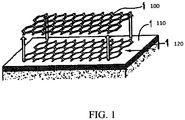
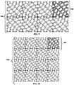
- Figure 1 is a perspective view of a removable rigid template 100 used to leave an impression 110 in a pavement surface 120 as described in US 5,215,402 .
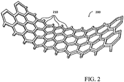
- Figure 2 is a perspective view of a flexible grid 200 defined by frame elements 210 of corresponding shape to the impression 110 provided by the template 100, as shown in Figure 1 .
- FIG 3 is a top plan view of a thermoplastic, rotatable, homogeneous quarter round surface patterned preform 300 for traffic patterns.
- frame elements 210 of the thermoplastic, rotatable, homogeneous quarter round surface patterned preform 300 may define a plurality of open areas 320.
- open areas 320 comprise approximately 50-90% of the total surface area of the thermoplastic, rotatable, homogeneous quarter round surface patterned preform 300.
- closed areas defined by frame elements 210 comprise approximately 10-50% of the total surface area of the thermoplastic, rotatable, homogeneous quarter round surface patterned preform 300.
- Figure 4 is a perspective view of Fig. 3 illustrating the three-dimensional side wall aspect 410 of the thermoplastic, rotatable, homogeneous quarter round surface patterned preform 300.
- Figure 5 is a top view depiction of the various isometries available about a central axis of rotation for the thermoplastic, rotatable, homogeneous quarter round surface patterned preform 300 with surface patterned preform rotation intervals at 0°, 90°, 180°, and 270° respectfully.
- Rotational patterned position A 510 corresponds to a 0° rotation.
- Rotational patterned position B 520 corresponds to a 90° rotation.
- Rotational patterned position C 530 corresponds to a 180° rotation.
- Rotational patterned position D 540 corresponds to a 270° rotation.
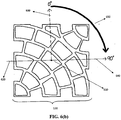
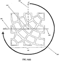
- Figures 6 (a-d) are top view illustrations of isometric thermoplastic, rotatable, homogeneous quarter round surface patterned perform(s) 300.
- Figure 6(a) shows rotational patterned position A 510 with a marked fixed point 610, corresponding to an origin point, through which the x-axis 620 and the y-axis 630 intersect.
- Rotational patterned position A 510 corresponds to a 0° rotation from the y-axis 630.
- Figure 6(b) shows rotational patterned position B 520 with a marked fixed point 610, corresponding to the origin, through which the x-axis 620 and the y-axis 630 intersect.
- Rotational patterned position B 520 corresponds to a 90° rotational position 650 from the y-axis 630.
- Figure 6(c) shows rotational patterned position C 530 with a marked fixed point 610, corresponding to the origin, through which the x-axis 620 and the y-axis 630 intersect.
- Rotational patterned position C 530 corresponds to a 180° rotational position 650 from the y-axis 630.
- Figure 6(d) shows rotational patterned position D 540 with a marked fixed point 610, corresponding to the origin, through which the x-axis 620 and the y-axis 630 intersect.
- Rotational patterned position D 540 corresponds to a 270° rotational position 650 from the y-axis 630.
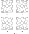
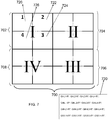
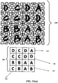
- FIG. 7 is a 4x4 graphical representation of a patterned orthant coding chart 700 for the creation of multiple block pattern portions.
- Quadrant I 702 is located in the top left portion of the patterned orthant coding chart 700 and consists of four (4) individual patterned square locations 720-726 in a 2x2 configuration, with individual patterned square location 1 720 located in the top left quarter of Quadrant I 702, individual patterned square location 2 722 located in the top right quarter of Quadrant I 702, individual patterned square location 3 724 located in the bottom right quarter of Quadrant I 702 and individual patterned square location 4 726 located in the bottom left quarter of Quadrant I 702.
- the position of each individual patterned square location 720, 722, 724, 726 is unchanged in each of the subsequent quadrants II 704, III 706 and IV 708.
- the quadrants 702, 704, 706, 708 are numbered in a clockwise manner, opposite to the otherwise conventional counter-clockwise mathematical custom and individual patterned square locations 1 - 4 720, 722, 724, 726 are clockwise positioned from the individual patterned square location 1720 in each quadrant.
- the coding pattern of rotational patterned positions for Quadrant I 702 can be repeated, or varied, in Quadrants II 704, III 706 and IV 708.
- a written description of the contents of the patterned orthant coding chart 700 can be provided as a patterned orthant coding descriptor 730.
- the patterned orthant coding descriptor 730 describes the quadrant 702-708 (Q#), individual patterned square location 720-726 (L#), and rotational patterned position 710-740 (R*), where # represents the corresponding number and * represents the corresponding letter associated with each position.
- the completed patterned orthant coding descriptor 730 is provided as QI-L1-R*: QI-L2-R*: QI-L3-R*: QI-L4-R*; QII-L1-R*: QII-L2-R*: QII-L3-R*: QII-L4-R*; QIII-L1-R*: QIII-L2-R*: QIII-L3-R*: QIII-L4-R*; QIV-L1-R*: QIV-L2-R*: QIV-L3-R*: QIV-L4-R*.
- Figure 8 is a top plan view of the assembly of a combination of several thermoplastic, rotatable, homogeneous quarter round surface patterned preforms 300 creating a 2x2 patterned preform 800.
- a 2x2 patterned preform 800 contains a single quadrant, Quadrant I 702, and the individual patterned square locations 1-4 720-726 are included within the quadrant.
- Rotational patterned positions C 530, A 510, C 530 and A 510 occupy the individual patterned square locations 1-4 720-726 in placements congruent to the desired 2x2 patterned preform 800.
- Figure 9 is another top plan view of the extended assembly of a plurality of thermoplastic, rotatable, homogeneous quarter round surface patterned preforms 300 assembled in such a manner as to form a robust 2x4 patterned preform 900.
- a 2x4 patterned preform 900 contains two (2) quadrants, Quadrants I 702 and II 704, and the individual patterned square locations 1-4 720-726 included within each quadrant.
- Rotational patterned positions C 530, A 510, C 530 and A 510 occupy the individual patterned square locations 1-4 720-726 in placements congruent to the desired 2x4 patterned preform 900.
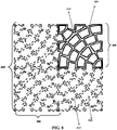
- Figure 10 is an additional top plan view of a further extended assembly of multiple block portions of thermoplastic, rotatable, homogeneous quarter round surface patterned preforms 300 forming a robust 4x4 patterned preform 1000.
- a 4x4 patterned preform 1000 contains Quadrants I 702, II 704, III 706 and IV 708, along with individual patterned square locations 1-4 720-726 included within each quadrant.
- Rotational patterned positions C 530, A 510, C 530 and A 510 occupy the individual patterned square locations 1-4 720-726 in placements congruent to the desired 4x4 patterned preform 1000.
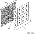
- Figure 11 (a) provides a superimposition 1100 of a patterned orthant coding chart 700, labeled with the desired rotational patterned positions A-D 510-540 onto the desired 4x4 patterned preform 1000.
- Figure 11(b) visually correlates the superimposition 1100 of a patterned orthant coding chart 700 onto the desired 4x4 patterned preform 1000.
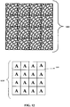
- Figure 12 is a plan elevational view of the completed Uniform pattern 1200 and the uniform coding chart 1210.
- Rotational patterned position A 510 completes the entirety of the uniform coding chart 1210.
- the patterned orthant coding descriptor 730 similar to that shown in Figure 7 , for the uniform coding chart 1210 reads as follows; QI-L1-PA: QI-L2-PA: QI-L3-PA: QI-L4-PA with the coding repeated in all subsequent quadrants.
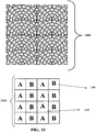
- Figure 13 is a plan elevational view of a completed Scallop pattern 1300 and the scallop coding chart 1310. Alternating rotational patterned position A 510 and rotational patterned position B 520 complete the entirety of the scallop coding chart 1310.
- the patterned orthant coding descriptor 730 similar to that shown in Figure 7 , for the scallop coding chart 1310 reads as follows: QI-L1-PA: QI-L2-PB: QI-L3-PA: QI-L4-PB with the coding repeated in all subsequent quadrants.
- Figure 14 is a plan elevational view of a completed Wheel pattern 1400 and the wheel coding chart 1410. Clockwise rotation of the rotational patterned positions A 510, B 520, C 530 and D 540 complete the entirety of the wheel coding chart 1410.
- the patterned orthant coding descriptor 730 similar to that shown in Figure 7 , for the wheel coding chart 1410 reads as follows; QI-L1-PA: QI-L2-PB: QI-L3-PC: QI-L4-PD with the coding repeated in all subsequent quadrants.
- Figure 15 is a plan elevational view of a completed Stacked Wheel pattern 1500 and the stacked wheel coding chart 1510. Alternating rotational patterned position A 510 and rotational patterned position B 520 complete the entirety of the stacked wheel coding chart 1510.
- the patterned orthant coding descriptor 730 similar to that shown in Figure 7 , for the scallop coding chart 1510 reads as follows; QI-L1-PA: QI-L2-PB: QI-L3-PB: QI-L4-PA with the coding repeated in all subsequent quadrants.
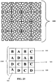
- Figure 16 is a plan elevational view of a completed Star pattern 1600 and the star coding chart 1610. Rotational patterned positions A 510, B 520, C 530 and D 540 complete the entirety of the star coding chart 1610.
- the patterned orthant coding descriptor 730 similar to that shown in Figure 7 , for the star coding chart 1610 reads as follows; QI-L1-RD: QI-L2-RC: QI-L3-RC: QI-L4-RC; QII-L1-RD: QII-L2-RA: QII-L3-RD: QII-L4-RD; QIII-L1-RA: QIII-L2-RA: QIII-L3-RB: QIII-L4-RA; QIV-L1-RB: QIV-L2-RB: QIV-L3-RB: QIV-L4-RC.
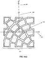
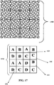
- Figure 17 is a plan elevational view of a completed Clover pattern 1700 and the clover coding chart 1710. Rotational patterned positions A 510, B 520, C 530 and D 540 complete the entirety of the star coding chart 1710.
- the patterned orthant coding descriptor 730 similar to that shown in Figure 7 , for the clover coding chart 1710 reads as follows; QI-L1-RA: QI-L2-RB: QI-L3-RB: QI-L4-RD; QII-L1-RA: QII-L2-RB: QII-L3-RC: QII-L4-RC; QIII-L1-RD: QIII-L2-RB: QIII-L3-RC: QIII-L4-RD; QIV-L1-RA: QIV-L2-RA: QIV-L3-RC: QIV-L4-RD.
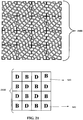
- Figure 18 is a plan elevational view of a completed Inverted Wave pattern 1800 and the inverted wave coding chart 1810. Rotational patterned positions A 510, B 520, C 530 and D 540 complete the entirety of the inverted coding chart 1810.
- the patterned orthant coding descriptor 730 similar to that shown in Figure 7 , for the inverted wave coding chart 1810 reads as follows; QI-L1-RB: QI-L2-RB: QI-L3-RD: QI-L4-RD; QIII-L1-RA: QIII-L2-RA: QIII-L3-RC: QIII-L4-RC. Coding for Quadrants II 704 and IV 708 correspond to the coding for Quadrants I 702 and III 706, respectively.
- Figure 19 is a plan elevational view of a completed Translated Wavy pattern 1900 and the translated wavy coding chart 1910.
- Rotational patterned positions A 510, B 520, C 530 and D 540 complete the entirety of the translated wavy coding chart 1910.
- the patterned orthant coding descriptor 730, similar to that shown in Figure 7 , for the translated wavy coding chart 1910 reads as follows; QI-L1-RA: QI-L2-RB: QI-L3-RD: QI-L4-RC with the coding repeated in all subsequent quadrants.
- Figure 20 is a plan elevational view of a completed Reflected Wavy pattern 2000 and the reflected wavy coding chart 2010. Rotational patterned positions A 510, B 520, C 530 and D 540 complete the entirety of the reflected wavy coding chart 2010.
- the patterned orthant coding descriptor 730 similar to that shown in Figure 7 , for the reflected wavy coding chart 2010 reads as follows; QI-L1-RA: QI-L2-RB: QI-L3-RD: QI-L4-RC; QII-L1-RA: QII-L2-RB: QII-L3-RD: QII-L4-RC; QIII-L1-RB: QIII-L2-RA: QIII-L3-RC: QIII-L4-RD; QIV-L1-RB: QIV-L2-RA: QIV-L3-RC: QIV-L4-RD. Coding for Quadrants II 704 and IV 708 correspond to the coding for Quadrants I 702 and III 706, respectively.
- Figure 21 is a plan elevational view of a completed Alternating Inverted Wavy pattern 2100 and the alternating inverted wavy coding chart 2110.
- Alternating rotational patterned position B 520 and rotational patterned position D 540 complete the entirety of the alternating inverted wavy coding chart 2110.
- the patterned orthant coding descriptor 730 similar to that shown in Figure 7 , for the alternating inverted wavy coding chart 2110 reads as follows; QI-L1-PD: QI-L2-PB: QI-L3-PD: QI-L4-PB with the coding repeated in all subsequent quadrants.
- Figure 22 is a plan elevational view of a completed Swirled Wave pattern 2200 and the swirled wave coding chart 2210.
- Rotational patterned positions A 510, B 520, C 530 and D 540 complete the entirety of a swirled wave coding chart 2210.
- the individual patterned square locations 3 724 and 4 726 of each quadrant 702-708 are skewed in order to complete this pattern, as provided by prime notation 2212.
- the patterned orthant coding descriptor 730 similar to that shown in Figure 7 , for the swirled wave coding chart 2210 reads as follows; QI-L1-RA: QI-L2-RB: QI-L3-RC': QI-L4-RD'; QIII-L1-RB: QIII-L2-RA: QIII-L3-RD': QIII-L4-RC'. Coding for Quadrants II 704 and IV 708 correspond to the coding for Quadrants I 702 and III 706, respectively.
- Figure 23 is a plan elevational view of a completed Stacked Wheel pattern 2300 and the stacked wheel coding chart 2310. Rotational patterned positions A 510, B 520, C 530 and D 540 complete the entirety of the stacked wheel coding chart 2310.
- the patterned orthant coding descriptor 730 similar to that shown in Figure 7 , for the stacked wheel coding chart 2310 reads as follows; QI-L1-RB: QI-L2-RA: QI-L3-RD: QI-L4-RA; QII-L1-RB: QII-L2-RC: QII-L3-RB: QII-L4-RA; QIII-L1-RB: QIII-L2-RC: QIII-L3-RD: QIII-L4-RC; QIV-L1-RD: QIV-L2-RC: QIV-L3-RD: QIV-L4-RA.
Landscapes
- Engineering & Computer Science (AREA)
- Architecture (AREA)
- Civil Engineering (AREA)
- Structural Engineering (AREA)
- Mining & Mineral Resources (AREA)
- Editing Of Facsimile Originals (AREA)
- Floor Finish (AREA)
Description
- The present invention relates to a method of forming multiple inlaid patterns onto or into an asphalt surface from a single thermoplastic rotatable, homogeneous quarter round surface patterned preform. The pattern may be selected for functional or decorative purposes.
- Various methods for forming patterns in asphalt surfaces are known in the related art. The Applicant is the owner of
U.S. Pat. No. 5,215,402 , which describes a method of forming a pattern in an asphalt surface using a removable template. The template is compressed into a pliable asphalt surface to imprint a predetermined pattern simulating, for example, the appearance of bricks, cobblestones, interlocking paving stones or the like. The template is then lifted clear of the asphalt surface and the asphalt is allowed to harden. A thin layer of a cementitious coating may be applied to the imprinted asphalt to enhance the brick and mortar or other desired effect. A similar method is known fromUS 2005/0089372 A1 . - In the above-described method the template does not remain inlaid within the asphalt surface. The visual effect is created by the combination of the imprinted pattern and the decorative coating. One very important and distinctive drawback to this method is that the decorative coating may wear off over time, particularly in high traffic areas.
-
CA 931440 discloses a method for forming different patterns and designs of varied colors, textures, and levels through the use of specially designed templates or grids which are used in the application of bonding liquids and color granules or chips to produce a decorative finish on varied types of surfaces including floors and building materials. - It also known that it is possible to install traffic markings on asphalt surfaces. However, such markings typically extend and project above the asphalt surface and are relatively bulky. In regions receiving frequent snowfalls during the winter months, traffic markings may often be removed or damaged during snowplow usage.
- Another known method for producing traffic markings involves grinding grooves in asphalt surfaces and then pouring into these grooves a hot molten material which is allowed to set in place. However, this is a very time consuming procedure, and is not well suited for forming complicated patterns, or covering large surface areas. The need therefore exists and remains for improved methods and materials needed to provide inlayed patterns in asphalt surfaces.
- In accordance with the invention, a method of forming multiple inlaid patterns into or onto an asphalt surface from a single homogeneous, rotatable quarter round surface patterned preform is disclosed. The method of forming multiple inlaid patterns to complete a final predetermined rotational pattern onto or into a pavement surface includes the steps of:
- (a) providing a template for creating multiple blocks with portions of rotational isometric patterns;
- (b) impressing the template into the pavement surface when the surface is in a pliable state to form an impression therein;
- (c) removing the template from the surface to expose the impression;
- (d) providing an inlaid rotatable preform grid that at least partially matches the pattern of the template;
- (e) inserting the rotatable preform grid into the impression caused by the template;
- (f) fixing the rotatable preform grid in position within the impression to form the inlaid pattern;
- (g) creating multiple blocks of the portions of the patterns such that rotational isometric patterns form a final rotational predetermined isometric patterned preform.
- The method may include the step of heating the asphalt surface prior to impressing the template into the asphalt surface.
- The method of step (a) includes determining the location of each preform isometry in the predetermined pattern. The decided locality of the thermoplastic, rotatable, homogeneous quarter round surface patterned preform within the predetermined pattern is determined by a combination of quadrant, location and rotation within a coded chart, wherein the final rotational predetermined isometric patterned preform is formed using patterned orthant coding descriptors describing quadrants designated as (Q#), individual patterned square locations designated as (L#), and rotational patterned positions designated as (R*), where # represents the corresponding location or quadrant number and * represents the corresponding letter associated with each angular rotational position expressed in degrees from a vertical y-axis. Multiple patterned templates and/or grids are constructed from a single isometric preform (quarter round portion) that is provided in various combinations. This single isometric preform is repeated using quadrant, location, and rotational positioning. The predetermined pattern may serve a specific function such as a crosswalk marking, or it may be purely decorative.
- The impression may consist of a plurality of channels or simulated grout lines. By way of another embodiment, the impression may be the outline of a corporate logo or decorative design. Grids may be manufactured in mats approximately 2' by 2' in size for ease of handling. Multiple grids may be arranged to cover a large surface area. The grids could be arranged so that the frame elements of adjacent grids are partially overlapping at the joinder sites. The gradual heating method described above could be continued until the overlapping frame elements melt together and adhere.
- The step of fixing the grid in position within the impression comprises heating the grid to cause the grid to bond to the asphalt surface. For example, the grid may be heated to a temperature within the range of about 38°C to 204°C (100 degrees Fahrenheit to 400 degrees Fahrenheit) and more preferably within the range of 66°C to 177°C (150 degrees Fahrenheit to 350 degrees Fahrenheit), depending on the type of asphalt.
- The grid may be comprised of a preformed thermoplastic of unitary construction. The color of the grid may be selected to contrast with the color of the asphalt surface. In another embodiment the grid may include retroreflective elements or a mixture of retroreflective elements and other additives. In one embodiment the grid may be constructed from a skid-resistant material and/or contain skid resistant additives.
- In a further alternative embodiment the template and grid may include a plurality of frame elements defining open areas therebetween, the open areas comprising approximately 50-90 percent of the total surface area of each template and/or grid.
- In one embodiment the grid may comprise an upper surface which is substantially flush with the surface of the asphalt when the grid is fixed in position. Alternatively, a portion of the grid may be raised above the asphalt surface or recessed below the asphalt surface when it is set in place.
- The template and grid may be formed from a plurality of frame elements each having a relatively narrow width to facilitate compression of the template and/or grid into the asphalt surface without the need to apply substantial compactive force. For example, the frame elements may normally have a width between 6 mm (1/4 inch) and 10 cm (4 inches). The thickness of the grid is normally between 2 and 2.5 mm (80 and 100 mil) and the thickness of the template is between 3.2 and 5 mm (125 and 200 mil).
- In an alternative embodiment the grid may be compressed into the asphalt surface directly while the asphalt surface is in a pliable state and without deforming the desired predetermined pattern. The grid is then fixed in place as in the embodiment described above.
- In another alternative embodiment, the single isometric thermoplastic, rotatable, homogeneous quarter round surface patterned preform is produced as thermoplastic sheeting, as described in commonly owned
U.S. Patent No. 7,645,503 , composed of two or more independent sections. The first section is a grid, which in one specific case replicates the appearance of mortar joints as they would form a brick wall. An additional or second section could for example, replicate bricks which are contained within the grid section. The first and second sections possess a hot melt adhesive spray that is utilized on the bottom surface of the marking pattern to bridge the intersections between the first and second sections to maintain the integrity of the marking pattern for convenience during handling and application to a substrate and packaged for shipment. Preferably the hot melt spray adhesive has approximately the same softening point range as the patterned sections, to accommodate heat treatment of the marking pattern during application of the marking pattern to the substrate and eventually to the pavement. In this embodiment, the grid could be replaced by continuous thermoplastic sheets formed in the desired shape and pattern. These thermoplastic sheets may not be inlaid into the pavement but may nevertheless be gently heated as described above to adhere to the underlying asphalt substrate. - In a further embodiment the grid comprises a retroflective element including glass beads and skid resistant element that provides the template with retroflective capabilities after the template is fixed in position within said impression.
- Another further embodiment provides the grid as luminescent and/ or fluorescent.
- In another embodiment the preform can be used for comparatively large thermoplastic surfaces, such as corporate logos, traffic markings, pedestrian walkways, driveways or the like.
- The drawings listed as
Figures 1-23 below are precise embodiments of the invention, but should not be construed as restricting the spirit or scope of the invention in any way, -
FIG. 1 is a perspective view of a removable rigid template used to impress a pavement surface, according toUS 5,215,402 . -
FIG. 2 is a perspective view of an example of a flexible grid used to fill an impressed pavement surface ofFig. 1 . -
FIG. 3 is a top plan view of a thermoplastic rotatable, homogeneous quarter round surface patterned preform for traffic patterns. -
FIG. 4 is a perspective view ofFig. 3 . -
FIG. 5 is a top plan view of surface patterned preform in rotational patterned positions. -
FIGS. 6 (a-d) display the rotational patterned positions as they are revolved about a central axis. -
FIG.7 is a graphical representation of a coordinate coding chart for the reproducible assembly of a combination of several thermoplastic, rotatable surface patterned preforms. -
FIG. 8 is a top plan view of the assembly of a combination of several thermoplastic, rotatable surface patterned preforms creating a specially designated design portion of the desired pattern. -
FIG. 9 is a top plan view of an extended assembly of a plurality of pattern preforms assembled in such a manner as to complete the robust design with the associated desired pattern. -
FIG. 10 is another top plan view of an additional extended assembly with multiple block portions providing the robust pattern design with the associated desired pattern. -
FIGS. 11 (a-b) depict visual correlations of a completed pattern with the corresponding coordinate coding chart. -
FIG. 12 is an aerial perspective of an embodiment of a completed design, displaying a uniform pattern coding of identical rotational patterned positions and the corresponding pattern coding chart. -
FIG. 13 is a plan elevational view of an embodiment of a completed design, displaying a scallop pattern coding of rotational patterned positions and the corresponding pattern coding chart. -
FIG. 14 is a plan elevational view of an embodiment of a completed design, displaying a wheel pattern coding of rotational patterned positions and the corresponding pattern coding chart. -
FIG. 15 is a plan elevational view of an embodiment of a completed design, displaying a stacked arch pattern coding of rotational patterned positions and the corresponding pattern coding chart. -
FIG. 16 is a plan elevational view of an embodiment of a completed design, displaying a star pattern coding of rotational patterned positions and the corresponding pattern coding chart. -
FIG. 17 is a plan elevational view of an embodiment of a completed design, displaying a clover pattern coding of rotational patterned positions and the corresponding pattern coding chart. -
FIG. 18 is a plan elevational view of an embodiment of a completed design, displaying an inverted wave pattern coding of rotational patterned positions and the corresponding pattern coding chart. -
FIG. 19 is a plan elevational view of an embodiment of a completed design, displaying a translated wavy pattern coding of rotational patterned positions and the corresponding pattern coding chart. -
FIG. 20 is a plan elevational view of an embodiment of a completed design, displaying a reflected wavy pattern coding of rotational patterned positions and the corresponding pattern coding chart. -
FIG. 21 is a plan elevational view of an embodiment of a completed design, displaying an alternating inverted wavy pattern coding of rotational patterned positions and the corresponding pattern coding chart. -
FIG. 22 is a plan elevational view of an embodiment of a completed design, displaying a swirled wave pattern coding of rotational patterned positions and the corresponding pattern coding chart. -
FIG. 23 is a plan elevational view of an embodiment of a completed design, displaying a stacked wheel pattern coding of rotational patterned positions and the corresponding pattern coding chart. -
Figure 1 is a perspective view of a removablerigid template 100 used to leave an impression 110 in apavement surface 120 as described inUS 5,215,402 . -
Figure 2 is a perspective view of aflexible grid 200 defined byframe elements 210 of corresponding shape to the impression 110 provided by thetemplate 100, as shown inFigure 1 . -
Figure 3 is a top plan view of a thermoplastic, rotatable, homogeneous quarter round surface patternedpreform 300 for traffic patterns. As shown inFigure 2 ,frame elements 210 of the thermoplastic, rotatable, homogeneous quarter round surface patternedpreform 300 may define a plurality ofopen areas 320. In one embodiment of the invention,open areas 320 comprise approximately 50-90% of the total surface area of the thermoplastic, rotatable, homogeneous quarter round surface patternedpreform 300. Conversely closed areas defined byframe elements 210 comprise approximately 10-50% of the total surface area of the thermoplastic, rotatable, homogeneous quarter round surface patternedpreform 300. -
Figure 4 is a perspective view ofFig. 3 illustrating the three-dimensionalside wall aspect 410 of the thermoplastic, rotatable, homogeneous quarter round surface patternedpreform 300. -
Figure 5 is a top view depiction of the various isometries available about a central axis of rotation for the thermoplastic, rotatable, homogeneous quarter round surface patternedpreform 300 with surface patterned preform rotation intervals at 0°, 90°, 180°, and 270° respectfully. Rotationalpatterned position A 510 corresponds to a 0° rotation. Rotationalpatterned position B 520 corresponds to a 90° rotation. Rotationalpatterned position C 530 corresponds to a 180° rotation. Rotationalpatterned position D 540 corresponds to a 270° rotation. -
Figures 6 (a-d) are top view illustrations of isometric thermoplastic, rotatable, homogeneous quarter round surface patterned perform(s) 300.Figure 6(a) shows rotationalpatterned position A 510 with a markedfixed point 610, corresponding to an origin point, through which thex-axis 620 and the y-axis 630 intersect. Rotationalpatterned position A 510 corresponds to a 0° rotation from the y-axis 630.Figure 6(b) shows rotationalpatterned position B 520 with a markedfixed point 610, corresponding to the origin, through which thex-axis 620 and the y-axis 630 intersect. Rotationalpatterned position B 520 corresponds to a 90°rotational position 650 from the y-axis 630.Figure 6(c) shows rotationalpatterned position C 530 with a markedfixed point 610, corresponding to the origin, through which thex-axis 620 and the y-axis 630 intersect. Rotationalpatterned position C 530 corresponds to a 180°rotational position 650 from the y-axis 630.Figure 6(d) shows rotationalpatterned position D 540 with a markedfixed point 610, corresponding to the origin, through which thex-axis 620 and the y-axis 630 intersect. Rotationalpatterned position D 540 corresponds to a 270°rotational position 650 from the y-axis 630. -
Figure 7 is a 4x4 graphical representation of a patternedorthant coding chart 700 for the creation of multiple block pattern portions. Quadrant I 702 is located in the top left portion of the patternedorthant coding chart 700 and consists of four (4) individual patterned square locations 720-726 in a 2x2 configuration, with individual patternedsquare location 1 720 located in the top left quarter of Quadrant I 702, individual patternedsquare location 2 722 located in the top right quarter of Quadrant I 702, individual patternedsquare location 3 724 located in the bottom right quarter of Quadrant I 702 and individual patternedsquare location 4 726 located in the bottom left quarter of Quadrant I 702. The position of each individual patternedsquare location III 706 andIV 708. - The
quadrants Quadrants II 704,III 706 andIV 708. - A written description of the contents of the patterned
orthant coding chart 700 can be provided as a patternedorthant coding descriptor 730. The patternedorthant coding descriptor 730 describes the quadrant 702-708 (Q#), individual patterned square location 720-726 (L#), and rotational patterned position 710-740 (R*), where # represents the corresponding number and * represents the corresponding letter associated with each position. The completed patternedorthant coding descriptor 730 is provided as QI-L1-R*: QI-L2-R*: QI-L3-R*: QI-L4-R*; QII-L1-R*: QII-L2-R*: QII-L3-R*: QII-L4-R*; QIII-L1-R*: QIII-L2-R*: QIII-L3-R*: QIII-L4-R*; QIV-L1-R*: QIV-L2-R*: QIV-L3-R*: QIV-L4-R*. -
Figure 8 is a top plan view of the assembly of a combination of several thermoplastic, rotatable, homogeneous quarter round surface patterned preforms 300 creating a 2x2 patternedpreform 800. A 2x2 patternedpreform 800 contains a single quadrant, Quadrant I 702, and the individual patterned square locations 1-4 720-726 are included within the quadrant. Rotationalpatterned positions C 530, A 510,C 530 and A 510 occupy the individual patterned square locations 1-4 720-726 in placements congruent to the desired 2x2 patternedpreform 800. -
Figure 9 is another top plan view of the extended assembly of a plurality of thermoplastic, rotatable, homogeneous quarter round surface patterned preforms 300 assembled in such a manner as to form a robust 2x4 patternedpreform 900. A 2x4 patternedpreform 900 contains two (2) quadrants, Quadrants I 702 and II 704, and the individual patterned square locations 1-4 720-726 included within each quadrant. Rotationalpatterned positions C 530, A 510,C 530 and A 510 occupy the individual patterned square locations 1-4 720-726 in placements congruent to the desired 2x4 patternedpreform 900. -
Figure 10 is an additional top plan view of a further extended assembly of multiple block portions of thermoplastic, rotatable, homogeneous quarter round surface patterned preforms 300 forming a robust 4x4 patternedpreform 1000. A 4x4 patternedpreform 1000 contains Quadrants I 702, II 704,III 706 andIV 708, along with individual patterned square locations 1-4 720-726 included within each quadrant. Rotationalpatterned positions C 530, A 510,C 530 and A 510 occupy the individual patterned square locations 1-4 720-726 in placements congruent to the desired 4x4 patternedpreform 1000. -
Figure 11 (a) provides asuperimposition 1100 of a patternedorthant coding chart 700, labeled with the desired rotational patterned positions A-D 510-540 onto the desired 4x4 patternedpreform 1000.Figure 11(b) visually correlates thesuperimposition 1100 of a patternedorthant coding chart 700 onto the desired 4x4 patternedpreform 1000. -
Figure 12 is a plan elevational view of the completedUniform pattern 1200 and theuniform coding chart 1210. Rotationalpatterned position A 510 completes the entirety of theuniform coding chart 1210. The patternedorthant coding descriptor 730, similar to that shown inFigure 7 , for theuniform coding chart 1210 reads as follows; QI-L1-PA: QI-L2-PA: QI-L3-PA: QI-L4-PA with the coding repeated in all subsequent quadrants. -
Figure 13 is a plan elevational view of a completedScallop pattern 1300 and thescallop coding chart 1310. Alternating rotationalpatterned position A 510 and rotationalpatterned position B 520 complete the entirety of thescallop coding chart 1310. The patternedorthant coding descriptor 730, similar to that shown inFigure 7 , for thescallop coding chart 1310 reads as follows: QI-L1-PA: QI-L2-PB: QI-L3-PA: QI-L4-PB with the coding repeated in all subsequent quadrants. -
Figure 14 is a plan elevational view of a completedWheel pattern 1400 and thewheel coding chart 1410. Clockwise rotation of the rotational patterned positions A 510,B 520,C 530 andD 540 complete the entirety of thewheel coding chart 1410. The patternedorthant coding descriptor 730, similar to that shown inFigure 7 , for thewheel coding chart 1410 reads as follows; QI-L1-PA: QI-L2-PB: QI-L3-PC: QI-L4-PD with the coding repeated in all subsequent quadrants. -
Figure 15 is a plan elevational view of a completedStacked Wheel pattern 1500 and the stackedwheel coding chart 1510. Alternating rotationalpatterned position A 510 and rotationalpatterned position B 520 complete the entirety of the stackedwheel coding chart 1510. The patternedorthant coding descriptor 730, similar to that shown inFigure 7 , for thescallop coding chart 1510 reads as follows; QI-L1-PA: QI-L2-PB: QI-L3-PB: QI-L4-PA with the coding repeated in all subsequent quadrants. -
Figure 16 is a plan elevational view of a completedStar pattern 1600 and thestar coding chart 1610. Rotational patterned positions A 510,B 520,C 530 andD 540 complete the entirety of thestar coding chart 1610. The patternedorthant coding descriptor 730, similar to that shown inFigure 7 , for thestar coding chart 1610 reads as follows; QI-L1-RD: QI-L2-RC: QI-L3-RC: QI-L4-RC; QII-L1-RD: QII-L2-RA: QII-L3-RD: QII-L4-RD; QIII-L1-RA: QIII-L2-RA: QIII-L3-RB: QIII-L4-RA; QIV-L1-RB: QIV-L2-RB: QIV-L3-RB: QIV-L4-RC. -
Figure 17 is a plan elevational view of a completedClover pattern 1700 and theclover coding chart 1710. Rotational patterned positions A 510,B 520,C 530 andD 540 complete the entirety of thestar coding chart 1710. The patternedorthant coding descriptor 730, similar to that shown inFigure 7 , for theclover coding chart 1710 reads as follows; QI-L1-RA: QI-L2-RB: QI-L3-RB: QI-L4-RD; QII-L1-RA: QII-L2-RB: QII-L3-RC: QII-L4-RC; QIII-L1-RD: QIII-L2-RB: QIII-L3-RC: QIII-L4-RD; QIV-L1-RA: QIV-L2-RA: QIV-L3-RC: QIV-L4-RD. -
Figure 18 is a plan elevational view of a completedInverted Wave pattern 1800 and the invertedwave coding chart 1810. Rotational patterned positions A 510,B 520,C 530 andD 540 complete the entirety of theinverted coding chart 1810. The patternedorthant coding descriptor 730, similar to that shown inFigure 7 , for the invertedwave coding chart 1810 reads as follows; QI-L1-RB: QI-L2-RB: QI-L3-RD: QI-L4-RD; QIII-L1-RA: QIII-L2-RA: QIII-L3-RC: QIII-L4-RC. Coding for Quadrants II 704 andIV 708 correspond to the coding for Quadrants I 702 andIII 706, respectively. -
Figure 19 is a plan elevational view of a completed TranslatedWavy pattern 1900 and the translatedwavy coding chart 1910. Rotational patterned positions A 510,B 520,C 530 andD 540 complete the entirety of the translatedwavy coding chart 1910. The patternedorthant coding descriptor 730, similar to that shown inFigure 7 , for the translatedwavy coding chart 1910 reads as follows; QI-L1-RA: QI-L2-RB: QI-L3-RD: QI-L4-RC with the coding repeated in all subsequent quadrants. -
Figure 20 is a plan elevational view of a completed ReflectedWavy pattern 2000 and the reflectedwavy coding chart 2010. Rotational patterned positions A 510,B 520,C 530 andD 540 complete the entirety of the reflectedwavy coding chart 2010. The patternedorthant coding descriptor 730, similar to that shown inFigure 7 , for the reflectedwavy coding chart 2010 reads as follows; QI-L1-RA: QI-L2-RB: QI-L3-RD: QI-L4-RC; QII-L1-RA: QII-L2-RB: QII-L3-RD: QII-L4-RC; QIII-L1-RB: QIII-L2-RA: QIII-L3-RC: QIII-L4-RD; QIV-L1-RB: QIV-L2-RA: QIV-L3-RC: QIV-L4-RD. Coding for Quadrants II 704 andIV 708 correspond to the coding for Quadrants I 702 andIII 706, respectively. -
Figure 21 is a plan elevational view of a completed Alternating InvertedWavy pattern 2100 and the alternating invertedwavy coding chart 2110. Alternating rotationalpatterned position B 520 and rotationalpatterned position D 540 complete the entirety of the alternating invertedwavy coding chart 2110. The patternedorthant coding descriptor 730, similar to that shown inFigure 7 , for the alternating invertedwavy coding chart 2110 reads as follows; QI-L1-PD: QI-L2-PB: QI-L3-PD: QI-L4-PB with the coding repeated in all subsequent quadrants. -
Figure 22 is a plan elevational view of a completed SwirledWave pattern 2200 and the swirledwave coding chart 2210. Rotational patterned positions A 510,B 520,C 530 andD 540 complete the entirety of a swirledwave coding chart 2210. The individual patternedsquare locations 3 724 and 4 726 of each quadrant 702-708 are skewed in order to complete this pattern, as provided by prime notation 2212. The patternedorthant coding descriptor 730, similar to that shown inFigure 7 , for the swirledwave coding chart 2210 reads as follows; QI-L1-RA: QI-L2-RB: QI-L3-RC': QI-L4-RD'; QIII-L1-RB: QIII-L2-RA: QIII-L3-RD': QIII-L4-RC'. Coding for Quadrants II 704 andIV 708 correspond to the coding for Quadrants I 702 andIII 706, respectively. -
Figure 23 is a plan elevational view of a completedStacked Wheel pattern 2300 and the stackedwheel coding chart 2310. Rotational patterned positions A 510,B 520,C 530 andD 540 complete the entirety of the stackedwheel coding chart 2310. The patternedorthant coding descriptor 730, similar to that shown inFigure 7 , for the stackedwheel coding chart 2310 reads as follows; QI-L1-RB: QI-L2-RA: QI-L3-RD: QI-L4-RA; QII-L1-RB: QII-L2-RC: QII-L3-RB: QII-L4-RA; QIII-L1-RB: QIII-L2-RC: QIII-L3-RD: QIII-L4-RC; QIV-L1-RD: QIV-L2-RC: QIV-L3-RD: QIV-L4-RA.
Claims (11)
- A method of forming multiple inlaid patterns to complete a final predetermined rotational pattern onto or into a pavement surface (120) comprising:(a) providing a template (100) for creating multiple blocks with portions of rotational isometric patterns;(b) impressing said template into said pavement surface (120) when said surface is in a pliable state to form an impression (110) therein;(c) removing said template from said surface to expose said impression (110);(d) providing an inlaid rotatable isometric preform grid (300) that at least partially matches the pattern of said template;(e) inserting said rotatable preform grid (300) into said impression (110) caused by said template;(f) fixing said rotatable preform grid (300) in position within said impression (110) to form said inlaid pattern; thereby;(g) creating multiple blocks of said portions of said patterns such that multiple rotational isometric patterns form a final rotational predetermined isometric patterned preform (800, 900, 1000),wherein said final rotational predetermined isometric patterned preform is formed using patterned orthant coding descriptors for the location of each rotatable preform grid in said final patterned preform, the descriptors describing quadrants designated as Q#, individual patterned square locations (720) designated as L#, and rotational patterned positions designated as R*, where # represents the corresponding location or quadrant number and * represents the corresponding letter associated with each angular rotational position (650) expressed in degrees from a vertical y-axis (630).
- The method of forming an inlaid pattern of claim 1 , wherein after the preceding step (f), fixing said grid in position within impressions for forming said inlaid patterns is accomplished by passing a portable heater over the surface of said grid.
- The method of claim 1 or 2, wherein said pavement surface (120) is asphalt and may comprise the step of heating said asphalt surface prior to impressing said template into the asphalt surface.
- The method of one of the preceding claims, wherein the step of fixing said grid in position within said impression comprises heating said grid after insertion of said grid into said impression to cause said grid to bond to said pavement surface (120).
- The method of claim 4, wherein said grid is heated to a temperature within the range of approximately 38 to 204°C (100 to 400 degrees Fahrenheit), more specifically 66 to 177°C (150 to 350 degrees Fahrenheit).
- The method of one of the preceding claims, wherein said grid comprises a preformed thermoplastic pattern and / or said grid is of unitary construction and / or said grid has a color contrasting with the color of said pavement surface (120).
- The method of one of the preceding claims, wherein said grid comprises retroflective elements including glass beads and skid resistant elements that provide said template retroflective capabilities after said template is fixed in position within said impression.
- The method of claim 7, wherein said grid is luminescent or flourescent.
- The method of one of the preceding claims, wherein said grid is a preform (300) with a plurality of frame elements (210) prior to inserting said grid into said impression, and wherein the preform (300) frame elements (210) have a width less than 30 cm (12 inches) more specifically between 6 mm (1/4 inch) and 10 cm (4 inches).
- The method of one of the preceding claims, wherein said predetermined pattern is decorative and / or non-linear.
- The method of claim 5, wherein said heating comprises passing a portable surface heater over an upper surface of said grid after said grid has been inserted into said impression.
Priority Applications (1)
| Application Number | Priority Date | Filing Date | Title |
|---|---|---|---|
| PL13862560T PL2931975T3 (en) | 2012-12-13 | 2013-12-13 | Method of forming an inlaid pattern in an asphalt surface. |
Applications Claiming Priority (2)
| Application Number | Priority Date | Filing Date | Title |
|---|---|---|---|
| US13/713,188 US8864409B2 (en) | 2012-12-13 | 2012-12-13 | Method of forming an inlaid pattern in an asphalt surface from preformed template isometries |
| PCT/US2013/000274 WO2014092748A1 (en) | 2012-12-13 | 2013-12-13 | Method of forming an inlaid pattern in an asphalt surface. |
Publications (3)
| Publication Number | Publication Date |
|---|---|
| EP2931975A1 EP2931975A1 (en) | 2015-10-21 |
| EP2931975A4 EP2931975A4 (en) | 2016-04-06 |
| EP2931975B1 true EP2931975B1 (en) | 2017-10-04 |
Family
ID=50931057
Family Applications (1)
| Application Number | Title | Priority Date | Filing Date |
|---|---|---|---|
| EP13862560.3A Not-in-force EP2931975B1 (en) | 2012-12-13 | 2013-12-13 | Method of forming an inlaid pattern in an asphalt surface. |
Country Status (9)
| Country | Link |
|---|---|
| US (1) | US8864409B2 (en) |
| EP (1) | EP2931975B1 (en) |
| CA (1) | CA2895181C (en) |
| DK (1) | DK2931975T3 (en) |
| ES (1) | ES2655992T3 (en) |
| NO (1) | NO3011643T3 (en) |
| PL (1) | PL2931975T3 (en) |
| PT (1) | PT2931975T (en) |
| WO (1) | WO2014092748A1 (en) |
Families Citing this family (6)
| Publication number | Priority date | Publication date | Assignee | Title |
|---|---|---|---|---|
| US9732481B2 (en) | 2004-04-02 | 2017-08-15 | Flint Trading, Inc. | Preformed thermoplastic pavement marking and method utilizing large aggregate for improved long term skid resistance and reduced tire tracking |
| US10611134B2 (en) | 2009-11-25 | 2020-04-07 | Mark Brendan Lamar | Groutless patterns for pavement surfaces using thermoplastic preforms |
| US20140272237A1 (en) * | 2013-03-15 | 2014-09-18 | Prc-Desoto International, Inc. | Strippable film assembly and coating for drag reduction |
| US10221527B2 (en) * | 2014-07-28 | 2019-03-05 | W. Robert Wilson | Dry polymer cement overlay for trafficked pavements |
| US10654751B2 (en) * | 2016-05-25 | 2020-05-19 | W. Robert Wilson | Polymer modified cement adhesive for providing high friction surfacing |
| US11242660B1 (en) | 2019-02-08 | 2022-02-08 | Preform LLC | Preformed reflective line marking for roadways and associated methods thereof |
Family Cites Families (49)
| Publication number | Priority date | Publication date | Assignee | Title |
|---|---|---|---|---|
| US1063752A (en) | 1911-10-25 | 1913-06-03 | William Fred Walling | Machine for making imitation-tile flooring. |
| US1950163A (en) | 1933-03-17 | 1934-03-06 | Herbert F Apple | Accelerator controlled automotive transmission |
| US2196890A (en) | 1937-09-23 | 1940-04-09 | John N Bensen | Traffic marker and indicium |
| US2237152A (en) | 1938-11-21 | 1941-04-01 | Plastic Inlays Inc | Method of inlaying articles |
| US2595142A (en) | 1949-02-12 | 1952-04-29 | Ce Brick Corp | Method for producing designs on building walls |
| US2866992A (en) | 1954-10-15 | 1959-01-06 | Ohio Commw Eng Co | Road marking apparatus |
| US2898825A (en) | 1955-06-20 | 1959-08-11 | Limark Corp | Marking stripe and method of applying same |
| US3410185A (en) | 1966-08-08 | 1968-11-12 | Minnesota Mining & Mfg | Marking |
| US3664242A (en) | 1970-06-15 | 1972-05-23 | Minnesota Mining & Mfg | Method for marking roadways |
| CA931440A (en) * | 1970-12-29 | 1973-08-07 | E. Smith Sam | Method for fabricating a seamless plastic surface having an embossed, multicolored, textured, and patterned appearance |
| US3874806A (en) | 1972-07-27 | 1975-04-01 | Cmi Corp | Apparatus for grooving pavement |
| US3910711A (en) | 1972-08-10 | 1975-10-07 | William V Moorhead | Concrete forming apparatus |
| US3832079A (en) | 1972-08-10 | 1974-08-27 | W Moorhead | Concrete forming apparatus and process |
| IT1049350B (en) | 1975-01-24 | 1981-01-20 | Eigenmann Ludwig | METHOD AND DEVICE FOR THE PREPARATION OF ROAD SURFACES FOR THE APPLICATION OF TAPE SIGNAL MATERIAL |
| IT1077571B (en) | 1977-01-12 | 1985-05-04 | Eigenmann Ludwig | IMPROVEMENT OF METHODS FOR THE FORMATION AND MECHANICAL INSTALLATION OF MEANS AND MATERIALS FOR HORIZONTAL ROAD SEGANLETICS, AND RELATED PERFECTED MACHINES |
| US4105354A (en) | 1977-04-27 | 1978-08-08 | Bradshaw Bowman | Pattern forming wheel for uncured concrete surfaces |
| US4135840A (en) | 1978-02-27 | 1979-01-23 | Puccini John L | Tools for imprinting non-repeating stone patterns in fresh concrete |
| CA1214147A (en) | 1982-07-27 | 1986-11-18 | Ludwig Eigenmann | Impact resistant retroreflective road markings |
| CH667480A5 (en) | 1985-12-18 | 1988-10-14 | Helmut Eigenmann | PROCEDURE FOR THE DEPOSITION OF REAR-REFLECTIVE ELEMENTS VISIBLE IN THE RAIN ON THE ROAD SURFACE AND DEVICE TO REALIZE IT. |
| US4776723A (en) | 1987-06-02 | 1988-10-11 | Brimo Elias J | Concrete stamping tool |
| US4854771A (en) | 1988-05-09 | 1989-08-08 | Corbin Jr Maxwell H | Method of installing preformed pavement materials into asphalt surfaces |
| US4889666A (en) | 1988-09-06 | 1989-12-26 | Kabushiki-Kaisha Yamau | Method for producing concrete products provided with inlaid patterns |
| US5033906A (en) | 1990-08-13 | 1991-07-23 | Jordan Bradley L | Concrete impression system |
| US5133621A (en) | 1991-04-25 | 1992-07-28 | Gonzales Edward S | Article and process for creating designs on the surface of concrete |
| US5215402A (en) | 1991-11-01 | 1993-06-01 | Integrated Paving Concepts, Inc. | Asphalt imprinting method and apparatus |
| MX9206154A (en) | 1992-06-16 | 1994-01-31 | Jack T Hupp | APPARATUS TO FORM CONCRETE ROADS. |
| DE69306590T2 (en) | 1992-09-09 | 1997-04-03 | Prismo Ltd., Crawley, West Sussex | BITUMINOUS SIMULATED PLASTER SURFACE |
| US5447752A (en) | 1993-01-08 | 1995-09-05 | Cobb; Clyde T. | Method for making a decorative cementitous pattern on a surface |
| CA2102090C (en) | 1993-10-29 | 2000-02-15 | Patrick C. Wiley | Process for heating an asphalt surface |
| US5502941A (en) | 1994-01-03 | 1996-04-02 | Ultra-Tex Surfaces, Inc. | Method and apparatus for producing an ornamental concrete surface |
| US5494372A (en) | 1994-05-03 | 1996-02-27 | Ipc Technologies Inc. | Pavement imprinting apparatus and method |
| US5421670A (en) | 1994-05-09 | 1995-06-06 | Meirick; Herbert J. | Roller for impressing patterns in a malleable surface having a replaceable shell thereon |
| US6303058B1 (en) | 1996-06-27 | 2001-10-16 | 3M Innovative Properties Company | Method of making profiled retroreflective marking material |
| GB9703948D0 (en) | 1997-02-26 | 1997-04-16 | Errut Prod Ltd | Fluid surface texturing device |
| US5857453A (en) | 1997-06-26 | 1999-01-12 | Magnum Diamond & Machinery, Inc. | Precision slot cutting machine for concrete and asphalt |
| EP1075569A1 (en) | 1998-05-01 | 2001-02-14 | Interstate Highway Construction | Apparatus and method for integrated pavement marking cross-reference to related applications |
| US6024511A (en) | 1998-06-05 | 2000-02-15 | Ross; Guy | Asphalt imprinting apparatus |
| SE514396C2 (en) | 1999-06-30 | 2001-02-19 | Cleanosol Ab | Markings on roads with fixed road surface, such as asphalt, concrete or similar for motor vehicles and method for making road markings |
| US6227454B1 (en) | 1999-07-14 | 2001-05-08 | Jackson Products, Inc. | Device and method for applying night-visible road markings |
| IT1314380B1 (en) * | 2000-02-04 | 2002-12-13 | Tiziano Odorizzi | PROCEDURE AND PLANT FOR THE PRODUCTION OF ROAD AND / OR COVERING MODULES. |
| US6382871B1 (en) | 2000-07-19 | 2002-05-07 | Guy Ross | Asphalt molding system |
| US6595768B1 (en) * | 2000-08-30 | 2003-07-22 | Concrafter, Llc | Concrete edge stamp and method for shaping a concrete surface |
| US7066680B2 (en) | 2001-12-04 | 2006-06-27 | Integrated Paving Concepts Inc. | Method of forming an inlaid pattern in an asphalt surface |
| GB2390618A (en) * | 2002-07-12 | 2004-01-14 | Martin Bucknell | Paving cast in situ in matrix |
| US8133540B2 (en) | 2002-12-03 | 2012-03-13 | Flint Trading, Inc. | Method of applying a thermally settable coating to a patterned substrate |
| US20060070698A1 (en) | 2002-12-03 | 2006-04-06 | Integrated Paving Concepts Inc. | Method of applying a thermally settable coating to a patterned substrate |
| US7645503B1 (en) | 2004-04-02 | 2010-01-12 | Flint Trading, Inc. | Pavement marking pattern and method |
| RU84394U1 (en) * | 2009-02-11 | 2009-07-10 | Общество с ограниченной ответственностью ""МЕТАКОМ ПРОФИЛЬ" | DEVICE FOR APPLYING DECORATIVE RIBBING ON ROAD COVERING |
| KR100938783B1 (en) * | 2009-03-17 | 2010-01-27 | (주)콘스타 | Template for imprinting patterns on the paved road and the method for manufaturing thereof |
-
2012
- 2012-12-13 US US13/713,188 patent/US8864409B2/en active Active
-
2013
- 2013-12-13 CA CA2895181A patent/CA2895181C/en active Active
- 2013-12-13 DK DK13862560.3T patent/DK2931975T3/en active
- 2013-12-13 PT PT138625603T patent/PT2931975T/en unknown
- 2013-12-13 PL PL13862560T patent/PL2931975T3/en unknown
- 2013-12-13 ES ES13862560.3T patent/ES2655992T3/en active Active
- 2013-12-13 WO PCT/US2013/000274 patent/WO2014092748A1/en not_active Ceased
- 2013-12-13 EP EP13862560.3A patent/EP2931975B1/en not_active Not-in-force
-
2014
- 2014-06-12 NO NO14741190A patent/NO3011643T3/no unknown
Non-Patent Citations (1)
| Title |
|---|
| None * |
Also Published As
| Publication number | Publication date |
|---|---|
| CA2895181A1 (en) | 2014-06-19 |
| NO3011643T3 (en) | 2018-01-06 |
| EP2931975A4 (en) | 2016-04-06 |
| WO2014092748A1 (en) | 2014-06-19 |
| DK2931975T3 (en) | 2018-01-15 |
| ES2655992T3 (en) | 2018-02-22 |
| PL2931975T3 (en) | 2020-09-21 |
| PT2931975T (en) | 2018-01-29 |
| EP2931975A1 (en) | 2015-10-21 |
| CA2895181C (en) | 2023-01-24 |
| US20140169880A1 (en) | 2014-06-19 |
| US8864409B2 (en) | 2014-10-21 |
Similar Documents
| Publication | Publication Date | Title |
|---|---|---|
| EP2931975B1 (en) | Method of forming an inlaid pattern in an asphalt surface. | |
| CA2724705C (en) | Artificial stone | |
| US7066680B2 (en) | Method of forming an inlaid pattern in an asphalt surface | |
| US10240301B2 (en) | Artificial flagstone for providing a surface with a natural random look | |
| US20040191461A1 (en) | Irregular, rotational tessellation surface covering units and surface covering | |
| US6551016B2 (en) | Paver Guid-on system | |
| CA2226199A1 (en) | Building materials | |
| US8231304B2 (en) | Artificial flagstone | |
| US10611134B2 (en) | Groutless patterns for pavement surfaces using thermoplastic preforms | |
| CA2343625A1 (en) | Concrete edge stamp and method for shaping a concrete surface | |
| WO2016164055A1 (en) | Groutless patterns for pavement surfaces using thermoplastic preforms | |
| JP2000008589A (en) | Exterior decoration forming method | |
| JP2873440B2 (en) | Method of patterning asphalt surface layer by sandblasting | |
| JPS6393901A (en) | Free design paving construction method | |
| JPH07216808A (en) | Decorative ground surface sheet and manufacture thereof, and decorative pavement construction method using this sheet and decorative pavement ground structure | |
| JPS609603B2 (en) | pavement structure | |
| JPH0674568B2 (en) | Color pavement method | |
| JPH0728614U (en) | Push type structure |
Legal Events
| Date | Code | Title | Description |
|---|---|---|---|
| PUAI | Public reference made under article 153(3) epc to a published international application that has entered the european phase |
Free format text: ORIGINAL CODE: 0009012 |
|
| 17P | Request for examination filed |
Effective date: 20150713 |
|
| AK | Designated contracting states |
Kind code of ref document: A1 Designated state(s): AL AT BE BG CH CY CZ DE DK EE ES FI FR GB GR HR HU IE IS IT LI LT LU LV MC MK MT NL NO PL PT RO RS SE SI SK SM TR |
|
| AX | Request for extension of the european patent |
Extension state: BA ME |
|
| REG | Reference to a national code |
Ref country code: DE Ref legal event code: R079 Ref document number: 602013027666 Country of ref document: DE Free format text: PREVIOUS MAIN CLASS: E01C0019430000 Ipc: E01C0023020000 |
|
| DAX | Request for extension of the european patent (deleted) | ||
| A4 | Supplementary search report drawn up and despatched |
Effective date: 20160308 |
|
| RIC1 | Information provided on ipc code assigned before grant |
Ipc: E01C 23/02 20060101AFI20160302BHEP |
|
| GRAP | Despatch of communication of intention to grant a patent |
Free format text: ORIGINAL CODE: EPIDOSNIGR1 |
|
| INTG | Intention to grant announced |
Effective date: 20170419 |
|
| GRAA | (expected) grant |
Free format text: ORIGINAL CODE: 0009210 |
|
| GRAS | Grant fee paid |
Free format text: ORIGINAL CODE: EPIDOSNIGR3 |
|
| AK | Designated contracting states |
Kind code of ref document: B1 Designated state(s): AL AT BE BG CH CY CZ DE DK EE ES FI FR GB GR HR HU IE IS IT LI LT LU LV MC MK MT NL NO PL PT RO RS SE SI SK SM TR |
|
| REG | Reference to a national code |
Ref country code: GB Ref legal event code: FG4D |
|
| REG | Reference to a national code |
Ref country code: CH Ref legal event code: EP |
|
| REG | Reference to a national code |
Ref country code: AT Ref legal event code: REF Ref document number: 934163 Country of ref document: AT Kind code of ref document: T Effective date: 20171015 |
|
| REG | Reference to a national code |
Ref country code: IE Ref legal event code: FG4D |
|
| REG | Reference to a national code |
Ref country code: DE Ref legal event code: R096 Ref document number: 602013027666 Country of ref document: DE |
|
| REG | Reference to a national code |
Ref country code: NL Ref legal event code: FP |
|
| REG | Reference to a national code |
Ref country code: DK Ref legal event code: T3 Effective date: 20180108 |
|
| REG | Reference to a national code |
Ref country code: NO Ref legal event code: CREP Representative=s name: WOLFGANG HELLMICH, EUROPEAN PATENT AND TRADEMARK |
|
| REG | Reference to a national code |
Ref country code: FR Ref legal event code: PLFP Year of fee payment: 5 |
|
| REG | Reference to a national code |
Ref country code: PT Ref legal event code: SC4A Ref document number: 2931975 Country of ref document: PT Date of ref document: 20180129 Kind code of ref document: T Free format text: AVAILABILITY OF NATIONAL TRANSLATION Effective date: 20180116 |
|
| REG | Reference to a national code |
Ref country code: SE Ref legal event code: TRGR |
|
| REG | Reference to a national code |
Ref country code: ES Ref legal event code: FG2A Ref document number: 2655992 Country of ref document: ES Kind code of ref document: T3 Effective date: 20180222 |
|
| REG | Reference to a national code |
Ref country code: LT Ref legal event code: MG4D |
|
| REG | Reference to a national code |
Ref country code: NO Ref legal event code: T2 Effective date: 20171004 |
|
| PG25 | Lapsed in a contracting state [announced via postgrant information from national office to epo] |
Ref country code: LT Free format text: LAPSE BECAUSE OF FAILURE TO SUBMIT A TRANSLATION OF THE DESCRIPTION OR TO PAY THE FEE WITHIN THE PRESCRIBED TIME-LIMIT Effective date: 20171004 |
|
| PG25 | Lapsed in a contracting state [announced via postgrant information from national office to epo] |
Ref country code: GR Free format text: LAPSE BECAUSE OF FAILURE TO SUBMIT A TRANSLATION OF THE DESCRIPTION OR TO PAY THE FEE WITHIN THE PRESCRIBED TIME-LIMIT Effective date: 20180105 Ref country code: HR Free format text: LAPSE BECAUSE OF FAILURE TO SUBMIT A TRANSLATION OF THE DESCRIPTION OR TO PAY THE FEE WITHIN THE PRESCRIBED TIME-LIMIT Effective date: 20171004 Ref country code: LV Free format text: LAPSE BECAUSE OF FAILURE TO SUBMIT A TRANSLATION OF THE DESCRIPTION OR TO PAY THE FEE WITHIN THE PRESCRIBED TIME-LIMIT Effective date: 20171004 Ref country code: BG Free format text: LAPSE BECAUSE OF FAILURE TO SUBMIT A TRANSLATION OF THE DESCRIPTION OR TO PAY THE FEE WITHIN THE PRESCRIBED TIME-LIMIT Effective date: 20180104 Ref country code: RS Free format text: LAPSE BECAUSE OF FAILURE TO SUBMIT A TRANSLATION OF THE DESCRIPTION OR TO PAY THE FEE WITHIN THE PRESCRIBED TIME-LIMIT Effective date: 20171004 |
|
| REG | Reference to a national code |
Ref country code: DE Ref legal event code: R097 Ref document number: 602013027666 Country of ref document: DE |
|
| PG25 | Lapsed in a contracting state [announced via postgrant information from national office to epo] |
Ref country code: SK Free format text: LAPSE BECAUSE OF FAILURE TO SUBMIT A TRANSLATION OF THE DESCRIPTION OR TO PAY THE FEE WITHIN THE PRESCRIBED TIME-LIMIT Effective date: 20171004 Ref country code: EE Free format text: LAPSE BECAUSE OF FAILURE TO SUBMIT A TRANSLATION OF THE DESCRIPTION OR TO PAY THE FEE WITHIN THE PRESCRIBED TIME-LIMIT Effective date: 20171004 Ref country code: CZ Free format text: LAPSE BECAUSE OF FAILURE TO SUBMIT A TRANSLATION OF THE DESCRIPTION OR TO PAY THE FEE WITHIN THE PRESCRIBED TIME-LIMIT Effective date: 20171004 |
|
| PLBE | No opposition filed within time limit |
Free format text: ORIGINAL CODE: 0009261 |
|
| STAA | Information on the status of an ep patent application or granted ep patent |
Free format text: STATUS: NO OPPOSITION FILED WITHIN TIME LIMIT |
|
| PG25 | Lapsed in a contracting state [announced via postgrant information from national office to epo] |
Ref country code: SM Free format text: LAPSE BECAUSE OF FAILURE TO SUBMIT A TRANSLATION OF THE DESCRIPTION OR TO PAY THE FEE WITHIN THE PRESCRIBED TIME-LIMIT Effective date: 20171004 Ref country code: RO Free format text: LAPSE BECAUSE OF FAILURE TO SUBMIT A TRANSLATION OF THE DESCRIPTION OR TO PAY THE FEE WITHIN THE PRESCRIBED TIME-LIMIT Effective date: 20171004 |
|
| 26N | No opposition filed |
Effective date: 20180705 |
|
| PG25 | Lapsed in a contracting state [announced via postgrant information from national office to epo] |
Ref country code: MT Free format text: LAPSE BECAUSE OF NON-PAYMENT OF DUE FEES Effective date: 20171213 Ref country code: LU Free format text: LAPSE BECAUSE OF NON-PAYMENT OF DUE FEES Effective date: 20171213 |
|
| PG25 | Lapsed in a contracting state [announced via postgrant information from national office to epo] |
Ref country code: SI Free format text: LAPSE BECAUSE OF FAILURE TO SUBMIT A TRANSLATION OF THE DESCRIPTION OR TO PAY THE FEE WITHIN THE PRESCRIBED TIME-LIMIT Effective date: 20171004 |
|
| PGFP | Annual fee paid to national office [announced via postgrant information from national office to epo] |
Ref country code: FR Payment date: 20190213 Year of fee payment: 7 |
|
| PG25 | Lapsed in a contracting state [announced via postgrant information from national office to epo] |
Ref country code: HU Free format text: LAPSE BECAUSE OF FAILURE TO SUBMIT A TRANSLATION OF THE DESCRIPTION OR TO PAY THE FEE WITHIN THE PRESCRIBED TIME-LIMIT; INVALID AB INITIO Effective date: 20131213 Ref country code: MC Free format text: LAPSE BECAUSE OF FAILURE TO SUBMIT A TRANSLATION OF THE DESCRIPTION OR TO PAY THE FEE WITHIN THE PRESCRIBED TIME-LIMIT Effective date: 20171004 |
|
| PG25 | Lapsed in a contracting state [announced via postgrant information from national office to epo] |
Ref country code: CY Free format text: LAPSE BECAUSE OF FAILURE TO SUBMIT A TRANSLATION OF THE DESCRIPTION OR TO PAY THE FEE WITHIN THE PRESCRIBED TIME-LIMIT Effective date: 20171004 |
|
| PG25 | Lapsed in a contracting state [announced via postgrant information from national office to epo] |
Ref country code: MK Free format text: LAPSE BECAUSE OF FAILURE TO SUBMIT A TRANSLATION OF THE DESCRIPTION OR TO PAY THE FEE WITHIN THE PRESCRIBED TIME-LIMIT Effective date: 20171004 |
|
| PGFP | Annual fee paid to national office [announced via postgrant information from national office to epo] |
Ref country code: DE Payment date: 20191203 Year of fee payment: 7 Ref country code: IE Payment date: 20191209 Year of fee payment: 7 Ref country code: NO Payment date: 20191210 Year of fee payment: 7 Ref country code: SE Payment date: 20191210 Year of fee payment: 7 Ref country code: NL Payment date: 20191212 Year of fee payment: 7 Ref country code: FI Payment date: 20191209 Year of fee payment: 7 |
|
| PGFP | Annual fee paid to national office [announced via postgrant information from national office to epo] |
Ref country code: IT Payment date: 20191209 Year of fee payment: 7 Ref country code: BE Payment date: 20191118 Year of fee payment: 7 Ref country code: DK Payment date: 20191210 Year of fee payment: 7 Ref country code: IS Payment date: 20191107 Year of fee payment: 7 |
|
| PG25 | Lapsed in a contracting state [announced via postgrant information from national office to epo] |
Ref country code: TR Free format text: LAPSE BECAUSE OF FAILURE TO SUBMIT A TRANSLATION OF THE DESCRIPTION OR TO PAY THE FEE WITHIN THE PRESCRIBED TIME-LIMIT Effective date: 20171004 |
|
| PGFP | Annual fee paid to national office [announced via postgrant information from national office to epo] |
Ref country code: CH Payment date: 20191213 Year of fee payment: 7 Ref country code: AT Payment date: 20191125 Year of fee payment: 7 |
|
| PGFP | Annual fee paid to national office [announced via postgrant information from national office to epo] |
Ref country code: ES Payment date: 20200102 Year of fee payment: 7 Ref country code: GB Payment date: 20191213 Year of fee payment: 7 |
|
| PG25 | Lapsed in a contracting state [announced via postgrant information from national office to epo] |
Ref country code: AL Free format text: LAPSE BECAUSE OF FAILURE TO SUBMIT A TRANSLATION OF THE DESCRIPTION OR TO PAY THE FEE WITHIN THE PRESCRIBED TIME-LIMIT Effective date: 20171004 |
|
| PGFP | Annual fee paid to national office [announced via postgrant information from national office to epo] |
Ref country code: PL Payment date: 20191014 Year of fee payment: 7 |
|
| REG | Reference to a national code |
Ref country code: DE Ref legal event code: R119 Ref document number: 602013027666 Country of ref document: DE |
|
| REG | Reference to a national code |
Ref country code: FI Ref legal event code: MAE |
|
| REG | Reference to a national code |
Ref country code: DK Ref legal event code: EBP Effective date: 20201231 |
|
| REG | Reference to a national code |
Ref country code: NO Ref legal event code: MMEP |
|
| PG25 | Lapsed in a contracting state [announced via postgrant information from national office to epo] |
Ref country code: FI Free format text: LAPSE BECAUSE OF NON-PAYMENT OF DUE FEES Effective date: 20201213 Ref country code: PT Free format text: LAPSE BECAUSE OF NON-PAYMENT OF DUE FEES Effective date: 20210614 |
|
| REG | Reference to a national code |
Ref country code: CH Ref legal event code: PL |
|
| REG | Reference to a national code |
Ref country code: SE Ref legal event code: EUG |
|
| REG | Reference to a national code |
Ref country code: NL Ref legal event code: MM Effective date: 20210101 |
|
| REG | Reference to a national code |
Ref country code: AT Ref legal event code: MM01 Ref document number: 934163 Country of ref document: AT Kind code of ref document: T Effective date: 20201213 |
|
| GBPC | Gb: european patent ceased through non-payment of renewal fee |
Effective date: 20201213 |
|
| REG | Reference to a national code |
Ref country code: BE Ref legal event code: MM Effective date: 20201231 |
|
| PG25 | Lapsed in a contracting state [announced via postgrant information from national office to epo] |
Ref country code: NL Free format text: LAPSE BECAUSE OF NON-PAYMENT OF DUE FEES Effective date: 20210101 |
|
| PG25 | Lapsed in a contracting state [announced via postgrant information from national office to epo] |
Ref country code: AT Free format text: LAPSE BECAUSE OF NON-PAYMENT OF DUE FEES Effective date: 20201213 Ref country code: FR Free format text: LAPSE BECAUSE OF NON-PAYMENT OF DUE FEES Effective date: 20201231 Ref country code: IE Free format text: LAPSE BECAUSE OF NON-PAYMENT OF DUE FEES Effective date: 20201213 Ref country code: IT Free format text: LAPSE BECAUSE OF NON-PAYMENT OF DUE FEES Effective date: 20201213 |
|
| PG25 | Lapsed in a contracting state [announced via postgrant information from national office to epo] |
Ref country code: LI Free format text: LAPSE BECAUSE OF NON-PAYMENT OF DUE FEES Effective date: 20201231 Ref country code: SE Free format text: LAPSE BECAUSE OF NON-PAYMENT OF DUE FEES Effective date: 20201214 Ref country code: NO Free format text: LAPSE BECAUSE OF NON-PAYMENT OF DUE FEES Effective date: 20201231 Ref country code: CH Free format text: LAPSE BECAUSE OF NON-PAYMENT OF DUE FEES Effective date: 20201231 Ref country code: DE Free format text: LAPSE BECAUSE OF NON-PAYMENT OF DUE FEES Effective date: 20210701 Ref country code: GB Free format text: LAPSE BECAUSE OF NON-PAYMENT OF DUE FEES Effective date: 20201213 |
|
| PG25 | Lapsed in a contracting state [announced via postgrant information from national office to epo] |
Ref country code: DK Free format text: LAPSE BECAUSE OF NON-PAYMENT OF DUE FEES Effective date: 20201231 |
|
| REG | Reference to a national code |
Ref country code: ES Ref legal event code: FD2A Effective date: 20220221 |
|
| REG | Reference to a national code |
Ref country code: AT Ref legal event code: UEP Ref document number: 934163 Country of ref document: AT Kind code of ref document: T Effective date: 20171004 |
|
| PG25 | Lapsed in a contracting state [announced via postgrant information from national office to epo] |
Ref country code: PT Free format text: LAPSE BECAUSE OF NON-PAYMENT OF DUE FEES Effective date: 20210614 Ref country code: ES Free format text: LAPSE BECAUSE OF NON-PAYMENT OF DUE FEES Effective date: 20201214 |
|
| PGFP | Annual fee paid to national office [announced via postgrant information from national office to epo] |
Ref country code: PT Payment date: 20220112 Year of fee payment: 9 |
|
| PGRI | Patent reinstated in contracting state [announced from national office to epo] |
Ref country code: PT Effective date: 20220113 |
|
| PG25 | Lapsed in a contracting state [announced via postgrant information from national office to epo] |
Ref country code: BE Free format text: LAPSE BECAUSE OF NON-PAYMENT OF DUE FEES Effective date: 20201231 |
|
| PG25 | Lapsed in a contracting state [announced via postgrant information from national office to epo] |
Ref country code: PL Free format text: LAPSE BECAUSE OF NON-PAYMENT OF DUE FEES Effective date: 20201213 |
|
| P01 | Opt-out of the competence of the unified patent court (upc) registered |
Effective date: 20230529 |
|
| PG25 | Lapsed in a contracting state [announced via postgrant information from national office to epo] |
Ref country code: PT Free format text: LAPSE BECAUSE OF NON-PAYMENT OF DUE FEES Effective date: 20230614 |
|
| PG25 | Lapsed in a contracting state [announced via postgrant information from national office to epo] |
Ref country code: IS Free format text: LAPSE BECAUSE OF NON-PAYMENT OF DUE FEES Effective date: 20210628 |