EP2931202B1 - System for tilting an infant-care medical device - Google Patents
System for tilting an infant-care medical device Download PDFInfo
- Publication number
- EP2931202B1 EP2931202B1 EP13824025.4A EP13824025A EP2931202B1 EP 2931202 B1 EP2931202 B1 EP 2931202B1 EP 13824025 A EP13824025 A EP 13824025A EP 2931202 B1 EP2931202 B1 EP 2931202B1
- Authority
- EP
- European Patent Office
- Prior art keywords
- tilt
- support
- tilt platform
- platform
- actuator
- Prior art date
- Legal status (The legal status is an assumption and is not a legal conclusion. Google has not performed a legal analysis and makes no representation as to the accuracy of the status listed.)
- Active
Links
- 230000001105 regulatory effect Effects 0.000 claims description 7
- 239000007789 gas Substances 0.000 description 11
- 238000010586 diagram Methods 0.000 description 6
- 238000013016 damping Methods 0.000 description 5
- 238000000034 method Methods 0.000 description 4
- 239000000126 substance Substances 0.000 description 4
- 230000006835 compression Effects 0.000 description 2
- 238000007906 compression Methods 0.000 description 2
- 230000000881 depressing effect Effects 0.000 description 2
- 208000021302 gastroesophageal reflux disease Diseases 0.000 description 2
- 208000015181 infectious disease Diseases 0.000 description 2
- 244000052769 pathogen Species 0.000 description 2
- 208000035742 Air-borne transmission Diseases 0.000 description 1
- 206010019280 Heart failures Diseases 0.000 description 1
- 239000003570 air Substances 0.000 description 1
- 230000005557 airborne transmission Effects 0.000 description 1
- 239000012080 ambient air Substances 0.000 description 1
- 230000001580 bacterial effect Effects 0.000 description 1
- 239000003795 chemical substances by application Substances 0.000 description 1
- 230000001276 controlling effect Effects 0.000 description 1
- 230000001419 dependent effect Effects 0.000 description 1
- 230000000694 effects Effects 0.000 description 1
- 230000007613 environmental effect Effects 0.000 description 1
- 238000004519 manufacturing process Methods 0.000 description 1
- 239000002245 particle Substances 0.000 description 1
- 230000003612 virological effect Effects 0.000 description 1
Images

Classifications
-
- A—HUMAN NECESSITIES
- A61—MEDICAL OR VETERINARY SCIENCE; HYGIENE
- A61G—TRANSPORT, PERSONAL CONVEYANCES, OR ACCOMMODATION SPECIALLY ADAPTED FOR PATIENTS OR DISABLED PERSONS; OPERATING TABLES OR CHAIRS; CHAIRS FOR DENTISTRY; FUNERAL DEVICES
- A61G11/00—Baby-incubators; Couveuses
- A61G11/008—Baby-incubators; Couveuses tiltable about a horizontal axis, e.g. oscillating
-
- A—HUMAN NECESSITIES
- A61—MEDICAL OR VETERINARY SCIENCE; HYGIENE
- A61G—TRANSPORT, PERSONAL CONVEYANCES, OR ACCOMMODATION SPECIALLY ADAPTED FOR PATIENTS OR DISABLED PERSONS; OPERATING TABLES OR CHAIRS; CHAIRS FOR DENTISTRY; FUNERAL DEVICES
- A61G11/00—Baby-incubators; Couveuses
-
- A—HUMAN NECESSITIES
- A61—MEDICAL OR VETERINARY SCIENCE; HYGIENE
- A61G—TRANSPORT, PERSONAL CONVEYANCES, OR ACCOMMODATION SPECIALLY ADAPTED FOR PATIENTS OR DISABLED PERSONS; OPERATING TABLES OR CHAIRS; CHAIRS FOR DENTISTRY; FUNERAL DEVICES
- A61G13/00—Operating tables; Auxiliary appliances therefor
- A61G13/02—Adjustable operating tables; Controls therefor
- A61G13/04—Adjustable operating tables; Controls therefor tiltable around transverse or longitudinal axis
-
- A—HUMAN NECESSITIES
- A61—MEDICAL OR VETERINARY SCIENCE; HYGIENE
- A61G—TRANSPORT, PERSONAL CONVEYANCES, OR ACCOMMODATION SPECIALLY ADAPTED FOR PATIENTS OR DISABLED PERSONS; OPERATING TABLES OR CHAIRS; CHAIRS FOR DENTISTRY; FUNERAL DEVICES
- A61G2210/00—Devices for specific treatment or diagnosis
- A61G2210/90—Devices for specific treatment or diagnosis for heating
Definitions
- the present disclosure pertains to a method and apparatus for tilting an infant-care medical device, and, in particular for providing a smooth tilting for the infant-care medical device.
- Infants are vulnerable to infections, and bacterial organisms, viral organisms, and other pathogenic organisms that can cause infections. At least in some cases, these can be transmitted through airborne transmission of ambient air containing contaminated particles.
- Incubators, baby warmers, infant-supporting devices, and/or infant-care medical devices for infants, e.g. neonates, can be used in intensive care environments or elsewhere, e.g. to maintain an environment with an appropriate temperature, air flow, humidity, sterile conditions, and/or other environmental conditions. Examples of such incubators can be found in US4819282 , EP1764071 and/or EP0743054 .
- one aspect of the present disclosure relates to a system as defined by the appended claims, wherein the system tilts a tilt platform that tilts about a tilt axis, wherein the tilt platform is configured to support an infant-care medical device.
- the system comprises a support structure, a tilt platform mounted on the support structure, wherein the tilt platform configured to support an infant within the thermo-regulated area, the tilt platform being configured to pivot about a tilt axis, and an actuator coupled with the tilt platform, wherein the actuator is operable to lock the tilt platform in a rotational position relative to the tilt axis such that the tilt platform is not free to pivot about the tilt axis and unlock the tilt platform from the locked rotational position to allow the tilt platform to pivot about the tilt axis.
- the system also comprises a damper disposed between the tilt platform and the support structure, wherein the damper is coupled to the tilt platform and is configured to dampen pivoting of the tilt platform as the tilt platform pivots about the tilt axis.
- Another aspect of present disclosure relates to a method for tilting an infant-care medical device as defined by the appended claims having a thermo-regulated area using a system having a tilt platform that tilts about a tilt axis, a support structure, an actuator, a tilt mechanism, and a damper disposed between the tilt platform and support structure.
- the method comprises releasing the tilt platform using the actuator to allow the tilt platform to pivot about the tilt axis; selectively adjusting a rotational position of the tilt platform relative to the tilt axis; dampening pivoting of tilt platform using the damper as the tilt platform pivots about the tilt axis; and locking the tilt platform in a selected rotational position relative to the tilt axis.
- the present disclosure relates to a system for tilting an infant-care medical device having a thermo-regulated area.
- the system comprises support means, platform means mounted on the support structure, wherein the platform means is configured to support an infant within the thermo-regulated area, the platform means being configured to pivot about a tilt axis, and actuation means coupled with the platform means, wherein the actuation means is configured to lock the platform means in a rotational position relative to the tilt axis such that the platform means is not free to pivot about the tilt axis and unlock the platform means from the locked rotational position to allow the platform means to pivot about the tilt axis.
- the system also comprises a damping means disposed between the platform means and the support means, wherein the damping means is coupled to the platform means and is configured to dampen pivoting of the tilt platform as the platform means pivots about the tilt axis.
- the word "unitary” means a component is created as a single piece or unit. That is, a component that includes pieces that are created separately and then coupled together as a unit is not a “unitary” component or body.
- the statement that two or more parts or components "engage” one another shall mean that the parts exert a force against one another either directly or through one or more intermediate parts or components.
- the term “number” shall mean one or an integer greater than one (i.e., a plurality).
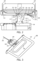
- FIG. 1 illustrates one example of a system 100 for tilting an infant-care medical device, e.g., such as a warmer 120 as shown.
- warmer 120 may comprise a frame 122, a bed 124, a base 116 having wheels 118.
- bed 124 may be disposed on top of a tilt platform 102 of system 100.
- tilt platform 102 may pivot about a tilt axis.
- System 100 may also include a support structure 106 disposed on top of the base, a first support 132 disposed between support structure 106 and tilt platform 102 having one end 130 rotatably coupled to tilt platform 102 at a pivot 110, an actuator 108 mounted to tilt platform on a first side 126 of tilt platform 102, and a damper 114, as shown in this example.
- system 100 may also include a second support 112 mounted to tilt platform 102 on a second side 128 of tilt platform 102, opposite of first side 126.
- system 100 may also include any other suitable structure.
- tilt platform 102 may be configured to support an infant within bed 124 having a thermo-regulated area provided by warmer 120.
- tilt platform 102 may form an integral part of the infant-care device, such as a bottom of bed 124.
- tilt platform 102 may form a platform structure separate from the infant-care device, e.g., a tiltable base that supports bed 124 shown.
- tilt platform 102 may be further configured to tilt about tilt axis at pivot 110.
- a tilt mechanism 134 may provide a pivot 110 to facilitate pivoting of tilt platform 102.
- tilt mechanism 134 may comprise first support 132, disposed between tilt platform 102 and support structure 106.
- First support may have one end, e.g., 130, rotatably coupled to the tilt platform and is configured to facilitate pivoting of the tilt platform about the tilt axis.
- first support 132 is mounted to the tilt platform 102 at pivot 110 as shown such that tilt platform 102 may freely pivot about tilt axis in either clockwise or counter-clockwise rotational direction.
- actuator 108 disposed on first side 126 of tilt platform 102.
- actuator 108 is operable to lock tilt platform 102 to a rotational position relative to tilt axis such that tilt platform 102 is not free to pivot about tilt axis in a locked position.
- a user of system 100 e.g., a nurse, may lock tilt platform 102 to a rotational position through actuator 108 to facilitate care for an infant placed on the bed 124 supported by tilt platform 102.
- Actuator 108 may also be configured to unlock tilt platform 102 from the locked rotational position to allow tilt platform 102 to pivot about the tilt axis. Further details about actuator 108 and its operations are described in FIGs 3-5 .
- a damper 114 is disposed between support structure 106 and tilt platform 102. As shown, damper 114 may be coupled to tilt platform 102 on first side 126, i.e. the same side as actuator 108. To facilitate a smooth tilting of the infant-care medical device, Damper 114 is configured to dampen pivoting of tilt platform 102 as tilt platform 102 pivots about tilt axis. In some embodiments in accordance with the disclosure, damper 114 may be an extension device operable to apply a bias in a rotational direction to oppose the rotational force that pivots tilt platform 102.
- damper 114 may dampen a portion of the rotational force as tilt platform 102 pivots about tilt axis. As a result, damper 114 may compress as first side 126 of tilt platform 102 is lowered. Conversely, in the case where the user rotates tilt platform 102 with the second side 128 lowered and first side 126 raised, damper 114 may provide energy stored in the damper 114 to facilitate the tilting of tilt platform 102 about tilt axis.
- a second support 112 may also be mounted to tilt platform 102 on second side 128 of tilt platform 102.
- Second support 112 may be operable to move upwardly and downwardly to facilitate pivoting of tilt platform 102.
- second support 112 may apply a bias to tilt platform 102 in a rotational directional to facilitate pivoting of tilt platform 102. For instance, a user of system 100 may rotate tilt platform 102 by pushing actuator 108 downwards such that tilt platform 102 pivots about tilt axis with second side 128 being raised and first side 126 being lowered. In that case, in response to the actuation force applied by the user, second support 112 may extend to raise second side 128 of tilt platform 102.
- a user of system 100 may rotate tilt platform 102 by lifting actuator 108 such that tilt platform 102 pivots about tilt axis with second side 128 being lowered and first side 126 being raised.
- second support 112 may move downwardly so that second side 128 of tilt platform 102 may be lowered.
- second support 112 may also be configured such that it may be locked in an extended or compressed position, e.g., through a control mechanism connected to actuator 108, such that tilt platform 102 is locked in a desired rotational position.
- a control mechanism is further described in FIGs 3-5 .
- second support 112 and damper 114 work in tandem providing a smooth tilting for an infant-care medical device.
- the damping force provided by damper 114 serves as counter-balancing to the rotational force that pivots tilt platform 102 about tilt axis.
- damper 114 may be non-lockable such that it extends and compresses freely to achieve the damping. Through damping in accordance with the disclosure, movements associated with tilting mechanism for infant-care medical device may be damped.
- second support 112 is mounted to second side 128 of tilt platform 102 and damper 114 is mounted to first side 126, in some other examples, second support 112 may be mounted to first side 126 and damper 114 may be mounted to second side 128 of tilt platform 102.
- second support 112 and damper 114 may comprise substance that generates biases when the substance is decompressed and compressed.
- substance may include, but not limited to, pneumatic agents such as gases that provide releasing and storing of energy when the substance is decompressed and compressed.
- second support 112 and damper 114 may be gas springs that releases energy when decompressed (e.g. extending) and stores energy when compressed.
- FIG. 2 illustrates another example of a system 100 for tilting an infant-care medical device. It will be described with reference to FIG. 1 .
- actuator 108 may be rigidly mounted on tilt platform 102 at a second pivot 216 of system 100 on second side of tilt platform 102, i.e. second side 128 as shown in FIG 1 .
- actuator 108 may include an actuating handle 214 that facilitates user to rotate tilt platform 102 about tilt axis, a link member 204, and a lever 228.
- actuator 108 may pivot at second pivot 216 to allow an actuation force that rotates tilt platform 102 to be applied, for example, by a user through actuating handle 214. Further details about actuator 108 are described in FIG 3 .
- second support 112 may be disposed on first side 126 of tilt platform 102, which is tiltable about tilt axis at pivot 110.
- second support 112 may comprise, a control valve 206, casing 210 and piston rod 212.
- second support 112 may be mounted to support structure 106 using one or more couples 222.
- Second support 112 may also be connected to tilt platform 102 at a third pivot 224 of system 100.
- third pivot 224 second support 112 may allow tilt platform to pivot in the same rotational direction as tilt platform 102 pivots about tilt axis at pivot 110 provided by first support 132.
- damper 114 mounted to first side 126 of tilt platform 102 at a fourth pivot 226 of system 100.
- damper 114 may also be mounted to support structure 106 by one or more couples 222. Similar to second support 112, damper 114 may also include a casing 218, and a piston rod 220. At fourth pivot 226, damper 114 may also facilitate tilt platform 102 to tilt to a rotational position.
- actuator 108 may be configured to control second support 112 through link member 204.
- second support 112 may move upwardly or downwardly to facilitate the rotating.
- a user may apply an actuation force to actuator 108 to release control valve 206 of second support 112 to release tilt platform 102 from a locked rotational position.
- second support 112 may be a gas spring.
- gases contained in a chamber of second support 112 may flow to another and result in a decrease of density of gas within the chamber. This further result in a release of energy stored in second support 112 and thereby allows piston rod 212 to extend to heighten tilt platform 102.
- damper 114 may be configured to dampen the energy released by second support.
- damper 114 may also be a gas spring in some examples.
- damper 114 may also be a gas spring in some examples.
- the pivoting of tilt platform 102 may cause the damper 114 to depress.
- the depressing of damper 114 may then compress gases within damper 114 to increase the density of the gases.
- the compressed gases within gas spring 114 stores a portion of the energy released by second support 112 and actuation force applied by the user.
- damper 114 may effectively provide a counter-balancing to the release of energy done by second support 112.
- Such counter-balancing helps dampen movements of tilt platform 102 as tilt platform 102 tilts about the tilt axis.
- first side 126 of tilt platform 102 may be lowered when a user applies an actuation force to depress control valve 206 such that second support 112 moves downwardly.
- the compression of second support 112 allows first side128 of tilt platform 102 to be lowered.
- damper 114 is extended as its control valve 206 is allowed to be released and thereby help the user exert a force to depress control valve 206.
- FIG. 3 is a diagram illustrating one example of an actuator 108 as shown in FIGS 1 and 2 . It will be described with references to FIGs 1-2 .
- actuator 108 may include an actuating handle 214, a lever 228, a slide block 306, a link member 204 and a spring 304 disposed inside a spring chamber 308.
- actuator 108 may include any other suitable structure to effect actuating and controlling an infant-care medical device in accordance with the disclosure.
- actuating handle 224 may be configured to allow an actuation force to be applied to facilitate pivoting of tilt platform 102.
- the user may apply a grip to actuating handle 214 and apply an actuation movement (e.g., pushing actuator 108 downwards for a rotational degree).
- actuating handle 204 allows a user to adjust rotational position of tilt platform 102 relative to the tilt axis.
- lever 228, as shown, may also be operatively connected to a link member 204, such as but not limited to a Bowden cable.
- lever 228 may be configured to unlock second support 112.
- lever 228, for example, may be configured to move parallel to actuating handle 214 such that pulling 228 away from slide block 306 also pulls member link 204 in the same direction and thereby moves control valve 206 of second support 112 from a closed position to a release position (i.e. releasing control valve 206) as shown in FIG. 2 .
- lever 228 may also be configured to lock second support 112.
- lever 228, for example as shown, may be configured such that releasing lever 228 from an away position relative to slide block 306 also releases member link 204 in the same direction and thereby returns control valve 206 of second support 112 from the position to a closes position (i.e. depressing control valve 206) as shown in FIG. 2 .
- slide block 306 may include a spring mechanism that helps move lever 228.
- slide block 306 comprises a spring 304, which moves inside spring chamber 308 and may form an integral part of actuator 108.
- Spring chamber 308 may be configured to restrain extension of spring 304 such that spring 304 may not extend outside of spring chamber 308.
- spring 304 may be configured to be connected to lever 228 and allows lever 228 to be released and closed as described above. As so configured, spring 304 may help overcome some friction caused by sliding of member link 204, such as a Bowden cable, connected to lever 228.
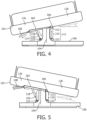
- FIG. 4 is a diagram illustrating one example to tilt an infant-care medical device in accordance with the disclosure. It will be described with references to FIGs 1-3 .
- a user may use a system 100 to tilt an infant-care medical device to a ⁇ degree relative to tilt axis.
- the user may first release and hold lever 228 of actuator 108 to pull member link 204.
- member link 204 is connected to control valve 206 of second support 112
- the pulling of control valve 206 unlocks second support 112 as described in FIG. 2 to allow second support 112 to freely move upwardly and downwardly.
- the user may apply an actuation force (e.g. pulling downwards) to actuating handle 214 until infant-care tilt platform 102 reaches that position.
- an actuation force e.g. pulling downwards
- second support 112 and damper 114 work in tandem to dampen and reduce the rotational force and movements applied by the user.
- second support 114 moves upwardly since it is unlocked by the pulling force applied by the user through actuator 108 via member link 204.
- damper 114 may compresses as shown to dampen a portion of rotational force that pivots tilt platform 102.
- the user may release lever 228 to lock second support 112 such that second support 112 is not free to move upwardly or downwardly.
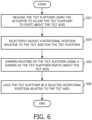
- FIG. 5 is a diagram illustrating another example to tilt an infant-care medical device in accordance with the disclosure. It will be described with references to FIGs 1-3 .
- a user may tilt an infant-care medical device to a - ⁇ degree relative to tilt axis 104, as shown in FIG. 5 .
- the user may first release and hold lever 228 of actuator 108 to pull member link 204.
- member link 204 is connected to control valve 206 of second support 112
- the pulling of control valve 206 unlocks second support 112 as described in FIG. 2 to allow second support 112 to freely move downwardly and upwardly.
- the user may apply an actuation force (e.g. lifting upwards) to actuating handle 214 until tilt platform 102 reaches that position.
- an actuation force e.g. lifting upwards
- second support 112 and damper 114 work in tandem as described above.
- second support 112 moves downwardly since it is unlocked by the pulling force applied by the user through actuator 108 via member link 204.
- damper 114 may extend as shown to help apply a portion of rotational force that pivots tilt platform 102.
- the user may release lever 228 to lock second support 112 such that second support 112 is not free to move upwardly or downwardly.
- FIG. 6 is a flow chart illustrating one example of tilting an infant-care medical device in accordance with the disclosure. It will be described with references to FIGs 1-3 .
- a user may release tilt platform 102 using actuator 108 to allow the tilt platform 102 to pivot about the tilt axis. 101.
- Actuator 108 may include a lever 228 that allows the user to unlock tilt platform 102 from the rotational position relative to tilt axis by, for example, pulling lever 228 parallel towards actuating handle 214.
- Lever 228 may be connected to a control mechanism such as member link 204.
- the control mechanism may be connected to tilt mechanism 134 at the other end opposite the end connecting to lever 228 to achieve locking and unlocking the tilt platform as described above.
- the user may selectively adjust a rotational position of tilt platform 102 relative to tilt axis.
- a user may apply an actuation force to actuator 108 to rotate tilt platform 102. For instance, the user may push actuator 108 downwards while holding actuating handle 214 as described above.
- damper 114 may dampen pivoting of tilt platform 102 as tilt platform 102 pivots about tilt axis.
- damper 114 may be a non-lockable gas spring that extends or compresses freely as tilt platform 102 pivots about tilt axis. As described above, damper 114 may provide a counter-balancing to tilt platform 102 to facilitate smooth tilting of tilt platform 102.
- the user may lock tilt platform 102 in a selected rotational position relative to the tilt axis.
- the user may release lever 228 of actuator 108 as tilt platform reaches a desired rotational position.
- the release of lever 228 may release a control mechanism such as member link 204 that is connected to tilt mechanism 134.
- the release of member link 204 in turn allows tilt platform 102 to be locked as described above.
- any reference signs placed between parentheses shall not be construed as limiting the claim.
- the word “comprising” or “including” does not exclude the presence of elements or steps other than those listed in a claim.
- several of these means may be embodied by one and the same item of hardware.
- the word “a” or “an” preceding an element does not exclude the presence of a plurality of such elements.
- any device claim enumerating several means several of these means may be embodied by one and the same item of hardware.
- the mere fact that certain elements are recited in mutually different dependent claims does not indicate that these elements cannot be used in combination.
Description
- The present disclosure pertains to a method and apparatus for tilting an infant-care medical device, and, in particular for providing a smooth tilting for the infant-care medical device.
- Infants are vulnerable to infections, and bacterial organisms, viral organisms, and other pathogenic organisms that can cause infections. At least in some cases, these can be transmitted through airborne transmission of ambient air containing contaminated particles. Incubators, baby warmers, infant-supporting devices, and/or infant-care medical devices for infants, e.g. neonates, can be used in intensive care environments or elsewhere, e.g. to maintain an environment with an appropriate temperature, air flow, humidity, sterile conditions, and/or other environmental conditions. Examples of such incubators can be found in
US4819282 ,EP1764071 and/orEP0743054 . Environments that commonly employ incubators and/or baby warmers, such as, e.g., hospitals, commonly are plagued by a wide range of pathogenic organisms. Some infants may, under certain conditions, benefit from being positioned at a tilted angle rather than on a flat surface. For example, head end elevation may prevent gastro esophageal reflux (GER) in preterm infants. Foot end elevation may benefit neonates having cardiac failure. - Accordingly, one aspect of the present disclosure relates to a system as defined by the appended claims, wherein the system tilts a tilt platform that tilts about a tilt axis, wherein the tilt platform is configured to support an infant-care medical device. The system comprises a support structure, a tilt platform mounted on the support structure, wherein the tilt platform configured to support an infant within the thermo-regulated area, the tilt platform being configured to pivot about a tilt axis, and an actuator coupled with the tilt platform, wherein the actuator is operable to lock the tilt platform in a rotational position relative to the tilt axis such that the tilt platform is not free to pivot about the tilt axis and unlock the tilt platform from the locked rotational position to allow the tilt platform to pivot about the tilt axis. The system also comprises a damper disposed between the tilt platform and the support structure, wherein the damper is coupled to the tilt platform and is configured to dampen pivoting of the tilt platform as the tilt platform pivots about the tilt axis.
- Another aspect of present disclosure relates to a method for tilting an infant-care medical device as defined by the appended claims having a thermo-regulated area using a system having a tilt platform that tilts about a tilt axis, a support structure, an actuator, a tilt mechanism, and a damper disposed between the tilt platform and support structure. The method comprises releasing the tilt platform using the actuator to allow the tilt platform to pivot about the tilt axis; selectively adjusting a rotational position of the tilt platform relative to the tilt axis; dampening pivoting of tilt platform using the damper as the tilt platform pivots about the tilt axis; and locking the tilt platform in a selected rotational position relative to the tilt axis.
- In an example, the present disclosure relates to a system for tilting an infant-care medical device having a thermo-regulated area. The system comprises support means, platform means mounted on the support structure, wherein the platform means is configured to support an infant within the thermo-regulated area, the platform means being configured to pivot about a tilt axis, and actuation means coupled with the platform means, wherein the actuation means is configured to lock the platform means in a rotational position relative to the tilt axis such that the platform means is not free to pivot about the tilt axis and unlock the platform means from the locked rotational position to allow the platform means to pivot about the tilt axis. The system also comprises a damping means disposed between the platform means and the support means, wherein the damping means is coupled to the platform means and is configured to dampen pivoting of the tilt platform as the platform means pivots about the tilt axis.
- These and other objects, features, and characteristics of the present disclosure, as well as the methods of operation and functions of the related elements of structure and the combination of parts and economies of manufacture, will become more apparent upon consideration of the following description and the appended claims with reference to the accompanying drawings, all of which form a part of this specification, wherein like reference numerals designate corresponding parts in the various figures. It is to be expressly understood, however, that the drawings are for the purpose of illustration and description only and are not intended as a definition of the limits of the disclosure. The invention is defined by the appended claims.
- The embodiments will be more readily understood in view of the following description when accompanied by the below figures and wherein like reference numerals represent like elements, wherein:
-
FIG. 1 is a diagram illustrating one example of a system for tilting an infant-care medical device; -
FIG. 2 is a diagram illustrating another example of a system for tilting an infant-care medical device; -
FIG. 3 is a diagram illustrating one example of an actuator as shown inFIG. 1 andFIG.2 ; -
FIG. 4-5 illustrates two examples of tilting an infant care medical device in accordance with the disclosure; and -
FIG.6 is a flow chart illustrating one example of tilting a system for tilting an infant-care medical device. - As used herein, the singular form of "a", "an", and "the" include plural references unless the context clearly dictates otherwise. As used herein, the statement that two or more parts or components are "coupled" shall mean that the parts are joined or operate together either directly or indirectly, i.e., through one or more intermediate parts or components, so long as a link occurs. As used herein, "directly coupled" means that two elements are directly in contact with each other. As used herein, "fixedly coupled" or "fixed" means that two components are coupled so as to move as one while maintaining a constant orientation relative to each other.
- As used herein, the word "unitary" means a component is created as a single piece or unit. That is, a component that includes pieces that are created separately and then coupled together as a unit is not a "unitary" component or body. As employed herein, the statement that two or more parts or components "engage" one another shall mean that the parts exert a force against one another either directly or through one or more intermediate parts or components. As employed herein, the term "number" shall mean one or an integer greater than one (i.e., a plurality).
- Directional phrases used herein, such as, for example and without limitation, top, bottom, left, right, upper, lower, front, back, and derivatives thereof, relate to the orientation of the elements shown in the drawings and are not limiting upon the claims unless expressly recited therein.
-
FIG. 1 illustrates one example of asystem 100 for tilting an infant-care medical device, e.g., such as a warmer 120 as shown. In this example, warmer 120 may comprise aframe 122, abed 124, abase 116 havingwheels 118. As shown in this example,bed 124 may be disposed on top of atilt platform 102 ofsystem 100. As shown,tilt platform 102 may pivot about a tilt axis.System 100 may also include asupport structure 106 disposed on top of the base, afirst support 132 disposed betweensupport structure 106 andtilt platform 102 having oneend 130 rotatably coupled totilt platform 102 at apivot 110, anactuator 108 mounted to tilt platform on afirst side 126 oftilt platform 102, and adamper 114, as shown in this example. As also shown,system 100 may also include asecond support 112 mounted totilt platform 102 on asecond side 128 oftilt platform 102, opposite offirst side 126. One of ordinary skill in the art will recognize thatsystem 100 may also include any other suitable structure. - As shown in this example,
tilt platform 102, together withsupport structure 106 andbase 116, may be configured to support an infant withinbed 124 having a thermo-regulated area provided by warmer 120. In some embodiments in accordance with the disclosure,tilt platform 102 may form an integral part of the infant-care device, such as a bottom ofbed 124. In some other embodiments in accordance with the disclosure,tilt platform 102 may form a platform structure separate from the infant-care device, e.g., a tiltable base that supportsbed 124 shown. As also shown in this example,tilt platform 102 may be further configured to tilt about tilt axis atpivot 110. - As shown in this example, a
tilt mechanism 134 may provide apivot 110 to facilitate pivoting oftilt platform 102. As also shown,tilt mechanism 134 may comprisefirst support 132, disposed betweentilt platform 102 andsupport structure 106. First support may have one end, e.g., 130, rotatably coupled to the tilt platform and is configured to facilitate pivoting of the tilt platform about the tilt axis. In this example,first support 132 is mounted to thetilt platform 102 atpivot 110 as shown such thattilt platform 102 may freely pivot about tilt axis in either clockwise or counter-clockwise rotational direction. - Still shown in this example is
actuator 108 disposed onfirst side 126 oftilt platform 102. In this example,actuator 108 is operable to locktilt platform 102 to a rotational position relative to tilt axis such thattilt platform 102 is not free to pivot about tilt axis in a locked position. For example, a user ofsystem 100, e.g., a nurse, may locktilt platform 102 to a rotational position throughactuator 108 to facilitate care for an infant placed on thebed 124 supported bytilt platform 102. Actuator 108 may also be configured to unlocktilt platform 102 from the locked rotational position to allowtilt platform 102 to pivot about the tilt axis. Further details aboutactuator 108 and its operations are described inFIGs 3-5 . - In this example, a
damper 114 is disposed betweensupport structure 106 andtilt platform 102. As shown,damper 114 may be coupled totilt platform 102 onfirst side 126, i.e. the same side asactuator 108. To facilitate a smooth tilting of the infant-care medical device, Damper 114 is configured to dampen pivoting oftilt platform 102 astilt platform 102 pivots about tilt axis. In some embodiments in accordance with the disclosure,damper 114 may be an extension device operable to apply a bias in a rotational direction to oppose the rotational force thatpivots tilt platform 102. For instance, in a use case where the user rotatestilt platform 102 with asecond side 128 of tilt platform 102 (i.e., the side opposite of first side of 126) raised andfirst side 126 lowered,damper 114 may dampen a portion of the rotational force astilt platform 102 pivots about tilt axis. As a result,damper 114 may compress asfirst side 126 oftilt platform 102 is lowered. Conversely, in the case where the user rotatestilt platform 102 with thesecond side 128 lowered andfirst side 126 raised,damper 114 may provide energy stored in thedamper 114 to facilitate the tilting oftilt platform 102 about tilt axis. - As also shown in this example, a
second support 112 may also be mounted totilt platform 102 onsecond side 128 oftilt platform 102.Second support 112 may be operable to move upwardly and downwardly to facilitate pivoting oftilt platform 102. In some examples,second support 112 may apply a bias totilt platform 102 in a rotational directional to facilitate pivoting oftilt platform 102. For instance, a user ofsystem 100 may rotatetilt platform 102 by pushingactuator 108 downwards such thattilt platform 102 pivots about tilt axis withsecond side 128 being raised andfirst side 126 being lowered. In that case, in response to the actuation force applied by the user,second support 112 may extend to raisesecond side 128 oftilt platform 102. In another use case, a user ofsystem 100 may rotatetilt platform 102 by liftingactuator 108 such thattilt platform 102 pivots about tilt axis withsecond side 128 being lowered andfirst side 126 being raised. In that case, in response to the user actuation force,second support 112 may move downwardly so thatsecond side 128 oftilt platform 102 may be lowered. In either case,second support 112 may also be configured such that it may be locked in an extended or compressed position, e.g., through a control mechanism connected toactuator 108, such thattilt platform 102 is locked in a desired rotational position. Such a control mechanism is further described inFIGs 3-5 . - As described above,
second support 112 anddamper 114 work in tandem providing a smooth tilting for an infant-care medical device. Particularly, the damping force provided bydamper 114 serves as counter-balancing to the rotational force that pivotstilt platform 102 about tilt axis. In some embodiments in accordance with the disclosure,damper 114 may be non-lockable such that it extends and compresses freely to achieve the damping. Through damping in accordance with the disclosure, movements associated with tilting mechanism for infant-care medical device may be damped. It is understood that although in this examplesecond support 112 is mounted tosecond side 128 oftilt platform 102 anddamper 114 is mounted tofirst side 126, in some other examples,second support 112 may be mounted tofirst side 126 anddamper 114 may be mounted tosecond side 128 oftilt platform 102. - In some embodiments in accordance with the disclosure, to provide smooth extension and compression,
second support 112 anddamper 114 may comprise substance that generates biases when the substance is decompressed and compressed. Such substance may include, but not limited to, pneumatic agents such as gases that provide releasing and storing of energy when the substance is decompressed and compressed. For instance,second support 112 anddamper 114 may be gas springs that releases energy when decompressed (e.g. extending) and stores energy when compressed. -
FIG. 2 illustrates another example of asystem 100 for tilting an infant-care medical device. It will be described with reference toFIG. 1 . As shown in this example,actuator 108 may be rigidly mounted ontilt platform 102 at asecond pivot 216 ofsystem 100 on second side oftilt platform 102, i.e.second side 128 as shown inFIG 1 . As shown in this example,actuator 108 may include anactuating handle 214 that facilitates user to rotatetilt platform 102 about tilt axis, alink member 204, and alever 228. As also shown,actuator 108 may pivot atsecond pivot 216 to allow an actuation force that rotatestilt platform 102 to be applied, for example, by a user throughactuating handle 214. Further details aboutactuator 108 are described inFIG 3 . - As still shown in this example,
second support 112 may be disposed onfirst side 126 oftilt platform 102, which is tiltable about tilt axis atpivot 110. In this example,second support 112 may comprise, acontrol valve 206, casing 210 andpiston rod 212. As shown,second support 112 may be mounted to supportstructure 106 using one ormore couples 222.Second support 112 may also be connected to tiltplatform 102 at athird pivot 224 ofsystem 100. Atthird pivot 224,second support 112 may allow tilt platform to pivot in the same rotational direction astilt platform 102 pivots about tilt axis atpivot 110 provided byfirst support 132. - Still shown in this example is a
damper 114 mounted tofirst side 126 oftilt platform 102 at afourth pivot 226 ofsystem 100. As in this example,damper 114 may also be mounted to supportstructure 106 by one ormore couples 222. Similar tosecond support 112,damper 114 may also include acasing 218, and apiston rod 220. Atfourth pivot 226,damper 114 may also facilitatetilt platform 102 to tilt to a rotational position. - In this example,
actuator 108 may be configured to controlsecond support 112 throughlink member 204. In the case where a user applies a rotational force to actuator 108 to rotatetilt platform 102,second support 112 may move upwardly or downwardly to facilitate the rotating. A user may apply an actuation force to actuator 108 to releasecontrol valve 206 ofsecond support 112 to releasetilt platform 102 from a locked rotational position. In some examples,second support 112 may be a gas spring. In those examples, ascontrol valve 206 is released, gases contained in a chamber ofsecond support 112 may flow to another and result in a decrease of density of gas within the chamber. This further result in a release of energy stored insecond support 112 and thereby allowspiston rod 212 to extend to heightentilt platform 102. - As
first side 126 oftilt platform 102 is heightened bysecond support 112,damper 114 may be configured to dampen the energy released by second support. Likesecond support 112,damper 114 may also be a gas spring in some examples. In those examples, asdamper 114 freely extends and compresses, the pivoting oftilt platform 102 may cause thedamper 114 to depress. The depressing ofdamper 114 may then compress gases withindamper 114 to increase the density of the gases. As a result, the compressed gases withingas spring 114 stores a portion of the energy released bysecond support 112 and actuation force applied by the user. In so compressing and storing,damper 114 may effectively provide a counter-balancing to the release of energy done bysecond support 112. Such counter-balancing helps dampen movements oftilt platform 102 astilt platform 102 tilts about the tilt axis. - Conversely, the
first side 126 oftilt platform 102 may be lowered when a user applies an actuation force to depresscontrol valve 206 such thatsecond support 112 moves downwardly. In this case, the compression ofsecond support 112 allows first side128 oftilt platform 102 to be lowered. As thefirst side 126 is lowered and thesecond side 128 heightened in this case,damper 114 is extended as itscontrol valve 206 is allowed to be released and thereby help the user exert a force to depresscontrol valve 206. -
FIG. 3 is a diagram illustrating one example of anactuator 108 as shown inFIGS 1 and2 . It will be described with references toFIGs 1-2 . As shown in this example,actuator 108 may include anactuating handle 214, alever 228, aslide block 306, alink member 204 and aspring 304 disposed inside aspring chamber 308. One of ordinary skill in the art will recognizeactuator 108 may include any other suitable structure to effect actuating and controlling an infant-care medical device in accordance with the disclosure. - As shown in this example, actuating
handle 224 may be configured to allow an actuation force to be applied to facilitate pivoting oftilt platform 102. For instance, in the case where the user desires to releasecontrol valve 206 ofsecond support 112 to extendsecond support 112 so thetilt platform 102 may pivot about the tilt axis, the user may apply a grip to actuating handle 214 and apply an actuation movement (e.g., pushingactuator 108 downwards for a rotational degree). As a result, actuatinghandle 204 allows a user to adjust rotational position oftilt platform 102 relative to the tilt axis. - In this example,
lever 228, as shown, may also be operatively connected to alink member 204, such as but not limited to a Bowden cable. As also shown,lever 228 may be configured to unlocksecond support 112. To achieve this,lever 228, for example, may be configured to move parallel to actuating handle 214 such that pulling 228 away fromslide block 306 also pullsmember link 204 in the same direction and thereby movescontrol valve 206 ofsecond support 112 from a closed position to a release position (i.e. releasing control valve 206) as shown inFIG. 2 . In this example,lever 228 may also be configured to locksecond support 112. To achieve this,lever 228, for example as shown, may be configured such that releasinglever 228 from an away position relative to slideblock 306 also releasesmember link 204 in the same direction and thereby returnscontrol valve 206 ofsecond support 112 from the position to a closes position (i.e. depressing control valve 206) as shown inFIG. 2 . - In this example,
slide block 306 may include a spring mechanism that helps movelever 228. In this example,slide block 306 comprises aspring 304, which moves insidespring chamber 308 and may form an integral part ofactuator 108.Spring chamber 308 may be configured to restrain extension ofspring 304 such thatspring 304 may not extend outside ofspring chamber 308. In this example,spring 304 may be configured to be connected to lever 228 and allowslever 228 to be released and closed as described above. As so configured,spring 304 may help overcome some friction caused by sliding ofmember link 204, such as a Bowden cable, connected to lever 228. -
FIG. 4 is a diagram illustrating one example to tilt an infant-care medical device in accordance with the disclosure. It will be described with references toFIGs 1-3 . As shown, a user may use asystem 100 to tilt an infant-care medical device to a α degree relative to tilt axis. To achieve this, the user may first release and holdlever 228 ofactuator 108 to pullmember link 204. Asmember link 204 is connected to controlvalve 206 ofsecond support 112, the pulling ofcontrol valve 206 unlockssecond support 112 as described inFIG. 2 to allowsecond support 112 to freely move upwardly and downwardly. To rotatetilt platform 102 to α degree position, while holdinglever 228, the user may apply an actuation force (e.g. pulling downwards) to actuating handle 214 until infant-care tilt platform 102 reaches that position. - During the pivoting of
tilt platform 102 about the tilt axis,second support 112 anddamper 114 work in tandem to dampen and reduce the rotational force and movements applied by the user. In this example, astilt platform 102 pivots about tilt axis counter clockwise,second support 114 moves upwardly since it is unlocked by the pulling force applied by the user throughactuator 108 viamember link 204. At the same time,damper 114 may compresses as shown to dampen a portion of rotational force that pivotstilt platform 102. Once tilt platform reaches α degree position, the user may release lever 228 to locksecond support 112 such thatsecond support 112 is not free to move upwardly or downwardly. -
FIG. 5 is a diagram illustrating another example to tilt an infant-care medical device in accordance with the disclosure. It will be described with references toFIGs 1-3 . A user may tilt an infant-care medical device to a -α degree relative to tiltaxis 104, as shown inFIG. 5 . To achieve this, the user may first release and holdlever 228 ofactuator 108 to pullmember link 204. Asmember link 204 is connected to controlvalve 206 ofsecond support 112, the pulling ofcontrol valve 206 unlockssecond support 112 as described inFIG. 2 to allowsecond support 112 to freely move downwardly and upwardly. To rotatetilt platform 102 to -α degree position, while holdinglever 228, the user may apply an actuation force (e.g. lifting upwards) to actuating handle 214 untiltilt platform 102 reaches that position. - During the pivoting of
tilt platform 102 about thetilt axis 104,second support 112 anddamper 114 work in tandem as described above. In this example, astilt platform 102 pivots about tilt axis clockwise,second support 112 moves downwardly since it is unlocked by the pulling force applied by the user throughactuator 108 viamember link 204. At the same time,damper 114 may extend as shown to help apply a portion of rotational force that pivotstilt platform 102. Once tilt platform reaches -α degree position, the user may release lever 228 to locksecond support 112 such thatsecond support 112 is not free to move upwardly or downwardly. -
FIG. 6 is a flow chart illustrating one example of tilting an infant-care medical device in accordance with the disclosure. It will be described with references toFIGs 1-3 . In operation, atblock 502, a user may releasetilt platform 102 usingactuator 108 to allow thetilt platform 102 to pivot about the tilt axis. 101. As described above,Actuator 108 may include alever 228 that allows the user to unlocktilt platform 102 from the rotational position relative to tilt axis by, for example, pullinglever 228 parallel towards actuatinghandle 214.Lever 228 may be connected to a control mechanism such asmember link 204. The control mechanism may be connected to tiltmechanism 134 at the other end opposite the end connecting to lever 228 to achieve locking and unlocking the tilt platform as described above. - At
block 504, in operation, the user may selectively adjust a rotational position oftilt platform 102 relative to tilt axis. In some embodiments, a user may apply an actuation force to actuator 108 to rotatetilt platform 102. For instance, the user may push actuator 108 downwards while holding actuating handle 214 as described above. - At
block 506, in operation, in response to the actuation force applied by the user to pivottilt platform 102,damper 114 may dampen pivoting oftilt platform 102 astilt platform 102 pivots about tilt axis. In some examples,damper 114 may be a non-lockable gas spring that extends or compresses freely astilt platform 102 pivots about tilt axis. As described above,damper 114 may provide a counter-balancing to tiltplatform 102 to facilitate smooth tilting oftilt platform 102. - At
block 508, in operation the user may locktilt platform 102 in a selected rotational position relative to the tilt axis. For example, the user may release lever 228 ofactuator 108 as tilt platform reaches a desired rotational position. The release oflever 228 may release a control mechanism such asmember link 204 that is connected to tiltmechanism 134. The release ofmember link 204 in turn allowstilt platform 102 to be locked as described above. - In the claims, any reference signs placed between parentheses shall not be construed as limiting the claim. The word "comprising" or "including" does not exclude the presence of elements or steps other than those listed in a claim. In a device claim enumerating several means, several of these means may be embodied by one and the same item of hardware. The word "a" or "an" preceding an element does not exclude the presence of a plurality of such elements. In any device claim enumerating several means, several of these means may be embodied by one and the same item of hardware. The mere fact that certain elements are recited in mutually different dependent claims does not indicate that these elements cannot be used in combination.
Claims (1)
- A system (100) for tilting an infant-care medical device having a thermo-regulated area, the system (100) comprising:a support structure (106);a tilt platform (102) mounted on the support structure (106), the tilt platform (102) configured to support an infant within the thermo-regulated area and comprising a first side (126) and a second side (128) opposite to the first side (126), the tilt platform (102) being configured to pivot about a tilt axis at pivot (110) with the first side (126) and the second side (128) being raised or lowered in opposite directions;a first support (132) disposed between the tilt platform (102) and the support structure (106), wherein the first support (132) has one end (130) rotatable coupled to the tilt platform (102) and is configured to facilitate pivoting of the tilt platform (102) about the tilt axis;a tilt mechanism (134) comprising a second support (112) and arranged to selectively adjust a rotational position of the tilt platform (102) relative to the tilt axis;an actuator (108) coupled with the tilt platform (102) and disposed in the first side (126), wherein the actuator (108) is operable to:lock the tilt platform (102) in a rotational position relative to the tilt axis such that the tilt platform (102) is not free to pivot about the tilt axis; andunlock the tilt platform (102) from the locked rotational position to allow the tilt platform (102) to pivot about the tilt axis; andwherein the second support (112) is disposed between the support structure (106) and tilt platform (102), and wherein the tilt platform (102) is rotatably coupled to the second support (112) on the second side (128) of tilt platform (102), wherein the second support (112) is operable to:move upwardly and downwardly to facilitate pivoting of the tilt platform (102) about the tilt axis; andlock in a position such that the second support (112) is not free to move upwardly or downwardly in a locked position;wherein the actuator (108) is operatively connected to the second support (112) and configured to lock and unlock the second support (112) through a link member (204) connected to second support (112);wherein the actuator (108) comprises an actuating handle (214) and a lever (228), andwherein:the actuating handle (214) is configured to allow an actuation force to be applied to facilitate pivoting of the tilt platform (102); andthe lever (228), operatively connected to the link member (204), is configured to lock and unlock the second support (112) by manipulating the link member (204),characterised in that the tilt mechanism additionally comprises a damper (114) disposed between the tilt platform (102) and the support structure (106), wherein the damper (114) is coupled to the first side (126) of the tilt platform (102) and is configured to dampen pivoting of the tilt platform (102) as the tilt platform (102) pivots about the tilt axis.
Applications Claiming Priority (2)
| Application Number | Priority Date | Filing Date | Title |
|---|---|---|---|
| US201261735596P | 2012-12-11 | 2012-12-11 | |
| PCT/IB2013/060788 WO2014091412A1 (en) | 2012-12-11 | 2013-12-11 | Method and system for tilting an infant-care medical device |
Publications (2)
| Publication Number | Publication Date |
|---|---|
| EP2931202A1 EP2931202A1 (en) | 2015-10-21 |
| EP2931202B1 true EP2931202B1 (en) | 2023-04-19 |
Family
ID=50000044
Family Applications (1)
| Application Number | Title | Priority Date | Filing Date |
|---|---|---|---|
| EP13824025.4A Active EP2931202B1 (en) | 2012-12-11 | 2013-12-11 | System for tilting an infant-care medical device |
Country Status (9)
| Country | Link |
|---|---|
| US (1) | US9801770B2 (en) |
| EP (1) | EP2931202B1 (en) |
| JP (1) | JP6306042B2 (en) |
| CN (1) | CN104853709B (en) |
| BR (1) | BR112015013249A2 (en) |
| CA (1) | CA2894582A1 (en) |
| MX (1) | MX362423B (en) |
| RU (1) | RU2655268C2 (en) |
| WO (1) | WO2014091412A1 (en) |
Families Citing this family (9)
| Publication number | Priority date | Publication date | Assignee | Title |
|---|---|---|---|---|
| WO2012110941A1 (en) * | 2011-02-14 | 2012-08-23 | Koninklijke Philips Electronics N.V. | Bed apparatus having movable heater assembly |
| US10426679B2 (en) * | 2014-08-27 | 2019-10-01 | Umano Medical Inc. | Systems for patient support surface orientation and displacement |
| US10583267B2 (en) | 2014-10-03 | 2020-03-10 | British Columbia Cancer Agency Branch | Apparatus and methods for improving health outcomes of preterm infants |
| JP6618727B2 (en) * | 2015-07-09 | 2019-12-11 | パラマウントベッド株式会社 | Bed equipment |
| JP6268149B2 (en) * | 2015-12-15 | 2018-01-24 | アトムメディカル株式会社 | An incubator having a bed with a cushioning function |
| CN105662754A (en) * | 2016-01-08 | 2016-06-15 | 深圳市科曼医疗设备有限公司 | Bed body tilting device and bed body tilting control method |
| US10702073B2 (en) * | 2017-05-12 | 2020-07-07 | Steven Paperno | Portable rocker for newborn baby or infant |
| EP3746929A1 (en) * | 2018-01-29 | 2020-12-09 | Koninklijke Philips N.V. | Securing headless devices from malicious (re-)configuration |
| JP2022525037A (en) * | 2019-03-08 | 2022-05-11 | オーリス ヘルス インコーポレイテッド | Tilt mechanism and applications for medical systems |
Family Cites Families (30)
| Publication number | Priority date | Publication date | Assignee | Title |
|---|---|---|---|---|
| US2366630A (en) * | 1942-01-22 | 1945-01-02 | Kreiselman Joseph | Bassinet organization |
| US2633842A (en) * | 1950-03-30 | 1953-04-07 | Higgs George William | Infant incubator |
| US2855921A (en) * | 1957-06-05 | 1958-10-14 | Air Shields | Gas operated drive for rocking bed |
| NL292956A (en) * | 1962-05-18 | |||
| US3858570A (en) * | 1972-06-12 | 1975-01-07 | Puritan Bennett Corp | Comprehensive infant care system |
| US4006499A (en) * | 1975-07-21 | 1977-02-08 | Young Claude A | Hospital bed |
| US4628553A (en) * | 1985-03-25 | 1986-12-16 | The Boc Group, Inc. | Infant bed hydraulic tilt mechanism |
| IL75215A (en) * | 1985-05-16 | 1992-07-15 | Israel Atomic Energy Comm | Infant incubator |
| US4819282A (en) | 1987-12-07 | 1989-04-11 | Med-Ex Diagnostics Of Canada Inc. | Tilting mechanism for use with infant bassinette |
| US5131333A (en) | 1990-05-15 | 1992-07-21 | Osaka Taiyu Co., Ltd. | Tiltable table |
| US6709384B1 (en) * | 1993-12-17 | 2004-03-23 | Hill-Rom Services, Inc. | Infant thermal support device |
| US5531663A (en) | 1994-11-08 | 1996-07-02 | Ohmeda Inc. | Incubator mattress tilt mechanism |
| US5624375A (en) * | 1995-04-21 | 1997-04-29 | Ohmeda Inc. | Incubator tilt mechanism |
| US5860899A (en) * | 1996-10-07 | 1999-01-19 | New Back Technologies, L.L.C. | Back manipulating apparatus |
| US6082693A (en) * | 1997-06-06 | 2000-07-04 | Fisher & Paykel Limited | Inclination adjusting linkage arrangement for a supporting surface |
| JPH11137755A (en) * | 1997-09-04 | 1999-05-25 | Tokiko Fukushima Kk | Frame tilting device |
| US6022310A (en) * | 1997-09-09 | 2000-02-08 | Hill-Rom, Inc. | Canopy adjustment mechanisms for thermal support apparatus |
| US6071228A (en) * | 1997-09-09 | 2000-06-06 | Hill-Rom, Inc. | Patient-support assembly for thermal support apparatus |
| US6013022A (en) | 1998-06-29 | 2000-01-11 | Jones; Thomas C. | Tilt mechanism for infant care apparatus |
| US6155970A (en) * | 1998-07-20 | 2000-12-05 | Datex-Ohmeda, Inc. | Rotating infant mattress |
| US6880188B1 (en) * | 1999-11-15 | 2005-04-19 | Draeger Medical Infant Care, Inc. | Infant care apparatus with movable infant support |
| DE60040233D1 (en) * | 1999-11-15 | 2008-10-23 | Draeger Medical Systems Inc | ANIMAL CARE DEVICE WITH MOVABLE CHILDREN'S LIEGE |
| US6659935B2 (en) | 2000-09-21 | 2003-12-09 | Hill-Rom Services, Inc. | Lifting apparatus for patient support surface |
| WO2002051287A2 (en) | 2000-12-22 | 2002-07-04 | Hill-Rom Services, Inc. | Infant rocking apparatus |
| ITMI20021395A1 (en) | 2002-06-25 | 2003-12-29 | Oggioni & C S R L | CONTAINER BED WITH MEANS FOR HANDLING THE NETWORK |
| CN2704352Y (en) * | 2004-05-19 | 2005-06-15 | 陈海杰 | Bed for baby curing box |
| RU74051U1 (en) * | 2007-10-05 | 2008-06-20 | Владимир Юрьевич Большаков | MECHANISM FOR LOWERING THE SIDE BACK OF A CHILD'S BED (OPTIONS) |
| WO2009073444A1 (en) * | 2007-12-04 | 2009-06-11 | Draeger Medical Systems, Inc. | Warming therapy device including variable height and tilt adjustment |
| JP5297879B2 (en) * | 2009-05-08 | 2013-09-25 | アトムメディカル株式会社 | Child care equipment |
| WO2012110941A1 (en) * | 2011-02-14 | 2012-08-23 | Koninklijke Philips Electronics N.V. | Bed apparatus having movable heater assembly |
-
2013
- 2013-12-11 WO PCT/IB2013/060788 patent/WO2014091412A1/en active Application Filing
- 2013-12-11 RU RU2015128056A patent/RU2655268C2/en not_active IP Right Cessation
- 2013-12-11 MX MX2015007228A patent/MX362423B/en active IP Right Grant
- 2013-12-11 EP EP13824025.4A patent/EP2931202B1/en active Active
- 2013-12-11 CN CN201380064754.7A patent/CN104853709B/en active Active
- 2013-12-11 US US14/442,734 patent/US9801770B2/en active Active
- 2013-12-11 BR BR112015013249A patent/BR112015013249A2/en not_active Application Discontinuation
- 2013-12-11 CA CA2894582A patent/CA2894582A1/en not_active Abandoned
- 2013-12-11 JP JP2015546144A patent/JP6306042B2/en active Active
Also Published As
| Publication number | Publication date |
|---|---|
| JP2015536751A (en) | 2015-12-24 |
| CN104853709B (en) | 2019-12-24 |
| US20150328074A1 (en) | 2015-11-19 |
| BR112015013249A2 (en) | 2017-07-11 |
| CA2894582A1 (en) | 2014-06-19 |
| JP6306042B2 (en) | 2018-04-04 |
| US9801770B2 (en) | 2017-10-31 |
| CN104853709A (en) | 2015-08-19 |
| MX362423B (en) | 2019-01-17 |
| WO2014091412A1 (en) | 2014-06-19 |
| RU2655268C2 (en) | 2018-05-24 |
| MX2015007228A (en) | 2015-10-29 |
| EP2931202A1 (en) | 2015-10-21 |
| RU2015128056A (en) | 2017-01-16 |
Similar Documents
| Publication | Publication Date | Title |
|---|---|---|
| EP2931202B1 (en) | System for tilting an infant-care medical device | |
| US10905606B2 (en) | Patient transport apparatus for transporting a patient over disturbances in floor surfaces | |
| JP5259262B2 (en) | Arm support and seating support having such an arm support | |
| US10888164B2 (en) | Office systems with shape memory materials | |
| US20150320631A1 (en) | Assistive walking device with adjustable dimensions | |
| US11253077B2 (en) | Chair with return force mechanism | |
| JP2015536751A5 (en) | ||
| JP2016155186A (en) | Gripping device and lift assisting apparatus | |
| US20200100971A1 (en) | Height adjustment delivery table | |
| WO2017009946A1 (en) | Patient care robot | |
| US20150028641A1 (en) | Moveable Seat | |
| JP6262230B2 (en) | Direct drive tilt mechanism for infant care medical devices | |
| JP6491650B2 (en) | Simple bed and lift assist mechanism for the simple bed | |
| US20150190296A1 (en) | Direct-drive tilt mechanism for infant-care medical devices | |
| JP2006061257A (en) | Moving table | |
| JP2012152381A (en) | Human body supporting device | |
| US20210378417A1 (en) | Height adjustable bassinet | |
| JP5457926B2 (en) | Grounding member jumping mechanism for welfare equipment and carry cart incorporating the same | |
| JPS601693Y2 (en) | Flexible bed | |
| JP3602464B2 (en) | Wheelchair loading device for vehicles | |
| JPH10117875A (en) | Balance lift floor chair | |
| JP2001238911A (en) | Frame for stretcher |
Legal Events
| Date | Code | Title | Description |
|---|---|---|---|
| PUAI | Public reference made under article 153(3) epc to a published international application that has entered the european phase |
Free format text: ORIGINAL CODE: 0009012 |
|
| 17P | Request for examination filed |
Effective date: 20150713 |
|
| AK | Designated contracting states |
Kind code of ref document: A1 Designated state(s): AL AT BE BG CH CY CZ DE DK EE ES FI FR GB GR HR HU IE IS IT LI LT LU LV MC MK MT NL NO PL PT RO RS SE SI SK SM TR |
|
| AX | Request for extension of the european patent |
Extension state: BA ME |
|
| DAX | Request for extension of the european patent (deleted) | ||
| STAA | Information on the status of an ep patent application or granted ep patent |
Free format text: STATUS: EXAMINATION IS IN PROGRESS |
|
| 17Q | First examination report despatched |
Effective date: 20180703 |
|
| RAP1 | Party data changed (applicant data changed or rights of an application transferred) |
Owner name: KONINKLIJKE PHILIPS N.V. |
|
| STAA | Information on the status of an ep patent application or granted ep patent |
Free format text: STATUS: EXAMINATION IS IN PROGRESS |
|
| GRAP | Despatch of communication of intention to grant a patent |
Free format text: ORIGINAL CODE: EPIDOSNIGR1 |
|
| STAA | Information on the status of an ep patent application or granted ep patent |
Free format text: STATUS: GRANT OF PATENT IS INTENDED |
|
| INTG | Intention to grant announced |
Effective date: 20221121 |
|
| GRAS | Grant fee paid |
Free format text: ORIGINAL CODE: EPIDOSNIGR3 |
|
| GRAA | (expected) grant |
Free format text: ORIGINAL CODE: 0009210 |
|
| STAA | Information on the status of an ep patent application or granted ep patent |
Free format text: STATUS: THE PATENT HAS BEEN GRANTED |
|
| AK | Designated contracting states |
Kind code of ref document: B1 Designated state(s): AL AT BE BG CH CY CZ DE DK EE ES FI FR GB GR HR HU IE IS IT LI LT LU LV MC MK MT NL NO PL PT RO RS SE SI SK SM TR |
|
| REG | Reference to a national code |
Ref country code: GB Ref legal event code: FG4D |
|
| REG | Reference to a national code |
Ref country code: CH Ref legal event code: EP |
|
| REG | Reference to a national code |
Ref country code: DE Ref legal event code: R096 Ref document number: 602013083652 Country of ref document: DE |
|
| REG | Reference to a national code |
Ref country code: IE Ref legal event code: FG4D |
|
| REG | Reference to a national code |
Ref country code: AT Ref legal event code: REF Ref document number: 1560681 Country of ref document: AT Kind code of ref document: T Effective date: 20230515 |
|
| REG | Reference to a national code |
Ref country code: LT Ref legal event code: MG9D |
|
| REG | Reference to a national code |
Ref country code: NL Ref legal event code: MP Effective date: 20230419 |
|
| REG | Reference to a national code |
Ref country code: AT Ref legal event code: MK05 Ref document number: 1560681 Country of ref document: AT Kind code of ref document: T Effective date: 20230419 |
|
| PG25 | Lapsed in a contracting state [announced via postgrant information from national office to epo] |
Ref country code: NL Free format text: LAPSE BECAUSE OF FAILURE TO SUBMIT A TRANSLATION OF THE DESCRIPTION OR TO PAY THE FEE WITHIN THE PRESCRIBED TIME-LIMIT Effective date: 20230419 |
|
| PG25 | Lapsed in a contracting state [announced via postgrant information from national office to epo] |
Ref country code: SE Free format text: LAPSE BECAUSE OF FAILURE TO SUBMIT A TRANSLATION OF THE DESCRIPTION OR TO PAY THE FEE WITHIN THE PRESCRIBED TIME-LIMIT Effective date: 20230419 Ref country code: PT Free format text: LAPSE BECAUSE OF FAILURE TO SUBMIT A TRANSLATION OF THE DESCRIPTION OR TO PAY THE FEE WITHIN THE PRESCRIBED TIME-LIMIT Effective date: 20230821 Ref country code: NO Free format text: LAPSE BECAUSE OF FAILURE TO SUBMIT A TRANSLATION OF THE DESCRIPTION OR TO PAY THE FEE WITHIN THE PRESCRIBED TIME-LIMIT Effective date: 20230719 Ref country code: ES Free format text: LAPSE BECAUSE OF FAILURE TO SUBMIT A TRANSLATION OF THE DESCRIPTION OR TO PAY THE FEE WITHIN THE PRESCRIBED TIME-LIMIT Effective date: 20230419 Ref country code: AT Free format text: LAPSE BECAUSE OF FAILURE TO SUBMIT A TRANSLATION OF THE DESCRIPTION OR TO PAY THE FEE WITHIN THE PRESCRIBED TIME-LIMIT Effective date: 20230419 |
|
| PG25 | Lapsed in a contracting state [announced via postgrant information from national office to epo] |
Ref country code: RS Free format text: LAPSE BECAUSE OF FAILURE TO SUBMIT A TRANSLATION OF THE DESCRIPTION OR TO PAY THE FEE WITHIN THE PRESCRIBED TIME-LIMIT Effective date: 20230419 Ref country code: PL Free format text: LAPSE BECAUSE OF FAILURE TO SUBMIT A TRANSLATION OF THE DESCRIPTION OR TO PAY THE FEE WITHIN THE PRESCRIBED TIME-LIMIT Effective date: 20230419 Ref country code: LV Free format text: LAPSE BECAUSE OF FAILURE TO SUBMIT A TRANSLATION OF THE DESCRIPTION OR TO PAY THE FEE WITHIN THE PRESCRIBED TIME-LIMIT Effective date: 20230419 Ref country code: LT Free format text: LAPSE BECAUSE OF FAILURE TO SUBMIT A TRANSLATION OF THE DESCRIPTION OR TO PAY THE FEE WITHIN THE PRESCRIBED TIME-LIMIT Effective date: 20230419 Ref country code: IS Free format text: LAPSE BECAUSE OF FAILURE TO SUBMIT A TRANSLATION OF THE DESCRIPTION OR TO PAY THE FEE WITHIN THE PRESCRIBED TIME-LIMIT Effective date: 20230819 Ref country code: HR Free format text: LAPSE BECAUSE OF FAILURE TO SUBMIT A TRANSLATION OF THE DESCRIPTION OR TO PAY THE FEE WITHIN THE PRESCRIBED TIME-LIMIT Effective date: 20230419 Ref country code: GR Free format text: LAPSE BECAUSE OF FAILURE TO SUBMIT A TRANSLATION OF THE DESCRIPTION OR TO PAY THE FEE WITHIN THE PRESCRIBED TIME-LIMIT Effective date: 20230720 Ref country code: AL Free format text: LAPSE BECAUSE OF FAILURE TO SUBMIT A TRANSLATION OF THE DESCRIPTION OR TO PAY THE FEE WITHIN THE PRESCRIBED TIME-LIMIT Effective date: 20230419 |
|
| PG25 | Lapsed in a contracting state [announced via postgrant information from national office to epo] |
Ref country code: FI Free format text: LAPSE BECAUSE OF FAILURE TO SUBMIT A TRANSLATION OF THE DESCRIPTION OR TO PAY THE FEE WITHIN THE PRESCRIBED TIME-LIMIT Effective date: 20230419 |
|
| PG25 | Lapsed in a contracting state [announced via postgrant information from national office to epo] |
Ref country code: SK Free format text: LAPSE BECAUSE OF FAILURE TO SUBMIT A TRANSLATION OF THE DESCRIPTION OR TO PAY THE FEE WITHIN THE PRESCRIBED TIME-LIMIT Effective date: 20230419 |
|
| REG | Reference to a national code |
Ref country code: DE Ref legal event code: R097 Ref document number: 602013083652 Country of ref document: DE |
|
| PG25 | Lapsed in a contracting state [announced via postgrant information from national office to epo] |
Ref country code: SM Free format text: LAPSE BECAUSE OF FAILURE TO SUBMIT A TRANSLATION OF THE DESCRIPTION OR TO PAY THE FEE WITHIN THE PRESCRIBED TIME-LIMIT Effective date: 20230419 Ref country code: SK Free format text: LAPSE BECAUSE OF FAILURE TO SUBMIT A TRANSLATION OF THE DESCRIPTION OR TO PAY THE FEE WITHIN THE PRESCRIBED TIME-LIMIT Effective date: 20230419 Ref country code: RO Free format text: LAPSE BECAUSE OF FAILURE TO SUBMIT A TRANSLATION OF THE DESCRIPTION OR TO PAY THE FEE WITHIN THE PRESCRIBED TIME-LIMIT Effective date: 20230419 Ref country code: EE Free format text: LAPSE BECAUSE OF FAILURE TO SUBMIT A TRANSLATION OF THE DESCRIPTION OR TO PAY THE FEE WITHIN THE PRESCRIBED TIME-LIMIT Effective date: 20230419 Ref country code: DK Free format text: LAPSE BECAUSE OF FAILURE TO SUBMIT A TRANSLATION OF THE DESCRIPTION OR TO PAY THE FEE WITHIN THE PRESCRIBED TIME-LIMIT Effective date: 20230419 Ref country code: CZ Free format text: LAPSE BECAUSE OF FAILURE TO SUBMIT A TRANSLATION OF THE DESCRIPTION OR TO PAY THE FEE WITHIN THE PRESCRIBED TIME-LIMIT Effective date: 20230419 |
|
| PLBE | No opposition filed within time limit |
Free format text: ORIGINAL CODE: 0009261 |
|
| STAA | Information on the status of an ep patent application or granted ep patent |
Free format text: STATUS: NO OPPOSITION FILED WITHIN TIME LIMIT |
|
| 26N | No opposition filed |
Effective date: 20240122 |