EP2931169B1 - Condensing implant - Google Patents
Condensing implant Download PDFInfo
- Publication number
- EP2931169B1 EP2931169B1 EP13861830.1A EP13861830A EP2931169B1 EP 2931169 B1 EP2931169 B1 EP 2931169B1 EP 13861830 A EP13861830 A EP 13861830A EP 2931169 B1 EP2931169 B1 EP 2931169B1
- Authority
- EP
- European Patent Office
- Prior art keywords
- implant
- thread profile
- apical
- burnishing
- central
- Prior art date
- Legal status (The legal status is an assumption and is not a legal conclusion. Google has not performed a legal analysis and makes no representation as to the accuracy of the status listed.)
- Active
Links
Images


Classifications
-
- A—HUMAN NECESSITIES
- A61—MEDICAL OR VETERINARY SCIENCE; HYGIENE
- A61B—DIAGNOSIS; SURGERY; IDENTIFICATION
- A61B17/00—Surgical instruments, devices or methods
- A61B17/56—Surgical instruments or methods for treatment of bones or joints; Devices specially adapted therefor
- A61B17/58—Surgical instruments or methods for treatment of bones or joints; Devices specially adapted therefor for osteosynthesis, e.g. bone plates, screws or setting implements
- A61B17/68—Internal fixation devices, including fasteners and spinal fixators, even if a part thereof projects from the skin
- A61B17/84—Fasteners therefor or fasteners being internal fixation devices
- A61B17/86—Pins or screws or threaded wires; nuts therefor
- A61B17/8625—Shanks, i.e. parts contacting bone tissue
- A61B17/863—Shanks, i.e. parts contacting bone tissue with thread interrupted or changing its form along shank, other than constant taper
-
- A—HUMAN NECESSITIES
- A61—MEDICAL OR VETERINARY SCIENCE; HYGIENE
- A61C—DENTISTRY; APPARATUS OR METHODS FOR ORAL OR DENTAL HYGIENE
- A61C3/00—Dental tools or instruments
- A61C3/02—Tooth drilling or cutting instruments; Instruments acting like a sandblast machine
-
- A—HUMAN NECESSITIES
- A61—MEDICAL OR VETERINARY SCIENCE; HYGIENE
- A61C—DENTISTRY; APPARATUS OR METHODS FOR ORAL OR DENTAL HYGIENE
- A61C8/00—Means to be fixed to the jaw-bone for consolidating natural teeth or for fixing dental prostheses thereon; Dental implants; Implanting tools
- A61C8/0018—Means to be fixed to the jaw-bone for consolidating natural teeth or for fixing dental prostheses thereon; Dental implants; Implanting tools characterised by the shape
- A61C8/0022—Self-screwing
- A61C8/0025—Self-screwing with multiple threads
-
- A—HUMAN NECESSITIES
- A61—MEDICAL OR VETERINARY SCIENCE; HYGIENE
- A61C—DENTISTRY; APPARATUS OR METHODS FOR ORAL OR DENTAL HYGIENE
- A61C8/00—Means to be fixed to the jaw-bone for consolidating natural teeth or for fixing dental prostheses thereon; Dental implants; Implanting tools
- A61C8/0048—Connecting the upper structure to the implant, e.g. bridging bars
- A61C8/005—Connecting devices for joining an upper structure with an implant member, e.g. spacers
- A61C8/006—Connecting devices for joining an upper structure with an implant member, e.g. spacers with polygonal positional means, e.g. hexagonal or octagonal
-
- A—HUMAN NECESSITIES
- A61—MEDICAL OR VETERINARY SCIENCE; HYGIENE
- A61B—DIAGNOSIS; SURGERY; IDENTIFICATION
- A61B17/00—Surgical instruments, devices or methods
- A61B17/56—Surgical instruments or methods for treatment of bones or joints; Devices specially adapted therefor
- A61B17/58—Surgical instruments or methods for treatment of bones or joints; Devices specially adapted therefor for osteosynthesis, e.g. bone plates, screws or setting implements
- A61B17/68—Internal fixation devices, including fasteners and spinal fixators, even if a part thereof projects from the skin
- A61B17/70—Spinal positioners or stabilisers, e.g. stabilisers comprising fluid filler in an implant
- A61B17/7001—Screws or hooks combined with longitudinal elements which do not contact vertebrae
-
- A—HUMAN NECESSITIES
- A61—MEDICAL OR VETERINARY SCIENCE; HYGIENE
- A61B—DIAGNOSIS; SURGERY; IDENTIFICATION
- A61B17/00—Surgical instruments, devices or methods
- A61B17/56—Surgical instruments or methods for treatment of bones or joints; Devices specially adapted therefor
- A61B17/58—Surgical instruments or methods for treatment of bones or joints; Devices specially adapted therefor for osteosynthesis, e.g. bone plates, screws or setting implements
- A61B17/68—Internal fixation devices, including fasteners and spinal fixators, even if a part thereof projects from the skin
- A61B17/84—Fasteners therefor or fasteners being internal fixation devices
- A61B17/86—Pins or screws or threaded wires; nuts therefor
- A61B17/8645—Headless screws, e.g. ligament interference screws
Definitions
- the invention relates generally to implants intended to provide anchorage in a relatively soft or fragile material for a fastener, and more particularly to bone anchorage implants having a combination of features designed to produce bone condensation concurrently with insertion.
- a dental implant also known as an endosteal implant or fixture
- an endosteal implant or fixture is a surgical device, used to replace one or more missing teeth by fusing to bone and supporting a crown, bridge of teeth, denture, facial prosthetic or to act as an orthodontic anchor.
- implants are designed as threaded, tapered implants that are not loaded immediately after setting in order that full stability may be reached over time as the surrounding bone grows into the crevices of and around the implant. Several months are typically required for bone ingrown until the implant reaches sufficient stability to be put into full service.
- orthopedic implants are used in other medial situations to replace a missing joint or bone or to support a damaged bone or to provide an anchor point for a fastener.
- orthopedic implants are pins, rods, screws and plates used to anchor fractured bones while they heal.
- Types of internal fixators include bone screws and metal plates, pins, rods, Kirschner wires and intramedullary devices such as the Kuntscher nail and interlocking nail.
- Implant stability is thus a long-felt need in the art with improvements readily embraced as a testimony to the need for continued improvement.
- WO2011/053588 describes a bone screw that attaches an implant to bone or bony tissue.
- the device includes grooves that widen toward a proximal end portion.
- a bone implant is provided of the type that is screwed into an osteotomy.
- the implant has a body with a conically tapered profile.
- the body includes an apical end and a coronal end.
- a central region of the body extends between the apical end and the coronal end.
- the apical end has an apical thread profile configured to advance the body progressively deeper into the osteotomy as the body is forcibly turned in a first rotary direction.
- the central region includes at least one longitudinally extending burnishing edge configured to apply a circumferentially sweeping compressive strain to the interior surface of the osteotomy with a burnishing action while the implant is being screwed into position.
- an implant for any type of application that is screwed into a hole comprises a body having a conically tapered profile.
- the body has an apical end and a coronal end.
- a central region of the body extends between the apical end and the coronal end.
- the apical end has an apical thread profile defined by a helical twist in a first rotary direction for advancing the body progressively deeper into the hole as the body is forcibly turned in the first rotary direction.
- the central region includes a plurality of burnishing edges each configured to apply a circumferentially sweeping compressive strain to the interior surface of the hole with a burnishing action while the implant is being screwed into position.
- a method for screwing an implant into an osteotomy. The method comprises the steps of: inserting an apical end of an implant body into the opening of an osteotomy, screwing the body progressively deeper into the osteotomy, and applying a circumferentially sweeping compressive strain to the interior surface of the osteotomy with at least one burnishing edge while concurrently with the screwing step.
- a still further advantage provided by the one or more burnishing edges is its ability to strengthen the surrounding material or bone through the introduction of stresses between the material's yield point and its ultimate tensile strength, thereby provoking strain hardening, which occurs because of dislocation movements and dislocation generation within the crystal structure of the material.
- Another benefit of this implant with burnishing edges when used in bone applications is its ability to activate natural bone re-generation.
- a permanent change in shape is believed to be associated with micro-cracks that allow energy release, a natural defense mechanism of living bone. This energy release naturally activates bone regeneration for successful long-term implant stability.
- an implant according to this invention is capable of reaching sufficient implant stability at the time of initial placement. Furthermore, because of its unique ability to promote bone regeneration, long-term implant stability is both enhanced and accelerated.
- the unique burnishing attributes of this invention are compatible with many of the prior art variations in thread shape, surface texture and/or special coatings.
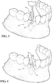
- Figures 1-4 show the example of a dental implant, in which preparation of an osteotomy is required to receive a bone implant ( Figure 4 ).
- this invention is not limited to dental applications, but may be applied across a wide spectrum of orthopedic applications.
- the invention is not even limited to bone or orthopedic applications, but may be used to prepare holes in metal foam and other cellular materials for industrial and commercial applications, to name but a few.
- dental applications represent a convenient example, and so a significant portion of the following description will make use of the dental context for chiefly illustrative purposes only.
- an edentulous (without teeth) jaw site 30 is shown that needs expanded and prepared as an osteotomy 32 ( Figure 2 ) in order to receive an implant, generally shown at 34 in Figure 4 .
- the series of steps include first boring a pilot hole or dimple into the recipient bone and then expanding the osteotomy to final size and depth using any suitable drilling or osteotome technique.
- One such technique comprises the use of progressively wider rotary osteotomes, generally indicated at 36, as shown in Figure 3 .
- the procedure of forming an osteotomy using progressively wider rotary osteotomes is described, generally, in US 2013/0004918 published January 3, 2013 to Huwais .
- the implant 34 may be re-configured as a bone screw or other bone fixation element as may be used for example in other orthopedic applications.
- the implant 34 is shown in one embodiment comprising a truncated body formed with a conically tapered outer profile.
- the body has an apical end 40 and a coronal end 42.
- apical and coronal are selected primarily for their dental association.
- “Apical” means a direction toward the root tip(s) of a tooth; and “coronal” means a direction toward the crown of a tooth. Applicant's use of these terms and perhaps others in this document, however, must not be construed narrowly as to limit the application of the implant 34 to the dental fields of use, or even to the medical fields of use.
- the apical end 40 forms the leading end of the implant 34 and in use is inserted first into the prepared osteotomy 32.
- a central region 44 of the body extends between the apical end 40 and the coronal end 42.
- the longitudinal lengths of the apical end 40, coronal end 42 and central region 44 can vary relative to the entire longitudinal length of the body.
- the apical end 40 is shown extending approximately 1/5 the entire longitudinal length of the body.
- the coronal end 42 also extends approximately 1/5 the entire longitudinal length of the body.
- the central region 44 in this example extends about 3/5 the entire longitudinal length of the body.
- the apical end 40 could be changed to approximately 1 ⁇ 4 the length of the body; the coronal end 42 shortened to 1/8 the overall length, and the central region 44 made approximately 5/8 the overall body length.
- the apical end 40 is approximately 1/3 the length of the body; the central region 44 occupies the remaining 2/3 overall body length, and the length of the coronal end 42 made effectively negligible.
- the outer (i.e., radial) dimensions of the sections 40-44 form a generally conical taper that enlarges toward the coronal end 42.
- Tapers in the range of 1°-5° are considered generally suitable for dental applications, with 2°36' considered more or less preferred. For non-dental orthopedic applications, a somewhat larger taper range may be desired. For non-medical applications, still larger taper ranges may be considered.
- a conical, root-shaped geometry is believed to support superior primary stability and loading protocols.
- the extreme apex of the apical end 40 may be domed to help prevent over-insertion and/or to otherwise contribute to safer implant placement.
- the apical end 40 is formed with an apical thread profile 46.
- the apical thread profile 46 has a right-hand twist for advancing the implant 34 progressively deeper into the osteotomy 32 as the body is forcibly turned in a clockwise direction. That is, the apical thread profile 46 forms a lead screw feature that simultaneously cuts and forges downward path in the walls of the osteotomy 32.
- the apical thread profile 46 has an apical pitch and an apical lead as these terms are generally understood in the context of screw threads. That is, lead is the distance along the longitudinal axis of the implant 34 that is covered by one complete rotation (360°) of the implant 34. Pitch is the distance from the crest of one thread to the next.
- the apical thread profile 46 is designed as a single-start thread form, the apical lead and the apical pitch will be the same length.
- the apical thread profile 46 is formed as a two-start (or double-start) thread pattern, meaning that there are two non-intersecting ridges of thread profile 46 wrapped around the implant body. Each time that the implant 34 rotates one turn (360°), it advances axially by the width of two ridges, i.e., by the apical lead distance.
- the apical thread profile has an apical lead which is equal to twice its apical pitch, and which increases the speed at which the implant 34 is advanced into the osteotomy 32.
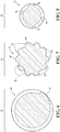
- Figure 8 is a cross-section (taken from Figure 5 ) through the apical end 40.
- the two-start thread pattern is clearly shown, along with the V-thread shape of the apical thread pattern which is one of several suitable alternative shapes.
- the apical end 40 is preferably designed so as to make the implant 34 self-tapping.
- Self-tapping indicates the ability for the implant 34 to advance when turned, while creating its own thread. This self-tapping ability may be facilitated by at least one self-tapping cutting edge 48.
- the self-tapping cutting edges 48 may be created by grinding a gap in the continuity of the threads in the apical thread profile 46.
- These self-tapping cutting edges 48 help cut complementary threads in the surrounding walls of the osteotomy 32 as the implant 34 is screwed in the clockwise direction.
- the cutting edges 48 may be considered to slice into the bone material, leaving a clean path for the screw threads to follow.
- the apical end 40 is formed with a pair of diametrically opposed self-tapping cutting edges 48, each formed by a cut disposed in a generally helical pattern extending longitudinally toward the central region 44.
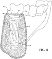
- the coronal end 42 comprises a platform 50 disposed centrally as a distal-most feature. In use, the platform 50 remains exposed once the implant 34 is fully seated in the osteotomy 32, as perhaps best shown in Figures 4 and 11 .
- An internal connect 52 extends through the platform 50 down into the body of the implant 34.
- the internal connect 52 is a standard, cavity-like feature found in many prior art implant designs, and is composed of a counter bore section directly adjacent the platform 50 which extends down to an internally threaded section that is adapted to receive the threaded post of the abutment member 38 ( Figure 4 ).
- the depth of the internal connect 52 may vary, but in some dental applications typically extends to about the mid-length point of the implant 34.
- the external features of the coronal end 42 may be formed in any number of different shapes.
- the coronal end 42 is shown including an optional corking element 54.
- the corking element 54 is designed to improve bone-to-implant contact at the crestal zone, and to help reduce, if not eliminate, instances of volcanoing or mushrooming in the bone material surrounding the osteotomy 32.
- the corking element 54 thus enables the installed coronal end 42 to sit neatly at or near the surface of the bone, thus yielding a better installation.
- the corking element 54 is mentioned as optional in that one may envision an implant 34 in which no such corking feature is incorporated into the design but which enjoys other attributes and advantages of this invention.
- the corking element 54 can be formed in a variety of ways to achieve similar - although perhaps somewhat varied - results.
- the corking element 54 includes a coronal thread profile having a right-hand twist.
- the coronal thread profile is a one-start thread pattern having a pitch that is generally equal to the apical pitch.
- the coronal lead will be only 1 ⁇ 2 the length of the apical lead. Or said another way, the coronal lead is equal to the coronal pitch.
- the coronal thread profile may be configured with a buttress shape.
- the buttress thread form is designed to handle extremely high axial thrust in one direction.
- the load-bearing thread face is perpendicular to the longitudinal axis or at a slight slant (usually no greater than 7°).
- the other face is slanted at 45°.
- the coronal thread profile engages the inner wall of the osteotomy and begins displacing bone material in a downward (apical) wiping direction.
- the coronal thread profile will be pulled by apical threads into the osteotomy at twice the rate at which they would otherwise tend to advance with clock-wise rotation. This action causes the helical crest of the coronal thread profile to pull or scrape the bone material, including any bone material that may have already begun to mushroom up around the edges of the osteotomy 32, down into the osteotomy 32 resulting in a smoother, less disrupted surface around the osteotomy 32.
- the coronal thread pattern may take many different shapes and forms.
- the central region 44 is characterized by one or more, and preferably a plurality of, troughlike flutes disposed about the body. As perhaps best illustrated by the cross-section of Figure 7 , ten flutes are shown in this example.
- the flutes may be equally circumferentially arranged about the body to help maintain stability during insertion.
- the flutes could be straight axial, in the preferred embodiment the flutes having a long-lead helical twist in a left-hand direction. That is to say, the flutes preferably do not have a right-hand helical twist about said body.
- Each flute is defined between a leading face 56 and an opposite trailing face 58.
- a land 60 is formed between every two adjacent flutes. As perhaps best shown in the enlarged Figure 9 , each land 60 joins or spans the trailing face 58 of one the flute and a leading face 56 of an adjacent the flute to form a ridge-like feature.
- a burnishing edge 62 At the intersection of each land 60 and the respective trailing face 58 is a burnishing edge 62.
- the burnishing edge 62 may be substantially margin-less, meaning that the entire portion of each land 60 falls away behind the burnishing edge 62 to provide complete clearance during rotation. In prior art drills for boring holes, for example, margins are commonly incorporated behind the cutting edges to stabilize the drill in the hole and maintain the desired drill diameter.
- the land 60 tilts into the rotational direction and serves as a ramp or wedge leading the burnishing edge so that bone material is not cut from the inner wall of the osteotomy 32.
- the burnishing edge 62 therefore, is positioned in a non-cutting direction, meaning that its associated land 60 engages the wall of the osteotomy 32 before the burnishing edge 62.
- the primary taper clearance angle i.e., the angle between a tangent of the burnishing edge 62 and each land 60 as shown in Figure 9 , may fall anywhere between about 1° and 30° depending upon the application.
- the burnishing edges 62 are shown extending generally the full distance between the apical thread profile 46 and the coronal thread profile, i.e., corking element 54. Like the intervening flutes, the burnishing edges 62 also preferably have a left-hand helical twist, although straight axial configurations are also possible. Long leads, on the order of 1-to-3 times the overall length of the implant body, are contemplated for the lay of the burnishing edges 62.
- the radial measure of each burnishing edge 62 i.e., the distance from a central axis of the implant body to the arc of the burnishing edge 62, is a function of the implant 34 taper.
- a substantially aligned conical taper meets the outer crests of the apical thread profile 46 and also the burnishing edges 62 and also the outer crests of the coronal thread profile.
- the radial measure of each burnishing edge 62 may be slightly inset from the conical taper passing through the outer crests of the apical thread profile 46 and coronal thread profile.
- the radial measure of each burnishing edge 62 may stand slightly proud of the conical taper passing through the outer crests of the apical thread profile 46 and coronal thread profile.
- an osteotomy 32 is prepared to receive the implant 34 when its opening at the surface of the bone has a diameter that is approximately as large as the root diameter of the extreme apex of the apical end 40.
- the implant 34 is initially screwed into an osteotomy 32, its apical thread profile 46 immediately bites into the inner surface of the bone and cuts a downwardly spiraling path to quickly draw the remaining body of the implant 34 toward full seated depth.
- the burnishing edges 62 enter the osteotomy 32, they begin to apply a circumferentially sweeping compressive strain to the interior surface of the osteotomy 32 with a burnishing action.
- Downward pressure applied by the advancing apical thread profile 46 keeps the burnishing edges 62 in contact with the bone surface of the osteotomy 32 to maintain pressure on the compression wave. This is aided by the taper interface of the osteotomy 32 and implant 34 to create lateral pressure (i.e., in the intended radial direction of expansion).
- each burnishing edge 62 drag across the bone, the forces on each burnishing edge 62 can be decomposed into two component forces: one normal to the bone's surface, pressing it outwardly, and the other tangential, dragging it along the inner surface of the osteotomy 32. It may be noted as well that due to the left-hand helical twist, the burnishing edges 62 will also generate a slight opposing axial reaction force when concurrently forcibly advanced into the osteotomy 32. This opposing axial reaction force works against the axial advancing direction of the implant 34 insertion by applying force in a direction that urges - but is unable due to the overwhelming grip of the apical thread profile 46 - to push the implant 34 out of the osteotomy 32.
- the burnishing edges 62 slide along the bone.
- the normal (i.e., radial) forces along the burnishing edges 62 will deform the softer bone material.
- the stresses in the bone's surface will exceed its yield strength, allowing the burnishing edges 62 to plow through the surface and create a trough behind it.
- the plowing action of the burnishing edges 62 thus progressively enlarges the osteotomy 32.
- this implant 34 with burnishing edges 62 Another benefit of this implant 34 with burnishing edges 62 is observed by its ability to condense and densify the surrounding bone walls of the osteotomy, thereby still further enhancing initial implant stability.
- a still further advantage of this implant 34 with burnishing edges 62 is its ability to strengthen the bone fabric. When bone (or wood or foam, etc.) is subjected to stress in the region between its yield point and its ultimate tensile strength, the material experiences strain hardening. Strain hardening, also known as work hardening or cold working, is the strengthening of a ductile material by plastic deformation. This strengthening occurs because of dislocation movements and dislocation generation within the crystal structure of the material. And yet another benefit of this implant 34 with burnishing edges 62 is its ability to activate natural bone re-generation through mechano-biology bone healing, where generated energy activates faster bone healing.
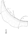
- Figure 14 is a cross-section through an osteotomy after an exemplary prior art threaded-body implant has been fully inserted therein. Impressions in the bone form a more-or-less exact negative space representation around the implant. Very little space around the implant is available for bone ingrowth, such that the same cross-section taken 1-day will look essentially the same. And similarly a cross-section taken 2-4 weeks after insertion will look essentially the same as well.
- Figure 15A represents a cross-section through an osteotomy 32 immediately after the implant 34 of this invention has been fully seated therein. Its distinctive impression in the bone is unmistakable, particularly in the relatively smooth-walled surface formed by the sweeping rotary action of the burnishing edges 62.
- Figure 15B is a cross-section as in Figure 15A showing the impression left by the same implant 34 approximately 1-day after placement. In this view, the beginnings of bone swelling and in-growth into crevices between the lands 60 and crestal thread forms of the corking element 54 are evident. Bone swelling around the central region 44 of the implant 34 effectively self-locks the implant 34 within the osteotomy 32 even at this very early stage of placement thus making even a little loosening of the implant 34 virtually impossible.
- Figure 15C shows the impression left by the same implant 34 approximately 2-4 weeks after insertion. In normal, healthy bone, nearly complete bone in-growth into the crevices of the implant 34 will occur. The implant 34 is fully mechanically locked in the bone at this stage; healing is effectively complete.
- Figures 16 and 17 show a first alternative embodiment of the present invention.
- the implant 134 is shown having a generally similar truncated body formed with a conically tapered outer profile.
- the body has an apical end 140 and a coronal end 142 and a central region 144.
- An apical thread profile 146 is characterized by an aggressive, self-tapping V-shaped two-start design, whereas a corking element 154 is included in the form of a coronal thread profile having a one-start thread pattern in a buttress style.
- a plurality of burnishing edges 162 extend with a left-hand helical twist along the central region 144.
- a central thread profile 164 that intersects the burnishing edges 162.
- the central thread profile 164 is shown in these views as a continuation of the buttress style coronal thread profile of the corking element 154.
- the combined coronal thread profile and central thread profile 164 extend, generally uninterrupted, from the coronal end 142 to the apical thread profile 146 but without overlapping the apical thread profile 146.
- the central thread profile 164 also has a right-hand twist, and a central lead which is equal to its central pitch which is also generally equal to the coronal pitch.
- the conically tapered outer profile of the implant 134 is defined by the crests, i.e., outermost helical ridges, of the apical thread profile 146 and the central thread profile 164 and the coronal thread profile. That is, in this embodiment the crests of the coronal, central and apical thread profiles are generally aligned along a conical taper that defines the overall conical taper of the implant 134. As perhaps best shown in Figure 17 , the radial measure of each burnishing edge 162 is slightly inset from the conical taper established by the outer crest of the central thread profile 164.
- the central thread profile 164 stands slightly proud of the burnishing edges so that, in use, the above-described corking action is performed by the central thread profile 164 as well as the coronal thread profile.
- the lead of the apical thread profile 146 remains approximately twice that of the lead of the integrated coronal and central 164 thread profiles so the latter thread profiles are pulled into an osteotomy at twice the rate at which they would otherwise tend to advance with clock-wise rotation of the implant 134.
- This fast-pulling action causes the helical crest of the coronal and central 164 thread profiles to displace bone material in a downward (apical) wiping direction.
- the burnishing edges 162 apply a circumferentially sweeping compressive strain to the interior surface of the osteotomy with the above-described burnishing action.
- the burnishing edges 162 wipe and rub against the bone with a progressively greater effect, interrupted at regular intervals by the central thread profile 164, as the central thread profile 164 concurrently displaces bone material in a downward wiping direction.
- the burnishing edges 162 are formed with a left-hand helical twist as shown in Figure 16 , i.e., as opposed to a straight axial (infinite lead) shape, a slight opposing axial reaction force will be generated by the burnishing edges 162 dragging across the bone surface.
- reaction force components normal, tangential and axial cooperate to stress the bone material beyond its yield strength, allowing the burnishing edges 162 to plow through the surface and progressively enlarge the osteotomy while concurrently accumulating stresses in the bone.
- reaction force components normal, tangential and axial
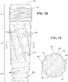
- FIGS 18 and 19 show a second alternative embodiment of the present invention.
- the implant 234 is shown having a generally similar truncated body formed with a conically tapered outer profile.
- the body has an apical end 240 and a coronal end 242 and a central region 244.
- the apical thread profile 246 is again characterized by an aggressive, self-tapping V-shaped two-start design, whereas a corking element 254 is included in the form of micro-grooves having a stacked-annular (i.e., non-threaded) pattern.
- a plurality of burnishing edges 262 extend with a left-hand helical twist along the central region 244.
- a central thread profile 264 intersects the burnishing edges 262.
- the central thread profile 264 is shown in this example as a partial continuation of the apical thread profile 246. More specifically, the apical thread profile 246 remains a two-start formation, but only one of its two thread wraps are continued into the central region 244 as the central thread profile 264.
- the one shared thread profile extends from the apical end 240 into the central region 244 generally uninterrupted.
- the central thread profile 264 also has a right-hand twist, and a central lead which is equal to its central pitch but double that of the apical pitch formed by a two-start thread wrap. Said another way, the central lead is generally equal to the apical lead, but the central pitch is twice that of the apical pitch.
- the conically tapered outer profile of the implant 234 is defined by the crests of the apical thread profile 246 and the burnishing edges 262 and the micro-grooves of the corking element 254. That is, in this embodiment the crests of the apical thread profiles 246 and the burnishing edges 264 and the crests of the micro-grooves are generally aligned along a conical taper that defines the overall conical taper of the implant 234. As perhaps best shown in Figure 19 , the radial measure of each burnishing edge 262 is slightly outset from the outer crest of the central thread profile 264.
- the burnishing edges 262 stand slightly proud of the central thread profile 264 so that, in use, the burnishing edges 262 apply a circumferentially sweeping compressive strain to the interior surface of the osteotomy with the above-described burnishing action, interrupted at intervals by the central thread profile 264.
- the above-described corking action is performed by the micro-grooves of the coronal corking element 254.
- the lead of the apical thread profile 146 is equal or generally equal to the lead of the integrated central thread profile 264 so the latter thread profile follows a track cut by the apical thread profile 246 as the implant 234 is pulled into an osteotomy with clock-wise rotation.
- the central thread profile 264 helps the apical thread profile 246 to advance the implant 234 deeper into the osteotomy.
- the burnishing edges 262 wipe and rub against the bone with a progressively greater effect akin the preceding examples.
- the corking element 254 in the form of micro-grooves provides the aforementioned corking function for the implant 234 during its final approach to full seating depth.
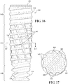
- Figure 20 shows a third alternative embodiment of the present invention.
- features of the implant corresponding to those described in the preceding example are identified with like reference numerals but with a 3-prefix rather than a 2-prefix.
- Figure 20 depicts the implant 334 in quarter-section so that the internal connect 352 is clearly visible.
- This third alternative embodiment again shows an implant 334 having a generally similar truncated body formed with a conically tapered outer profile.
- the body has an apical end 340 and a coronal end 342 and a central region 344.
- the apical thread profile 346 in this embodiment is shown with an aggressive, self-tapping square-shaped, semi-buttress two-start design.
- the corking element 354 is shown here as micro-threads.
- a plurality of burnishing edges 362 extend with a left-hand helical twist along the central region 344.
- a central thread profile 364 intersects the burnishing edges 362.
- the central thread profile 364 is a natural continuation from the apical thread profile 346.
- both of the thread wraps from the two-start apical thread profile 246 are continued, uninterrupted, through the central region 344. That is to say, the apical thread profile 346 remains a two-start formation throughout the central region 344.
- the central thread profile 364 also has a right-hand twist, and a central lead which is equal to two-times its central pitch.
- the central lead is generally equal to the apical lead.
- the conically tapered outer profile of the implant 334 is defined by the crests of the apical/central thread profiles 346, 364 and the burnishing edges 362 and the micro-threads of the corking element 354.
- the radial measure of each burnishing edge 362 is generally equal to the outer crest of the central thread profile 364. As such, the burnishing edges 362 meet at the crests of the central thread profiles 364.
- the burnishing edges 362 apply a circumferentially sweeping compressive strain to the interior surface of the osteotomy with the above-described burnishing action and are interrupted at regular times in the rotation by the central thread profile 364.
- the above-described corking action is performed by the micro-threads of the coronal corking element 354.
- the integrated central thread profile 364 follows a track cut by the apical thread profile 346 as the implant 334 drives itself into an osteotomy with clock-wise rotation, and therefore contributes to pulling the implant 334 deeper into the osteotomy.
- the burnishing edges 362 wipe and rub against the bone with a progressively greater effect as previously described.
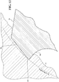
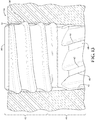
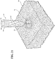
- Figures 21-22 are intended to illustrate, for the benefit of the skilled artisan, that the principles of this invention are not limited to dental applications, but may be readily extended to any bone preparation site within the human (or animal) body with suitable adjustments in scale and/or configuration. Regions shown circled in the human skeleton of Figure 21 represent a few of potentially many areas that are likely to benefit from application of the teachings of this present invention. Initial indications reveal that applications in the vertebrae (Figure 22) are prime candidates for the burnishing implant and techniques of this invention due to its potential for universally applicable increases in implant primary stability and inherent similarity to prior art implant placement techniques.
- the principles of this invention are not limited to bone as the host material.
- the burnishing implant 34 of this invention may be configured to establish an anchor in almost any type of cellular material or non-cellular material that has suitable elastic response characteristics as in the bone example given above so that when the implant 34 reaches full depth and stops rotating, accumulated stresses in the surrounding material begin to fill into the flutes and around the burnishing edges 62 more-or-less like that illustrated in Figure 12 .
- This elastic and/or healing response of the surrounding material self-locks the implant 34 in position so that it cannot be unscrewed thereby providing the implant 34 with high initial stability.
- the implant 34 may be used as an anchor in wood - both dried and green.
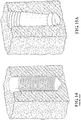
- a section of metal foam 70 may be of the type used extensively in aerospace, heat shielding and other critical applications.
- the foam metal 70 is shown including a hole 72 formed by burnishing according to the methods described above or by simple drilling. If the hole 72 is formed by burnishing according to the methods described, the resulting hole 72 is better prepared to receive the implant 34 because its inner walls have been densified by the compressive displacement and/or auto-grafting effects of that specialized technique.
- the Applicant further contemplates application of the implant 34 to civil engineering scenarios including anchors in earthen holes in soft, loose soils and muck, etc. Indeed many other applications may also present due to the unique burnishing qualities of the implant 34.
Landscapes
- Health & Medical Sciences (AREA)
- Orthopedic Medicine & Surgery (AREA)
- Life Sciences & Earth Sciences (AREA)
- Animal Behavior & Ethology (AREA)
- General Health & Medical Sciences (AREA)
- Public Health (AREA)
- Veterinary Medicine (AREA)
- Surgery (AREA)
- Oral & Maxillofacial Surgery (AREA)
- Dentistry (AREA)
- Epidemiology (AREA)
- Neurology (AREA)
- Nuclear Medicine, Radiotherapy & Molecular Imaging (AREA)
- Engineering & Computer Science (AREA)
- Biomedical Technology (AREA)
- Heart & Thoracic Surgery (AREA)
- Medical Informatics (AREA)
- Molecular Biology (AREA)
- Prostheses (AREA)
- Dental Prosthetics (AREA)
- Surgical Instruments (AREA)
- Dental Tools And Instruments Or Auxiliary Dental Instruments (AREA)
Applications Claiming Priority (2)
| Application Number | Priority Date | Filing Date | Title |
|---|---|---|---|
| US201261735558P | 2012-12-11 | 2012-12-11 | |
| PCT/US2013/074384 WO2014093487A1 (en) | 2012-12-11 | 2013-12-11 | Condensing implant |
Publications (3)
| Publication Number | Publication Date |
|---|---|
| EP2931169A1 EP2931169A1 (en) | 2015-10-21 |
| EP2931169A4 EP2931169A4 (en) | 2016-11-16 |
| EP2931169B1 true EP2931169B1 (en) | 2018-07-18 |
Family
ID=50934922
Family Applications (1)
| Application Number | Title | Priority Date | Filing Date |
|---|---|---|---|
| EP13861830.1A Active EP2931169B1 (en) | 2012-12-11 | 2013-12-11 | Condensing implant |
Country Status (13)
| Country | Link |
|---|---|
| US (1) | US9918764B2 (enExample) |
| EP (1) | EP2931169B1 (enExample) |
| JP (1) | JP6301949B2 (enExample) |
| KR (2) | KR20150092238A (enExample) |
| CN (1) | CN105120792B (enExample) |
| AU (1) | AU2013359342B2 (enExample) |
| BR (1) | BR112015012009B1 (enExample) |
| CA (1) | CA2894651C (enExample) |
| DK (1) | DK2931169T3 (enExample) |
| ES (1) | ES2687858T3 (enExample) |
| IL (1) | IL239190B (enExample) |
| WO (1) | WO2014093487A1 (enExample) |
| ZA (1) | ZA201504893B (enExample) |
Cited By (1)
| Publication number | Priority date | Publication date | Assignee | Title |
|---|---|---|---|---|
| US10912595B2 (en) | 2016-02-07 | 2021-02-09 | Huwais IP Holding LLC | Anchor screw with condensing attributes |
Families Citing this family (14)
| Publication number | Priority date | Publication date | Assignee | Title |
|---|---|---|---|---|
| US10039621B2 (en) | 2011-03-23 | 2018-08-07 | Huwais IP Holding LLC | Autografting osteotome |
| US9028253B2 (en) | 2011-03-23 | 2015-05-12 | Huwais IP Holding LLC | Fluted osteotome and surgical method for use |
| DK2931169T3 (en) | 2012-12-11 | 2018-10-08 | Huwais IP Holding LLC | CONDENSED RING IMPLANT |
| JP2017086842A (ja) * | 2015-11-16 | 2017-05-25 | 慶孝 大友 | 左回りの螺旋回転形状のねじ切りインプラント。 |
| DE202017007277U1 (de) | 2016-01-14 | 2020-10-06 | Huwais Lp Holding Llc | Autotransplantationswerkzeug mit verbessertem Nutprofil und Verwendungsmethoden |
| US10492803B2 (en) * | 2016-09-22 | 2019-12-03 | Globus Medical, Inc. | Systems and methods for intramedullary nail implantation |
| AU2017440984B2 (en) * | 2017-12-06 | 2020-02-27 | Stryker European Operations Holdings Llc | Orthopedic locking screw |
| EP3501457A1 (en) * | 2017-12-20 | 2019-06-26 | Materialise N.V. | Flexible porous implant fixation system |
| ES2971957T3 (es) * | 2018-10-22 | 2024-06-10 | Huwais IP Holding LLC | Anclaje con cámaras de cicatrización |
| AU2019377457B2 (en) | 2018-11-06 | 2025-04-03 | Huwais IP Holding LLC | Autografting tool for deep reach applications |
| KR102119968B1 (ko) * | 2018-11-08 | 2020-06-05 | 김근일 | 안정적인 고정력을 가지는 치과 임플란트 유닛 |
| US11266874B2 (en) * | 2019-05-01 | 2022-03-08 | Michael Spink | Jaw range of motion device |
| KR102304707B1 (ko) * | 2019-07-30 | 2021-09-28 | (주)해냄 | 이중 스파이럴 구조의 임플란트 시술용 콘덴싱 스크류 |
| WO2025238539A1 (en) * | 2024-05-15 | 2025-11-20 | Simple Implants Ltd | Dental implant |
Family Cites Families (52)
| Publication number | Priority date | Publication date | Assignee | Title |
|---|---|---|---|---|
| US2489179A (en) | 1946-02-26 | 1949-11-22 | Frederick F Hartman | Wheel |
| SE9102451L (sv) | 1991-08-27 | 1992-11-16 | Nobelpharma Ab | Skruvformat faestelement av titan foer permanent foerankring i benvaevnad. |
| SE9301407D0 (sv) * | 1993-04-27 | 1993-04-27 | Medevelop Ab | Foer implantation i vaevnad avsett foerankringsorgan foer uppbaerande av proteser, artificiella ledkomponenter eller dylikt |
| US6149432A (en) | 1993-12-27 | 2000-11-21 | Biolok International, Inc. | Buttress thread dental implant |
| US5816812A (en) * | 1994-07-22 | 1998-10-06 | Osteomed Corporation | Dental implant fixture |
| US5489179A (en) | 1994-08-19 | 1996-02-06 | Illinois Tool Works Inc. | Fastener and building assembly comprising workpiece, substrate, and fastener |
| US5536127A (en) * | 1994-10-13 | 1996-07-16 | Pennig; Dietmar | Headed screw construction for use in fixing the position of an intramedullary nail |
| CN2232727Y (zh) | 1995-09-15 | 1996-08-14 | 中国人民解放军总后勤部卫生部药品仪器检验所 | 便携式颅骨钻 |
| SE9700300D0 (sv) | 1997-01-31 | 1997-01-31 | Astra Ab | Reamer |
| US5961329A (en) | 1997-07-02 | 1999-10-05 | Stucki-Mccormick; Suzanne U. | Combination distraction dental implant and method of use |
| US6264677B1 (en) * | 1997-10-15 | 2001-07-24 | Applied Biological Concepts, Inc. | Wedge screw suture anchor |
| US5891146A (en) * | 1997-10-15 | 1999-04-06 | Applied Biological Concepts, Inc. | Wedge orthopedic screw |
| CN2318985Y (zh) | 1997-12-11 | 1999-05-19 | 乔金新 | 锥度刀刃自停颅骨钻头 |
| US6048204A (en) | 1998-02-03 | 2000-04-11 | Lifecore Biomedical, Inc. | Self tapping screw type dental implant |
| US6679701B1 (en) | 2000-03-23 | 2004-01-20 | Gordon D. Blacklock | Anchor having threads opposing unthreading |
| US6641395B2 (en) | 2000-08-02 | 2003-11-04 | Nobel Biocare Ab | Endosseous implant drill |
| US6402515B1 (en) | 2001-01-10 | 2002-06-11 | Sulzer Dental Inc. | Dental implant with variable profile thread |
| CA2390912C (en) * | 2001-07-05 | 2008-01-29 | Depuy France | Self-tapping screw for small-bone surgery |
| SE0102749D0 (sv) | 2001-08-15 | 2001-08-15 | Astra Tech Ab | Implant, arrangement comprising an implant, and method for inserting said implant in bone tissue |
| DK1478301T3 (da) | 2002-02-27 | 2010-07-19 | Arsline Sa | Instrument til knogleforberedelse, der især er anvendeligt ved tandteknik, og indretning til anvendelse heraf |
| US7008227B2 (en) * | 2002-03-04 | 2006-03-07 | Carmichael Robert P | Self-drilling implant |
| US6872042B2 (en) | 2003-05-08 | 2005-03-29 | Illinois Tool Works Inc. | Knurled fastener with cutting edges and removable head |
| US20040230195A1 (en) * | 2003-05-14 | 2004-11-18 | Inion Ltd. | Soft-tissue screw |
| IL156033A0 (en) | 2003-05-21 | 2004-03-28 | Ophir Fromovich Ophir Fromovic | Dental implant |
| US20050273110A1 (en) | 2004-05-12 | 2005-12-08 | Boehm Frank H Jr | Devices for performing fusion surgery using a split thickness technique to provide vascularized autograft |
| US7207761B2 (en) | 2004-07-26 | 2007-04-24 | Illinois Tool Works Inc. | Pin fastener for achieving metal-to-metal connections |
| CN2724645Y (zh) | 2004-09-02 | 2005-09-14 | 马桂文 | 一种截骨手术用的钻切工具 |
| US20060111724A1 (en) | 2004-11-24 | 2006-05-25 | Yeung Research | Bone harvesting drill bit for oral surgery |
| US7300281B2 (en) | 2005-08-02 | 2007-11-27 | Giuseppe Cantatore | Endodontic file having bi-directional scraping edges |
| US7766657B2 (en) | 2005-08-09 | 2010-08-03 | Andris Jaunberzins | Endodontic file combining active and passive cutting edges |
| KR100755950B1 (ko) | 2005-11-21 | 2007-09-06 | 주식회사 이산바이오텍 | 임플란트용 픽스쳐 |
| KR100718278B1 (ko) * | 2006-01-20 | 2007-05-14 | 권종진 | 골유착 인공치 |
| WO2007086622A1 (en) | 2006-01-27 | 2007-08-02 | Osstem Implant Co., Ltd | Fixture |
| ES2324436B1 (es) * | 2006-03-10 | 2010-05-25 | Bti, I+D S.L. | Expansor- compactador de cresta osea, y herramientas asociadas. |
| KR100630304B1 (ko) | 2006-04-04 | 2006-10-02 | 안상훈 | 임플란트 시술용 확공기 |
| JP4576587B2 (ja) | 2007-01-23 | 2010-11-10 | 株式会社Jimro | 骨髄ドリル |
| CN101292906A (zh) | 2007-04-25 | 2008-10-29 | 玄英根 | 骨性结合人工牙 |
| KR100940040B1 (ko) | 2007-11-26 | 2010-02-04 | 김수홍 | 임플란트 시술용 탭드릴 |
| KR100924092B1 (ko) | 2007-11-30 | 2009-11-02 | 김영기 | 임플란트 시술용 확공기 |
| KR20100002142U (ko) * | 2008-08-20 | 2010-03-03 | 박숙규 | 골이식을 동반한 상악구치부 임플란트 |
| US9314318B2 (en) * | 2008-08-26 | 2016-04-19 | Zest Ip Holdings, Llc | Dental anchor apparatus and method |
| US7964208B2 (en) * | 2009-02-25 | 2011-06-21 | Warsaw Orthopedic, Inc. | System and methods of maintaining space for augmentation of the alveolar ridge |
| US8296951B2 (en) * | 2009-06-25 | 2012-10-30 | Young Keun Hyun | Method of manufacturing a fixture of a dental implant |
| KR20110005353A (ko) * | 2009-07-10 | 2011-01-18 | 왕제원 | 골확장용 가압식립식 치과용 임플란트 고정구 |
| US20110106157A1 (en) * | 2009-10-30 | 2011-05-05 | Warsaw Orthropedic, Inc. | Self-Locking Interference Bone Screw for use with Spinal Implant |
| US8945193B2 (en) | 2010-07-20 | 2015-02-03 | X-Spine Systems, Inc. | Minimally invasive spinal facet compression screw and system for bone joint fusion and fixation |
| KR101128730B1 (ko) | 2011-02-17 | 2012-03-23 | 오스템임플란트 주식회사 | 치과용 드릴 |
| US9326778B2 (en) | 2011-03-23 | 2016-05-03 | Huwais IP Holding LLC | Autografting osteotome |
| US9022783B2 (en) * | 2011-03-23 | 2015-05-05 | Huwais IP Holding LLC | Fluted osteotome and surgical method for use |
| JP5225482B1 (ja) | 2012-04-09 | 2013-07-03 | 修 小坂 | 歯科用インプラント |
| DK2931169T3 (en) | 2012-12-11 | 2018-10-08 | Huwais IP Holding LLC | CONDENSED RING IMPLANT |
| ES2758098T3 (es) | 2014-05-16 | 2020-05-04 | Stryker European Holdings I Llc | Tornillo de bloqueo ortopédico para un sistema de fijación ortopédica y método para asegurar un tornillo de bloqueo ortopédico |
-
2013
- 2013-12-11 DK DK13861830.1T patent/DK2931169T3/en active
- 2013-12-11 KR KR1020157017582A patent/KR20150092238A/ko not_active Ceased
- 2013-12-11 AU AU2013359342A patent/AU2013359342B2/en active Active
- 2013-12-11 BR BR112015012009-1A patent/BR112015012009B1/pt active IP Right Grant
- 2013-12-11 CN CN201380064096.1A patent/CN105120792B/zh active Active
- 2013-12-11 CA CA2894651A patent/CA2894651C/en active Active
- 2013-12-11 WO PCT/US2013/074384 patent/WO2014093487A1/en not_active Ceased
- 2013-12-11 KR KR1020177012978A patent/KR101990395B1/ko active Active
- 2013-12-11 ES ES13861830.1T patent/ES2687858T3/es active Active
- 2013-12-11 US US14/646,520 patent/US9918764B2/en active Active
- 2013-12-11 EP EP13861830.1A patent/EP2931169B1/en active Active
- 2013-12-11 JP JP2015545950A patent/JP6301949B2/ja active Active
-
2015
- 2015-06-03 IL IL239190A patent/IL239190B/en active IP Right Grant
- 2015-07-08 ZA ZA2015/04893A patent/ZA201504893B/en unknown
Cited By (1)
| Publication number | Priority date | Publication date | Assignee | Title |
|---|---|---|---|---|
| US10912595B2 (en) | 2016-02-07 | 2021-02-09 | Huwais IP Holding LLC | Anchor screw with condensing attributes |
Also Published As
| Publication number | Publication date |
|---|---|
| AU2013359342A8 (en) | 2015-06-18 |
| IL239190B (en) | 2020-04-30 |
| ZA201504893B (en) | 2016-06-29 |
| JP6301949B2 (ja) | 2018-04-11 |
| HK1210403A1 (en) | 2016-04-22 |
| BR112015012009B1 (pt) | 2021-02-23 |
| BR112015012009A2 (pt) | 2017-07-11 |
| ES2687858T3 (es) | 2018-10-29 |
| CN105120792B (zh) | 2019-09-10 |
| JP2016503666A (ja) | 2016-02-08 |
| US9918764B2 (en) | 2018-03-20 |
| KR20150092238A (ko) | 2015-08-12 |
| KR101990395B1 (ko) | 2019-06-18 |
| AU2013359342A1 (en) | 2015-05-14 |
| EP2931169A4 (en) | 2016-11-16 |
| IL239190A0 (en) | 2015-07-30 |
| CA2894651A1 (en) | 2014-06-19 |
| US20150297275A1 (en) | 2015-10-22 |
| WO2014093487A1 (en) | 2014-06-19 |
| CN105120792A (zh) | 2015-12-02 |
| KR20170056030A (ko) | 2017-05-22 |
| DK2931169T3 (en) | 2018-10-08 |
| EP2931169A1 (en) | 2015-10-21 |
| CA2894651C (en) | 2020-11-10 |
| AU2013359342B2 (en) | 2017-06-01 |
Similar Documents
| Publication | Publication Date | Title |
|---|---|---|
| EP2931169B1 (en) | Condensing implant | |
| AU2017214679B2 (en) | Anchor screw with condensing attributes | |
| TWI812796B (zh) | 旋入一主體材料中之一製備孔中之類型之錨 | |
| HK1210403B (en) | Condensing implant | |
| CA3013071C (en) | Anchor screw with condensing attributes | |
| KR20250157512A (ko) | 골 컨디셔닝 임플란트 | |
| HK40001054B (en) | Anchor screw with condensing attributes | |
| HK40001054A (en) | Anchor screw with condensing attributes | |
| HK40057658A (en) | Anchor which is screwable | |
| HK40057658B (en) | Anchor which is screwable |
Legal Events
| Date | Code | Title | Description |
|---|---|---|---|
| PUAI | Public reference made under article 153(3) epc to a published international application that has entered the european phase |
Free format text: ORIGINAL CODE: 0009012 |
|
| 17P | Request for examination filed |
Effective date: 20150429 |
|
| AK | Designated contracting states |
Kind code of ref document: A1 Designated state(s): AL AT BE BG CH CY CZ DE DK EE ES FI FR GB GR HR HU IE IS IT LI LT LU LV MC MK MT NL NO PL PT RO RS SE SI SK SM TR |
|
| AX | Request for extension of the european patent |
Extension state: BA ME |
|
| DAX | Request for extension of the european patent (deleted) | ||
| REG | Reference to a national code |
Ref country code: HK Ref legal event code: DE Ref document number: 1210403 Country of ref document: HK |
|
| RIC1 | Information provided on ipc code assigned before grant |
Ipc: A61B 17/86 20060101ALI20160620BHEP Ipc: A61C 8/00 20060101AFI20160620BHEP Ipc: A61F 2/28 20060101ALI20160620BHEP |
|
| A4 | Supplementary search report drawn up and despatched |
Effective date: 20161014 |
|
| RIC1 | Information provided on ipc code assigned before grant |
Ipc: A61F 2/28 20060101ALI20161010BHEP Ipc: A61C 8/00 20060101AFI20161010BHEP Ipc: A61B 17/86 20060101ALI20161010BHEP |
|
| STAA | Information on the status of an ep patent application or granted ep patent |
Free format text: STATUS: EXAMINATION IS IN PROGRESS |
|
| 17Q | First examination report despatched |
Effective date: 20171016 |
|
| GRAP | Despatch of communication of intention to grant a patent |
Free format text: ORIGINAL CODE: EPIDOSNIGR1 |
|
| STAA | Information on the status of an ep patent application or granted ep patent |
Free format text: STATUS: GRANT OF PATENT IS INTENDED |
|
| INTG | Intention to grant announced |
Effective date: 20180511 |
|
| GRAS | Grant fee paid |
Free format text: ORIGINAL CODE: EPIDOSNIGR3 |
|
| GRAA | (expected) grant |
Free format text: ORIGINAL CODE: 0009210 |
|
| STAA | Information on the status of an ep patent application or granted ep patent |
Free format text: STATUS: THE PATENT HAS BEEN GRANTED |
|
| AK | Designated contracting states |
Kind code of ref document: B1 Designated state(s): AL AT BE BG CH CY CZ DE DK EE ES FI FR GB GR HR HU IE IS IT LI LT LU LV MC MK MT NL NO PL PT RO RS SE SI SK SM TR |
|
| REG | Reference to a national code |
Ref country code: GB Ref legal event code: FG4D |
|
| REG | Reference to a national code |
Ref country code: CH Ref legal event code: EP |
|
| REG | Reference to a national code |
Ref country code: IE Ref legal event code: FG4D |
|
| REG | Reference to a national code |
Ref country code: AT Ref legal event code: REF Ref document number: 1018542 Country of ref document: AT Kind code of ref document: T Effective date: 20180815 |
|
| REG | Reference to a national code |
Ref country code: DE Ref legal event code: R096 Ref document number: 602013040632 Country of ref document: DE |
|
| REG | Reference to a national code |
Ref country code: DK Ref legal event code: T3 Effective date: 20181001 |
|
| REG | Reference to a national code |
Ref country code: NL Ref legal event code: FP |
|
| REG | Reference to a national code |
Ref country code: ES Ref legal event code: FG2A Ref document number: 2687858 Country of ref document: ES Kind code of ref document: T3 Effective date: 20181029 |
|
| REG | Reference to a national code |
Ref country code: SE Ref legal event code: TRGR |
|
| REG | Reference to a national code |
Ref country code: CH Ref legal event code: NV Representative=s name: TR-IP CONSULTING LLC, CH |
|
| REG | Reference to a national code |
Ref country code: LT Ref legal event code: MG4D |
|
| PG25 | Lapsed in a contracting state [announced via postgrant information from national office to epo] |
Ref country code: NO Free format text: LAPSE BECAUSE OF FAILURE TO SUBMIT A TRANSLATION OF THE DESCRIPTION OR TO PAY THE FEE WITHIN THE PRESCRIBED TIME-LIMIT Effective date: 20181018 Ref country code: RS Free format text: LAPSE BECAUSE OF FAILURE TO SUBMIT A TRANSLATION OF THE DESCRIPTION OR TO PAY THE FEE WITHIN THE PRESCRIBED TIME-LIMIT Effective date: 20180718 Ref country code: GR Free format text: LAPSE BECAUSE OF FAILURE TO SUBMIT A TRANSLATION OF THE DESCRIPTION OR TO PAY THE FEE WITHIN THE PRESCRIBED TIME-LIMIT Effective date: 20181019 Ref country code: PL Free format text: LAPSE BECAUSE OF FAILURE TO SUBMIT A TRANSLATION OF THE DESCRIPTION OR TO PAY THE FEE WITHIN THE PRESCRIBED TIME-LIMIT Effective date: 20180718 Ref country code: IS Free format text: LAPSE BECAUSE OF FAILURE TO SUBMIT A TRANSLATION OF THE DESCRIPTION OR TO PAY THE FEE WITHIN THE PRESCRIBED TIME-LIMIT Effective date: 20181118 Ref country code: BG Free format text: LAPSE BECAUSE OF FAILURE TO SUBMIT A TRANSLATION OF THE DESCRIPTION OR TO PAY THE FEE WITHIN THE PRESCRIBED TIME-LIMIT Effective date: 20181018 Ref country code: LT Free format text: LAPSE BECAUSE OF FAILURE TO SUBMIT A TRANSLATION OF THE DESCRIPTION OR TO PAY THE FEE WITHIN THE PRESCRIBED TIME-LIMIT Effective date: 20180718 |
|
| PG25 | Lapsed in a contracting state [announced via postgrant information from national office to epo] |
Ref country code: AL Free format text: LAPSE BECAUSE OF FAILURE TO SUBMIT A TRANSLATION OF THE DESCRIPTION OR TO PAY THE FEE WITHIN THE PRESCRIBED TIME-LIMIT Effective date: 20180718 Ref country code: LV Free format text: LAPSE BECAUSE OF FAILURE TO SUBMIT A TRANSLATION OF THE DESCRIPTION OR TO PAY THE FEE WITHIN THE PRESCRIBED TIME-LIMIT Effective date: 20180718 Ref country code: HR Free format text: LAPSE BECAUSE OF FAILURE TO SUBMIT A TRANSLATION OF THE DESCRIPTION OR TO PAY THE FEE WITHIN THE PRESCRIBED TIME-LIMIT Effective date: 20180718 |
|
| REG | Reference to a national code |
Ref country code: DE Ref legal event code: R097 Ref document number: 602013040632 Country of ref document: DE |
|
| PG25 | Lapsed in a contracting state [announced via postgrant information from national office to epo] |
Ref country code: CZ Free format text: LAPSE BECAUSE OF FAILURE TO SUBMIT A TRANSLATION OF THE DESCRIPTION OR TO PAY THE FEE WITHIN THE PRESCRIBED TIME-LIMIT Effective date: 20180718 Ref country code: RO Free format text: LAPSE BECAUSE OF FAILURE TO SUBMIT A TRANSLATION OF THE DESCRIPTION OR TO PAY THE FEE WITHIN THE PRESCRIBED TIME-LIMIT Effective date: 20180718 Ref country code: EE Free format text: LAPSE BECAUSE OF FAILURE TO SUBMIT A TRANSLATION OF THE DESCRIPTION OR TO PAY THE FEE WITHIN THE PRESCRIBED TIME-LIMIT Effective date: 20180718 |
|
| PLBE | No opposition filed within time limit |
Free format text: ORIGINAL CODE: 0009261 |
|
| STAA | Information on the status of an ep patent application or granted ep patent |
Free format text: STATUS: NO OPPOSITION FILED WITHIN TIME LIMIT |
|
| PG25 | Lapsed in a contracting state [announced via postgrant information from national office to epo] |
Ref country code: SM Free format text: LAPSE BECAUSE OF FAILURE TO SUBMIT A TRANSLATION OF THE DESCRIPTION OR TO PAY THE FEE WITHIN THE PRESCRIBED TIME-LIMIT Effective date: 20180718 Ref country code: SK Free format text: LAPSE BECAUSE OF FAILURE TO SUBMIT A TRANSLATION OF THE DESCRIPTION OR TO PAY THE FEE WITHIN THE PRESCRIBED TIME-LIMIT Effective date: 20180718 |
|
| 26N | No opposition filed |
Effective date: 20190423 |
|
| PG25 | Lapsed in a contracting state [announced via postgrant information from national office to epo] |
Ref country code: SI Free format text: LAPSE BECAUSE OF FAILURE TO SUBMIT A TRANSLATION OF THE DESCRIPTION OR TO PAY THE FEE WITHIN THE PRESCRIBED TIME-LIMIT Effective date: 20180718 Ref country code: MC Free format text: LAPSE BECAUSE OF FAILURE TO SUBMIT A TRANSLATION OF THE DESCRIPTION OR TO PAY THE FEE WITHIN THE PRESCRIBED TIME-LIMIT Effective date: 20180718 Ref country code: LU Free format text: LAPSE BECAUSE OF NON-PAYMENT OF DUE FEES Effective date: 20181211 |
|
| REG | Reference to a national code |
Ref country code: IE Ref legal event code: MM4A |
|
| PG25 | Lapsed in a contracting state [announced via postgrant information from national office to epo] |
Ref country code: IE Free format text: LAPSE BECAUSE OF NON-PAYMENT OF DUE FEES Effective date: 20181211 |
|
| PG25 | Lapsed in a contracting state [announced via postgrant information from national office to epo] |
Ref country code: MT Free format text: LAPSE BECAUSE OF NON-PAYMENT OF DUE FEES Effective date: 20181211 |
|
| REG | Reference to a national code |
Ref country code: CH Ref legal event code: PCAR Free format text: NEW ADDRESS: ROUTE DU COUTSET 18, 1485 NUVILLY (CH) |
|
| PG25 | Lapsed in a contracting state [announced via postgrant information from national office to epo] |
Ref country code: PT Free format text: LAPSE BECAUSE OF FAILURE TO SUBMIT A TRANSLATION OF THE DESCRIPTION OR TO PAY THE FEE WITHIN THE PRESCRIBED TIME-LIMIT Effective date: 20180718 |
|
| PG25 | Lapsed in a contracting state [announced via postgrant information from national office to epo] |
Ref country code: CY Free format text: LAPSE BECAUSE OF FAILURE TO SUBMIT A TRANSLATION OF THE DESCRIPTION OR TO PAY THE FEE WITHIN THE PRESCRIBED TIME-LIMIT Effective date: 20180718 Ref country code: MK Free format text: LAPSE BECAUSE OF NON-PAYMENT OF DUE FEES Effective date: 20180718 Ref country code: HU Free format text: LAPSE BECAUSE OF FAILURE TO SUBMIT A TRANSLATION OF THE DESCRIPTION OR TO PAY THE FEE WITHIN THE PRESCRIBED TIME-LIMIT; INVALID AB INITIO Effective date: 20131211 |
|
| REG | Reference to a national code |
Ref country code: AT Ref legal event code: UEP Ref document number: 1018542 Country of ref document: AT Kind code of ref document: T Effective date: 20180718 |
|
| REG | Reference to a national code |
Ref country code: CH Ref legal event code: R17 Free format text: ST27 STATUS EVENT CODE: U-0-0-R10-R17 (AS PROVIDED BY THE NATIONAL OFFICE) Effective date: 20251021 |
|
| REG | Reference to a national code |
Ref country code: CH Ref legal event code: U11 Free format text: ST27 STATUS EVENT CODE: U-0-0-U10-U11 (AS PROVIDED BY THE NATIONAL OFFICE) Effective date: 20260101 |
|
| PGFP | Annual fee paid to national office [announced via postgrant information from national office to epo] |
Ref country code: GB Payment date: 20251204 Year of fee payment: 13 |
|
| PGFP | Annual fee paid to national office [announced via postgrant information from national office to epo] |
Ref country code: AT Payment date: 20251218 Year of fee payment: 13 |
|
| PGFP | Annual fee paid to national office [announced via postgrant information from national office to epo] |
Ref country code: IT Payment date: 20251218 Year of fee payment: 13 Ref country code: FI Payment date: 20251222 Year of fee payment: 13 Ref country code: DK Payment date: 20251222 Year of fee payment: 13 |
|
| PGFP | Annual fee paid to national office [announced via postgrant information from national office to epo] |
Ref country code: NL Payment date: 20251222 Year of fee payment: 13 Ref country code: FR Payment date: 20251223 Year of fee payment: 13 |
|
| PGFP | Annual fee paid to national office [announced via postgrant information from national office to epo] |
Ref country code: TR Payment date: 20251208 Year of fee payment: 13 |
|
| PGFP | Annual fee paid to national office [announced via postgrant information from national office to epo] |
Ref country code: SE Payment date: 20251222 Year of fee payment: 13 |
|
| PGFP | Annual fee paid to national office [announced via postgrant information from national office to epo] |
Ref country code: ES Payment date: 20260122 Year of fee payment: 13 |
|
| PGFP | Annual fee paid to national office [announced via postgrant information from national office to epo] |
Ref country code: DE Payment date: 20251229 Year of fee payment: 13 |
|
| PGFP | Annual fee paid to national office [announced via postgrant information from national office to epo] |
Ref country code: BE Payment date: 20260109 Year of fee payment: 13 |
|
| PGFP | Annual fee paid to national office [announced via postgrant information from national office to epo] |
Ref country code: CH Payment date: 20260101 Year of fee payment: 13 |