EP2931079B1 - Gilet - Google Patents
Gilet Download PDFInfo
- Publication number
- EP2931079B1 EP2931079B1 EP13808197.1A EP13808197A EP2931079B1 EP 2931079 B1 EP2931079 B1 EP 2931079B1 EP 13808197 A EP13808197 A EP 13808197A EP 2931079 B1 EP2931079 B1 EP 2931079B1
- Authority
- EP
- European Patent Office
- Prior art keywords
- belt
- vest
- mounting plate
- connector
- weighted
- Prior art date
- Legal status (The legal status is an assumption and is not a legal conclusion. Google has not performed a legal analysis and makes no representation as to the accuracy of the status listed.)
- Active
Links
- 239000003381 stabilizer Substances 0.000 claims description 28
- 230000003019 stabilising effect Effects 0.000 claims description 15
- 230000000694 effects Effects 0.000 claims description 9
- -1 polypropylene Polymers 0.000 claims description 7
- 239000004743 Polypropylene Substances 0.000 claims description 5
- 229920001903 high density polyethylene Polymers 0.000 claims description 4
- 239000004700 high-density polyethylene Substances 0.000 claims description 4
- 229920001155 polypropylene Polymers 0.000 claims description 4
- 239000004793 Polystyrene Substances 0.000 claims description 2
- 229920002223 polystyrene Polymers 0.000 claims description 2
- XAGFODPZIPBFFR-UHFFFAOYSA-N aluminium Chemical compound [Al] XAGFODPZIPBFFR-UHFFFAOYSA-N 0.000 claims 1
- 229910052782 aluminium Inorganic materials 0.000 claims 1
- 239000004411 aluminium Substances 0.000 claims 1
- 239000000463 material Substances 0.000 description 23
- 239000004744 fabric Substances 0.000 description 21
- 238000010276 construction Methods 0.000 description 16
- 230000006378 damage Effects 0.000 description 14
- 238000013461 design Methods 0.000 description 14
- 208000027418 Wounds and injury Diseases 0.000 description 11
- 230000008901 benefit Effects 0.000 description 11
- 208000014674 injury Diseases 0.000 description 11
- 238000009826 distribution Methods 0.000 description 10
- 238000000034 method Methods 0.000 description 10
- 229920003023 plastic Polymers 0.000 description 9
- 239000004033 plastic Substances 0.000 description 9
- 239000011152 fibreglass Substances 0.000 description 7
- 230000009467 reduction Effects 0.000 description 7
- 239000002585 base Substances 0.000 description 6
- 238000004519 manufacturing process Methods 0.000 description 6
- 239000002184 metal Substances 0.000 description 6
- 229910052751 metal Inorganic materials 0.000 description 6
- 230000000717 retained effect Effects 0.000 description 6
- OKTJSMMVPCPJKN-UHFFFAOYSA-N Carbon Chemical compound [C] OKTJSMMVPCPJKN-UHFFFAOYSA-N 0.000 description 5
- 229910052799 carbon Inorganic materials 0.000 description 5
- 239000000835 fiber Substances 0.000 description 5
- 239000004677 Nylon Substances 0.000 description 4
- 229920001778 nylon Polymers 0.000 description 4
- 230000001681 protective effect Effects 0.000 description 4
- 230000006641 stabilisation Effects 0.000 description 4
- 229920000271 Kevlar® Polymers 0.000 description 3
- 229920000122 acrylonitrile butadiene styrene Polymers 0.000 description 3
- 238000004026 adhesive bonding Methods 0.000 description 3
- 239000004761 kevlar Substances 0.000 description 3
- 230000007774 longterm Effects 0.000 description 3
- 239000004800 polyvinyl chloride Substances 0.000 description 3
- 229920000915 polyvinyl chloride Polymers 0.000 description 3
- 230000008569 process Effects 0.000 description 3
- 230000029058 respiratory gaseous exchange Effects 0.000 description 3
- 238000003466 welding Methods 0.000 description 3
- 239000004676 acrylonitrile butadiene styrene Substances 0.000 description 2
- 239000000853 adhesive Substances 0.000 description 2
- 230000001070 adhesive effect Effects 0.000 description 2
- 230000009286 beneficial effect Effects 0.000 description 2
- 238000004140 cleaning Methods 0.000 description 2
- 238000007796 conventional method Methods 0.000 description 2
- 239000003063 flame retardant Substances 0.000 description 2
- 238000010348 incorporation Methods 0.000 description 2
- 230000014759 maintenance of location Effects 0.000 description 2
- 150000002739 metals Chemical class 0.000 description 2
- 230000002441 reversible effect Effects 0.000 description 2
- 238000000926 separation method Methods 0.000 description 2
- 238000003860 storage Methods 0.000 description 2
- 239000000126 substance Substances 0.000 description 2
- 238000006467 substitution reaction Methods 0.000 description 2
- 210000003813 thumb Anatomy 0.000 description 2
- 239000002023 wood Substances 0.000 description 2
- MYMOFIZGZYHOMD-UHFFFAOYSA-N Dioxygen Chemical compound O=O MYMOFIZGZYHOMD-UHFFFAOYSA-N 0.000 description 1
- 238000005299 abrasion Methods 0.000 description 1
- 238000010521 absorption reaction Methods 0.000 description 1
- 239000002253 acid Substances 0.000 description 1
- 239000003513 alkali Substances 0.000 description 1
- 229920003235 aromatic polyamide Polymers 0.000 description 1
- 238000003491 array Methods 0.000 description 1
- 230000008859 change Effects 0.000 description 1
- 238000010073 coating (rubber) Methods 0.000 description 1
- 239000011248 coating agent Substances 0.000 description 1
- 238000000576 coating method Methods 0.000 description 1
- 230000006735 deficit Effects 0.000 description 1
- 230000000881 depressing effect Effects 0.000 description 1
- 239000006185 dispersion Substances 0.000 description 1
- 239000012530 fluid Substances 0.000 description 1
- 239000003517 fume Substances 0.000 description 1
- 210000004247 hand Anatomy 0.000 description 1
- 230000006872 improvement Effects 0.000 description 1
- 230000003993 interaction Effects 0.000 description 1
- 210000004705 lumbosacral region Anatomy 0.000 description 1
- 238000012423 maintenance Methods 0.000 description 1
- 230000004048 modification Effects 0.000 description 1
- 238000012986 modification Methods 0.000 description 1
- 210000003205 muscle Anatomy 0.000 description 1
- 230000001473 noxious effect Effects 0.000 description 1
- 229910052760 oxygen Inorganic materials 0.000 description 1
- 239000001301 oxygen Substances 0.000 description 1
- 229920002577 polybenzoxazole Polymers 0.000 description 1
- 229920000728 polyester Polymers 0.000 description 1
- 229920001296 polysiloxane Polymers 0.000 description 1
- 230000002035 prolonged effect Effects 0.000 description 1
- 239000013535 sea water Substances 0.000 description 1
- 239000007787 solid Substances 0.000 description 1
- 238000005728 strengthening Methods 0.000 description 1
- 239000000725 suspension Substances 0.000 description 1
- 238000012549 training Methods 0.000 description 1
- 210000001835 viscera Anatomy 0.000 description 1
- 238000005406 washing Methods 0.000 description 1
Images


Classifications
-
- A—HUMAN NECESSITIES
- A45—HAND OR TRAVELLING ARTICLES
- A45F—TRAVELLING OR CAMP EQUIPMENT: SACKS OR PACKS CARRIED ON THE BODY
- A45F3/00—Travelling or camp articles; Sacks or packs carried on the body
- A45F3/10—Pack-frames carried on the body
-
- A—HUMAN NECESSITIES
- A45—HAND OR TRAVELLING ARTICLES
- A45F—TRAVELLING OR CAMP EQUIPMENT: SACKS OR PACKS CARRIED ON THE BODY
- A45F5/00—Holders or carriers for hand articles; Holders or carriers for use while travelling or camping
- A45F5/02—Fastening articles to the garment
-
- A—HUMAN NECESSITIES
- A41—WEARING APPAREL
- A41D—OUTERWEAR; PROTECTIVE GARMENTS; ACCESSORIES
- A41D1/00—Garments
- A41D1/04—Vests, jerseys, sweaters or the like
-
- A—HUMAN NECESSITIES
- A41—WEARING APPAREL
- A41D—OUTERWEAR; PROTECTIVE GARMENTS; ACCESSORIES
- A41D13/00—Professional, industrial or sporting protective garments, e.g. surgeons' gowns or garments protecting against blows or punches
-
- A—HUMAN NECESSITIES
- A41—WEARING APPAREL
- A41D—OUTERWEAR; PROTECTIVE GARMENTS; ACCESSORIES
- A41D13/00—Professional, industrial or sporting protective garments, e.g. surgeons' gowns or garments protecting against blows or punches
- A41D13/0012—Professional or protective garments with pockets for particular uses, e.g. game pockets or with holding means for tools or the like
-
- A—HUMAN NECESSITIES
- A41—WEARING APPAREL
- A41F—GARMENT FASTENINGS; SUSPENDERS
- A41F18/00—Garment suspenders covered by two or more of groups A41F3/00 - A41F17/00
-
- A—HUMAN NECESSITIES
- A41—WEARING APPAREL
- A41F—GARMENT FASTENINGS; SUSPENDERS
- A41F9/00—Belts, girdles, or waistbands for trousers or skirts
- A41F9/002—Free belts
-
- A—HUMAN NECESSITIES
- A44—HABERDASHERY; JEWELLERY
- A44B—BUTTONS, PINS, BUCKLES, SLIDE FASTENERS, OR THE LIKE
- A44B1/00—Buttons
-
- A—HUMAN NECESSITIES
- A44—HABERDASHERY; JEWELLERY
- A44B—BUTTONS, PINS, BUCKLES, SLIDE FASTENERS, OR THE LIKE
- A44B11/00—Buckles; Similar fasteners for interconnecting straps or the like, e.g. for safety belts
-
- A—HUMAN NECESSITIES
- A44—HABERDASHERY; JEWELLERY
- A44B—BUTTONS, PINS, BUCKLES, SLIDE FASTENERS, OR THE LIKE
- A44B17/00—Press-button or snap fasteners
- A44B17/0064—Details
- A44B17/007—Stud-member
-
- A—HUMAN NECESSITIES
- A44—HABERDASHERY; JEWELLERY
- A44B—BUTTONS, PINS, BUCKLES, SLIDE FASTENERS, OR THE LIKE
- A44B18/00—Fasteners of the touch-and-close type; Making such fasteners
-
- A—HUMAN NECESSITIES
- A44—HABERDASHERY; JEWELLERY
- A44B—BUTTONS, PINS, BUCKLES, SLIDE FASTENERS, OR THE LIKE
- A44B99/00—Subject matter not provided for in other groups of this subclass
-
- A—HUMAN NECESSITIES
- A45—HAND OR TRAVELLING ARTICLES
- A45F—TRAVELLING OR CAMP EQUIPMENT: SACKS OR PACKS CARRIED ON THE BODY
- A45F3/00—Travelling or camp articles; Sacks or packs carried on the body
- A45F3/04—Sacks or packs carried on the body by means of two straps passing over the two shoulders
- A45F3/06—Sacks or packs carried on the body by means of two straps passing over the two shoulders specially adapted for military purposes
-
- A—HUMAN NECESSITIES
- A45—HAND OR TRAVELLING ARTICLES
- A45F—TRAVELLING OR CAMP EQUIPMENT: SACKS OR PACKS CARRIED ON THE BODY
- A45F3/00—Travelling or camp articles; Sacks or packs carried on the body
- A45F3/04—Sacks or packs carried on the body by means of two straps passing over the two shoulders
- A45F3/08—Carrying-frames; Frames combined with sacks
-
- A—HUMAN NECESSITIES
- A62—LIFE-SAVING; FIRE-FIGHTING
- A62B—DEVICES, APPARATUS OR METHODS FOR LIFE-SAVING
- A62B25/00—Devices for storing or holding or carrying respiratory or breathing apparatus
-
- A—HUMAN NECESSITIES
- A62—LIFE-SAVING; FIRE-FIGHTING
- A62B—DEVICES, APPARATUS OR METHODS FOR LIFE-SAVING
- A62B9/00—Component parts for respiratory or breathing apparatus
- A62B9/04—Couplings; Supporting frames
-
- A—HUMAN NECESSITIES
- A63—SPORTS; GAMES; AMUSEMENTS
- A63B—APPARATUS FOR PHYSICAL TRAINING, GYMNASTICS, SWIMMING, CLIMBING, OR FENCING; BALL GAMES; TRAINING EQUIPMENT
- A63B21/00—Exercising apparatus for developing or strengthening the muscles or joints of the body by working against a counterforce, with or without measuring devices
- A63B21/06—User-manipulated weights
- A63B21/065—User-manipulated weights worn on user's body
-
- A—HUMAN NECESSITIES
- A63—SPORTS; GAMES; AMUSEMENTS
- A63B—APPARATUS FOR PHYSICAL TRAINING, GYMNASTICS, SWIMMING, CLIMBING, OR FENCING; BALL GAMES; TRAINING EQUIPMENT
- A63B21/00—Exercising apparatus for developing or strengthening the muscles or joints of the body by working against a counterforce, with or without measuring devices
- A63B21/40—Interfaces with the user related to strength training; Details thereof
- A63B21/4001—Arrangements for attaching the exercising apparatus to the user's body, e.g. belts, shoes or gloves specially adapted therefor
- A63B21/4007—Arrangements for attaching the exercising apparatus to the user's body, e.g. belts, shoes or gloves specially adapted therefor to the chest region, e.g. to the back chest
-
- A—HUMAN NECESSITIES
- A63—SPORTS; GAMES; AMUSEMENTS
- A63B—APPARATUS FOR PHYSICAL TRAINING, GYMNASTICS, SWIMMING, CLIMBING, OR FENCING; BALL GAMES; TRAINING EQUIPMENT
- A63B21/00—Exercising apparatus for developing or strengthening the muscles or joints of the body by working against a counterforce, with or without measuring devices
- A63B21/40—Interfaces with the user related to strength training; Details thereof
- A63B21/4001—Arrangements for attaching the exercising apparatus to the user's body, e.g. belts, shoes or gloves specially adapted therefor
- A63B21/4009—Arrangements for attaching the exercising apparatus to the user's body, e.g. belts, shoes or gloves specially adapted therefor to the waist
-
- F—MECHANICAL ENGINEERING; LIGHTING; HEATING; WEAPONS; BLASTING
- F41—WEAPONS
- F41H—ARMOUR; ARMOURED TURRETS; ARMOURED OR ARMED VEHICLES; MEANS OF ATTACK OR DEFENCE, e.g. CAMOUFLAGE, IN GENERAL
- F41H1/00—Personal protection gear
- F41H1/02—Armoured or projectile- or missile-resistant garments; Composite protection fabrics
-
- A—HUMAN NECESSITIES
- A41—WEARING APPAREL
- A41D—OUTERWEAR; PROTECTIVE GARMENTS; ACCESSORIES
- A41D13/00—Professional, industrial or sporting protective garments, e.g. surgeons' gowns or garments protecting against blows or punches
- A41D13/05—Professional, industrial or sporting protective garments, e.g. surgeons' gowns or garments protecting against blows or punches protecting only a particular body part
- A41D13/0518—Chest
-
- A—HUMAN NECESSITIES
- A41—WEARING APPAREL
- A41D—OUTERWEAR; PROTECTIVE GARMENTS; ACCESSORIES
- A41D2200/00—Components of garments
- A41D2200/10—Belts
-
- A—HUMAN NECESSITIES
- A41—WEARING APPAREL
- A41D—OUTERWEAR; PROTECTIVE GARMENTS; ACCESSORIES
- A41D2400/00—Functions or special features of garments
- A41D2400/48—Carrying facilities
-
- A—HUMAN NECESSITIES
- A45—HAND OR TRAVELLING ARTICLES
- A45F—TRAVELLING OR CAMP EQUIPMENT: SACKS OR PACKS CARRIED ON THE BODY
- A45F3/00—Travelling or camp articles; Sacks or packs carried on the body
- A45F3/04—Sacks or packs carried on the body by means of two straps passing over the two shoulders
- A45F2003/045—Sacks or packs carried on the body by means of two straps passing over the two shoulders and one additional strap around the waist
-
- A—HUMAN NECESSITIES
- A63—SPORTS; GAMES; AMUSEMENTS
- A63B—APPARATUS FOR PHYSICAL TRAINING, GYMNASTICS, SWIMMING, CLIMBING, OR FENCING; BALL GAMES; TRAINING EQUIPMENT
- A63B2209/00—Characteristics of used materials
- A63B2209/10—Characteristics of used materials with adhesive type surfaces, i.e. hook and loop-type fastener
-
- A—HUMAN NECESSITIES
- A63—SPORTS; GAMES; AMUSEMENTS
- A63B—APPARATUS FOR PHYSICAL TRAINING, GYMNASTICS, SWIMMING, CLIMBING, OR FENCING; BALL GAMES; TRAINING EQUIPMENT
- A63B2225/00—Miscellaneous features of sport apparatus, devices or equipment
- A63B2225/09—Adjustable dimensions
-
- A—HUMAN NECESSITIES
- A63—SPORTS; GAMES; AMUSEMENTS
- A63B—APPARATUS FOR PHYSICAL TRAINING, GYMNASTICS, SWIMMING, CLIMBING, OR FENCING; BALL GAMES; TRAINING EQUIPMENT
- A63B2225/00—Miscellaneous features of sport apparatus, devices or equipment
- A63B2225/68—Miscellaneous features of sport apparatus, devices or equipment with article holders
Definitions
- the invention relates to a weighted vest comprising a load-bearing belt.
- weighted vests of one form or another may be weighted training vests, sandwich boards, body armour or vests incorporating supports, mounts, or recesses for bearing external loads such as back-packs, respirators, technical equipment, emergency/rescue provisions or other heavy items.
- weighted vests are used in combination with additional weighted attachments such as packs, typically carried in harnesses over the weighted vest.
- These harnesses restrict movement, making it more difficult for the wearer to carry out their chosen activity. Whilst this may simply be undesirable in some cases, it can be potentially fatal for either the wearer or to third parties where the wearer is in a dangerous environment, such where the pack is a combination of air cylinders or a mechanical breathing aid for a respirator and the environment is either full of noxious elements or fumes, or possibly aquatic.
- US 2012/ 024924 discloses a carrying system having a front part and back part and a hip belt connected to the back part via a series of connectors.
- WO 2012/ 152863 discloses a modular carrying system comprising a back part and hip belt wherein a series of connectors transmit weight from the back part of the belt.
- WO97/ 49312 discloses a load support system comprising a flexible frame for attachment to a user's shoulders and a hip belt wherein the frame is pivotally connected to hip belt.
- the invention is intended to overcome or ameliorate at least some aspects of these problems.
- a weighted vest comprising a load-bearing belt according to independent claim 1.
- the belt of the invention provides a system where the core of the wearer is stabilised via the generally flexible but robust belt, and weight redistributed from the shoulders, reducing fatigue during use and the risk of long-term injury to the shoulders, neck and back of the wearer.
- the presence of an elongate belt-connector allows these benefits to be provided with minimal loss to lateral movement of the wearer, and only minor, if any, modification to existing vest designs.
- weighted vest is intended to mean any garment covering the upper body and at least one of the chest or back regions; and which is of significantly greater weight than a vest which functions purely as clothing.
- Such vests include exercise vests where the vest is weighted to help increase muscle strength and endurance to the wearer whilst carrying out exercise programmes such as running or boxing; body armour where the vest has been designed to protect the wearer from projectiles, bladed weapons and blunt instruments; sandwich boards; bandoliers; and chest harnesses.
- Chest harnesses do not generally provide complete coverage of the front or the back of the torso, but may be considered vests for the purpose of this invention because they will often be weighted due to packs attached to the chest, back or possibly shoulders.
- the term "pack" is intended to refer to any load of sufficient weight to burden the wearer and is in addition to the weight derived from the vest itself or from items stored, for instance, in pockets on the vest.
- the pack may be any general package or it could be items such as respirators, armaments, munitions, emergency & rescue equipment or products which are being vended for sale by the wearer, or necessary as part of the work function of the wearer. It will often be the case that the pack will be air cylinders or a mechanical breathing aid for a respirator, and in such cases a mounting plate will generally be present, although a mounting plate may be present with any form of pack, including those described above.
- the belt may be said to comprise an elongated band that affixes securely around the body (often meaning forming a closed loop), with one or more belt-connectors.
- the elongate belt-connector comprises a substantially rigid bar as this stabilises the weight received and facilitates its re-distribution at least partly to the hips.
- the belt-connector is substantially rigid to reduce or eliminate instability as a result of the load applied to the belt-connectors when in use.
- the belt-connector will often be made from materials such as metal, wood, carbon fibre, or rigid plastics materials such as polypropylene, ABS, glass reinforced plastic (GRP), PVC or Kevlar (poly(1,4-phenylene terephthalamide)) either alone or in combination with each other or other materials.
- GRP glass reinforced plastic
- PVC poly(1,4-phenylene terephthalamide)
- the belt-connector is a bar in that it is formed by the elongate shape of the belt-connector. In use the belt-connector is configured to extend from the belt in a direction generally in line with the back of the wearer. Often this direction will be substantially parallel to the torso of the wearer. There may be two, three, four or more belt-connector although often there will be one, two or three belt-connectors. Where there is one belt-connector, this will generally be broader than where there is more than one belt-connector. For instance the width of the bar may be in the range of 50 - 60 mm as opposed to 20 - 40 mm, or 25 - 35 mm where there are two or more belt-connectors.
- Depths of the bars would typically be in the range 3 - 8 mm, often 4 - 6 mm, or around 5 ⁇ 0.25 mm.
- the presence of a single belt-connector simplifies manufacture and allows for easy retro-fit of the belt into existing weighted vest systems; however it is important where only a single belt-connector is present that this be sufficiently robust to support the load stably and to maintain integrity for the lifetime of the product.
- a single belt-connector simplifies manufacture and allows for easy retro-fit of the belt into existing weighted vest systems; however it is important where only a single belt-connector is present that this be sufficiently robust to support the load stably and to maintain integrity for the lifetime of the product.
- each connector may be smaller and lighter than where there is only single belt-connector and, the combination of two belt-connectors has been found to stabilise the load effectively without wobbling and with minimal reduction in lateral movement to the wearer.
- these belt-connector will be arranged so that they each extend upwards towards the back of the wearer and, where appropriate, interface directly with the weighted vest into a back portion of the vest.
- the belt-connector or connectors can connect to (be received by) the vest or with the load (such as a pack) where there is an external load present, or with both.
- the belt-connector, or connectors are for the receipt of a load from the weighted vest. In such cases the loads are generally received by the vest and connect with the vest.
- A-frame is intended to mean a construction wherein the belt-connectors form the two long sides of the A without a cross-bar being present. Most often, the belt-connectors will be in the form of an A-frame or an X-frame, as these configurations have been found to stabilise the weight, allowing its re-distribution effectively with minimal reduction in lateral movement compared to a parallel arrangement of two belt-connectors.
- the A-frame is beneficial as it is of simpler construction and offers the least reduction in lateral movement in use. Whilst still maintaining structure, integrity and stability of the load.
- the belt-connectors may be available in different lengths, such that the appropriate length for the wearer is selected prior to first wearing. For instance, they may be available in lengths in the range 37.5 - 52.5 cm, in some cases in the range 40 - 50 cm. It may be, for instance, that the belt-connectors be available in three lengths of about 40, 45 and 50 cm respectively.
- the belt-connectors may be of adjustable length, by which is meant that the belt-connectors may be adjustable to allow fitting to the torso (including both body length and back width adjustment of the wearer prior to first wearing).
- the belt-connectors are variably adjustable, in that their length may change in use, so as to allow for movement by the wearer.
- the belt-connectors are variably adjustable and, they are able to constantly and automatically adjust for lateral movement, independently of each other to support and spread the effects of the weight carried.
- any variable length adjustment would be in the range 0.1 - 5 cm, often in the range 0.5 - 2 cm.
- the belt-connector can be separated from the belt for storage or transport. This also has the benefit that it is simple to replace the connectors at the end of their life, without the need to replace the entire belt.
- the belt-connectors will be fabric covered to facilitate attaching to the belt and the vest and in order to protect the wearer from injury when connecting the belt to the load.
- the presence of fabric also acts as padding, improving the comfort of the belt although further padding material may also be intentionally added to the belt-connectors where, for instance, they are to be placed close to the torso in use.
- the presence of a fabric covering also protects the rigid portion of the belt-connector from wear and tear as this can be easily replaced or mended, and protects the wearer from injury should the belt-connector be shattered (for instance by impact) in use.
- Typical fabrics would include poly-propylene, fire retardant fabrics (such as aramids), nylon fabrics or combinations of these.
- the belt-connector may be retained in position in the belt through location in a cavity, or receiving pocket.
- the receiving pocket may be configured to prevent the belt-connectors from moving within the belt, and to provide a positive engagement point with the belt-connector.
- the receiving pocket bears and redistributes the weight carried by the belt-connector, it is desirable that it be robust to the pressure exerted on, in particular, the base of the pocket.
- a hard wearing fabric and strong thread be used to form the pockets.
- the fabric could be Kevlar, Zylon (poly( p- phenylene-2,6-benzobisoxazole), carbon fibre or combinations of these. These fabrics may optionally be further strengthened with a plastics coating, for instance a PVC, silicone or rubber coating.
- the thread will be a nylon thread (typically bonded), although polyester or conventional high strength threads may also be used as may fire retardant threads.
- the belt-connector may be retained in position in the belt using a wide range of fasteners, such as straps, clips, hook-and-loop fastenings, press studs, buttons, buckles, and combinations of these etc.
- fasteners such as straps, clips, hook-and-loop fastenings, press studs, buttons, buckles, and combinations of these etc.
- the belt-connector will be retained using press studs and/or hook-and-loop fastenings.
- hook-and-loop fastenings typically the loop fastening will be attached to the belt-connector, and the hook fastening positioned within a cavity or pocket in the belt. This prevents minor injury to the user from scratches from the hook component of the hook-and-loop fastening, and creates a semi-permanent link between the load carrying vest and the belt.
- the belt further comprises a retainer, as used herein a retainer is intended to mean any feature of the belt which allows it to be reversibly secured around the waist of the wearer.
- the retainer will be selected from hook-and-loop fastenings, press studs, buttons, zips, clasps, buckle closures and combinations thereof. It will often be the case that the retainer will comprise hook-and-loop fastenings as these are robust to repeated opening and closing, quick and simple to both open and fasten and can be operated one-handed.
- the belt further includes stabilising inserts to help stabilise the load and the belt-connectors and ensure an even distribution of weight.
- the stabilising insert will be formed from materials such as metal, wood, carbon fibre, or rigid plastics materials such as polypropylene, ABS, GRP, PVC or Kevlar either alone or in combination with each other or other materials.
- the insert may extend along substantially the entire length of the belt, or along only part of the length.
- the stabilising insert will extend along the back of the belt in use, for instance, covering part of the spine of the wearer (often the lumbar region), often extending around the length of the belt such that it stabilises the region of the belt including the receiving pocket or fastening in which the belt-connector is retained, thereby strengthening this part of the belt.
- the stabilising insert may be roughly centred on the spine in use, or extend farther from the spine in one direction around the belt than in the other.
- the belt-connectors will extend from the belt up the back of the wearer, the stabilising insert may be said, in such cases, to be aligned with the belt-connectors, improving the stability of these.
- the stabilising insert is centred on the spine, as this provides for a more even distribution of weight in use, and hence greater comfort for the user.
- an uneven extension of the stabilising insert may be desirable.
- the insert will be rectangular with the longer axis in line with the longer axis of the belt, in some examples, the insert will be contoured to follow the contour of the belt. It can be useful for the insert to be of width in the range 10 - 20 cm, or 13 - 16 cm so as to stabilise the region around the belt-connector. At these widths, any reduction in movement, or increase in the severity of injury should the stabilising insert receive an impact, is minimised.
- Depths may be in the range 5 - 15 cm, often 10 - 12 cm, and thicknesses in the range 4 - 5 mm. Sizes in this range allow for the maintenance of the shape and integrity of the belt, preventing deformation under the weight born by the belt-connectors.
- inserts may offer the same coverage as described above, but in segments, providing greater flexibility of movement to the wearer, and reducing injury should one of the inserts be damaged through impact (such as from a projectile) in use. This reduction in injury arises as each insert is smaller, and the improved flexibility arises as the fabric between the inserts has greater flexibility than the inserts themselves.
- Padding may also be present to improve the comfort of the belt for the wearer and to prevent the stabilising inserts from causing localised discomfort to the wearer.
- the padding may also aid in shape retention and integrity.
- the stabilising inserts and padding can be removed for cleaning or replacement, or for substitution with ballistic protection if appropriate.
- the belt may comprise air pockets present to improve air circulation around the belt, reducing heat build-up with perspiration which in turn reduces soiling on the belt and improves comfort to the wearer.
- the belt may also contain weights or armoured portions as appropriate for use, as well as or instead of pockets and/or clips to provide storage. Often the belt will be constructed with a fabric covering to provide a product with a relatively smooth and comfortable outer surface and to improve aesthetic appeal.
- a mounting plate for a pack comprising one or more retaining clips for engagement with the weighted vest described above.
- the weighted vest will be a garment which covers at least a back region of the wearer, often body armour, although other vests may be used with the mounting plate.
- the mounting plate provides a load bearing system which is light weight, and robust without significantly impeding the movement of the wearer.
- a conventional harness is not needed with the mounting plate, and hence the combination of the weighted vest and mounting plate is more comfortable to the wearer as they can move without the restrictions arising from the need to force the harness to flex or pivot. It will also provide for less risk of entanglement or snagging through the retainer straps that would normally exist within a conventional carrying harness of this type. As a result, the wearer can perform their chosen activity with increased safety, ease, speed, and in many cases with reduced risk of injury, in particular when using rope access tactics.
- a substantially solid plate typically on either the chest or back, provides added impact protection to the wearer where this is important, for instance where the weighted vest is a protective vest such as body armour. Impact protection is provided through absorption and/or dispersion of impact forces across the plate, reducing the point of contact impact felt by the wearer.
- mounting plate is intended to mean any roughly planar component which can reversibly receive the pack and be reversibly mounted onto the weighted vest.
- the mounting plate may be for the front or back of a vest, or possibly the shoulder area; however, as packs are generally carried on the back, in most cases the mounting plate will be configured for use on the back and for mounting onto a rear portion of the vest as worn.
- the plate may be of single piece construction, or substantially single piece construction, although this is not essential.
- the plate may also be contoured to accommodate a wide range of different packs (generic contouring), or a single or limited number of pack types (for instance, to fit the air cylinders/oxygen tanks of respirators, or even of specific brands of respirators). More than one plate design may be provided to accommodate the various different loads that may be carried.
- the plate may also be contoured to follow the wearers back or the contours of the vest worn, and may be available in one or more sizes, to accommodate wearers of different heights and stature.
- the retaining clips of the mounting plate are configured for engagement with a weighted vest, engagement will generally be reversible so as to provide a stable load carrying interface, but to also provide for removal of the plate when not needed, or for substitution of the plate when an alternate load must be carried.
- engagement is intended to allow for inversion of the weighted vest, once the mounting plate is engaged, without the mounting plate separating from the vest.
- the retaining clips may be integral to the plate, offering increased ease of manufacture and improved clip integrity as these are less liable to break when integral to the plate itself.
- separate clips could also be used, and non-reversibly fixed to the plate, for instance by welding or through the use of adhesive. It is important, however, that the clips be permanently fixed to the plate for the lifetime of the mounting plate in order to provide reliable, stable engagement with the vest, without fear of separation of the clip and the plate in use, and hence disengagement of the plate from the vest at a potentially critical moment.
- the retaining clips will generally lock into position relative to the weighted vest. This will generally be through the provision of barbs, which in some designs pass through an engagement band in the vest and prevent the clip from sliding back through the band.
- the arrangement of the clips in pairs further stabilises the mounting plate on the vest.
- the opposite sides will often be the longer sides, as split by the central line of this longer axis.
- the human back is longer along the vertical in use axis of the plate, than the horizontal, it will often be the case, where the plate is for use on the back, that the sides are split along the vertical axis in use, and the pairs of retaining clips will be positioned on opposite sides of the plate relative to the centre along this vertical axis.
- the retaining clips will often be arranged along a vertical axis of the plate.
- the retaining clips in particular where these are of barb design, may be of different lengths, such that the barbs slide into the engagement bands in the weighted vest, and lock with these at different times, simplifying the mounting process as the wearer need only focus on positioning one, or a small number (for instance a pair) of clips relative to the vest at any given time, allowing mounting to occur stepwise, which is simpler (and hence quicker), than aligning all retaining clips with an engagement band (where present) or other receiver on the weighted vest simultaneously which can be difficult and sometimes frustrating.
- the lengths of the retaining clips will be such that the longest clips are at the base of the mounting plate. This will enable the user to engage the first pair using the thumbs of both hands simultaneously so that they engage onto the engagement bands first. When the first set are secured the remaining clips will often engage alternately along the vertical plane as the length of the clips increases proportionately in order to contact the next point of fixing in turn.
- the retaining clips will often be placed between the conceptual centre line and the associated edge of the mounting plate, often towards the edge to facilitate central mounting of the pack to the plate, but generally sufficiently spaced from the edge that the structural integrity of the mounting plate is retained, and the edges themselves are not weakened by the presence of a retaining clip directly proximal to the edge of the plate.
- the mounting plate will often include at least one stabiliser.
- the stabiliser is any component which helps to stabilise movement of the mounting plate relative to the vest, but which does not lock in place relative to the vest and will often assist with the location of the plate on the weighted vest via, in many instances the engagement bands of the vest.
- the stabiliser is therefore of different design to the retaining clip.
- the use of stabilisers in addition to retaining clips can be beneficial as it allows the number of retaining clips to be selected as appropriate solely to provide engagement with the weighted vest.
- the retaining clips Whilst the retaining clips also perform a stabilising function, they are generally more complex in design than a stabiliser and the use of more retaining claims than are needed simply to mount the plate can increase manufacturing costs, and mounting time, as more clips would need to be located relative to the vest and positively engaged. As no positive engagement is needed between the stabilisers and the vest, these can simply be received by the vest, and can be simple protrusions from the plate, which assists in the distribution of weight across a greater number of supports but do not have the capacity to lock on to the engagement bands.
- the stabilisers are of similar configuration to barbed retaining clips, and may also vary in length like their barbed counterparts, but without the barbs, providing for the simple sliding of the stabilisers into engagement bands in the weighted vest.
- the stabilisers are integral to the plate, although they may also be separate to the plate but permanently fixed thereto using methods such as welding or adhesives. Having a plate where the stabilisers are integral to the plate offers increased ease of manufacture and improved stabiliser integrity as these are less liable to break when integral to the plate itself. As noted above when describing the retaining clips, it is important, however, that the stabilisers be permanently fixed to the plate for the lifetime of the mounting plate in order to provide reliable, stabilisation relative to the vest, without fear of separation of the stabiliser and the plate in use, and hence disengagement of the plate from the vest at a potentially critical moment.
- the pack may be engaged with the mounting plate using a wide range of known techniques. Generally the engagement will be reversible in the sense that the pack may be removed from the mounting plate after use, although permanent fixing is also possible. Typically bolts, screw fixings or additional engagement bands will be used. In some designs of the plate, this will include slots or apertures for receiving the engagement means (such as the bolts), or alternatively, the pack may be clamped to the edges of the mounting plate.
- the mounting plate may also comprise one or more supports for the pack.
- support is intended to mean a weight bearing, pack stabilising feature, rather than the means for engaging the mounting plate with the pack.
- the support could be a simple shelf protruding from the mounting plate such that in use the pack will rest on the support, or alternatively prongs may extend from the mounting plate, either to act as a shelf for the pack, or to extend through the body of the pack providing support not under the pack, but instead through the pack, perhaps to reduce movement of the pack relative to the plate.
- prongs are provided, so that where in use the pack requires the presence of attachments which protrude from the base of the pack as would be the case with, for instance, air tanks for respirators, these are not blocked by the support.
- the support may be removable for use with such packs.
- the mounting plate will also comprise a surface for carrying additional apparatus.
- the mounting plate may be designed such that the pack does not cover the entire surface of the plate in use, and so additional apparatus may be fixed to the mounting plate, so that it functions to support more than just the pack, but also, for instance, other pieces of equipment.
- the additional apparatus may be fixed using any conventional means to the mounting plate, including in particular clamping to the edges. It is particularly envisaged that the corners of the mounting plate may be visible once the pack has engaged with the mounting plate, and these will often be configured to allow for easy mounting of additional apparatus, through the provision of smooth contours for clamping, apertures for bolting or screw fixing or through a combination of these.
- the mounting plate will often include a handle.
- the handle will typically be positioned at what will become the top of the plate in use, so that it can be used to lift the plate into position for mounting.
- the mounting plate will generally be of maximum size in the range 300 mm wide by 530 mm long. Often the sizes being given the length being the vertical axis of the mounting plate in use. Often the width of the plate will be in the range 250-300 mm, often 270-295 mm or 285-290 mm. Often the length of the mounting plate will be in the range 480-530 mm, often 500-520 mm, often 510-515 mm. This size provides a mounting plate which covers substantially the length of the back from the shoulder blades to the waist, and the central portion of the back.
- a mounting plate of this size provides for a carrying system with minimal reduction in lateral movement, but which can carry packs of most sizes and weights, and offers additional protection to the back of the wearer.
- the mounting plate may extend below the waist if necessary to stabilise the load and to accommodate the pack, however, the mounting plate will generally not be fixed to the wearer below the waist, as this would inhibit lateral movement.
- Smaller plates may also be used, which do not cover all of the back of the wearer, or which are mounted across the chest or shoulders. Sizes would vary as appropriate for the size of the pack and relative position on the vest/wearer. For instance, a mounting plate on the chest would be in the size range 200-300 mm in each direction, often in the range 210-250 mm in each direction. This does not mean that the mounting plates for the chest need to have the same dimensions in the width and length, simply that both sets of dimensions are likely to be in these ranges. Alternatively, where the mounting plate is a shoulder plate, this may be sized in the range 80-100 mm in width, by 100-140 mm in length.
- the pack will be a back-pack, respirator, technical equipment, emergency/rescue equipment, armaments, munitions, or products which are being vended for sale by the wearer, or necessary as part of the work function of the wearer.
- the mounting plate will be contoured to accommodate the specific type of pack, as this provides for the most effective load distribution and ensures that the specific pack is securely engaged with the weighted vest and stabilised.
- the pack will comprise a respirator, and particular advantages are offered when this is the case as current harnesses for respirators are particularly unwieldy and are almost totally impractical for use with weighted vests, for instance, there is often a need in emergency situations for the wearer to wear body armour for protection but also a respirator.
- the combination of the two has typically resulted in extreme restriction of movement and discomfort, the mounting plate of the invention addresses this, by removing the need for a harness entirely.
- the mounting plate can be of one piece construction, at least for a body of the plate.
- the advantages of this are that it is robust, and hence reliable. In addition, manufacture is easy. It is desirable that the material used be light, inert to most chemicals, robust yet capable of flexing, and be able to be contoured as necessary with relative ease.
- the use of a material that can flex ensures that resilient deformation is observed in use, for instance when the wearer bends or twists or under extreme pack weights.
- a suitable material would also generally be stable over a wide temperature range, allowing the mounting plate to be used in different environments, a temperature range of -35°C to +75°C is often needed. Often materials with densities in the range 0.8 g/cm 2 to 1.2 g/cm 2 are used, often 0.8 g/cm 2 to 1.0 g /cm2.
- Plastics materials are often used as these are easily contoured both to the body part where the mounting plate will be worn, and to the pack shape, however, metals may also be used.
- the plate will comprise high density polyethylene, high density polystyrene, high density polypropylene, specialist metals or combinations thereof.
- the materials above are also easily washable and resistant to acid and alkali conditions. Hence not only will the integrity of the mounting plate be maintained even in extreme conditions (such as sea water, or where the air contains corrosive chemicals), but the mounting plate can be decontaminated easily by immersing in cleaning fluids, without damage.
- High density polyethylene is most often used for the mounting plates of the invention as this material is resistant to abrasion, lightweight, yet with high strength and good impact resistance.
- the thickness of the mounting plate will depend upon the material from which it is constructed, as the thickness will affect the strength of the mounting plate. However, for a high density plastics materials it will generally be in the range 2 mm to 6 mm, often 3 mm to 5 mm or 3.5 mm to 4.5 mm, often around 4 mm. These ranges represent a good balance between the provision of sufficient strength, yet minimising the weight of the mounting plate.
- the mounting plate will generally be of single piece construction, in some examples the support will be of separate construction and welded or bolted onto the body of the mounting plate. This allows for the removal of the support where, for instance, in use the pack requires the presence of attachments which protrude from the base of the pack, and the presence of the support would present this.
- a body of the plate will be of single piece construction, but the support may be a second component.
- any weighted vest ensures stabilisation of the core of the wearer under load by redirection of the weight relative to the wearer and provides for a more even distribution of the weight; this reduces pressure on the neck, spine and shoulders as described above and hence fatigue and the risk of long-term injury.
- the vest of the invention also offers improved respiration to the wearer as pressure is reduced on the chest. This is of particular advantage where the wearer is expecting to become out of breath such as during strenuous activity whilst wearing exercise/load bearing vests or body armour.
- the presence of the belt also reduces heat build-up in the vest thus reducing fatigue, perspiration and improving comfort for the wearer.
- the vest can be of unisex design as the belt reduces pressure on the shoulders by lifting the entire vest, creating a cavity for the bust which would otherwise need to be specifically provided.
- the presence of the belt also prevents the vest from riding up should the wearer sit down, a benefit which applies primarily to exercise vests, safety harnesses and body armour.
- the vest can choke the wearer or at least cause discomfort in the throat. This is prevented by the presence of the belt.
- the vest comprises receivers for the belt-connector of the load-bearing belt. These may be specifically designed to be within the vest or the receivers may simply be pre-existing cavities in the vest resulting from, for instance, the modular construction of weighted exercise vests and body armour which results in cavities being present which can act as receivers for the belt-connector.
- the receivers could be walled cavities or areas with retaining portions such as bands, or one half of a hook-and-loop fastening, to receive the belt-connectors.
- the receiver will be of fabric construction, comprise one or more elasticated or webbed bands, or be a region of one half of a hook-and-loop fastening.
- the receiver may be configured as a pocket to prevent the belt-connector from moving within the vest too far upwards and/or side wards and to provide a positive engagement point, providing surety and preventing discomfort to the wearer and these may also include means for fastening the belt-connector to the vest, for instance, straps, clips, hook-and-loop fastenings, press studs, buttons, buckles, and combinations of these.
- the receiver may be configured as a region of one half of a hook-and-loop fastening, the belt-connector being fastened to this region either through the incorporation of the other half of the hook-and-loop fastening onto the surface of the belt-connector, or by sandwiching the belt-connector between both halves of the hook-and-loop fastening.
- both halves of the hook-and-loop fastening will often be regions, often rectangles or squares of width (in use) in the range 3 to 10 times the width of the belt-connector and height in the range 2 to 5 times the width of the belt-connector. This provides for a strong interaction between the two parts of the hook-and-loop fastening.
- the belt-connector may be fixed to a side of the second half of the hook-and-loop fastening away from the hook or loop fastening means, such that no sandwiching occurs, but instead the belt-connectors are held in position by virtue of their being fixed to the second half.
- the first half will often comprise the loop portion, and the second half typically the hook.
- the benefit of this mode of fixing is that the strength of the fastening is greater, as the belt-connectors do not interfere with the connection between the hook and the loop, as they will do where sandwiching of the belt-connector between the hook and the loop fastening is used.
- the first half of the hook-and-loop fastening may be fixed to the vest, for instance by stitching, gluing, stapling or other conventional methods.
- the second half, often the hook may be fixed to a support plate, for instance a plastics or metal support plate to improve rigidity.
- the second half, with or without the support plate, and whether the belt connector is fixed to a side of the second half away from the fastening, or a side including the fastening (to allow sandwiching) will be fixed to the belt-connector (or connectors), for instance by stitching, gluing or stapling or other conventional methods.
- receiver is intended to be given a functional interpretation and include any means for accepting the elongate belt-connectors including cavities and simple retainers.
- One advantage of the belt is that where it is intended for use with a vest of modular construction which already incorporates cavities by virtue of its construction or specifically for the receipt of other functional accessories, the belt can easily be retro-fitted onto existing vests providing a dramatic improvement in the product at minimal additional cost. Often, however, the vest and belt will be specifically designed to co-operate with one another to ensure optimal fit.
- the vest will comprise a front and rear portion and a fastening.
- the front and/or rear portions do not necessarily entirely cover the chest or back; however this will generally be the case within the understanding of the term vest in the clothing industry.
- the front and rear portion will often be releasably connected via the fastening and there will often be one, two, three or four fastenings.
- the vest will comprise at least two fastenings, the first fastening arranged at a first shoulder and a second fastening arranged at a side of the vest below the first shoulder. This allows the vest to be easily taken off sideways and often with one hand. Therefore the vest can be removed and donned quickly should the need arise.
- a first fastening arranged at a first shoulder a second fastening arranged at a side of the vest below the first shoulder, a third fastening arranged at a second shoulder and a fourth fastening arranged at a side of the vest below the second shoulder.
- the presence of four fastenings allows for ambidextrous removal of the vest sideways through two of these or removal over the head through loosening of the two side fastenings or finally in the case where the wearer is unable to remove the vest himself by release of all four fastenings and the lifting of the front or back portion from the wearer, for instance in cases of injury.
- the fastenings will often be selected from hook-and-loop fastenings, press studs, buttons, zips, clasps, buckle closures and combinations thereof. Often the fastenings will be hook-and-loop fastenings, press studs or clasps as these are quick and easy to open and close. Hook and look fastenings are often used as these are not only quick and easy to open and close but can be operated one-handedly and are robust to repeated use.
- At least one of the fastenings will be adjustable. This allows a vest of a standard size to be adjusted to the size of the wearer, providing improved comfort and mobility.
- the vest may include protective inserts around the lower region. Often, these will be removable and hidden within pockets in the vest. Where this is the case, the pockets may be retained in position with closures.
- the closures will often be selected from hook-and-loop fastenings, press studs, buttons, zips, clasps, buckle closures and combinations thereof.
- the closures may be reinforced using weight-bearing elements which form part of the vest and are positioned such that if the closure begins to open under the weight of the protective insert, the force will be distributed across the vest, to help prevent opening, and possible damage to the closure under the force applied.
- the vest will also comprise engagement means for mounting the plate to the vest.
- engagement means for mounting the plate to the vest.
- the specific design of these will depend upon the nature of the engagement, although where the retaining clips are barbed, it will generally be the case that the engagement means will be an engagement band.
- the engagement means will be an engagement band.
- the stabilisers will also typically slide into position between an engagement band and vest, to provide additional support.
- the band will often be fixed to the weighted vest, often by stitching although other methods are possible such as gluing, welding or stapling, although it may be integral to the vest.
- the engagement bands may be positioned on the weighted vest such that they can receive the retaining clips and optionally the stabilisers of a specific design of mounting plate, or there may be an array of engagement bands such that a range of different mounting plates may be mounted on the weighted vest in a variety of locations to suit the wearer. This would allow for mounting plates with different numbers or positions of retaining clips and stabilisers, and plates of different sizes. An array also allows the plate to be mounted in different positions on the wearer, providing flexibility and improving comfort for the particular wearer carrying the pack whilst maintaining proper transference of the load to the user irrespective of the size of the user.
- the array may comprise multiple discrete bands, however an efficient way of forming the array is to provide the weighted vest with strips of the band material, and to form the individual bands from the strips through, for instance, stitching to the weighted vest.
- the engagement bands will be fabric, although plastics materials may also be used, fabric is more flexible and less likely to be damaged during, for instance, the washing process.
- a resilient non-deforming fabric will be used, as such fabrics will sit tight to the weighted vest after prolonged use and so when not in use will be less likely to sag and catch on other apparatus, and when in use pull the retaining clip towards the weighted vest, providing additional grip on the mounted plate.
- a load-bearing vest according to the first aspect of the invention in the re-distribution of weight applied to a wearer of a weighted-vest. This re-distribution can reduce the weight applied to the shoulders of the wearer as described above.
- the load-bearing belt may be a belt for a weighted vest, the belt comprising two substantially rigid fabric covered belt-connectors extending from the belt in a direction substantially parallel to the back of the wearer.
- the two belt-connectors will be in the form of an A-frame and they may be fabric covered, and in some cases fixed to the vest through sandwiching between two regions of a hook-and-loop fastening, often with the first half of the hook-and-loop fastening being attached to the vest and belt-connectors being attached to the second half of the hook-and-loop fastening.
- the belt comprises a retainer which may be selected from hook-and-loop fastening, padding, a stabiliser, and air pocket all optionally present together individually or in any combination.
- the mounting plate may be contoured for a respirator and designed to be mounted on the back. This mounting plate may comprise barbed retaining clips arranged in pairs, and stabilisers, the retaining clips and stabilisers received in an array of resiliently deformable engagement bands formed on at least a rear portion of a weighted vest of the third aspect of the invention.
- This mounting plate may be of plastics material, with moulded handle and detachable support, often also with smooth moulded regions proximal to at least one corner to provide for the carrying of additional apparatus.
- the weighted vest comprises receivers for the belt-connectors of the load-bearing belt and will generally comprise a front and a rear portion and four fastenings.
- the first fastening arranged at a first shoulder, a second fastening arranged at a side of the vest below the first shoulder, a third fastening arranged at a second shoulder and a fourth fastening arranged at a side of the vest below the second shoulder.
- one, two, three or four of these fastenings will be adjustable.
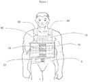
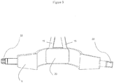
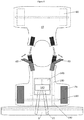
- a belt 5 for a weighted vest 10 is shown in Figure 1 and Figure 2 .
- the belt 5 comprises two belt-connectors 15, extending from the belt 5 in a direction generally upwards and in line with the back of a wearer.
- the belt-connectors 15 are received by a weighted vest 10 of the body armour type.
- the belt 5 comprises padded regions 20 and a snap fit retainer 22.
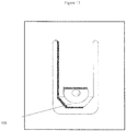
- Figure 4 shows in detail, the retention of the belt-connectors 15 within the belt 5, using in this example, elasticated means 25.
- Figure 5 shows a belt-connector 15 which in this example has two straps 30, 35 extending there from, a first strap 30 of a hook-and-loop construction for fixing within a recess in the belts 5, the second strap 35 which is slightly longer, for receipt in a receiver in the vest 10 as shown in Figure 6 .
- the belt-connectors 15 are secured in position in fabric receiving pockets using buckles 50.
- the belt-connectors 15 of this example are of fibreglass (the material is fibre glass although it could be carbon fibre if lighter and stronger rods are required) construction and are covered in a hardwearing nylon 55. This nylon 55 covering is also applied to the belt 5 itself, including the belt-connectors 15.
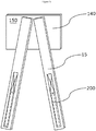
- the two belt connectors 15 may be secured in position using an outer panel 140 and an inner panel 145 of a hook-and-loop fastening (as shown in Figures 7 and 8 ).
- Figure 7a shows belt-connectors 15, which in this example are sewn to a first surface 150 of the outer panel 140, a loop fastening panel.
- the panel 140 comprises an ABS plastic support plate covered on a first surface 150 with a hook-part of a hook-and-loop fastening.
- Inner panel 145 comprises a loop-part of a hook-and-loop fastening.
- FIGs 7a-e the belt-connectors 15 are received in pockets 155 and fixed in position in the pockets 155 using hook and loop fastenings 160, 165.
- an external covering 168 of the belt 5 has been illustrated using dotted lines to show the interior of the belt 5
- Figure 7b provides a schematic representation of the belt 5 as it would be seen.
- this receiving method in the belt 5 may be combined with any of the other features of the belt 5, mounting plate 85 and vest 10.
- Figures 7c , 7d and 7e each show the belt-connectors 15 when secured to outer panel 140.
- Figure 7c shows one half of a hook-and-loop fastening 200 used to fasten the belt-connectors to the belt 5.
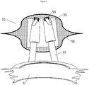
- Figure 7a additionally shows the presence of a rectangular stabilising insert 170, in this example the insert is GRP of size 150mm x 110 mm x 4 mm.
- the insert 170 is held in position relative to the belt connectors 15 and the belt 5 using hook and loop fastening 175.
- the stabilising insert 170 is positioned within the belt 5 such that it is substantially centralised on the spine of the wearer in use.
- Figure 7e further shows the belt 5 in use, although without the vest 10 for clarity. It can clearly be seen that the belt-connectors 15 are substantially aligned on either side of the spine, extending upwards roughly parallel to the back of the wearer.
- Figure 8 shows the belt-connectors 15 and outer panel 140 of Figure 7 when connected to vest 10. Specifically, the belt-connectors 15 are shown as being stitched to a side of outer panel 140 away from the loop half of the hook-and-loop fastening, the loop side of outer panel 140 being fastened to inner panel (the "hook" half of the hook-and-loop fastening) 145.
- Figure 8 also shows weight-bearing elements 180 which interact with pocket in the vest that carry protective inserts (not shown), to ensure that pocket remains closed in use.
- the weight-bearing elements 180 comprise reinforced fabric webbing straps with hook-and-loop fastenings at the lower end 190, to strengthen the closure 195 of pocket.
- FIG 9 shows a vest 10 which may be connected to the belt 5, this vest 10 has four fastenings, 60, 65, 70, 75, one at each shoulder 60, 65 and one at each side of the torso at the waist, 70, 75, each of hook-and-loop construction.
- the fastenings 70, 75 at the waist are enlarged to help increase core stability and the loop portion 80 of the hook-and-loop fastening extends across the entire front of the vest 10, as is also shown in Figure 10 .
- FIG. 11 to 13 shows a mounting plate 85 of the invention, the mounting plate 85 is contoured as a back plate, for carrying respirator apparatus (not shown).
- the mounting plate 85 is of two-piece construction, comprising a 4mm moulded high density polyethylene plastics plate 90, of width 290 mm at the widest point and length 515 mm at the longest point with metal supports 95 bolted to the plate 90.
- the mounting plate 85 has been painted to improve aesthetic appeal and to improve damage resistance.
- the mounting plate 85 comprises a handle 100, which is at the top of the mounting plate 85 in use, six barbed retaining clips 105 are arranged in pairs on opposite sides of the plate 85 down the vertical axis of the plate 85.
- Each pair of retaining clips 105 are of differing length so that these engage with the engagement bands 135 at different points during the mounting process.
- the longest pair of retaining clips 105 is the pair, which, when mounted, appear at the base of the plate 90 with the retaining clips 105 of interim length in the middle position in use and the shortest retaining clips 105 at the upper position in use.
- Clip 105 lengths will typically be in the range 35-60 mm. In this specific example the longest clips are around 55 mm, the mid-length clips 45 mm and the short clips 35 mm.
- a central portion 115 of the mounting plate 85, and a base portion 120 are contoured to receive a respirator tank (not shown), and include slots 125 to allow the tank to be fixed to the mounting plate 85.
- a detachable two-pronged support 130 is provided.
- Figure 14 shows the mounting plate 85 when mounted on a weighted vest 10.
- the barbed retaining clips 105 are engaged with engagement bands 135 in the vest 10, which includes an array of engagement bands 135 formed from strips of resilient non-deforming material stitched at specifically measured intervals to the weighted vest 10.
- the stabilisers 110 are also positioned in engagement bands 135, to stabilise the mounting plate 85 in position relative to the vest 10.
- vests and uses of the invention are capable of being incorporated in the form of a variety of embodiments, only a few of which have been illustrated and described above.
Landscapes
- Health & Medical Sciences (AREA)
- General Health & Medical Sciences (AREA)
- Engineering & Computer Science (AREA)
- Physical Education & Sports Medicine (AREA)
- Textile Engineering (AREA)
- Pulmonology (AREA)
- Orthopedic Medicine & Surgery (AREA)
- Biophysics (AREA)
- Life Sciences & Earth Sciences (AREA)
- Business, Economics & Management (AREA)
- Emergency Management (AREA)
- General Engineering & Computer Science (AREA)
- Professional, Industrial, Or Sporting Protective Garments (AREA)
- Outer Garments And Coats (AREA)
Claims (17)
- Gilet alourdi (10) comportant une ceinture (5) recevant une charge ;
la ceinture comportant un connecteur de ceinture (15), allongé pour recevoir une charge du gilet alourdi, un insert stabilisant (170) au dos de la ceinture et un organe de retenue (22),
le gilet alourdi comportant un récepteur (40) du connecteur de ceinture, gilet caractérisé en ce que
le connecteur de ceinture s'étend dans une direction généralement montante, alignée sur le dos de l'utilisateur, le connecteur de ceinture comportant une tige essentiellement rigide, et
le connecteur de ceinture étant réglable de façon variable, constante et à réglage automatique pour le mouvement latéral de façon à soutenir et à étaler les effets du poids porté. - Gilet selon la revendication 1,
dans lequel
le récepteur comporte un système de fixation à boucle et crochet (160, 165). - Gilet selon la revendication 1,
comportant une partie avant et une partie arrière et une fixation. - Gilet selon la revendication 3,
dans lequel la partie avant et la partie arrière sont reliées de manière détachable. - Gilet selon l'une quelconque des revendications précédentes,
dans lequel la ceinture comporte deux connecteurs de ceinture, les connecteurs de ceinture formant un châssis A, un châssis X ou étant parallèles. - Gilet selon l'une quelconque des revendications précédentes,
dans lequel le connecteur de ceinture est détachable de la ceinture. - Gilet selon l'une quelconque des revendications précédentes,
dans lequel l'organe de retenue est choisi parmi : une fixation à boucle et crochet, des broches à pression, des boutons, des tirettes, des griffes, une fermeture à boucle et des combinaisons de tels moyens. - Gilet selon l'une quelconque des revendications précédentes,
dans lequel le gilet comporte en outre un rembourrage et/ou la ceinture comporte en outre des poches d'air. - Gilet selon l'une quelconque des revendications précédentes,
comportant en outre une plaque de montage pour un paquet comportant au moins une ou plusieurs boucles de retenue pour s'engager avec le gilet alourdi. - Gilet selon la revendication 9,
dans lequel les boucles de retenue font corps avec la plaque. - Gilet selon la revendication 9 ou 10,
dans lequel il y a un nombre pair de boucles de retenue. - Gilet selon l'une des revendications 9 à 11,
dans lequel les boucles de retenue sont réparties le long d'un axe vertical de la plaque. - Gilet selon l'une des revendications 9 à 12,
dans lequel la plaque de montage comporte en outre au moins un stabilisateur (14). - Gilet selon l'une des revendications 9 à 13,
dans lequel la plaque de montage a une surface pour porter un appareil. - Gilet selon la revendication 14,
dans lequel la plaque de montage est en polyéthylène haute densité, en aluminium, en polystyrène, en polypropylène ou des combinaisons de ceux-ci. - Gilet selon l'une des revendications 9 à 15,
dans lequel le gilet comporte des organes de retenue pour la plaque de montage, sur une surface externe du gilet. - Gilet selon la revendication 16,
dans lequel le gilet est choisi parmi : gilet d'exercice alourdi, pièce armée, panneau sandwich, ruban et harnais de poitrine.
Applications Claiming Priority (3)
| Application Number | Priority Date | Filing Date | Title |
|---|---|---|---|
| GB201222709A GB201222709D0 (en) | 2012-12-17 | 2012-12-17 | Load-bearing belt |
| GB201302516A GB201302516D0 (en) | 2013-02-13 | 2013-02-13 | Mounting plate |
| PCT/GB2013/053314 WO2014096797A1 (fr) | 2012-12-17 | 2013-12-17 | Gilet |
Publications (2)
| Publication Number | Publication Date |
|---|---|
| EP2931079A1 EP2931079A1 (fr) | 2015-10-21 |
| EP2931079B1 true EP2931079B1 (fr) | 2020-09-09 |
Family
ID=49780090
Family Applications (1)
| Application Number | Title | Priority Date | Filing Date |
|---|---|---|---|
| EP13808197.1A Active EP2931079B1 (fr) | 2012-12-17 | 2013-12-17 | Gilet |
Country Status (4)
| Country | Link |
|---|---|
| US (1) | US20150342329A1 (fr) |
| EP (1) | EP2931079B1 (fr) |
| GB (1) | GB2524205B (fr) |
| WO (1) | WO2014096797A1 (fr) |
Cited By (1)
| Publication number | Priority date | Publication date | Assignee | Title |
|---|---|---|---|---|
| US11690438B2 (en) * | 2020-07-07 | 2023-07-04 | Bushido Tactical, Llc | Breacher's modular tool carrying system |
Families Citing this family (20)
| Publication number | Priority date | Publication date | Assignee | Title |
|---|---|---|---|---|
| US9604080B2 (en) | 2013-09-27 | 2017-03-28 | Scott Health & Safety Ltd. | Carrying plate for breathing apparatus |
| GB201317249D0 (en) * | 2013-09-27 | 2013-11-13 | Scott Health & Safety Ltd | Carrying plate for breathing apparatus |
| US9700122B2 (en) * | 2013-10-22 | 2017-07-11 | Dept. Of The Navy, A U.S. Government Agency, By The U.S. Marine Corps | Central osteoarticular relief and performance structured load distribution system device and modular scalable vest system |
| US9808666B1 (en) * | 2014-04-21 | 2017-11-07 | Colin M. BURKINSHAW | Full body exercise apparatus |
| CN105192969B (zh) * | 2015-10-23 | 2016-08-17 | 南京际华三五二一特种装备有限公司 | 一种作战背心上的插袢式连接装置 |
| US10786382B2 (en) * | 2016-10-25 | 2020-09-29 | Jargalsaikhan Shagdar | Multifunctional vest for posture correcting, pain relieving and workout boosting |
| DE102017105574A1 (de) * | 2017-03-15 | 2018-09-20 | Nuno Miguel Da Silva Santos | Tragesystem zur Aufnahme von Gewichten |
| TWM557098U (zh) * | 2017-12-14 | 2018-03-21 | Lin K Y Guo Yuan | 可裝配外筋骨保護組件的上衣 |
| US20190200572A1 (en) * | 2017-12-29 | 2019-07-04 | Central Lake Armor Express, Inc. | Canine ballistic carrier vest |
| CN108126303A (zh) * | 2018-02-01 | 2018-06-08 | 重庆宝立通科技有限公司 | 一种可拆卸式健身绑腿负重袋 |
| KR101892018B1 (ko) * | 2018-04-13 | 2018-09-28 | 주식회사 산청 | 방탄조끼 |
| US11278759B2 (en) * | 2019-03-13 | 2022-03-22 | Ken Fewell | Enhanced exercise vest |
| US11079203B2 (en) * | 2019-03-22 | 2021-08-03 | Aardvark | Three-piece tactical cummerbund |
| USD940798S1 (en) * | 2020-04-08 | 2022-01-11 | Coulter Ventures, Llc. | Weight carrier vest |
| AU2021260168A1 (en) * | 2020-04-20 | 2022-11-24 | Naipaul Bassoo | Training vest apparatuses of multi-resistance for sports performance, military training, flotation device and for leisure activities |
| US11564459B2 (en) | 2021-03-30 | 2023-01-31 | Central Lake Armor Express, Inc. | Buckle assembly |
| USD979849S1 (en) * | 2021-03-30 | 2023-02-28 | Central Lake Armor Express, Inc. | Ballistic carrier garment |
| USD979848S1 (en) * | 2021-03-30 | 2023-02-28 | Central Lake Armor Express, Inc. | Ballistic carrier garment |
| US20220390210A1 (en) * | 2021-06-03 | 2022-12-08 | Fechheimer Brothers Company | Cover for ballistic carrier |
| KR20230000364A (ko) * | 2021-06-24 | 2023-01-02 | (주)나라물산 | 사용의 확장성을 갖는 조끼. |
Citations (1)
| Publication number | Priority date | Publication date | Assignee | Title |
|---|---|---|---|---|
| US20100294820A1 (en) * | 2009-05-22 | 2010-11-25 | Neibarger John E | Carrier system |
Family Cites Families (14)
| Publication number | Priority date | Publication date | Assignee | Title |
|---|---|---|---|---|
| US5341974A (en) * | 1992-06-19 | 1994-08-30 | Mont-Bell Co., Ltd. | Back bag |
| FR2733129B1 (fr) * | 1995-04-20 | 1997-05-30 | Decathlon Sa | Dispositif de reglage et de blocage des bretelles de portage d'un sac a dos |
| US5789327A (en) * | 1995-08-28 | 1998-08-04 | Rousseau; Wm. Richard | Armor panel |
| US5954253A (en) * | 1996-06-26 | 1999-09-21 | Johnson Worldwide Associates, Inc. | Flexible frame load carrying system |
| US6607108B2 (en) * | 2001-02-13 | 2003-08-19 | Recreational Equipment, Inc. | Load transfer and stabilization system for backpacks |
| SE0401899L (sv) * | 2004-07-20 | 2005-07-05 | Hagloefs Scandinavia Ab | Höftbälte för ryggsäck |
| US7774864B2 (en) * | 2004-11-05 | 2010-08-17 | Safari Land Ltd., Inc. | Vest and pocket fastening system |
| NO322177B1 (no) * | 2005-01-13 | 2006-08-21 | Bergans Fritid As | Opplagring av et hoftebelte til en ryggsekk |
| US9113697B2 (en) * | 2007-03-20 | 2015-08-25 | Nemo Equipment, Inc. | Ergonomic segmented pack |
| US9185964B2 (en) * | 2009-06-30 | 2015-11-17 | LineWeight, LLC | Personal load distribution device |
| IL202148A0 (en) * | 2009-11-16 | 2010-11-30 | Plasan Sasa Ltd | Load carrying system |
| WO2011109453A1 (fr) * | 2010-03-01 | 2011-09-09 | Kdh Defense Systems, Inc. | Répartition de poids, dispositif de support et système pour gilet pare-balles |
| DE102010029035B4 (de) * | 2010-05-17 | 2019-10-31 | Hexonia Gmbh | Trägersystem mit einem Front- und Rückenteil und Mitteln zur Befestigung an einem menschlichen Oberkörper |
| DE102011075683A1 (de) * | 2011-05-11 | 2012-11-15 | Hexonia Gmbh | Modulares Tragsystem |
-
2013
- 2013-12-17 US US14/653,046 patent/US20150342329A1/en not_active Abandoned
- 2013-12-17 WO PCT/GB2013/053314 patent/WO2014096797A1/fr active Application Filing
- 2013-12-17 GB GB1512393.8A patent/GB2524205B/en active Active
- 2013-12-17 EP EP13808197.1A patent/EP2931079B1/fr active Active
Patent Citations (1)
| Publication number | Priority date | Publication date | Assignee | Title |
|---|---|---|---|---|
| US20100294820A1 (en) * | 2009-05-22 | 2010-11-25 | Neibarger John E | Carrier system |
Cited By (1)
| Publication number | Priority date | Publication date | Assignee | Title |
|---|---|---|---|---|
| US11690438B2 (en) * | 2020-07-07 | 2023-07-04 | Bushido Tactical, Llc | Breacher's modular tool carrying system |
Also Published As
| Publication number | Publication date |
|---|---|
| GB201512393D0 (en) | 2015-08-19 |
| GB2524205A (en) | 2015-09-16 |
| WO2014096797A1 (fr) | 2014-06-26 |
| EP2931079A1 (fr) | 2015-10-21 |
| US20150342329A1 (en) | 2015-12-03 |
| GB2524205B (en) | 2016-06-15 |
Similar Documents
| Publication | Publication Date | Title |
|---|---|---|
| EP2931079B1 (fr) | Gilet | |
| EP2750541B1 (fr) | Harnais de support de vêtement blindé | |
| US20210339069A1 (en) | Weight Plate Carrier Vest | |
| US11041696B2 (en) | Load bearing harness | |
| US8990971B2 (en) | Load bearing tactical vest frame | |
| US20090282595A1 (en) | Antiballistic Garment | |
| US20120132066A1 (en) | Body armor ballistic plate carrier | |
| US20120132065A1 (en) | Body armor ballistic plate carrier | |
| US20180292177A1 (en) | Molle-compatible apparatus | |
| US20130312150A1 (en) | Personal load-carrying system | |
| WO2016015104A1 (fr) | Dispositif de support | |
| US20110231976A1 (en) | Weight Distribution and Support Device and System for an Armor Vest | |
| EP2324731A2 (fr) | Système de support de charge | |
| US20140263519A1 (en) | Backpack frame system with slotted frame | |
| US8992452B2 (en) | Load carrier frame and system | |
| US9766044B2 (en) | Protective system for carrying equipment | |
| WO2009151643A2 (fr) | Système de support de gilet pare-balles | |
| US20160022017A1 (en) | Improved personal carrier | |
| WO2006039846A1 (fr) | Harnais multifonction | |
| KR102530468B1 (ko) | 방탄복 | |
| US20240011744A1 (en) | Ballistic-Resistant Garment | |
| AU2021307413A1 (en) | Weight plate carrier vest | |
| AU2014208260B1 (en) | A Support Device |
Legal Events
| Date | Code | Title | Description |
|---|---|---|---|
| PUAI | Public reference made under article 153(3) epc to a published international application that has entered the european phase |
Free format text: ORIGINAL CODE: 0009012 |
|
| 17P | Request for examination filed |
Effective date: 20150710 |
|
| AK | Designated contracting states |
Kind code of ref document: A1 Designated state(s): AL AT BE BG CH CY CZ DE DK EE ES FI FR GB GR HR HU IE IS IT LI LT LU LV MC MK MT NL NO PL PT RO RS SE SI SK SM TR |
|
| AX | Request for extension of the european patent |
Extension state: BA ME |
|
| DAX | Request for extension of the european patent (deleted) | ||
| STAA | Information on the status of an ep patent application or granted ep patent |
Free format text: STATUS: EXAMINATION IS IN PROGRESS |
|
| 17Q | First examination report despatched |
Effective date: 20180620 |
|
| GRAP | Despatch of communication of intention to grant a patent |
Free format text: ORIGINAL CODE: EPIDOSNIGR1 |
|
| STAA | Information on the status of an ep patent application or granted ep patent |
Free format text: STATUS: GRANT OF PATENT IS INTENDED |
|
| INTG | Intention to grant announced |
Effective date: 20200319 |
|
| GRAS | Grant fee paid |
Free format text: ORIGINAL CODE: EPIDOSNIGR3 |
|
| GRAA | (expected) grant |
Free format text: ORIGINAL CODE: 0009210 |
|
| STAA | Information on the status of an ep patent application or granted ep patent |
Free format text: STATUS: THE PATENT HAS BEEN GRANTED |
|
| AK | Designated contracting states |
Kind code of ref document: B1 Designated state(s): AL AT BE BG CH CY CZ DE DK EE ES FI FR GB GR HR HU IE IS IT LI LT LU LV MC MK MT NL NO PL PT RO RS SE SI SK SM TR |
|
| REG | Reference to a national code |
Ref country code: GB Ref legal event code: FG4D |
|
| RIN1 | Information on inventor provided before grant (corrected) |
Inventor name: FORMOSA, RAY |
|
| REG | Reference to a national code |
Ref country code: AT Ref legal event code: REF Ref document number: 1310475 Country of ref document: AT Kind code of ref document: T Effective date: 20200915 Ref country code: CH Ref legal event code: EP |
|
| REG | Reference to a national code |
Ref country code: IE Ref legal event code: FG4D |
|
| REG | Reference to a national code |
Ref country code: DE Ref legal event code: R096 Ref document number: 602013072420 Country of ref document: DE |
|
| REG | Reference to a national code |
Ref country code: LT Ref legal event code: MG4D |
|
| PG25 | Lapsed in a contracting state [announced via postgrant information from national office to epo] |
Ref country code: GR Free format text: LAPSE BECAUSE OF FAILURE TO SUBMIT A TRANSLATION OF THE DESCRIPTION OR TO PAY THE FEE WITHIN THE PRESCRIBED TIME-LIMIT Effective date: 20201210 Ref country code: HR Free format text: LAPSE BECAUSE OF FAILURE TO SUBMIT A TRANSLATION OF THE DESCRIPTION OR TO PAY THE FEE WITHIN THE PRESCRIBED TIME-LIMIT Effective date: 20200909 Ref country code: LT Free format text: LAPSE BECAUSE OF FAILURE TO SUBMIT A TRANSLATION OF THE DESCRIPTION OR TO PAY THE FEE WITHIN THE PRESCRIBED TIME-LIMIT Effective date: 20200909 Ref country code: FI Free format text: LAPSE BECAUSE OF FAILURE TO SUBMIT A TRANSLATION OF THE DESCRIPTION OR TO PAY THE FEE WITHIN THE PRESCRIBED TIME-LIMIT Effective date: 20200909 Ref country code: SE Free format text: LAPSE BECAUSE OF FAILURE TO SUBMIT A TRANSLATION OF THE DESCRIPTION OR TO PAY THE FEE WITHIN THE PRESCRIBED TIME-LIMIT Effective date: 20200909 Ref country code: BG Free format text: LAPSE BECAUSE OF FAILURE TO SUBMIT A TRANSLATION OF THE DESCRIPTION OR TO PAY THE FEE WITHIN THE PRESCRIBED TIME-LIMIT Effective date: 20201209 Ref country code: NO Free format text: LAPSE BECAUSE OF FAILURE TO SUBMIT A TRANSLATION OF THE DESCRIPTION OR TO PAY THE FEE WITHIN THE PRESCRIBED TIME-LIMIT Effective date: 20201209 |
|
| REG | Reference to a national code |
Ref country code: AT Ref legal event code: MK05 Ref document number: 1310475 Country of ref document: AT Kind code of ref document: T Effective date: 20200909 |
|
| REG | Reference to a national code |
Ref country code: NL Ref legal event code: MP Effective date: 20200909 |
|
| PG25 | Lapsed in a contracting state [announced via postgrant information from national office to epo] |
Ref country code: RS Free format text: LAPSE BECAUSE OF FAILURE TO SUBMIT A TRANSLATION OF THE DESCRIPTION OR TO PAY THE FEE WITHIN THE PRESCRIBED TIME-LIMIT Effective date: 20200909 Ref country code: PL Free format text: LAPSE BECAUSE OF FAILURE TO SUBMIT A TRANSLATION OF THE DESCRIPTION OR TO PAY THE FEE WITHIN THE PRESCRIBED TIME-LIMIT Effective date: 20200909 Ref country code: LV Free format text: LAPSE BECAUSE OF FAILURE TO SUBMIT A TRANSLATION OF THE DESCRIPTION OR TO PAY THE FEE WITHIN THE PRESCRIBED TIME-LIMIT Effective date: 20200909 |
|
| PG25 | Lapsed in a contracting state [announced via postgrant information from national office to epo] |
Ref country code: SM Free format text: LAPSE BECAUSE OF FAILURE TO SUBMIT A TRANSLATION OF THE DESCRIPTION OR TO PAY THE FEE WITHIN THE PRESCRIBED TIME-LIMIT Effective date: 20200909 Ref country code: RO Free format text: LAPSE BECAUSE OF FAILURE TO SUBMIT A TRANSLATION OF THE DESCRIPTION OR TO PAY THE FEE WITHIN THE PRESCRIBED TIME-LIMIT Effective date: 20200909 Ref country code: PT Free format text: LAPSE BECAUSE OF FAILURE TO SUBMIT A TRANSLATION OF THE DESCRIPTION OR TO PAY THE FEE WITHIN THE PRESCRIBED TIME-LIMIT Effective date: 20210111 Ref country code: NL Free format text: LAPSE BECAUSE OF FAILURE TO SUBMIT A TRANSLATION OF THE DESCRIPTION OR TO PAY THE FEE WITHIN THE PRESCRIBED TIME-LIMIT Effective date: 20200909 Ref country code: EE Free format text: LAPSE BECAUSE OF FAILURE TO SUBMIT A TRANSLATION OF THE DESCRIPTION OR TO PAY THE FEE WITHIN THE PRESCRIBED TIME-LIMIT Effective date: 20200909 Ref country code: CZ Free format text: LAPSE BECAUSE OF FAILURE TO SUBMIT A TRANSLATION OF THE DESCRIPTION OR TO PAY THE FEE WITHIN THE PRESCRIBED TIME-LIMIT Effective date: 20200909 |
|
| PGFP | Annual fee paid to national office [announced via postgrant information from national office to epo] |
Ref country code: IE Payment date: 20210223 Year of fee payment: 8 |
|
| PG25 | Lapsed in a contracting state [announced via postgrant information from national office to epo] |
Ref country code: AT Free format text: LAPSE BECAUSE OF FAILURE TO SUBMIT A TRANSLATION OF THE DESCRIPTION OR TO PAY THE FEE WITHIN THE PRESCRIBED TIME-LIMIT Effective date: 20200909 Ref country code: AL Free format text: LAPSE BECAUSE OF FAILURE TO SUBMIT A TRANSLATION OF THE DESCRIPTION OR TO PAY THE FEE WITHIN THE PRESCRIBED TIME-LIMIT Effective date: 20200909 Ref country code: ES Free format text: LAPSE BECAUSE OF FAILURE TO SUBMIT A TRANSLATION OF THE DESCRIPTION OR TO PAY THE FEE WITHIN THE PRESCRIBED TIME-LIMIT Effective date: 20200909 Ref country code: IS Free format text: LAPSE BECAUSE OF FAILURE TO SUBMIT A TRANSLATION OF THE DESCRIPTION OR TO PAY THE FEE WITHIN THE PRESCRIBED TIME-LIMIT Effective date: 20210109 |
|
| REG | Reference to a national code |
Ref country code: DE Ref legal event code: R097 Ref document number: 602013072420 Country of ref document: DE |
|
| PG25 | Lapsed in a contracting state [announced via postgrant information from national office to epo] |
Ref country code: SK Free format text: LAPSE BECAUSE OF FAILURE TO SUBMIT A TRANSLATION OF THE DESCRIPTION OR TO PAY THE FEE WITHIN THE PRESCRIBED TIME-LIMIT Effective date: 20200909 |
|
| PLBE | No opposition filed within time limit |
Free format text: ORIGINAL CODE: 0009261 |
|
| STAA | Information on the status of an ep patent application or granted ep patent |
Free format text: STATUS: NO OPPOSITION FILED WITHIN TIME LIMIT |
|
| REG | Reference to a national code |
Ref country code: CH Ref legal event code: PL |
|
| 26N | No opposition filed |
Effective date: 20210610 |
|
| PG25 | Lapsed in a contracting state [announced via postgrant information from national office to epo] |
Ref country code: SI Free format text: LAPSE BECAUSE OF FAILURE TO SUBMIT A TRANSLATION OF THE DESCRIPTION OR TO PAY THE FEE WITHIN THE PRESCRIBED TIME-LIMIT Effective date: 20200909 Ref country code: DK Free format text: LAPSE BECAUSE OF FAILURE TO SUBMIT A TRANSLATION OF THE DESCRIPTION OR TO PAY THE FEE WITHIN THE PRESCRIBED TIME-LIMIT Effective date: 20200909 Ref country code: MC Free format text: LAPSE BECAUSE OF FAILURE TO SUBMIT A TRANSLATION OF THE DESCRIPTION OR TO PAY THE FEE WITHIN THE PRESCRIBED TIME-LIMIT Effective date: 20200909 |
|
| REG | Reference to a national code |
Ref country code: BE Ref legal event code: MM Effective date: 20201231 |
|
| PG25 | Lapsed in a contracting state [announced via postgrant information from national office to epo] |
Ref country code: IT Free format text: LAPSE BECAUSE OF FAILURE TO SUBMIT A TRANSLATION OF THE DESCRIPTION OR TO PAY THE FEE WITHIN THE PRESCRIBED TIME-LIMIT Effective date: 20200909 Ref country code: LU Free format text: LAPSE BECAUSE OF NON-PAYMENT OF DUE FEES Effective date: 20201217 |
|
| PG25 | Lapsed in a contracting state [announced via postgrant information from national office to epo] |
Ref country code: LI Free format text: LAPSE BECAUSE OF NON-PAYMENT OF DUE FEES Effective date: 20201231 Ref country code: CH Free format text: LAPSE BECAUSE OF NON-PAYMENT OF DUE FEES Effective date: 20201231 |
|
| PG25 | Lapsed in a contracting state [announced via postgrant information from national office to epo] |
Ref country code: TR Free format text: LAPSE BECAUSE OF FAILURE TO SUBMIT A TRANSLATION OF THE DESCRIPTION OR TO PAY THE FEE WITHIN THE PRESCRIBED TIME-LIMIT Effective date: 20200909 Ref country code: MT Free format text: LAPSE BECAUSE OF FAILURE TO SUBMIT A TRANSLATION OF THE DESCRIPTION OR TO PAY THE FEE WITHIN THE PRESCRIBED TIME-LIMIT Effective date: 20200909 Ref country code: CY Free format text: LAPSE BECAUSE OF FAILURE TO SUBMIT A TRANSLATION OF THE DESCRIPTION OR TO PAY THE FEE WITHIN THE PRESCRIBED TIME-LIMIT Effective date: 20200909 |
|
| PG25 | Lapsed in a contracting state [announced via postgrant information from national office to epo] |
Ref country code: MK Free format text: LAPSE BECAUSE OF FAILURE TO SUBMIT A TRANSLATION OF THE DESCRIPTION OR TO PAY THE FEE WITHIN THE PRESCRIBED TIME-LIMIT Effective date: 20200909 |
|
| PG25 | Lapsed in a contracting state [announced via postgrant information from national office to epo] |
Ref country code: BE Free format text: LAPSE BECAUSE OF NON-PAYMENT OF DUE FEES Effective date: 20201231 |
|
| PG25 | Lapsed in a contracting state [announced via postgrant information from national office to epo] |
Ref country code: IE Free format text: LAPSE BECAUSE OF NON-PAYMENT OF DUE FEES Effective date: 20211217 |
|
| PGFP | Annual fee paid to national office [announced via postgrant information from national office to epo] |
Ref country code: GB Payment date: 20231214 Year of fee payment: 11 |
|
| PGFP | Annual fee paid to national office [announced via postgrant information from national office to epo] |
Ref country code: FR Payment date: 20231221 Year of fee payment: 11 Ref country code: DE Payment date: 20231220 Year of fee payment: 11 |