EP2931006A1 - Hotplate - Google Patents
Hotplate Download PDFInfo
- Publication number
- EP2931006A1 EP2931006A1 EP14164057.3A EP14164057A EP2931006A1 EP 2931006 A1 EP2931006 A1 EP 2931006A1 EP 14164057 A EP14164057 A EP 14164057A EP 2931006 A1 EP2931006 A1 EP 2931006A1
- Authority
- EP
- European Patent Office
- Prior art keywords
- rails
- transverse
- assemblies
- longitudinal
- rail
- Prior art date
- Legal status (The legal status is an assumption and is not a legal conclusion. Google has not performed a legal analysis and makes no representation as to the accuracy of the status listed.)
- Granted
Links
- 230000000712 assembly Effects 0.000 claims abstract description 30
- 238000000429 assembly Methods 0.000 claims abstract description 30
- 125000006850 spacer group Chemical group 0.000 claims description 3
- 238000010411 cooking Methods 0.000 claims 1
- 230000006698 induction Effects 0.000 description 2
- 230000015572 biosynthetic process Effects 0.000 description 1
- 150000001875 compounds Chemical class 0.000 description 1
- 238000006073 displacement reaction Methods 0.000 description 1
- 230000005672 electromagnetic field Effects 0.000 description 1
- 238000012423 maintenance Methods 0.000 description 1
- 239000002184 metal Substances 0.000 description 1
- 230000000284 resting effect Effects 0.000 description 1
- 238000010079 rubber tapping Methods 0.000 description 1
- 238000004904 shortening Methods 0.000 description 1
Images


Classifications
-
- H—ELECTRICITY
- H05—ELECTRIC TECHNIQUES NOT OTHERWISE PROVIDED FOR
- H05B—ELECTRIC HEATING; ELECTRIC LIGHT SOURCES NOT OTHERWISE PROVIDED FOR; CIRCUIT ARRANGEMENTS FOR ELECTRIC LIGHT SOURCES, IN GENERAL
- H05B6/00—Heating by electric, magnetic or electromagnetic fields
- H05B6/02—Induction heating
- H05B6/10—Induction heating apparatus, other than furnaces, for specific applications
- H05B6/12—Cooking devices
- H05B6/1209—Cooking devices induction cooking plates or the like and devices to be used in combination with them
- H05B6/1245—Cooking devices induction cooking plates or the like and devices to be used in combination with them with special coil arrangements
-
- F—MECHANICAL ENGINEERING; LIGHTING; HEATING; WEAPONS; BLASTING
- F24—HEATING; RANGES; VENTILATING
- F24C—DOMESTIC STOVES OR RANGES ; DETAILS OF DOMESTIC STOVES OR RANGES, OF GENERAL APPLICATION
- F24C15/00—Details
- F24C15/10—Tops, e.g. hot plates; Rings
- F24C15/102—Tops, e.g. hot plates; Rings electrically heated
-
- F—MECHANICAL ENGINEERING; LIGHTING; HEATING; WEAPONS; BLASTING
- F24—HEATING; RANGES; VENTILATING
- F24C—DOMESTIC STOVES OR RANGES ; DETAILS OF DOMESTIC STOVES OR RANGES, OF GENERAL APPLICATION
- F24C7/00—Stoves or ranges heated by electric energy
- F24C7/06—Arrangement or mounting of electric heating elements
- F24C7/067—Arrangement or mounting of electric heating elements on ranges
-
- H—ELECTRICITY
- H05—ELECTRIC TECHNIQUES NOT OTHERWISE PROVIDED FOR
- H05B—ELECTRIC HEATING; ELECTRIC LIGHT SOURCES NOT OTHERWISE PROVIDED FOR; CIRCUIT ARRANGEMENTS FOR ELECTRIC LIGHT SOURCES, IN GENERAL
- H05B2206/00—Aspects relating to heating by electric, magnetic, or electromagnetic fields covered by group H05B6/00
- H05B2206/02—Induction heating
- H05B2206/022—Special supports for the induction coils
-
- Y—GENERAL TAGGING OF NEW TECHNOLOGICAL DEVELOPMENTS; GENERAL TAGGING OF CROSS-SECTIONAL TECHNOLOGIES SPANNING OVER SEVERAL SECTIONS OF THE IPC; TECHNICAL SUBJECTS COVERED BY FORMER USPC CROSS-REFERENCE ART COLLECTIONS [XRACs] AND DIGESTS
- Y02—TECHNOLOGIES OR APPLICATIONS FOR MITIGATION OR ADAPTATION AGAINST CLIMATE CHANGE
- Y02B—CLIMATE CHANGE MITIGATION TECHNOLOGIES RELATED TO BUILDINGS, e.g. HOUSING, HOUSE APPLIANCES OR RELATED END-USER APPLICATIONS
- Y02B40/00—Technologies aiming at improving the efficiency of home appliances, e.g. induction cooking or efficient technologies for refrigerators, freezers or dish washers
Definitions
- the invention relates to a hob with a number of inductors, a number of electrical components, each inductor is associated with an electrical assembly, and with a support system for holding the modules.
- a generic hob is, for example, in the DE 202009000991 U1 shown.
- a carrier system used there has transverse and longitudinal members, wherein the cross members can be attached to defined, ie discrete locations of respective side members. Assemblies can also be attached to the cross members at defined locations.
- the invention has for its object to allow for a cooktop a more accurate positioning of assemblies under the respective inductor with little effort.
- the hob has a number of inductors, a number of electrical assemblies, each associated with each inductor having an electrical assembly, and a support system for holding the assemblies.
- the carrier system has at least one first longitudinal rail and one second longitudinal rail, which are arranged parallel to one another and along which at least one assembly is infinitely displaceable. This allows a more accurate Positioning of the assembly below the respective inductor, since the assembly can no longer be fixed only in discrete positions, but can be continuously adapted to the position of the inductor. This allows a particularly good shortening of electrical connections between the inductor and the assembly, which minimizes line losses largely.
- the inductors or induction coils are known to heat a standing on the hob cookware. For this purpose, they are typically excited by means of an alternating electric current and then emit an electromagnetic field. For the application of such an alternating current typically serves the respectively associated assembly, which contains suitable components for this, in particular power electronics.
- the carrier system serves to hold the modules in a certain position in the hob.
- the hob has a number of further longitudinal rails, which are arranged parallel to the first longitudinal rail, and along which a number of modules are continuously displaceable. This makes it possible to extend the support system for several adjacent modules also transversely to the longitudinal rails.
- the carrier system has at least one first transverse rail and one second transverse rail, which are arranged parallel to one another and along which at least one assembly is infinitely displaceable or placeable, in order then to be fastened.
- This makes it possible to attach the assemblies at least partially to the cross rails, and thus to obtain additional flexibility in their positioning in a direction transverse to the longitudinal rails.
- the hob has a number of other cross rails, which are arranged parallel to the first cross rail and along which a number of modules is continuously displaceable.
- the just mentioned concept of the transverse rails can be extended in the direction of the longitudinal extent of the longitudinal rails.
- the cross rails are arranged transversely to the longitudinal rails. This may mean, for example, that they are at an angle of 90 ° to each other. However, other angles can also be used, for example, those of approximately 90 °, or even only between 45 ° and almost 90 °.
- a number of modules is attached directly to each two cross rails continuously, further wherein the respective cross rails are attached to two longitudinal rails continuously displaceable.
- the respective modules along the cross rails and along the longitudinal rails can each be continuously adjusted, which allows a particularly free and advantageous positioning. This may apply to an assembly, some assemblies or all assemblies.
- the cross rails are releasably connected by means of a respective screw with the longitudinal rails.
- This may be, for example, a frictional connection, a positive connection or both. This corresponds to a simple design, which is easily solvable for maintenance purposes and also allows an advantageous stepless positioning.
- the number of assemblies with a respective transverse or longitudinal rail by means of a number of screw connections is releasably connected.
- This may also be, for example, a frictional connection, a form fit or both.
- screw connections are preferred because they can be easily attached and detached and allow stepless positioning.
- screws may be provided on each of the top resting rails and sliding nuts or so-called sliding blocks in grooves or slots in the underlying rail.
- a number of assemblies with a respective transverse or longitudinal rail by means of a number of clip connectors, spacers, positioning pins and / or springs are releasably connected. This can be used on other mounting options. This can be particularly advantageous when finished assemblies are used, which are already provided with appropriate fasteners.
- fastening means so screw, clip connectors, spacers, positioning pins and springs can also be combined with each other, for example, some assemblies are connected by a first type of fasteners and other assemblies are connected by other fasteners. Even with an assembly, different fasteners can be used.
- a number of transverse and / or longitudinal rails are each formed as profile rails.
- Such a profile rail may advantageously have a respective groove.
- a simple attitude of the respective assembly and also a simple attachment for example by means of an inserted into the groove screw such as a self-tapping sheet metal screw, achieved.
- the groove can also stabilize an assembly when moving and thus during positioning.
- one or more of the transverse and / or longitudinal rails form a respective wall of a housing of an induction hob, in particular a side wall.
- the hob can be laterally outwardly delimited, the already existing rails already form an outer boundary. Additional components can thus be dispensed with.
- the bottom of the hob can be advantageously closed with a plate.
- the hob can be inserted into a housing pan and / or fixed therein. This is particularly advantageous if the hob is to be used in an already otherwise defined space, such as a stove.
- a number of controls and / or displays are attached to the carrier system. These may be, for example, displays, switches, controls or touch switches. By attaching these elements and / or displays on the carrier system can be dispensed with additional fasteners.
- a respective assembly is located immediately below the inductor to which it is associated. More preferably, a respective inductor is electrically connected by means of a number of coil cables with its associated assembly.
- the length of the coil cable can be kept particularly low in the just described preferred arrangement immediately below the inductor, which minimizes losses in the coil cables. Due to the high transferred power and the long operating time can already be very much Small improvements in the length of the coil cable over the life of a hob calculated to achieve significant savings.
- Fig. 1 shows a cooktop 10 with a carrier system 100.
- the cooktop 10 has a total of three inductors 20 and three electrical assemblies 30, wherein each inductor 20, an assembly 30 is assigned.
- the inductors 20 are thereby electrically connected to the electrical assemblies 30 by means of respective coil cables 35.
- the assemblies 30 are designed to power the inductors 20 and for this purpose also have a suitable, not explicitly shown power electronics.
- controls for the finished hob 10 are provided, which are not shown here.
- the carrier system 100 carries the assemblies 30 and holds them in certain positions.
- the carrier system 100 has a first longitudinal rail 111, a second longitudinal rail 112 parallel thereto, a first transverse rail 121 and a second transverse rail 122 parallel thereto.
- the assemblies 30 are attached directly to the two cross rails 121, 122, whereas the two transverse rails 121, 122 are attached to the two longitudinal rails 111, 112, and also directly.
- the assemblies 30 are along the two transverse rails 121, 122 steplessly or arbitrarily displaced.
- the cross rails 121, 122 along the longitudinal rails 111, 112 are continuously displaceable. How exactly this is done will be discussed below with reference to Fig. 2 described in more detail.
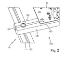
- Fig. 2 shows the attachment of the first cross rail 121 to the first longitudinal rail 111 and the left assembly 30 to the first cross rail 121 in detail.
- the first longitudinal rail 111 has a groove 150, which is open in the illustration upwards.
- the first cross rail 121 has a groove 151, which is also open upwards.
- the respective grooves 150, 151 each extend along the respective longitudinal directions of the rails 111, 121. These can thus also be referred to as profile rails.
- the grooves can be straight in the depth, advantageously they are slightly undercut, particularly advantageous vice versa V-shaped.
- the first transverse rail 121 is fastened to the first longitudinal rail 111 by means of a first screw 152.
- the first screw 152 is first inserted through the groove 151 of the first cross rail 121 and engages in the groove 150 of the first longitudinal rail 111 a.
- the first cross rail 121 has for this purpose a through hole, not shown.
- the cross bar 121 retains its position relative to the first longitudinal rail 111. This corresponds to a simple design of a compound, which is also always solvable by the first screw 152 is unscrewed upwards. It can be used again if necessary in a different position. This allows a stepless or arbitrarily placeable displacement.
- the assembly 30 is attached, inter alia, by means of a second screw 153 to the first cross rail 121.
- the second screw 153 is first pushed through a hole in the assembly 30 and engages further below in the groove 151 of the first cross rail 121 a. This also allows reliable mounting of the assembly 30 without the need for fixed, discrete attachment locations.
- the second screw 153 can be turned upwards. It can then be screwed in another position again to secure the assembly 30 at a different position.
- Fig. 3 shows a two-dimensionally extended embodiment of a hob 10. The individual elements are similar to those already in the Fig. 1 and 2 are shown. However, there are significantly more items available.
- the carrier system 100 of the hob 10 of Fig. 3 has a total of four longitudinal rails 111, 112, 113, 114 and a total of ten cross bars 121, 122, 123, 124, 125, 126, 127, 128, 129, 130 on.
- the cross rails 121 to 130 are in each case attached to two of the longitudinal rails 111, 112, 113, 114. This is done in a similar manner as described above with respect to the Fig. 1 and 2 has been described.
- a respective assembly 30 is attached between each two transverse rails 121 to 130. Again, this is done in a similar way as above with respect to Fig. 1 and 2 described.
- both the assemblies 30 can be displaced along the respective transverse rails 121 to 130, and the transverse rails 121 to 130 can also be displaced at the respective longitudinal rails 111 to 114.
- This allows a particularly free, stepless displaceability of the assemblies 30, whereby they can be ideally arranged under respective inductors.
- Fig. 3 exemplary, possible arrangements of assemblies 30 are shown in which the free positioning has been exploited.
- the respective inductors are in Fig. 3 for the sake of clarity not shown.
- Fig. 4 shows the hob 10 of Fig. 3 , which is inserted in a housing in the form of a tray 200.
- a pan 200 may be arranged, for example, above a baking oven for holding the hob 10.
- the tub 200 may also be formed in a cabinet or substructure upon which the hob 10 is to be disposed for use. With respect to the hob 10 can fully to the description of Fig. 3 to get expelled. A repetition is therefore omitted.
- Fig. 5 shows an alternative embodiment of the hob 200 contained in a pan 10 of Fig. 4 ,
- the respective outer longitudinal rails 111, 114 are formed so that they each form an outer wall of the tub 200.
- the hob 10 is performed with the tub 200 as an integrated module, which can be used for example in suitable substructures or furniture. On the formation of an additional tub can then be dispensed with.
Landscapes
- Engineering & Computer Science (AREA)
- Chemical & Material Sciences (AREA)
- Combustion & Propulsion (AREA)
- Mechanical Engineering (AREA)
- General Engineering & Computer Science (AREA)
- Physics & Mathematics (AREA)
- Electromagnetism (AREA)
- Baking, Grill, Roasting (AREA)
- General Induction Heating (AREA)
Abstract
Ein Kochfeld weist eine Anzahl von Induktoren (20), eine Anzahl von elektrischen Baugruppen (30), wobei jedem Induktor (20) jeweils eine elektrische Baugruppe (30) zugeordnet ist, und ein Trägersystem (100) zum Halten der Baugruppen (30) auf. Das Trägersystem (100) weist zumindest eine erste Längsschiene (111) und eine zweite Längsschiene (112) auf, welche zueinander parallel angeordnet sind und entlang welchen zumindest eine Baugruppe (30) stufenlos verschiebbar ist. So kann ein einfacher und sehr variabler Aufbau erreicht werden.A cooktop has a number of inductors (20), a number of electrical assemblies (30), each inductor (20) each having an electrical assembly (30) associated with it, and a carrier system (100) for holding the assemblies (30) , The carrier system (100) has at least one first longitudinal rail (111) and one second longitudinal rail (112), which are arranged parallel to one another and along which at least one assembly (30) is continuously displaceable. So a simple and very variable structure can be achieved.
Description
Die Erfindung betrifft ein Kochfeld mit einer Anzahl von Induktoren, einer Anzahl von elektrischen Baugruppen, wobei jedem Induktor jeweils eine elektrische Baugruppe zugeordnet ist, und mit einem Trägersystem zum Halten der Baugruppen.The invention relates to a hob with a number of inductors, a number of electrical components, each inductor is associated with an electrical assembly, and with a support system for holding the modules.
Ein gattungsgemäßes Kochfeld ist beispielsweise in der
Um Leitungsverluste möglichst gering zu halten, ist es bei Kochfeldern wünschenswert, jeweilige Baugruppen jeweils unterhalb des Induktors, welchem er zugeordnet ist, anzuordnen. Aufgrund der beim Stand der Technik vorgegebenen diskreten Positionen ist dies bei gattungsgemäßen Kochfeldern nur mit erheblichen Einschränkungen möglich.To keep line losses as low as possible, it is desirable for hobs, each module below the inductor, to which it is assigned to arrange. Due to the discrete positions specified in the prior art, this is only possible with considerable limitations in the case of generic hobs.
Der Erfindung liegt Aufgabe, bei einem Kochfeld eine genauere Positionierung von Baugruppen unter dem jeweiligen Induktor zu ermöglichen bei geringem Aufwand.The invention has for its object to allow for a cooktop a more accurate positioning of assemblies under the respective inductor with little effort.
Diese Aufgabe wird gelöst durch ein Kochfeld mit den Merkmalen des Anspruchs 1. Vorteilhafte sowie bevorzugte Ausgestaltungen der Erfindung sind Gegenstand der weiteren Ansprüche und werden im Folgenden näher erläutert. Der Wortlaut der Ansprüche wird durch ausdrückliche Bezugnahme zum Inhalt der Beschreibung gemacht.This object is achieved by a hob with the features of claim 1. Advantageous and preferred embodiments of the invention are the subject of further claims and are explained in more detail below. The wording of the claims is incorporated herein by express reference.
Das Kochfeld weist eine Anzahl von Induktoren, eine Anzahl von elektrischen Baugruppen, wobei jedem Induktor jeweils eine elektrische Baugruppe zugeordnet ist, und ein Trägersystem zum Halten der Baugruppen auf.The hob has a number of inductors, a number of electrical assemblies, each associated with each inductor having an electrical assembly, and a support system for holding the assemblies.
Erfindungsgemäß ist vorgesehen, dass das Trägersystem zumindest eine erste Längsschiene und eine zweite Längsschiene aufweist, welche zueinander parallel angeordnet sind und entlang welchen zumindest eine Baugruppe stufenlos verschiebbar ist. Dies ermöglicht eine genauere Positionierung der Baugruppe unterhalb des jeweiligen Induktors, da die Baugruppe nicht mehr nur noch in diskreten Positionen befestigt werden kann, sondern vielmehr stufenlos an die Position des Induktors angepasst werden kann. Dies erlaubt eine besonders gute Verkürzung von elektrischen Anschlüssen zwischen dem Induktor und der Baugruppe, was Leitungsverluste weitgehend minimiert.According to the invention, it is provided that the carrier system has at least one first longitudinal rail and one second longitudinal rail, which are arranged parallel to one another and along which at least one assembly is infinitely displaceable. This allows a more accurate Positioning of the assembly below the respective inductor, since the assembly can no longer be fixed only in discrete positions, but can be continuously adapted to the position of the inductor. This allows a particularly good shortening of electrical connections between the inductor and the assembly, which minimizes line losses largely.
Die Induktoren bzw. Induktionsspulen dienen bekanntermaßen dazu, ein auf dem Kochfeld stehendes Kochgeschirr zu beheizen. Hierzu werden sie typischerweise mittels eines elektrischen Wechselstroms angeregt und strahlen dann ein elektromagnetisches Feld ab. Zum Anlegen eines solchen Wechselstroms dient typischerweise die jeweils zugeordnete Baugruppe, welche hierfür geeignete Komponenten enthält, insbesondere Leistungselektronik. Das Trägersystem dient dabei dazu, die Baugruppen in einer bestimmten Position in dem Kochfeld zu halten.The inductors or induction coils are known to heat a standing on the hob cookware. For this purpose, they are typically excited by means of an alternating electric current and then emit an electromagnetic field. For the application of such an alternating current typically serves the respectively associated assembly, which contains suitable components for this, in particular power electronics. The carrier system serves to hold the modules in a certain position in the hob.
Bevorzugt weist das Kochfeld eine Anzahl weiterer Längsschienen auf, welche parallel zu der ersten Längsschiene angeordnet sind, und entlang welchen eine Anzahl der Baugruppen stufenlos verschiebbar sind. Dies ermöglicht es, das Trägersystem für mehrere nebeneinander liegende Baugruppen auch quer zu den Längsschienen zu erweitern.Preferably, the hob has a number of further longitudinal rails, which are arranged parallel to the first longitudinal rail, and along which a number of modules are continuously displaceable. This makes it possible to extend the support system for several adjacent modules also transversely to the longitudinal rails.
Es ist möglich, dass jeweils zwischen zwei parallelen Längsschienen grundsätzlich eine beliebige Anzahl an Baugruppen gehalten werden kann, die nur durch den zur Verfügung stehenden Platz begrenzt wird. Durch die weiteren Längsschienen wird dieses Konzept sozusagen zweidimensional bzw. in einer zweiten Richtung erweitert.It is possible that in each case between two parallel longitudinal rails basically any number of modules can be kept, which is limited only by the available space. The further longitudinal rails extend this concept, so to speak, two-dimensionally or in a second direction.
Bevorzugt weist das Trägersystem zumindest eine erste Querschiene und eine zweite Querschiene auf, welche zueinander parallel angeordnet sind und entlang welchen zumindest eine Baugruppe stufenlos verschiebbar bzw. platzierbar ist, um dann befestigt zu werden. Dies ermöglicht es, die Baugruppen zumindest teilweise an den Querschienen anzubringen, und damit eine zusätzliche Flexibilität in deren Positionierung in einer Richtung quer zu den Längsschienen zu erhalten. Weiter bevorzugt weist das Kochfeld eine Anzahl weiterer Querschienen auf, welche parallel zu der ersten Querschiene angeordnet sind und entlang welchen eine Anzahl der Baugruppen stufenlos verschiebbar ist. Damit kann das eben erwähnte Konzept der Querschienen in der Richtung der Längserstreckung der Längsschienen erweitert werden.Preferably, the carrier system has at least one first transverse rail and one second transverse rail, which are arranged parallel to one another and along which at least one assembly is infinitely displaceable or placeable, in order then to be fastened. This makes it possible to attach the assemblies at least partially to the cross rails, and thus to obtain additional flexibility in their positioning in a direction transverse to the longitudinal rails. More preferably, the hob has a number of other cross rails, which are arranged parallel to the first cross rail and along which a number of modules is continuously displaceable. Thus, the just mentioned concept of the transverse rails can be extended in the direction of the longitudinal extent of the longitudinal rails.
Durch die Kombinationen von weiteren Längsschienen und weiteren Querschienen kann insgesamt eine nahezu beliebige zweidimensionale Skalierung oder Erweiterung des erfindungsgemäßen Konzepts erreicht werden. So können in zwei oder drei Reihen hintereinander mehrere Induktoren samt den zugehörigen Baugruppen nebeneinander platziert werden.Due to the combinations of further longitudinal rails and further cross rails, a total of almost any two-dimensional scaling or expansion of the invention Concept can be achieved. In this way, several inductors and the associated modules can be placed next to each other in two or three rows one behind the other.
Bevorzugt sind die Querschienen quer zu den Längsschienen angeordnet. Dies kann beispielsweise bedeuten, dass sie in einem Winkel von 90° zueinander stehen. Es können jedoch auch andere Winkel verwendet werden, beispielsweise welche von annähernd 90°, oder auch nur zwischen 45° und knapp 90°.Preferably, the cross rails are arranged transversely to the longitudinal rails. This may mean, for example, that they are at an angle of 90 ° to each other. However, other angles can also be used, for example, those of approximately 90 °, or even only between 45 ° and almost 90 °.
Bevorzugt ist eine Anzahl von Baugruppen unmittelbar an jeweils zwei Querschienen stufenlos befestigt, wobei ferner die jeweiligen Querschienen an zwei Längsschienen stufenlos verschiebbar befestigt sind. Damit können die jeweiligen Baugruppen entlang der Querschienen und entlang der Längsschienen jeweils stufenlos positioniert werden, was eine besonders freie und vorteilhafte Positionierung ermöglicht. Dies kann für eine Baugruppe, einige Baugruppen oder auch alle Baugruppen zutreffen.Preferably, a number of modules is attached directly to each two cross rails continuously, further wherein the respective cross rails are attached to two longitudinal rails continuously displaceable. Thus, the respective modules along the cross rails and along the longitudinal rails can each be continuously adjusted, which allows a particularly free and advantageous positioning. This may apply to an assembly, some assemblies or all assemblies.
Bevorzugt sind die Querschienen mittels einer jeweiligen Schraubverbindung mit den Längsschienen lösbar verbunden. Dabei kann es sich beispielsweise um einen Kraftschluss, einen Formschluss oder beides handeln. Dies entspricht einer einfachen Ausführung, welche auch zu Wartungszwecken leicht lösbar ist und überdies eine vorteilhafte stufenlose Positionierung ermöglicht.Preferably, the cross rails are releasably connected by means of a respective screw with the longitudinal rails. This may be, for example, a frictional connection, a positive connection or both. This corresponds to a simple design, which is easily solvable for maintenance purposes and also allows an advantageous stepless positioning.
Bevorzugt ist die Anzahl von Baugruppen mit einer jeweiligen Quer- oder Längsschiene mittels einer Anzahl von Schraubverbindungen lösbar verbunden. Auch dabei kann es sich beispielsweise um einen Kraftschluss, einen Formschluss oder beides handeln. Auch in diesem Fall sind Schraubverbindungen bevorzugt, weil sich diese einfach anbringen und lösen lassen und eine stufenlose Positionierung ermöglichen. Dazu können beispielsweise Schrauben an den jeweils oben aufliegenden Schienen vorgesehen sein und Schiebemuttern bzw. sogenannte Nutsteine in Nuten oder Schlitzen in der unten liegenden Schiene.Preferably, the number of assemblies with a respective transverse or longitudinal rail by means of a number of screw connections is releasably connected. This may also be, for example, a frictional connection, a form fit or both. Also in this case, screw connections are preferred because they can be easily attached and detached and allow stepless positioning. For this example, screws may be provided on each of the top resting rails and sliding nuts or so-called sliding blocks in grooves or slots in the underlying rail.
Alternativ oder zusätzlich hierzu sind gemäß jeweiliger Ausführungen eine Anzahl von Baugruppen mit einer jeweiligen Quer- oder Längsschiene mittels einer Anzahl von Clipverbindern, Abstandshaltern, Positionierstiften und/oder Federn lösbar verbunden. Damit kann auf andere Befestigungsmöglichkeiten zurückgegriffen werden. Dies kann insbesondere dann vorteilhaft sein, wenn fertige Baugruppen verwendet werden, welche bereits mit entsprechenden Befestigungsmitteln versehen sind.Alternatively or additionally, according to respective embodiments, a number of assemblies with a respective transverse or longitudinal rail by means of a number of clip connectors, spacers, positioning pins and / or springs are releasably connected. This can be used on other mounting options. This can be particularly advantageous when finished assemblies are used, which are already provided with appropriate fasteners.
Es ist möglich, dass in einem Kochfeld die erwähnten Befestigungsmittel, also Schraubverbindungen, Clipverbinder, Abstandshalter, Positionierstifte und Federn auch miteinander kombiniert werden können, wobei beispielsweise einige Baugruppen mittels einer ersten Art von Befestigungsmitteln verbunden sind und andere Baugruppen mittels anderen Befestigungsmitteln verbunden sind. Sogar bei einer Baugruppe können unterschiedliche Befestigungsmittel verwendet werden.It is possible that in a hob, the mentioned fastening means, so screw, clip connectors, spacers, positioning pins and springs can also be combined with each other, for example, some assemblies are connected by a first type of fasteners and other assemblies are connected by other fasteners. Even with an assembly, different fasteners can be used.
Weiter bevorzugt ist eine Anzahl von Quer- und/oder Längsschienen jeweils als Profilschienen ausgebildet. Eine solche Profilschiene kann vorteilhaft eine jeweilige Nut aufweisen. Damit werden eine einfache Haltung der jeweiligen Baugruppe und auch eine einfache Befestigung, beispielsweise mittels einer in die Nut eingeführten Schraube wie einer selbstschneidenden Blechschraube, erreicht. Die Nut kann auch eine Baugruppe beim Verschieben und damit beim Positionieren stabilisieren.More preferably, a number of transverse and / or longitudinal rails are each formed as profile rails. Such a profile rail may advantageously have a respective groove. Thus, a simple attitude of the respective assembly and also a simple attachment, for example by means of an inserted into the groove screw such as a self-tapping sheet metal screw, achieved. The groove can also stabilize an assembly when moving and thus during positioning.
Gemäß einer Ausführung bilden eine oder mehrere der Quer- und/oder Längsschienen eine jeweilige Wand eines Gehäuses eines Induktionskochfelds, insbesondere eine Seitenwand. Somit kann das Kochfeld seitlich nach außen hin abgegrenzt werden, wobei die ohnehin vorhandenen Schienen bereits eine äußere Begrenzung bilden. Auf zusätzliche Bauteile kann somit verzichtet werden. Der Boden des Kochfelds kann dabei vorteilhafterweise mit einer Platte verschlossen werden.According to one embodiment, one or more of the transverse and / or longitudinal rails form a respective wall of a housing of an induction hob, in particular a side wall. Thus, the hob can be laterally outwardly delimited, the already existing rails already form an outer boundary. Additional components can thus be dispensed with. The bottom of the hob can be advantageously closed with a plate.
Alternativ hierzu kann das Kochfeld in eine Gehäusewanne eingelegt und/oder darin befestigt sein. Dies ist insbesondere dann vorteilhaft, wenn das Kochfeld in einen bereits anderweitig abgegrenzten Bauraum, beispielsweise eines Herds, eingesetzt werden soll.Alternatively, the hob can be inserted into a housing pan and / or fixed therein. This is particularly advantageous if the hob is to be used in an already otherwise defined space, such as a stove.
Bevorzugt sind eine Anzahl von Bedienelementen und/oder Anzeigen an dem Trägersystem angebracht. Dabei kann es sich beispielsweise um Anzeigen, Schalter, Regler oder Berührungsschalter handeln. Durch die Anbringung dieser Elemente und/oder Anzeigen an dem Trägersystem kann auf zusätzliche Befestigungselemente verzichtet werden.Preferably, a number of controls and / or displays are attached to the carrier system. These may be, for example, displays, switches, controls or touch switches. By attaching these elements and / or displays on the carrier system can be dispensed with additional fasteners.
Bevorzugt ist eine jeweilige Baugruppe unmittelbar unterhalb des Induktors, welchem sie zugeordnet ist, angeordnet. Weiter bevorzugt ist ein jeweiliger Induktor mittels einer Anzahl von Spulenkabeln elektrisch mit seiner zugeordneten Baugruppe verbunden. Die Länge der Spulenkabel kann bei der eben beschriebenen bevorzugten Anordnung unmittelbar unterhalb des Induktors besonders gering gehalten werden, was Verluste in den Spulenkabeln minimiert. Aufgrund der hohen übertragenen Leistungen und der langen Betriebsdauer können hier bereits sehr geringe Verbesserungen bezüglich der Länge der Spulenkabel über die Lebensdauer eines Kochfelds gerechnet erhebliche Einspareffekte erzielen.Preferably, a respective assembly is located immediately below the inductor to which it is associated. More preferably, a respective inductor is electrically connected by means of a number of coil cables with its associated assembly. The length of the coil cable can be kept particularly low in the just described preferred arrangement immediately below the inductor, which minimizes losses in the coil cables. Due to the high transferred power and the long operating time can already be very much Small improvements in the length of the coil cable over the life of a hob calculated to achieve significant savings.
Diese und weitere Merkmale gehen außer aus den Ansprüchen auch aus der Beschreibung und den Zeichnungen hervor, wobei die einzelnen Merkmale jeweils für sich allein oder zu mehreren in Form von Unterkombinationen bei einer Ausführungsform der Erfindung und auf anderen Gebieten verwirklicht sein und vorteilhafte sowie für sich schutzfähige Ausführungen darstellen können, für die hier Schutz beansprucht wird. Die Unterteilung der Anmeldung in einzelne Abschnitte sowie Zwischen-Überschriften beschränken die unter diesen gemachten Aussagen nicht in ihrer Allgemeingültigkeit.These and other features will become apparent from the claims but also from the description and drawings, wherein the individual features each alone or more in the form of sub-combinations in an embodiment of the invention and in other fields be realized and advantageous and protectable Represent embodiments for which protection is claimed here. The subdivision of the application into individual sections as well as intermediate headings does not restrict the general validity of the statements made thereunder.
Ausführungsbeispiele der Erfindung sind in den Zeichnungen schematisch dargestellt und werden im Folgenden näher erläutert. In den Zeichnungen zeigen:
- Fig. 1
- ein Kochfeld,
- Fig. 2
- eine Detailansicht eines Teils des Kochfelds von
Fig. 1 , - Fig. 3
- ein zweidimensional skaliertes Kochfeld,
- Fig. 4
- ein in einer Wanne enthaltenes Kochfeld und
- Fig. 5
- ein Kochfeld, dessen Schienen teilweise eine Wand einer Wanne bilden.
- Fig. 1
- a hob,
- Fig. 2
- a detail view of a portion of the hob of
Fig. 1 . - Fig. 3
- a two-dimensional scale hob,
- Fig. 4
- a contained in a pan hob and
- Fig. 5
- a hob whose rails partially form a wall of a tub.
Das Trägersystem 100 trägt die Baugruppen 30 und hält sie in bestimmten Positionen. Hierzu weist das Trägersystem 100 eine erste Längsschiene 111, eine hierzu parallele zweite Längsschiene 112, eine erste Querschiene 121 und eine hierzu parallele zweite Querschiene 122 auf. Die Baugruppen 30 sind unmittelbar an den beiden Querschienen 121, 122 angebracht, wohingegen die beiden Querschienen 121, 122 an den beiden Längsschienen 111, 112 angebracht sind, und zwar auch unmittelbar. Die Baugruppen 30 sind dabei entlang der beiden Querschienen 121, 122 stufenlos bzw. beliebig verschiebbar. Ebenso sind die Querschienen 121, 122 entlang der Längsschienen 111, 112 stufenlos verschiebbar. Wie dies genau erfolgt, wird weiter unten mit Bezug zu
Die erste Querschiene 121 ist mittels einer ersten Schraube 152 an der ersten Längsschiene 111 befestigt. Hierzu ist die erste Schraube 152 zunächst durch die Nut 151 der ersten Querschiene 121 hindurchgesteckt und greift in die Nut 150 der ersten Längsschiene 111 ein. Die erste Querschiene 121 weist hierzu eine nicht dargestellte Durchgangsbohrung auf. Durch die Ausbildung eines entsprechenden Kraft- und Formschlusses behält die Querschiene 121 relativ zur ersten Längsschiene 111 ihre Position bei. Dies entspricht einer einfachen Ausführung einer Verbindung, welche zudem jederzeit lösbar ist, indem die erste Schraube 152 nach oben herausgedreht wird. Sie kann bei Bedarf an einer anderen Position wieder eingesetzt werden. Dies ermöglicht eine stufenlose bzw. beliebig platzierbare Verschiebbarkeit.The first
Die Baugruppe 30 ist unter anderem mittels einer zweiten Schraube 153 an der ersten Querschiene 121 befestigt. Hierzu ist die zweite Schraube 153 zunächst durch eine Bohrung in der Baugruppe 30 durchgesteckt und greift weiter unten in die Nut 151 der ersten Querschiene 121 ein. Dies ermöglicht ebenso eine zuverlässige Befestigung der Baugruppe 30, ohne dass feste, diskrete Anbringstellen zu beachten wären. Zum Entfernen oder Verschieben der Baugruppe 30 kann die zweite Schraube 153 nach oben herausgedreht werden. Sie kann anschließend auch in anderer Position wieder eingedreht werden, um die Baugruppe 30 an einer anderen Position zu befestigen.The
Das Trägersystem 100 des Kochfelds 10 von
Zwischen jeweils zwei Querschienen 121 bis 130 ist eine jeweilige Baugruppe 30 befestigt. Auch dies erfolgt in ähnlicher Weise wie weiter oben mit Bezug auf die
Claims (12)
dadurch gekennzeichnet, dass
das Trägersystem (100) zumindest eine erste Längsschiene (111) und eine zweite Längsschiene (112) aufweist, welche zueinander parallel angeordnet sind und entlang welchen zumindest eine Baugruppe (30) stufenlos verschiebbar ist.
characterized in that
the carrier system (100) has at least one first longitudinal rail (111) and one second longitudinal rail (112), which are arranged parallel to one another and along which at least one assembly (30) is infinitely displaceable.
Priority Applications (1)
| Application Number | Priority Date | Filing Date | Title |
|---|---|---|---|
| EP14164057.3A EP2931006B1 (en) | 2014-04-09 | 2014-04-09 | Hotplate |
Applications Claiming Priority (1)
| Application Number | Priority Date | Filing Date | Title |
|---|---|---|---|
| EP14164057.3A EP2931006B1 (en) | 2014-04-09 | 2014-04-09 | Hotplate |
Publications (2)
| Publication Number | Publication Date |
|---|---|
| EP2931006A1 true EP2931006A1 (en) | 2015-10-14 |
| EP2931006B1 EP2931006B1 (en) | 2017-05-31 |
Family
ID=50478253
Family Applications (1)
| Application Number | Title | Priority Date | Filing Date |
|---|---|---|---|
| EP14164057.3A Not-in-force EP2931006B1 (en) | 2014-04-09 | 2014-04-09 | Hotplate |
Country Status (1)
| Country | Link |
|---|---|
| EP (1) | EP2931006B1 (en) |
Cited By (3)
| Publication number | Priority date | Publication date | Assignee | Title |
|---|---|---|---|---|
| DE102015121348A1 (en) * | 2015-12-08 | 2017-06-08 | Miele & Cie. Kg | Cooking field equipment and method of installation |
| DE102018202908A1 (en) * | 2018-02-27 | 2019-08-29 | E.G.O. Elektro-Gerätebau GmbH | hob |
| EP3751962A4 (en) * | 2018-02-08 | 2021-11-10 | LG Electronics Inc. | COOKING APPLIANCE |
Citations (4)
| Publication number | Priority date | Publication date | Assignee | Title |
|---|---|---|---|---|
| JP2009011401A (en) * | 2007-06-30 | 2009-01-22 | Cleanup Corp | System kitchen |
| DE202009000991U1 (en) | 2009-01-27 | 2009-04-02 | BSH Bosch und Siemens Hausgeräte GmbH | Hob with a mounting frame and a metal support |
| WO2011128803A1 (en) * | 2010-04-13 | 2011-10-20 | Indesit Company S.P.A. | Cooking top |
| EP2552175A2 (en) * | 2011-07-28 | 2013-01-30 | BSH Bosch und Siemens Hausgeräte GmbH | Dispositif de champ de cuisson |
-
2014
- 2014-04-09 EP EP14164057.3A patent/EP2931006B1/en not_active Not-in-force
Patent Citations (4)
| Publication number | Priority date | Publication date | Assignee | Title |
|---|---|---|---|---|
| JP2009011401A (en) * | 2007-06-30 | 2009-01-22 | Cleanup Corp | System kitchen |
| DE202009000991U1 (en) | 2009-01-27 | 2009-04-02 | BSH Bosch und Siemens Hausgeräte GmbH | Hob with a mounting frame and a metal support |
| WO2011128803A1 (en) * | 2010-04-13 | 2011-10-20 | Indesit Company S.P.A. | Cooking top |
| EP2552175A2 (en) * | 2011-07-28 | 2013-01-30 | BSH Bosch und Siemens Hausgeräte GmbH | Dispositif de champ de cuisson |
Cited By (4)
| Publication number | Priority date | Publication date | Assignee | Title |
|---|---|---|---|---|
| DE102015121348A1 (en) * | 2015-12-08 | 2017-06-08 | Miele & Cie. Kg | Cooking field equipment and method of installation |
| EP3751962A4 (en) * | 2018-02-08 | 2021-11-10 | LG Electronics Inc. | COOKING APPLIANCE |
| US12256478B2 (en) | 2018-02-08 | 2025-03-18 | Lg Electronics Inc. | Cooking apparatus |
| DE102018202908A1 (en) * | 2018-02-27 | 2019-08-29 | E.G.O. Elektro-Gerätebau GmbH | hob |
Also Published As
| Publication number | Publication date |
|---|---|
| EP2931006B1 (en) | 2017-05-31 |
Similar Documents
| Publication | Publication Date | Title |
|---|---|---|
| DE102013216290B4 (en) | Heating device and method for operating a heating device | |
| EP2931006B1 (en) | Hotplate | |
| EP2908056A2 (en) | Holding and guiding structure with a rail pull-out device with a multilevel supporting grid and cooking device with such a device | |
| DE102013107089B4 (en) | induction hob | |
| EP2790468B1 (en) | Cooking hob and method for fitting a cooking hob | |
| DE202009000991U1 (en) | Hob with a mounting frame and a metal support | |
| DE3241964C2 (en) | Hob | |
| EP2453538A1 (en) | Electrical switch and/or distribution cabinet | |
| EP3033968A1 (en) | Device for guiding a drawer slide and kitchen appliance with such a device | |
| WO2008003680A1 (en) | Conductor rail holder and power distribution unit with a conductor rail holder | |
| EP3379900B1 (en) | Hotplate | |
| EP3111145B1 (en) | Household appliance comprising a mounting element | |
| EP2945887A1 (en) | Supporting frame with mesh floor for racks | |
| DE202013001813U1 (en) | clamping element | |
| EP3323402B1 (en) | Heating wall surfaces | |
| DE202004008514U1 (en) | Induction cool top platform for a domestic cooker hob has a cool top platform plate and an inductor fitted underneath in a housing with a base and raised side panels linked to the plate | |
| DE3308032C2 (en) | ||
| DE102004059887A1 (en) | Device for lowering and lifting at least one wall unit, in particular a kitchen cupboard | |
| EP1077038B1 (en) | Shelf system | |
| EP3685705A1 (en) | Profile for building operating devices and operating device | |
| DE102014216557A1 (en) | Microwave oven with an adjustment device for adjusting a microwave shield | |
| EP2458300A2 (en) | Water heater with an earthing device | |
| DE102016122034B4 (en) | Wall panel heating | |
| DE102020206865A1 (en) | Hob, arrangement of a hob in a worktop and method for arranging a hob in a worktop | |
| WO2025008253A1 (en) | Guide device, baking oven, and method for installing a pull-out guide |
Legal Events
| Date | Code | Title | Description |
|---|---|---|---|
| PUAI | Public reference made under article 153(3) epc to a published international application that has entered the european phase |
Free format text: ORIGINAL CODE: 0009012 |
|
| AK | Designated contracting states |
Kind code of ref document: A1 Designated state(s): AL AT BE BG CH CY CZ DE DK EE ES FI FR GB GR HR HU IE IS IT LI LT LU LV MC MK MT NL NO PL PT RO RS SE SI SK SM TR |
|
| AX | Request for extension of the european patent |
Extension state: BA ME |
|
| 17P | Request for examination filed |
Effective date: 20160412 |
|
| RBV | Designated contracting states (corrected) |
Designated state(s): AL AT BE BG CH CY CZ DE DK EE ES FI FR GB GR HR HU IE IS IT LI LT LU LV MC MK MT NL NO PL PT RO RS SE SI SK SM TR |
|
| GRAP | Despatch of communication of intention to grant a patent |
Free format text: ORIGINAL CODE: EPIDOSNIGR1 |
|
| INTG | Intention to grant announced |
Effective date: 20161207 |
|
| GRAS | Grant fee paid |
Free format text: ORIGINAL CODE: EPIDOSNIGR3 |
|
| GRAA | (expected) grant |
Free format text: ORIGINAL CODE: 0009210 |
|
| AK | Designated contracting states |
Kind code of ref document: B1 Designated state(s): AL AT BE BG CH CY CZ DE DK EE ES FI FR GB GR HR HU IE IS IT LI LT LU LV MC MK MT NL NO PL PT RO RS SE SI SK SM TR |
|
| REG | Reference to a national code |
Ref country code: CH Ref legal event code: EP Ref country code: GB Ref legal event code: FG4D Free format text: NOT ENGLISH |
|
| REG | Reference to a national code |
Ref country code: AT Ref legal event code: REF Ref document number: 898468 Country of ref document: AT Kind code of ref document: T Effective date: 20170615 |
|
| REG | Reference to a national code |
Ref country code: IE Ref legal event code: FG4D Free format text: LANGUAGE OF EP DOCUMENT: GERMAN |
|
| REG | Reference to a national code |
Ref country code: DE Ref legal event code: R096 Ref document number: 502014003976 Country of ref document: DE |
|
| REG | Reference to a national code |
Ref country code: NL Ref legal event code: MP Effective date: 20170531 |
|
| REG | Reference to a national code |
Ref country code: LT Ref legal event code: MG4D |
|
| PG25 | Lapsed in a contracting state [announced via postgrant information from national office to epo] |
Ref country code: LT Free format text: LAPSE BECAUSE OF FAILURE TO SUBMIT A TRANSLATION OF THE DESCRIPTION OR TO PAY THE FEE WITHIN THE PRESCRIBED TIME-LIMIT Effective date: 20170531 Ref country code: FI Free format text: LAPSE BECAUSE OF FAILURE TO SUBMIT A TRANSLATION OF THE DESCRIPTION OR TO PAY THE FEE WITHIN THE PRESCRIBED TIME-LIMIT Effective date: 20170531 Ref country code: GR Free format text: LAPSE BECAUSE OF FAILURE TO SUBMIT A TRANSLATION OF THE DESCRIPTION OR TO PAY THE FEE WITHIN THE PRESCRIBED TIME-LIMIT Effective date: 20170901 Ref country code: HR Free format text: LAPSE BECAUSE OF FAILURE TO SUBMIT A TRANSLATION OF THE DESCRIPTION OR TO PAY THE FEE WITHIN THE PRESCRIBED TIME-LIMIT Effective date: 20170531 Ref country code: ES Free format text: LAPSE BECAUSE OF FAILURE TO SUBMIT A TRANSLATION OF THE DESCRIPTION OR TO PAY THE FEE WITHIN THE PRESCRIBED TIME-LIMIT Effective date: 20170531 Ref country code: NO Free format text: LAPSE BECAUSE OF FAILURE TO SUBMIT A TRANSLATION OF THE DESCRIPTION OR TO PAY THE FEE WITHIN THE PRESCRIBED TIME-LIMIT Effective date: 20170831 |
|
| PG25 | Lapsed in a contracting state [announced via postgrant information from national office to epo] |
Ref country code: SE Free format text: LAPSE BECAUSE OF FAILURE TO SUBMIT A TRANSLATION OF THE DESCRIPTION OR TO PAY THE FEE WITHIN THE PRESCRIBED TIME-LIMIT Effective date: 20170531 Ref country code: BG Free format text: LAPSE BECAUSE OF FAILURE TO SUBMIT A TRANSLATION OF THE DESCRIPTION OR TO PAY THE FEE WITHIN THE PRESCRIBED TIME-LIMIT Effective date: 20170831 Ref country code: NL Free format text: LAPSE BECAUSE OF FAILURE TO SUBMIT A TRANSLATION OF THE DESCRIPTION OR TO PAY THE FEE WITHIN THE PRESCRIBED TIME-LIMIT Effective date: 20170531 Ref country code: RS Free format text: LAPSE BECAUSE OF FAILURE TO SUBMIT A TRANSLATION OF THE DESCRIPTION OR TO PAY THE FEE WITHIN THE PRESCRIBED TIME-LIMIT Effective date: 20170531 Ref country code: IS Free format text: LAPSE BECAUSE OF FAILURE TO SUBMIT A TRANSLATION OF THE DESCRIPTION OR TO PAY THE FEE WITHIN THE PRESCRIBED TIME-LIMIT Effective date: 20170930 Ref country code: LV Free format text: LAPSE BECAUSE OF FAILURE TO SUBMIT A TRANSLATION OF THE DESCRIPTION OR TO PAY THE FEE WITHIN THE PRESCRIBED TIME-LIMIT Effective date: 20170531 |
|
| PG25 | Lapsed in a contracting state [announced via postgrant information from national office to epo] |
Ref country code: CZ Free format text: LAPSE BECAUSE OF FAILURE TO SUBMIT A TRANSLATION OF THE DESCRIPTION OR TO PAY THE FEE WITHIN THE PRESCRIBED TIME-LIMIT Effective date: 20170531 Ref country code: RO Free format text: LAPSE BECAUSE OF FAILURE TO SUBMIT A TRANSLATION OF THE DESCRIPTION OR TO PAY THE FEE WITHIN THE PRESCRIBED TIME-LIMIT Effective date: 20170531 Ref country code: SK Free format text: LAPSE BECAUSE OF FAILURE TO SUBMIT A TRANSLATION OF THE DESCRIPTION OR TO PAY THE FEE WITHIN THE PRESCRIBED TIME-LIMIT Effective date: 20170531 Ref country code: DK Free format text: LAPSE BECAUSE OF FAILURE TO SUBMIT A TRANSLATION OF THE DESCRIPTION OR TO PAY THE FEE WITHIN THE PRESCRIBED TIME-LIMIT Effective date: 20170531 Ref country code: EE Free format text: LAPSE BECAUSE OF FAILURE TO SUBMIT A TRANSLATION OF THE DESCRIPTION OR TO PAY THE FEE WITHIN THE PRESCRIBED TIME-LIMIT Effective date: 20170531 |
|
| PG25 | Lapsed in a contracting state [announced via postgrant information from national office to epo] |
Ref country code: PL Free format text: LAPSE BECAUSE OF FAILURE TO SUBMIT A TRANSLATION OF THE DESCRIPTION OR TO PAY THE FEE WITHIN THE PRESCRIBED TIME-LIMIT Effective date: 20170531 Ref country code: IT Free format text: LAPSE BECAUSE OF FAILURE TO SUBMIT A TRANSLATION OF THE DESCRIPTION OR TO PAY THE FEE WITHIN THE PRESCRIBED TIME-LIMIT Effective date: 20170531 Ref country code: SM Free format text: LAPSE BECAUSE OF FAILURE TO SUBMIT A TRANSLATION OF THE DESCRIPTION OR TO PAY THE FEE WITHIN THE PRESCRIBED TIME-LIMIT Effective date: 20170531 |
|
| REG | Reference to a national code |
Ref country code: DE Ref legal event code: R097 Ref document number: 502014003976 Country of ref document: DE |
|
| PLBE | No opposition filed within time limit |
Free format text: ORIGINAL CODE: 0009261 |
|
| STAA | Information on the status of an ep patent application or granted ep patent |
Free format text: STATUS: NO OPPOSITION FILED WITHIN TIME LIMIT |
|
| 26N | No opposition filed |
Effective date: 20180301 |
|
| PG25 | Lapsed in a contracting state [announced via postgrant information from national office to epo] |
Ref country code: SI Free format text: LAPSE BECAUSE OF FAILURE TO SUBMIT A TRANSLATION OF THE DESCRIPTION OR TO PAY THE FEE WITHIN THE PRESCRIBED TIME-LIMIT Effective date: 20170531 |
|
| PG25 | Lapsed in a contracting state [announced via postgrant information from national office to epo] |
Ref country code: MT Free format text: LAPSE BECAUSE OF FAILURE TO SUBMIT A TRANSLATION OF THE DESCRIPTION OR TO PAY THE FEE WITHIN THE PRESCRIBED TIME-LIMIT Effective date: 20170531 |
|
| PG25 | Lapsed in a contracting state [announced via postgrant information from national office to epo] |
Ref country code: MC Free format text: LAPSE BECAUSE OF FAILURE TO SUBMIT A TRANSLATION OF THE DESCRIPTION OR TO PAY THE FEE WITHIN THE PRESCRIBED TIME-LIMIT Effective date: 20170531 |
|
| REG | Reference to a national code |
Ref country code: CH Ref legal event code: PL |
|
| REG | Reference to a national code |
Ref country code: BE Ref legal event code: MM Effective date: 20180430 |
|
| GBPC | Gb: european patent ceased through non-payment of renewal fee |
Effective date: 20180409 |
|
| REG | Reference to a national code |
Ref country code: IE Ref legal event code: MM4A |
|
| PG25 | Lapsed in a contracting state [announced via postgrant information from national office to epo] |
Ref country code: LU Free format text: LAPSE BECAUSE OF NON-PAYMENT OF DUE FEES Effective date: 20180409 |
|
| PG25 | Lapsed in a contracting state [announced via postgrant information from national office to epo] |
Ref country code: LI Free format text: LAPSE BECAUSE OF NON-PAYMENT OF DUE FEES Effective date: 20180430 Ref country code: GB Free format text: LAPSE BECAUSE OF NON-PAYMENT OF DUE FEES Effective date: 20180409 Ref country code: BE Free format text: LAPSE BECAUSE OF NON-PAYMENT OF DUE FEES Effective date: 20180430 Ref country code: CH Free format text: LAPSE BECAUSE OF NON-PAYMENT OF DUE FEES Effective date: 20180430 |
|
| PG25 | Lapsed in a contracting state [announced via postgrant information from national office to epo] |
Ref country code: IE Free format text: LAPSE BECAUSE OF NON-PAYMENT OF DUE FEES Effective date: 20180409 Ref country code: FR Free format text: LAPSE BECAUSE OF NON-PAYMENT OF DUE FEES Effective date: 20180430 |
|
| PG25 | Lapsed in a contracting state [announced via postgrant information from national office to epo] |
Ref country code: TR Free format text: LAPSE BECAUSE OF FAILURE TO SUBMIT A TRANSLATION OF THE DESCRIPTION OR TO PAY THE FEE WITHIN THE PRESCRIBED TIME-LIMIT Effective date: 20170531 |
|
| PG25 | Lapsed in a contracting state [announced via postgrant information from national office to epo] |
Ref country code: PT Free format text: LAPSE BECAUSE OF FAILURE TO SUBMIT A TRANSLATION OF THE DESCRIPTION OR TO PAY THE FEE WITHIN THE PRESCRIBED TIME-LIMIT Effective date: 20170531 |
|
| PG25 | Lapsed in a contracting state [announced via postgrant information from national office to epo] |
Ref country code: MK Free format text: LAPSE BECAUSE OF NON-PAYMENT OF DUE FEES Effective date: 20170531 Ref country code: HU Free format text: LAPSE BECAUSE OF FAILURE TO SUBMIT A TRANSLATION OF THE DESCRIPTION OR TO PAY THE FEE WITHIN THE PRESCRIBED TIME-LIMIT; INVALID AB INITIO Effective date: 20140409 Ref country code: CY Free format text: LAPSE BECAUSE OF FAILURE TO SUBMIT A TRANSLATION OF THE DESCRIPTION OR TO PAY THE FEE WITHIN THE PRESCRIBED TIME-LIMIT Effective date: 20170531 |
|
| PG25 | Lapsed in a contracting state [announced via postgrant information from national office to epo] |
Ref country code: AL Free format text: LAPSE BECAUSE OF FAILURE TO SUBMIT A TRANSLATION OF THE DESCRIPTION OR TO PAY THE FEE WITHIN THE PRESCRIBED TIME-LIMIT Effective date: 20170531 |
|
| REG | Reference to a national code |
Ref country code: AT Ref legal event code: MM01 Ref document number: 898468 Country of ref document: AT Kind code of ref document: T Effective date: 20190409 |
|
| PG25 | Lapsed in a contracting state [announced via postgrant information from national office to epo] |
Ref country code: AT Free format text: LAPSE BECAUSE OF NON-PAYMENT OF DUE FEES Effective date: 20190409 |
|
| PGFP | Annual fee paid to national office [announced via postgrant information from national office to epo] |
Ref country code: DE Payment date: 20210422 Year of fee payment: 8 |
|
| REG | Reference to a national code |
Ref country code: DE Ref legal event code: R119 Ref document number: 502014003976 Country of ref document: DE |
|
| PG25 | Lapsed in a contracting state [announced via postgrant information from national office to epo] |
Ref country code: DE Free format text: LAPSE BECAUSE OF NON-PAYMENT OF DUE FEES Effective date: 20221103 |