EP2930893A1 - Communication system, control apparatus, communication control method, transfer control method, and transfer control program - Google Patents
Communication system, control apparatus, communication control method, transfer control method, and transfer control program Download PDFInfo
- Publication number
- EP2930893A1 EP2930893A1 EP13859758.8A EP13859758A EP2930893A1 EP 2930893 A1 EP2930893 A1 EP 2930893A1 EP 13859758 A EP13859758 A EP 13859758A EP 2930893 A1 EP2930893 A1 EP 2930893A1
- Authority
- EP
- European Patent Office
- Prior art keywords
- communication
- multicast
- proxy server
- network
- packet
- Prior art date
- Legal status (The legal status is an assumption and is not a legal conclusion. Google has not performed a legal analysis and makes no representation as to the accuracy of the status listed.)
- Withdrawn
Links
Images


Classifications
-
- H—ELECTRICITY
- H04—ELECTRIC COMMUNICATION TECHNIQUE
- H04L—TRANSMISSION OF DIGITAL INFORMATION, e.g. TELEGRAPHIC COMMUNICATION
- H04L12/00—Data switching networks
- H04L12/02—Details
- H04L12/16—Arrangements for providing special services to substations
- H04L12/18—Arrangements for providing special services to substations for broadcast or conference, e.g. multicast
-
- H—ELECTRICITY
- H04—ELECTRIC COMMUNICATION TECHNIQUE
- H04L—TRANSMISSION OF DIGITAL INFORMATION, e.g. TELEGRAPHIC COMMUNICATION
- H04L12/00—Data switching networks
- H04L12/64—Hybrid switching systems
- H04L12/6418—Hybrid transport
-
- H—ELECTRICITY
- H04—ELECTRIC COMMUNICATION TECHNIQUE
- H04L—TRANSMISSION OF DIGITAL INFORMATION, e.g. TELEGRAPHIC COMMUNICATION
- H04L12/00—Data switching networks
- H04L12/02—Details
- H04L12/16—Arrangements for providing special services to substations
- H04L12/18—Arrangements for providing special services to substations for broadcast or conference, e.g. multicast
- H04L12/1881—Arrangements for providing special services to substations for broadcast or conference, e.g. multicast with schedule organisation, e.g. priority, sequence management
-
- H—ELECTRICITY
- H04—ELECTRIC COMMUNICATION TECHNIQUE
- H04L—TRANSMISSION OF DIGITAL INFORMATION, e.g. TELEGRAPHIC COMMUNICATION
- H04L12/00—Data switching networks
- H04L12/28—Data switching networks characterised by path configuration, e.g. LAN [Local Area Networks] or WAN [Wide Area Networks]
-
- H—ELECTRICITY
- H04—ELECTRIC COMMUNICATION TECHNIQUE
- H04L—TRANSMISSION OF DIGITAL INFORMATION, e.g. TELEGRAPHIC COMMUNICATION
- H04L12/00—Data switching networks
- H04L12/54—Store-and-forward switching systems
- H04L12/56—Packet switching systems
-
- H—ELECTRICITY
- H04—ELECTRIC COMMUNICATION TECHNIQUE
- H04L—TRANSMISSION OF DIGITAL INFORMATION, e.g. TELEGRAPHIC COMMUNICATION
- H04L45/00—Routing or path finding of packets in data switching networks
- H04L45/16—Multipoint routing
-
- H—ELECTRICITY
- H04—ELECTRIC COMMUNICATION TECHNIQUE
- H04L—TRANSMISSION OF DIGITAL INFORMATION, e.g. TELEGRAPHIC COMMUNICATION
- H04L45/00—Routing or path finding of packets in data switching networks
- H04L45/74—Address processing for routing
- H04L45/745—Address table lookup; Address filtering
-
- H—ELECTRICITY
- H04—ELECTRIC COMMUNICATION TECHNIQUE
- H04L—TRANSMISSION OF DIGITAL INFORMATION, e.g. TELEGRAPHIC COMMUNICATION
- H04L49/00—Packet switching elements
- H04L49/15—Interconnection of switching modules
-
- H—ELECTRICITY
- H04—ELECTRIC COMMUNICATION TECHNIQUE
- H04L—TRANSMISSION OF DIGITAL INFORMATION, e.g. TELEGRAPHIC COMMUNICATION
- H04L67/00—Network arrangements or protocols for supporting network services or applications
- H04L67/50—Network services
- H04L67/56—Provisioning of proxy services
Definitions
- the present invention relates to a communication system, a control apparatus, a communication control method in the communication system, and a transfer control method and program in the control apparatus, and to an information processing apparatus for performing multicast communication.
- multicast communication for transmitting packets to multiple terminals belonging to a predetermined group.
- a multicast address including an identifier of a group to which multiple terminals as packet destinations belong is used.
- a communication device When receiving a multicast packet, a communication device (a router or the like) transfers the packet to terminals belonging to a group corresponding to the multicast packet.
- the communication device In order to enable multicast communication, the communication device (the router or the like) is required to manage an identifier of the group, and packet transfer destinations corresponding to the identifier. Since the terminals belonging to the group are dynamically changed, the communication device is required to manage an identifier of the group and transfer destinations corresponding to the identifier routinely.
- a communication device on a network is required to have the above management function. Therefore, in a network where there exists any communication device that does not have the above management function, there is a possibility that the multicast communication is not performed properly.
- Patent Literature (PTL) 1 discloses a technique for enabling pseudo multicast communication even in a network where there exists a communication device that does not have a function of performing multicast communication.
- a relay station described in PTL 1 manages a group of multicast communication, and destination addresses of terminals belonging to the group. When performing multicast communication, the relay station transmits a packet to the destination address of each terminal belonging to the group through unicast communication. Since the packet is transmitted by multiple unicast communications to the respective destination addresses of the terminals, the technique described in PTL 1 can be applied to a network where there exists a device that does not have a function of performing multicast communication to enable pseudo multicast communication in the network.
- PTL 2 describes a technique for reducing the load on multicast processing in the wide-area Ethernet (registered trademark) composed of a core device such as a switch or a router, and multiple edge devices such as switches or routers directly or indirectly connected to the core device.
- a multicast source edge device transmits multicast frames by unicast as the number of required destination edge devices, rather than by multicast, to reduce the load on the core device.
- the technique described in PTL 1 is such that each of relay stations manages, in a decentralized manner, a table in which a correspondence relationship between a group of multicast communication and destination addresses of terminals belonging to the group is listed to perform pseudo multicast communication. Since the table is managed in a decentralized manner, respective relay stations need to communicate with each other to exchange table information. Therefore, there arises a problem of the management cost for respective relay stations to manage tables for multicast communication in a decentralized manner.
- the communication system is a communication system in which multiple communication terminals communicate through a network, including: a control apparatus which controls packet transfer in the network; and a proxy server which receives a multicast packet transmitted from each of communication terminals and transmits unicast packets to communication terminals belonging to a group corresponding to the multicast packet, respectively, wherein the control apparatus controls packet transfer in the network so that the multicast packet transmitted by the communication terminal will be transferred to the proxy server.
- the control apparatus is a control apparatus in a communication system in which multiple communication terminals communicate through a network, wherein the control apparatus controls packet transfer in the network so that a multicast packet transmitted by each of communication terminals will be transferred to a proxy server for transmitting a unicast packet to each of communication terminals belonging to a group corresponding to the multicast packet, respectively.
- the communication control method is a communication control method in a communication system in which multiple communication terminals communicate through a network, wherein a control apparatus controls packet transfer in the network so that a multicast packet transmitted by each of communication terminals will be transferred to a proxy server, and the proxy server receives the multicast packet transmitted from the communication terminal and transmits a unicast packet to each of communication terminals belonging to a group corresponding to the multicast packet, respectively.
- the transfer control method according to the present invention is a transfer control method in a control apparatus applied to a communication system in which multiple communication terminals communicate through a network, wherein packet transfer in the network is so controlled that a multicast packet transmitted by each of communication terminals will be transferred to a proxy server for transmitting a unicast packet to each of communication terminals belonging to a group corresponding to the multicast packet, respectively.
- the transfer control program according to the present invention is a transfer control program in a communication system in which multiple communication terminals communicate through a network, the program causing a computer to execute a process of controlling packet transfer in the network so that a multicast packet transmitted by each of communication terminals will be transferred to a proxy server for transmitting a unicast packet to each of communication terminals belonging to a group corresponding to the multicast packet, respectively.
- the present invention has the effect of enabling multicast communication at a low management cost in a network where there exists a device that does not have a function corresponding to multicast communication.
- multicast packets transmitted from communication terminals are aggregated on a proxy server.
- a control apparatus for controlling a network controls the network to aggregate multicast packets on the proxy server. This enables a predetermined proxy server to perform centralized control of the execution of unicast communication based on multicast communication.
- FIG. 1 is a block diagram showing an example of the configuration of a communication system in a first exemplary embodiment.
- the communication system in the exemplary embodiment includes a proxy server 3 and a control apparatus 4.
- Each of multiple terminals 1 is communicable with the proxy server 3 through a network 2.
- the control apparatus 4 is connected to the network 2.
- the terminals 1 have the function of transmitting a multicast packet to perform multicast communication.
- the proxy server 3 has the function of, based on a multicast packet received from a terminal 1, transmitting packets through unicast communication to terminals 1 corresponding to a group of the multicast packet. In other words, the proxy server 3 has the function of performing pseudo multicast communication on behalf of a communication device such as a router.
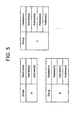
- FIG. 2 is an explanatory diagram showing a state of transmitting and receiving packets through the proxy server 3.
- the proxy server 3 When receiving a multicast packet from a terminal 1, the proxy server 3 transmits unicast packets to the addresses of terminals 1 belonging to a group corresponding to the multicast packet.
- the proxy server 3 has a table for managing, for each group of multicast communication, the addresses of terminals 1 belonging to the group.
- “Group” included in the table shown in FIG. 2 represents a group of multicast communication.
- "Destination” represents the address of each terminal belonging to the group of multicast communication, i.e., the destination address.
- the proxy server 3 refers to the table to search for the addresses of terminals 1 belonging to the group corresponding to the multicast packet received.
- a communication device such as a router
- an operator can avoid complicated network designing such as the placement and setting of a communication device that enables multicast communication.
- the control apparatus 4 has the function of controlling packet transfer in the network 2 so that the multicast packet transmitted by the terminal 1 will reach the proxy server 3.
- the control apparatus 4 controls, for example, a routing table of a router in the network 2 to perform control to make the multicast packet reach the proxy server 3.
- the control apparatus 4 controls the routing table of the router existing in the network 2 so that a packet with an address including a multicast address will be transferred to the proxy server 3.
- the control apparatus 4 may control, for example, packet transfer in the network 2 so that a multicast packet transmitted by a terminal 1 to the proxy server 3 will reach the proxy server 3.
- the control apparatus 4 controls the routing table of the router in the network 2 to perform control to make the packet addressed to the proxy server 3 reach the proxy server 3.
- the control apparatus 4 may also have the function of notifying each terminal 1 of the address of the proxy server 3, respectively.
- FIG. 3 is a sequence diagram showing an example of the operation of the communication system in the first exemplary embodiment.
- a terminal 1 transmits a multicast packet (step S10, step S11).
- the control apparatus 4 controls the network 2 to make the multicast packet reach the proxy server 3.
- the proxy server 3 that received the multicast packet determines the destination addresses of terminals 1 belonging to the group of the multicast packet (step S12, step S13).
- the proxy server 3 transmits a unicast packet to each of the terminals belonging to the group of the received multicast packet, respectively (step S14, step S15).
- the proxy server 3 in the exemplary embodiment transmits unicast packets to the addresses of terminals 1 belonging to a group corresponding to the multicast packet.
- the control apparatus 4 for controlling the network controls the network so that multicast packets will be aggregated on the proxy server 3. This enables multicast communication without complicated network designing such as the placement and setting of a communication device that enables multicast communication. This enables multicast communication at a low management cost in a network where there exists a device that does not have a function corresponding to multicast communication. Further, since multicast packets transmitted from communication terminals are aggregated on the proxy server, the proxy server can perform centralized control of the execution of unicast communication based on multicast communication.
- FIG. 4 is a block diagram showing an example of the configuration of the proxy server 3.
- the proxy server 3 includes a multicast reception unit 30, a destination determination unit 31, a management DB (Data Base) 32, and a unicast transmission unit 33.
- the multicast reception unit 30 receives a multicast packet through the network 2.
- the destination determination unit 31 determines destination addresses belonging to a group corresponding to the multicast packet received.
- the destination determination unit 31 refers to information stored in the management DB 32 to determine the destination addresses.
- FIG. 5 is an explanatory diagram showing an example of the structure of the information stored in the management DB 32.
- the management DB 32 manages, for each group of multicast communication, destination addresses belonging to the group.
- the unicast transmission unit 33 transmits a unicast packet to each address determined by the destination determination unit 31, respectively.
- the multicast reception unit 30, the destination determination unit 31, and the unicast transmission unit 33 are implemented, for example, by a computer operating according to a program. In this case, it is only necessary for a CPU provided in the proxy server 3 to read the program and operate as the multicast reception unit 30, the destination determination unit 31, and the unicast transmission unit 33 according to the program.
- the multicast reception unit 30, the destination determination unit 31, and the unicast transmission unit 33 may also be implemented by separate hardware.
- the management DB 32 is realized by a storage device such as a memory provided in the proxy server 3.
- FIG. 6 is a schematic diagram showing an example of the headers of packets transmitted and received by the proxy server 3 in the second exemplary embodiment.
- FIG. 6 shows a multicast packet and unicast packets generated from the multicast packet.
- the destination determination unit 31 determines a group corresponding to the multicast packet.
- "Multicast Address (Group: A)” included in FIG. 6 indicates that a group corresponding to the destination addresses of the multicast packet is "Group A.”
- "Source Address” included in FIG. 6 represents the source address of the packet. In the example shown in FIG. 6 , the destination determination unit 31 determines, from the destination addresses, that the group corresponding to the packet is "Group A.”
- the destination determination unit 31 refers to the management DB 32 to search for unicast addresses corresponding to "Group A.”
- the unicast addresses corresponding to "Group A” are "Address(a)” and “Address(b).” Therefore, the destination determination unit 31 determines that the unicast addresses corresponding to "Group A” are "Address(a)” and "Address(b).”
- the unicast transmission unit 33 transmits packets to "Address(a)" and "Address(b)" as the destination addresses, respectively.
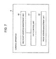
- FIG. 7 is a block diagram showing an example of the configuration of the control apparatus 4.
- the control apparatus 4 includes a multicast address management unit 40 and a path control unit 41.
- the path control unit 41 controls a communication device (e.g., a router or a switch) existing in the network 2 to control packet transfer so that the multicast packet will reach the proxy server 3.
- a communication device e.g., a router or a switch
- the path control unit 41 refers to the multicast address management unit 40 to control the network 2.
- the multicast address management unit 40 manages an address system of multicast addresses used in the communication system.
- an address range represented by "224.0.0.0/4" is generally used.
- the range "224.0.0.0/4" represents addresses in a range where the starting address is "224.0.0.0" and the ending address is "239.255.255.255.”
- the multicast address management unit 40 stores "224.0.0.0/4" as the address range used in the communication system.
- the path control unit 41 instructs the communication device of the network 2 to transfer the received packet to the proxy server 3.
- the path control unit 41 may notify the terminals 1 of the address of the proxy server 3.
- a terminal 1 notified of the address of the proxy server 3 adds, to the packet addressed to the proxy server 3, information indicative of a group of multicast communication, and transmits it to the network 2.
- the path control unit 41 controls the communication device of the network 2 beforehand so that the packet addressed to the proxy server 3 will reach the proxy server 3.
- the control apparatus 4 may also have the function of managing the proxy server 3.
- the control apparatus 4 has a proxy server management unit 42 as the function of managing the proxy server 3.
- the operator of the communication system configures information on the management DB 32 illustrated in FIG. 5 through the proxy server management unit 42.
- the multicast address management unit 40, the path control unit 41, and the proxy server management unit 42 are implemented by a computer operating, for example, according to a transfer control program. In this case, it is only necessary for a CPU provided in the control apparatus 4 to read the transfer control program and operate as the multicast address management unit 40, the path control unit 41, and the proxy server management unit 42 according to the program.
- the multicast address management unit 40, the path control unit 41, and the proxy server management unit 42 may also be realized by separate hardware.
- the third exemplary embodiment a configuration example of making the proxy server 3 redundant will be described.
- the third exemplary embodiment can be combined with any of the aforementioned exemplary embodiments.
- the proxy server 3 is made redundant to enable a reduction in the load on the proxy server 3.
- FIG. 8 is a block diagram showing an example of the configuration of a communication system in the third exemplary embodiment.
- the multicast packets transmitted from the terminals 1 are distributed to multiple redundant proxy servers 3.
- a server cluster i.e., the multiple redundant proxy servers 3 share the management DB 32 to enable both the redundant load distribution and the reduction in management cost.
- control apparatus 4 controls packet transfer in the network 2 so that multicast packets transmitted by terminals 1 will reach the multiple redundant proxy servers 3 in a distributed manner.
- the control apparatus 4 divides an address range of multicast addresses, and assign a proxy server 3 corresponding to multicast addresses in each divided address range. For example, the control apparatus 4 divides the address range of "224.0.0.0/4" into address ranges (A), (B), and (C), and assigns a corresponding proxy server 3 to each address range. For example, the control apparatus 4 assigns a proxy server 3 corresponding to each address range in round-robin fashion. For example, the control apparatus 4 controls the communication device of the network 2 to change the transfer destination of multicast packets in each divided address range. For example, when receiving multicast packets belonging to the address range (A), the control apparatus 4 instructs the communication device to transfer the received multicast packets to the proxy server 3 assigned to the address range (A).
- system configuration in the third exemplary embodiment may be such that a load balancer, not shown in FIG. 8 , collectively receives the multicast packets and sorts the packets into respective proxy servers 3.
- the fourth exemplary embodiment an example where terminals to be taken care of are assigned to each of multiple proxy servers 3 will be described.
- the multiple proxy servers 3 share the responsibility for the terminals to enable a reduction in the load on the proxy servers 3.
- the fourth exemplary embodiment can be combined with any of the aforementioned exemplary embodiments.
- FIG. 9 is a block diagram showing an example of the configuration of a communication system in the fourth exemplary embodiment.
- terminals to be taken care of are assigned to each of proxy server 3-1, proxy server 3-2, and proxy server 3-3, respectively.
- Each proxy server handles only multicast packets transmitted from terminals to be taken care of.
- respective proxy servers share the management DB 32 to reduce the cost of managing the correspondence relationship between a group of multicast communication and unicast addresses corresponding to the group.
- each proxy server 3 and the structure of information stored in the management DB 32 are the same as those in the aforementioned exemplary embodiments, detailed description thereof will be omitted.
- control apparatus 4 determines terminals taken care of by each proxy server.
- the control apparatus 4 controls the communication device of the network 2 so that a multicast packet transmitted from each terminal will be transferred to a proxy server having charge of the terminal from which the packet has been transmitted.
- control apparatus 4 controls the communication device to change the packet transfer destination according to the source address of the multicast packet received.
- a load balancer may collectively receive multicast packets and sort the packets into respective proxy servers having charge of terminals corresponding to source addresses according to the source addresses of the received packets.
- TEP Tannel EndPoint
- VXLAN Virtual Extensible LAN
- ARP Address Resolution Protocol
- the present invention can also be applied to a technology for performing multicast communication on an overlay network.
- FIG. 10 is a block diagram showing an example of the configuration of a communication system in the fifth exemplary embodiment.
- a terminal 1 communicates with an overlay network 20 through a TEP 5.
- the TEP 5 encapsulates a packet transmitted from the terminal 1 and transmits it to the overlay network 20. Further, the TEP 5 decapsulates a packet addressed to a terminal 1 and transmitted from the overlay network 20, and transmits it to the terminal 1.
- a multicast packet transmitted from a TEP 5 is aggregated on the proxy server 3.
- the proxy server 3 transmits unicast packets to each of TEPs 5 belonging to a group of the multicast packet received.
- control apparatus 4 controls the overlay network 20 so that the multicast packet transmitted from the TEP 5 will reach the proxy server 3 by the method described in the aforementioned exemplary embodiments.
- FIG. 11 is a schematic diagram showing an example of the headers of packets to be transmitted and received by the proxy server 3 in the fifth exemplary embodiment.
- FIG. 11 shows a multicast packet transmitted from the TEP 5 and unicast packets generated from the multicast packet.
- Outer included in FIG. 11 represents information added to the packet in encapsulation processing by the TEP 5.
- Inner included in FIG. 11 represents header information before the encapsulation by the TEP 5.
- Dest Add included in FIG. 11 represents a destination address of the packet.
- Src Add included in FIG. 11 represents a source address of the packet.
- the proxy server 3 receives a packet including a multicast address in the destination address of the Outer header.
- a group corresponding to the multicast address is "Group A.”
- the destination address of the Outer header may be the address of the proxy server 3.
- the proxy server 3 determines a group from the packet received.
- the proxy server 3 transmits unicast packets to the addresses of TEPs 5 belonging to the determined group, respectively.
- the addresses of the TEPs 5 belonging to the group are "Address (a)" and "Address (b)."
- the present invention is not limited to each of the exemplary embodiments mentioned above.
- the present invention can be carried out based on any modification, substitution, or adjustment of each exemplary embodiment.
- the present invention can also be carried out by arbitrarily combining respective exemplary embodiments.
- the present invention includes various modifications and alterations that can be realized according to the entire disclosure and technical ideas of the specification.
Abstract
Description
- The present invention relates to a communication system, a control apparatus, a communication control method in the communication system, and a transfer control method and program in the control apparatus, and to an information processing apparatus for performing multicast communication.
- In a computer network, there exists a technology called multicast communication for transmitting packets to multiple terminals belonging to a predetermined group. In the multicast communication, a multicast address including an identifier of a group to which multiple terminals as packet destinations belong is used.
- When receiving a multicast packet, a communication device (a router or the like) transfers the packet to terminals belonging to a group corresponding to the multicast packet. In order to enable multicast communication, the communication device (the router or the like) is required to manage an identifier of the group, and packet transfer destinations corresponding to the identifier. Since the terminals belonging to the group are dynamically changed, the communication device is required to manage an identifier of the group and transfer destinations corresponding to the identifier routinely.
- In order to perform multicast communication, a communication device on a network is required to have the above management function. Therefore, in a network where there exists any communication device that does not have the above management function, there is a possibility that the multicast communication is not performed properly.
- Patent Literature (PTL) 1 discloses a technique for enabling pseudo multicast communication even in a network where there exists a communication device that does not have a function of performing multicast communication. A relay station described in
PTL 1 manages a group of multicast communication, and destination addresses of terminals belonging to the group. When performing multicast communication, the relay station transmits a packet to the destination address of each terminal belonging to the group through unicast communication. Since the packet is transmitted by multiple unicast communications to the respective destination addresses of the terminals, the technique described inPTL 1 can be applied to a network where there exists a device that does not have a function of performing multicast communication to enable pseudo multicast communication in the network. -
PTL 2 describes a technique for reducing the load on multicast processing in the wide-area Ethernet (registered trademark) composed of a core device such as a switch or a router, and multiple edge devices such as switches or routers directly or indirectly connected to the core device. In the technique described inPTL 2, when the load on the core device is high, a multicast source edge device transmits multicast frames by unicast as the number of required destination edge devices, rather than by multicast, to reduce the load on the core device. -
- PTL 1: Japanese Patent Application Laid-Open No.
2005-197844 - PTL 2: Japanese Patent Application Laid-Open No.
2011-217038 - The technique described in
PTL 1 is such that each of relay stations manages, in a decentralized manner, a table in which a correspondence relationship between a group of multicast communication and destination addresses of terminals belonging to the group is listed to perform pseudo multicast communication. Since the table is managed in a decentralized manner, respective relay stations need to communicate with each other to exchange table information. Therefore, there arises a problem of the management cost for respective relay stations to manage tables for multicast communication in a decentralized manner. - It is an exemplary object of the present invention to provide a communication system, a control apparatus, a communication control method in the communication system, and a transfer control method and program in the control apparatus, which enable multicast communication at a low management cost in a network where there exists a device that does not have a function corresponding to the multicast communication.
- The communication system according to the present invention is a communication system in which multiple communication terminals communicate through a network, including: a control apparatus which controls packet transfer in the network; and a proxy server which receives a multicast packet transmitted from each of communication terminals and transmits unicast packets to communication terminals belonging to a group corresponding to the multicast packet, respectively, wherein the control apparatus controls packet transfer in the network so that the multicast packet transmitted by the communication terminal will be transferred to the proxy server.
- The control apparatus according to the present invention is a control apparatus in a communication system in which multiple communication terminals communicate through a network, wherein the control apparatus controls packet transfer in the network so that a multicast packet transmitted by each of communication terminals will be transferred to a proxy server for transmitting a unicast packet to each of communication terminals belonging to a group corresponding to the multicast packet, respectively.
- The communication control method according to the present invention is a communication control method in a communication system in which multiple communication terminals communicate through a network, wherein a control apparatus controls packet transfer in the network so that a multicast packet transmitted by each of communication terminals will be transferred to a proxy server, and the proxy server receives the multicast packet transmitted from the communication terminal and transmits a unicast packet to each of communication terminals belonging to a group corresponding to the multicast packet, respectively.
- The transfer control method according to the present invention is a transfer control method in a control apparatus applied to a communication system in which multiple communication terminals communicate through a network, wherein packet transfer in the network is so controlled that a multicast packet transmitted by each of communication terminals will be transferred to a proxy server for transmitting a unicast packet to each of communication terminals belonging to a group corresponding to the multicast packet, respectively.
- The transfer control program according to the present invention is a transfer control program in a communication system in which multiple communication terminals communicate through a network, the program causing a computer to execute a process of controlling packet transfer in the network so that a multicast packet transmitted by each of communication terminals will be transferred to a proxy server for transmitting a unicast packet to each of communication terminals belonging to a group corresponding to the multicast packet, respectively.
- The present invention has the effect of enabling multicast communication at a low management cost in a network where there exists a device that does not have a function corresponding to multicast communication.
-
- [
FIG. 1 ] It depicts a block diagram showing an example of the configuration of a communication system in a first exemplary embodiment. - [
FIG. 2 ] It depicts an explanatory diagram showing a state of transmitting and receiving packets through a proxy server. - [
FIG. 3 ] It depicts a sequence diagram showing an example of the operation of the communication system in the first exemplary embodiment. - [
FIG. 4 ] It depicts a block diagram showing an example of the configuration of the proxy server. - [
FIG. 5 ] It depicts an explanatory diagram showing an example of the structure of information stored in a management DB. - [
FIG. 6 ] It depicts a schematic diagram showing an example of the header s of packets transmitted and received by a proxy server in a second exemplary embodiment. - [
FIG. 7 ] It depicts a block diagram showing an example of the configuration of a control apparatus. - [
FIG. 8 ] It depicts a block diagram showing an example of the configuration of a communication system in a third exemplary embodiment. - [
FIG. 9 ] It depicts a block diagram showing an example of the configuration of a communication system in a fourth exemplary embodiment. - [
FIG. 10 ] It depicts a block diagram showing an example of the configuration of a communication system in a fifth exemplary embodiment. - [
FIG. 11 ] It depicts a schematic diagram showing an example of the headers of packets transmitted and received by a proxy server in the fifth exemplary embodiment. - A first exemplary embodiment of the present invention will be described below with reference to the accompanying drawings.
- In the first exemplary embodiment, multicast packets transmitted from communication terminals are aggregated on a proxy server. A control apparatus for controlling a network controls the network to aggregate multicast packets on the proxy server. This enables a predetermined proxy server to perform centralized control of the execution of unicast communication based on multicast communication.
-
FIG. 1 is a block diagram showing an example of the configuration of a communication system in a first exemplary embodiment. The communication system in the exemplary embodiment includes aproxy server 3 and acontrol apparatus 4. - Each of
multiple terminals 1 is communicable with theproxy server 3 through anetwork 2. Thecontrol apparatus 4 is connected to thenetwork 2. - The
terminals 1 have the function of transmitting a multicast packet to perform multicast communication. - The
proxy server 3 has the function of, based on a multicast packet received from aterminal 1, transmitting packets through unicast communication toterminals 1 corresponding to a group of the multicast packet. In other words, theproxy server 3 has the function of performing pseudo multicast communication on behalf of a communication device such as a router. -
FIG. 2 is an explanatory diagram showing a state of transmitting and receiving packets through theproxy server 3. - When receiving a multicast packet from a
terminal 1, theproxy server 3 transmits unicast packets to the addresses ofterminals 1 belonging to a group corresponding to the multicast packet. For example, as shown inFIG. 2 , theproxy server 3 has a table for managing, for each group of multicast communication, the addresses ofterminals 1 belonging to the group. "Group" included in the table shown inFIG. 2 represents a group of multicast communication. Further, "Destination" represents the address of each terminal belonging to the group of multicast communication, i.e., the destination address. In the example shown inFIG. 2 , "Address(a)" and "Address(b)" are registered as the addresses of terminals belonging to "Group A." For example, theproxy server 3 refers to the table to search for the addresses ofterminals 1 belonging to the group corresponding to the multicast packet received. - This enables the
proxy server 3 to perform multicast communication without placing, in thenetwork 2, a communication device (such as a router) adapted to multicast communication. Thus, an operator can avoid complicated network designing such as the placement and setting of a communication device that enables multicast communication. - The
control apparatus 4 has the function of controlling packet transfer in thenetwork 2 so that the multicast packet transmitted by theterminal 1 will reach theproxy server 3. - The
control apparatus 4 controls, for example, a routing table of a router in thenetwork 2 to perform control to make the multicast packet reach theproxy server 3. For example, thecontrol apparatus 4 controls the routing table of the router existing in thenetwork 2 so that a packet with an address including a multicast address will be transferred to theproxy server 3. - The
control apparatus 4 may control, for example, packet transfer in thenetwork 2 so that a multicast packet transmitted by aterminal 1 to theproxy server 3 will reach theproxy server 3. For example, thecontrol apparatus 4 controls the routing table of the router in thenetwork 2 to perform control to make the packet addressed to theproxy server 3 reach theproxy server 3. Thecontrol apparatus 4 may also have the function of notifying eachterminal 1 of the address of theproxy server 3, respectively. - Next, the operation of the exemplary embodiment will be described.
-
FIG. 3 is a sequence diagram showing an example of the operation of the communication system in the first exemplary embodiment. - A
terminal 1 transmits a multicast packet (step S10, step S11). Thecontrol apparatus 4 controls thenetwork 2 to make the multicast packet reach theproxy server 3. - The
proxy server 3 that received the multicast packet determines the destination addresses ofterminals 1 belonging to the group of the multicast packet (step S12, step S13). - The
proxy server 3 transmits a unicast packet to each of the terminals belonging to the group of the received multicast packet, respectively (step S14, step S15). - As described above, when receiving a multicast packet from a
terminal 1, theproxy server 3 in the exemplary embodiment transmits unicast packets to the addresses ofterminals 1 belonging to a group corresponding to the multicast packet. Further, thecontrol apparatus 4 for controlling the network controls the network so that multicast packets will be aggregated on theproxy server 3. This enables multicast communication without complicated network designing such as the placement and setting of a communication device that enables multicast communication. This enables multicast communication at a low management cost in a network where there exists a device that does not have a function corresponding to multicast communication. Further, since multicast packets transmitted from communication terminals are aggregated on the proxy server, the proxy server can perform centralized control of the execution of unicast communication based on multicast communication. - A second exemplary embodiment of the present invention will be described below with reference to the accompanying drawings.
- In the second exemplary embodiment, configuration examples of the
proxy server 3 and thecontrol apparatus 4 will be described. -
FIG. 4 is a block diagram showing an example of the configuration of theproxy server 3. - The
proxy server 3 includes amulticast reception unit 30, adestination determination unit 31, a management DB (Data Base) 32, and aunicast transmission unit 33. - The
multicast reception unit 30 receives a multicast packet through thenetwork 2. - The
destination determination unit 31 determines destination addresses belonging to a group corresponding to the multicast packet received. Thedestination determination unit 31 refers to information stored in themanagement DB 32 to determine the destination addresses. -
FIG. 5 is an explanatory diagram showing an example of the structure of the information stored in themanagement DB 32. - For example, the
management DB 32 manages, for each group of multicast communication, destination addresses belonging to the group. - The
unicast transmission unit 33 transmits a unicast packet to each address determined by thedestination determination unit 31, respectively. - Note that the
multicast reception unit 30, thedestination determination unit 31, and theunicast transmission unit 33 are implemented, for example, by a computer operating according to a program. In this case, it is only necessary for a CPU provided in theproxy server 3 to read the program and operate as themulticast reception unit 30, thedestination determination unit 31, and theunicast transmission unit 33 according to the program. Themulticast reception unit 30, thedestination determination unit 31, and theunicast transmission unit 33 may also be implemented by separate hardware. - The
management DB 32 is realized by a storage device such as a memory provided in theproxy server 3. -
FIG. 6 is a schematic diagram showing an example of the headers of packets transmitted and received by theproxy server 3 in the second exemplary embodiment.FIG. 6 shows a multicast packet and unicast packets generated from the multicast packet. - Based on the destination addresses of a multicast packet received, the
destination determination unit 31 determines a group corresponding to the multicast packet. "Multicast Address (Group: A)" included inFIG. 6 indicates that a group corresponding to the destination addresses of the multicast packet is "Group A." "Source Address" included inFIG. 6 represents the source address of the packet. In the example shown inFIG. 6 , thedestination determination unit 31 determines, from the destination addresses, that the group corresponding to the packet is "Group A." - The
destination determination unit 31 refers to themanagement DB 32 to search for unicast addresses corresponding to "Group A." In the example shown inFIG. 5 , the unicast addresses corresponding to "Group A" are "Address(a)" and "Address(b)." Therefore, thedestination determination unit 31 determines that the unicast addresses corresponding to "Group A" are "Address(a)" and "Address(b)." - The
unicast transmission unit 33 transmits packets to "Address(a)" and "Address(b)" as the destination addresses, respectively. -
FIG. 7 is a block diagram showing an example of the configuration of thecontrol apparatus 4. - The
control apparatus 4 includes a multicastaddress management unit 40 and apath control unit 41. - The path control
unit 41 controls a communication device (e.g., a router or a switch) existing in thenetwork 2 to control packet transfer so that the multicast packet will reach theproxy server 3. - For example, the path control
unit 41 refers to the multicastaddress management unit 40 to control thenetwork 2. - For example, the multicast
address management unit 40 manages an address system of multicast addresses used in the communication system. As the multicast addresses, an address range represented by "224.0.0.0/4" is generally used. The range "224.0.0.0/4" represents addresses in a range where the starting address is "224.0.0.0" and the ending address is "239.255.255.255." For example, the multicastaddress management unit 40 stores "224.0.0.0/4" as the address range used in the communication system. - For example, when the destination address of a received packet falls within the address range of "224.0.0.0/4," the path control
unit 41 instructs the communication device of thenetwork 2 to transfer the received packet to theproxy server 3. - Further, for example, the path control
unit 41 may notify theterminals 1 of the address of theproxy server 3. Aterminal 1 notified of the address of theproxy server 3 adds, to the packet addressed to theproxy server 3, information indicative of a group of multicast communication, and transmits it to thenetwork 2. The path controlunit 41 controls the communication device of thenetwork 2 beforehand so that the packet addressed to theproxy server 3 will reach theproxy server 3. - The
control apparatus 4 may also have the function of managing theproxy server 3. For example, thecontrol apparatus 4 has a proxyserver management unit 42 as the function of managing theproxy server 3. - For example, the operator of the communication system configures information on the
management DB 32 illustrated inFIG. 5 through the proxyserver management unit 42. - Note that the multicast
address management unit 40, the path controlunit 41, and the proxyserver management unit 42 are implemented by a computer operating, for example, according to a transfer control program. In this case, it is only necessary for a CPU provided in thecontrol apparatus 4 to read the transfer control program and operate as the multicastaddress management unit 40, the path controlunit 41, and the proxyserver management unit 42 according to the program. The multicastaddress management unit 40, the path controlunit 41, and the proxyserver management unit 42 may also be realized by separate hardware. - A third exemplary embodiment of the present invention will be described below with reference to the accompanying drawings.
- In the third exemplary embodiment, a configuration example of making the
proxy server 3 redundant will be described. The third exemplary embodiment can be combined with any of the aforementioned exemplary embodiments. - When multicast packets transmitted from
respective terminals 1 are aggregated on theproxy server 3, an increase in the load on theproxy server 3 is a concern. In the third exemplary embodiment, theproxy server 3 is made redundant to enable a reduction in the load on theproxy server 3. -
FIG. 8 is a block diagram showing an example of the configuration of a communication system in the third exemplary embodiment. - The multicast packets transmitted from the
terminals 1 are distributed to multipleredundant proxy servers 3. On the other hand, if the management of the correspondence relationship between a group of multicast communication and unicast addresses corresponding to the group is distributed to themultiple proxy servers 3, an increase in management cost will be a concern. In the third exemplary embodiment, a server cluster, i.e., the multipleredundant proxy servers 3 share themanagement DB 32 to enable both the redundant load distribution and the reduction in management cost. - Since the configuration of the
proxy server 3 and the structure of information stored in themanagement DB 32 are the same as those in the aforementioned exemplary embodiments, detailed description thereof will be omitted. - For example, the
control apparatus 4 controls packet transfer in thenetwork 2 so that multicast packets transmitted byterminals 1 will reach the multipleredundant proxy servers 3 in a distributed manner. - For example, the
control apparatus 4 divides an address range of multicast addresses, and assign aproxy server 3 corresponding to multicast addresses in each divided address range. For example, thecontrol apparatus 4 divides the address range of "224.0.0.0/4" into address ranges (A), (B), and (C), and assigns acorresponding proxy server 3 to each address range. For example, thecontrol apparatus 4 assigns aproxy server 3 corresponding to each address range in round-robin fashion. For example, thecontrol apparatus 4 controls the communication device of thenetwork 2 to change the transfer destination of multicast packets in each divided address range. For example, when receiving multicast packets belonging to the address range (A), thecontrol apparatus 4 instructs the communication device to transfer the received multicast packets to theproxy server 3 assigned to the address range (A). - Note that the system configuration in the third exemplary embodiment may be such that a load balancer, not shown in
FIG. 8 , collectively receives the multicast packets and sorts the packets intorespective proxy servers 3. - A fourth exemplary embodiment of the present invention will be described below with reference to the accompanying drawings.
- In the fourth exemplary embodiment, an example where terminals to be taken care of are assigned to each of
multiple proxy servers 3 will be described. Themultiple proxy servers 3 share the responsibility for the terminals to enable a reduction in the load on theproxy servers 3. - The fourth exemplary embodiment can be combined with any of the aforementioned exemplary embodiments.
-
FIG. 9 is a block diagram showing an example of the configuration of a communication system in the fourth exemplary embodiment. - In the example shown in
FIG. 9 , terminals to be taken care of are assigned to each of proxy server 3-1, proxy server 3-2, and proxy server 3-3, respectively. Each proxy server handles only multicast packets transmitted from terminals to be taken care of. - Like in the third exemplary embodiment, respective proxy servers share the
management DB 32 to reduce the cost of managing the correspondence relationship between a group of multicast communication and unicast addresses corresponding to the group. - Since the configuration of each
proxy server 3 and the structure of information stored in themanagement DB 32 are the same as those in the aforementioned exemplary embodiments, detailed description thereof will be omitted. - For example, the
control apparatus 4 determines terminals taken care of by each proxy server. Thecontrol apparatus 4 controls the communication device of thenetwork 2 so that a multicast packet transmitted from each terminal will be transferred to a proxy server having charge of the terminal from which the packet has been transmitted. - For example, the
control apparatus 4 controls the communication device to change the packet transfer destination according to the source address of the multicast packet received. - Note that a load balancer, not shown in
FIG. 9 , may collectively receive multicast packets and sort the packets into respective proxy servers having charge of terminals corresponding to source addresses according to the source addresses of the received packets. - A fifth exemplary embodiment of the present invention will be described below with reference to the accompanying drawings.
- In the fifth exemplary embodiment, an example where a TEP (Tunnel EndPoint) transmits multicast packets in an overlay network will be described. The fifth exemplary embodiment can be combined with any of the aforementioned exemplary embodiments.
- For example, VXLAN (Virtual Extensible LAN) as a technology for overlaying a
layer 2 network on alayer 3 network uses multicast communication when transmitting an ARP (Address Resolution Protocol) request. According to the fifth exemplary embodiment, the present invention can also be applied to a technology for performing multicast communication on an overlay network. -
FIG. 10 is a block diagram showing an example of the configuration of a communication system in the fifth exemplary embodiment. - A
terminal 1 communicates with anoverlay network 20 through aTEP 5. For example, theTEP 5 encapsulates a packet transmitted from theterminal 1 and transmits it to theoverlay network 20. Further, theTEP 5 decapsulates a packet addressed to aterminal 1 and transmitted from theoverlay network 20, and transmits it to theterminal 1. - Since the other parts of the configuration are the same as those in the aforementioned exemplary embodiments, detailed description thereof will be omitted.
- A multicast packet transmitted from a
TEP 5 is aggregated on theproxy server 3. Theproxy server 3 transmits unicast packets to each ofTEPs 5 belonging to a group of the multicast packet received. - For example, the
control apparatus 4 controls theoverlay network 20 so that the multicast packet transmitted from theTEP 5 will reach theproxy server 3 by the method described in the aforementioned exemplary embodiments. -
FIG. 11 is a schematic diagram showing an example of the headers of packets to be transmitted and received by theproxy server 3 in the fifth exemplary embodiment.FIG. 11 shows a multicast packet transmitted from theTEP 5 and unicast packets generated from the multicast packet. - "Outer" included in
FIG. 11 represents information added to the packet in encapsulation processing by theTEP 5. "Inner" included inFIG. 11 represents header information before the encapsulation by theTEP 5. "Dest Add" included inFIG. 11 represents a destination address of the packet. "Src Add" included inFIG. 11 represents a source address of the packet. - The
proxy server 3 receives a packet including a multicast address in the destination address of the Outer header. In the example shown inFIG. 11 , it is assumed that a group corresponding to the multicast address is "Group A." Note that the destination address of the Outer header may be the address of theproxy server 3. - The
proxy server 3 determines a group from the packet received. Theproxy server 3 transmits unicast packets to the addresses ofTEPs 5 belonging to the determined group, respectively. In the example shown inFIG. 11 , the addresses of theTEPs 5 belonging to the group are "Address (a)" and "Address (b)." - While the exemplary embodiments of the present invention has been described, the present invention is not limited to each of the exemplary embodiments mentioned above. The present invention can be carried out based on any modification, substitution, or adjustment of each exemplary embodiment. The present invention can also be carried out by arbitrarily combining respective exemplary embodiments. In other words, the present invention includes various modifications and alterations that can be realized according to the entire disclosure and technical ideas of the specification.
- This application is based upon and claims the benefit of priority from Japanese patent application No.
2012-266598, filed on December 5th, 2012 -
- 1
- terminal
- 2
- network
- 20
- overlay network
- 3
- proxy server
- 30
- multicast reception unit
- 31
- destination determination unit
- 32
- management DB
- 33
- unicast transmission unit
- 4
- control apparatus
- 40
- multicast address management unit
- 41
- path control unit
- 42
- proxy server management unit
- 5
- TEP
Claims (19)
- A communication system in which a plurality of communication terminals communicate through a network, comprising:a control apparatus which controls packet transfer in the network; anda proxy server which receives a multicast packet transmitted from each of the communication terminals and transmits unicast packets to communication terminals belonging to a group corresponding to the multicast packet, respectively,wherein the control apparatus controls packet transfer in the network so that the multicast packet transmitted by the communication terminal will be transferred to the proxy server.
- The communication system according to claim 1, wherein the control apparatus controls packet transfer in the network so that multicast packets transmitted by the plurality of communication terminals will be aggregated on the proxy server.
- The communication system according to claim 1 or 2, wherein the proxy server performs centralized management of a correspondence relationship between a multicast communication group and unicast addresses corresponding to the group.
- The communication system according to any one of claims 1 to 3, wherein
the communication system includes a plurality of proxy servers, and
the control apparatus controls packet transfer in the network so that a multicast packet transmitted from a communication terminal will be transferred to a proxy server corresponding to the communication terminal among the plurality of proxy servers. - The communication system according to any one of claims 1 to 4, wherein
the communication system includes a plurality of proxy servers,
the plurality of proxy servers share a database in which a correspondence relationship between a multicast communication group and unicast addresses corresponding to the group is stored, and
each of the proxy servers searches the database for unicast addresses in a group corresponding to a multicast packet received. - A control apparatus in a communication system in which a plurality of communication terminals communicate through a network,
wherein the control apparatus controls packet transfer in the network so that a multicast packet transmitted by each of the communication terminals will be transferred to a proxy server for transmitting a unicast packet to each of communication terminals belonging to a group corresponding to the multicast packet, respectively. - The control apparatus according to claim 6, wherein the control apparatus controls packet transfer in the network so that multicast packets transmitted by the plurality of communication terminals will be aggregated on the proxy server.
- The control apparatus according to claim 6 or 7, wherein the control apparatus controls packet transfer in the network so that a multicast packet transmitted from a communication terminal will be transferred to a proxy server corresponding to the communication terminal among a plurality of proxy servers.
- A communication control method in a communication system in which a plurality of communication terminals communicate through a network, wherein
a control apparatus controls packet transfer in the network so that a multicast packet transmitted by each of the communication terminals will be transferred to a proxy server, and
the proxy server receives the multicast packet transmitted from the communication terminal and transmits a unicast packet to each of communication terminals belonging to a group corresponding to the multicast packet, respectively. - The communication control method according to claim 9, wherein the control apparatus controls packet transfer in the network so that multicast packets transmitted by the plurality of communication terminals will be aggregated on the proxy server.
- The communication control method according to claim 9 or 10, wherein the proxy server performs centralized management of a correspondence relationship between a multicast communication group and unicast addresses corresponding to the group.
- The communication control method according to any one of claims 9 to 11, wherein the control apparatus controls packet transfer in the network so that a multicast packet transmitted from a communication terminal will be transferred to a proxy server corresponding to the communication terminal among a plurality of proxy servers.
- The communication control method according to any one of claims 9 to 12, wherein
a plurality of proxy servers share a database in which a correspondence relationship between a multicast communication group and unicast addresses corresponding to the group is stored, and
each of the proxy servers searches the database for unicast addresses in a group corresponding to a multicast packet received. - A transfer control method in a control apparatus applied to a communication system in which a plurality of communication terminals communicate through a network, wherein
packet transfer in the network is so controlled that a multicast packet transmitted by each of the communication terminals will be transferred to a proxy server for transmitting a unicast packet to each of communication terminals belonging to a group corresponding to the multicast packet, respectively. - The transfer control method according to claim 14, wherein packet transfer by the network is so controlled that multicast packets transmitted by the plurality of communication terminals will be aggregated on the proxy server.
- The transfer control method according to claim 14 or 15, wherein packet transfer in the network is so controlled that a multicast packet transmitted from a communication terminal will be transferred to a proxy server corresponding to the communication terminal among a plurality of proxy servers.
- A transfer control program in a communication system in which a plurality of communication terminals communicate through a network, the program causing a computer to execute
a process of controlling packet transfer in the network so that a multicast packet transmitted by each of the communication terminals will be transferred to a proxy server for transmitting a unicast packet to each of communication terminals belonging to a group corresponding to the multicast packet, respectively. - The transfer control program according to claim 17, further causing the computer to execute
a process of controlling packet transfer in the network so that multicast packets transmitted by the plurality of communication terminals will be aggregated on the proxy server. - The transfer control program according to claim 17 or 18, further causing the computer to execute
a process of controlling packet transfer in the network so that a multicast packet transmitted from a communication terminal will be transferred to a proxy server corresponding to the communication terminal among a plurality of proxy servers.
Applications Claiming Priority (2)
| Application Number | Priority Date | Filing Date | Title |
|---|---|---|---|
| JP2012266598 | 2012-12-05 | ||
| PCT/JP2013/006778 WO2014087591A1 (en) | 2012-12-05 | 2013-11-19 | Communication system, control apparatus, communication control method, transfer control method, and transfer control program |
Publications (2)
| Publication Number | Publication Date |
|---|---|
| EP2930893A1 true EP2930893A1 (en) | 2015-10-14 |
| EP2930893A4 EP2930893A4 (en) | 2016-05-18 |
Family
ID=50883033
Family Applications (1)
| Application Number | Title | Priority Date | Filing Date |
|---|---|---|---|
| EP13859758.8A Withdrawn EP2930893A4 (en) | 2012-12-05 | 2013-11-19 | Communication system, control apparatus, communication control method, transfer control method, and transfer control program |
Country Status (5)
| Country | Link |
|---|---|
| US (1) | US20150263862A1 (en) |
| EP (1) | EP2930893A4 (en) |
| JP (1) | JPWO2014087591A1 (en) |
| CN (1) | CN104838625A (en) |
| WO (1) | WO2014087591A1 (en) |
Families Citing this family (11)
| Publication number | Priority date | Publication date | Assignee | Title |
|---|---|---|---|---|
| US9432204B2 (en) | 2013-08-24 | 2016-08-30 | Nicira, Inc. | Distributed multicast by endpoints |
| US9602392B2 (en) | 2013-12-18 | 2017-03-21 | Nicira, Inc. | Connectivity segment coloring |
| US9794079B2 (en) | 2014-03-31 | 2017-10-17 | Nicira, Inc. | Replicating broadcast, unknown-unicast, and multicast traffic in overlay logical networks bridged with physical networks |
| KR102195359B1 (en) * | 2014-08-26 | 2020-12-24 | 한국전자통신연구원 | Proxy tunnel end point unit, communication system for scalable network virtualization having the same and communication method for scalable network virtualization |
| US10079798B2 (en) | 2015-10-23 | 2018-09-18 | Inernational Business Machines Corporation | Domain intercommunication in shared computing environments |
| JP2017139594A (en) * | 2016-02-03 | 2017-08-10 | 株式会社日立製作所 | Data distribution system |
| JP7157242B2 (en) * | 2018-09-13 | 2022-10-19 | テレフオンアクチーボラゲット エルエム エリクソン(パブル) | Method and device for supporting selective forwarding of messages over a network of communicatively coupled communication devices |
| US10778457B1 (en) | 2019-06-18 | 2020-09-15 | Vmware, Inc. | Traffic replication in overlay networks spanning multiple sites |
| JP2024015458A (en) * | 2020-12-08 | 2024-02-02 | ソニーグループ株式会社 | Communication devices, communication methods and communication systems |
| US11784922B2 (en) | 2021-07-03 | 2023-10-10 | Vmware, Inc. | Scalable overlay multicast routing in multi-tier edge gateways |
| CN116708288A (en) * | 2022-02-28 | 2023-09-05 | 中兴通讯股份有限公司 | Network scheduling method, network device and readable storage medium |
Family Cites Families (18)
| Publication number | Priority date | Publication date | Assignee | Title |
|---|---|---|---|---|
| JPH10242962A (en) * | 1997-02-25 | 1998-09-11 | Nippon Telegr & Teleph Corp <Ntt> | Multi-cast gateway communication method and system on internet |
| JP2003521039A (en) * | 2000-01-21 | 2003-07-08 | ソーセロン インコーポレイテッド | System and method for delivering rich media content over a network |
| JP3739260B2 (en) * | 2000-08-24 | 2006-01-25 | 株式会社日立製作所 | Information distribution system and gateway device |
| JP4098228B2 (en) * | 2003-12-08 | 2008-06-11 | 日本電信電話株式会社 | Multicast data communication system, gateway on server side, relay device, program |
| JP2005197844A (en) | 2003-12-26 | 2005-07-21 | Kenwood Corp | Pseudo multicast communication system in professional wireless network and method thereof |
| JP2007060197A (en) * | 2005-08-24 | 2007-03-08 | Matsushita Electric Ind Co Ltd | Unicast-multicast converter and multicast-unicast converter |
| US20070230441A1 (en) * | 2006-03-31 | 2007-10-04 | Aseem Sethi | System and method for optimizing throughput in a wireless network |
| US8199732B2 (en) * | 2006-06-09 | 2012-06-12 | Aruba Networks, Inc. | Efficient multicast control processing for a wireless network |
| KR101278297B1 (en) * | 2006-06-27 | 2013-07-30 | 톰슨 라이센싱 | Method and apparatus for reliably delivering multicast data |
| US8761069B2 (en) * | 2008-04-18 | 2014-06-24 | Marvell World Trade Ltd. | Multicast to unicast conversion system |
| US8213360B2 (en) * | 2009-04-29 | 2012-07-03 | Nokia Corporation | Apparatus and method for flexible switching between device-to-device communication mode and cellular communication mode |
| US8270425B2 (en) * | 2009-12-29 | 2012-09-18 | Symbol Technologies, Inc. | Method and system for multicast video streaming over a wireless local area network (WLAN) |
| WO2011079965A1 (en) * | 2010-01-04 | 2011-07-07 | Telefonaktiebolaget L M Ericsson (Publ) | Method and node in an internet protocol television (iptv) network |
| JP5369284B2 (en) | 2010-03-31 | 2013-12-18 | 西日本電信電話株式会社 | Multicast processing method in wide area Ethernet |
| JP5069332B2 (en) * | 2010-04-30 | 2012-11-07 | 株式会社バッファロー | COMMUNICATION DEVICE, COMMUNICATION SYSTEM, CONVERSION METHOD, AND PROGRAM THEREOF |
| US9525647B2 (en) * | 2010-07-06 | 2016-12-20 | Nicira, Inc. | Network control apparatus and method for creating and modifying logical switching elements |
| CN103262485A (en) * | 2010-12-16 | 2013-08-21 | 日本电气株式会社 | Switching device, higher-order device thereof, network and packet transfer method |
| US9325562B2 (en) * | 2012-05-15 | 2016-04-26 | International Business Machines Corporation | Overlay tunnel information exchange protocol |
-
2013
- 2013-11-19 JP JP2014550899A patent/JPWO2014087591A1/en active Pending
- 2013-11-19 US US14/435,715 patent/US20150263862A1/en not_active Abandoned
- 2013-11-19 EP EP13859758.8A patent/EP2930893A4/en not_active Withdrawn
- 2013-11-19 CN CN201380063815.8A patent/CN104838625A/en active Pending
- 2013-11-19 WO PCT/JP2013/006778 patent/WO2014087591A1/en active Application Filing
Also Published As
| Publication number | Publication date |
|---|---|
| US20150263862A1 (en) | 2015-09-17 |
| CN104838625A (en) | 2015-08-12 |
| EP2930893A4 (en) | 2016-05-18 |
| JPWO2014087591A1 (en) | 2017-01-05 |
| WO2014087591A1 (en) | 2014-06-12 |
Similar Documents
| Publication | Publication Date | Title |
|---|---|---|
| EP2930893A1 (en) | Communication system, control apparatus, communication control method, transfer control method, and transfer control program | |
| CN106789667B (en) | Data forwarding method, related equipment and system | |
| US9444743B2 (en) | Network system, switch and connected terminal detection method | |
| EP3677013B1 (en) | Replication with dedicated metal deployment in a cloud | |
| EP2945320B1 (en) | Method, device and routing system for data transmission of network virtualization | |
| US9882741B2 (en) | Communication apparatus and communication method | |
| US9215175B2 (en) | Computer system including controller and plurality of switches and communication method in computer system | |
| US11398956B2 (en) | Multi-Edge EtherChannel (MEEC) creation and management | |
| CN111263373B (en) | Data processing method, controller and forwarding equipment | |
| CN104170331A (en) | L3 gateway for VXLAN | |
| CN104350725A (en) | Method of seamless integration and independent evolution of information-centric networking via software defined networking | |
| CN103166874A (en) | Message forwarding method and device | |
| CN108028801B (en) | SDN-based ARP implementation method and device | |
| US9401865B2 (en) | Network appliance redundancy system, control apparatus, network appliance redundancy method and program | |
| WO2010038775A1 (en) | Network node and method for distributing load of the network | |
| JP2013066135A (en) | Program for redundancy control, information processing device and method, communication apparatus, relay processing metho, and program | |
| WO2014157512A1 (en) | System for providing virtual machines, device for determining paths, method for controlling paths, and program | |
| JPWO2013176262A1 (en) | Packet transfer system, control device, packet transfer method and program | |
| US20160277251A1 (en) | Communication system, virtual network management apparatus, communication node, communication method, and program | |
| US9596129B2 (en) | Communication system, control apparatus, communication apparatus, information-relaying method, and program | |
| US10574481B2 (en) | Heterogeneous capabilities in an overlay fabric | |
| WO2015186366A1 (en) | Data transfer system, data transfer server, data transfer method, and program recording medium | |
| EP2645677B1 (en) | A method and a network element for content based addressing in a data transfer network | |
| CN107251517B (en) | Access network system, method and device for processing data packet | |
| CN103370910A (en) | Methods, systems, and computer readable media for next hop scaling with link aggregation |
Legal Events
| Date | Code | Title | Description |
|---|---|---|---|
| PUAI | Public reference made under article 153(3) epc to a published international application that has entered the european phase |
Free format text: ORIGINAL CODE: 0009012 |
|
| 17P | Request for examination filed |
Effective date: 20150511 |
|
| AK | Designated contracting states |
Kind code of ref document: A1 Designated state(s): AL AT BE BG CH CY CZ DE DK EE ES FI FR GB GR HR HU IE IS IT LI LT LU LV MC MK MT NL NO PL PT RO RS SE SI SK SM TR |
|
| AX | Request for extension of the european patent |
Extension state: BA ME |
|
| DAX | Request for extension of the european patent (deleted) | ||
| RA4 | Supplementary search report drawn up and despatched (corrected) |
Effective date: 20160415 |
|
| RIC1 | Information provided on ipc code assigned before grant |
Ipc: H04L 29/08 20060101ALN20160411BHEP Ipc: H04L 12/717 20130101ALI20160411BHEP Ipc: H04L 12/933 20130101ALN20160411BHEP Ipc: H04L 12/761 20130101AFI20160411BHEP Ipc: H04L 12/18 20060101ALI20160411BHEP Ipc: H04L 12/741 20130101ALI20160411BHEP Ipc: H04L 12/64 20060101ALN20160411BHEP |
|
| 17Q | First examination report despatched |
Effective date: 20170310 |
|
| STAA | Information on the status of an ep patent application or granted ep patent |
Free format text: STATUS: THE APPLICATION HAS BEEN WITHDRAWN |
|
| 18W | Application withdrawn |
Effective date: 20180206 |