EP2945320B1 - Method, device and routing system for data transmission of network virtualization - Google Patents
Method, device and routing system for data transmission of network virtualization Download PDFInfo
- Publication number
- EP2945320B1 EP2945320B1 EP13874568.2A EP13874568A EP2945320B1 EP 2945320 B1 EP2945320 B1 EP 2945320B1 EP 13874568 A EP13874568 A EP 13874568A EP 2945320 B1 EP2945320 B1 EP 2945320B1
- Authority
- EP
- European Patent Office
- Prior art keywords
- core aggregation
- aggregation node
- forwarding entry
- service
- node
- Prior art date
- Legal status (The legal status is an assumption and is not a legal conclusion. Google has not performed a legal analysis and makes no representation as to the accuracy of the status listed.)
- Active
Links
- 238000000034 method Methods 0.000 title claims description 81
- 230000005540 biological transmission Effects 0.000 title claims description 34
- 230000002776 aggregation Effects 0.000 claims description 549
- 238000004220 aggregation Methods 0.000 claims description 549
- 238000004891 communication Methods 0.000 claims description 39
- 238000004364 calculation method Methods 0.000 claims description 26
- 239000010410 layer Substances 0.000 description 60
- 238000012545 processing Methods 0.000 description 20
- 230000000295 complement effect Effects 0.000 description 19
- 238000000926 separation method Methods 0.000 description 19
- 230000026676 system process Effects 0.000 description 18
- 230000006870 function Effects 0.000 description 16
- 238000010586 diagram Methods 0.000 description 10
- 238000005516 engineering process Methods 0.000 description 6
- 239000002699 waste material Substances 0.000 description 5
- 230000002093 peripheral effect Effects 0.000 description 4
- 238000012423 maintenance Methods 0.000 description 3
- 238000000802 evaporation-induced self-assembly Methods 0.000 description 2
- 239000012792 core layer Substances 0.000 description 1
- 238000010295 mobile communication Methods 0.000 description 1
- 238000004088 simulation Methods 0.000 description 1
- 238000012546 transfer Methods 0.000 description 1
Images


Classifications
-
- H—ELECTRICITY
- H04—ELECTRIC COMMUNICATION TECHNIQUE
- H04L—TRANSMISSION OF DIGITAL INFORMATION, e.g. TELEGRAPHIC COMMUNICATION
- H04L12/00—Data switching networks
- H04L12/28—Data switching networks characterised by path configuration, e.g. LAN [Local Area Networks] or WAN [Wide Area Networks]
- H04L12/46—Interconnection of networks
- H04L12/4641—Virtual LANs, VLANs, e.g. virtual private networks [VPN]
- H04L12/4675—Dynamic sharing of VLAN information amongst network nodes
-
- H—ELECTRICITY
- H04—ELECTRIC COMMUNICATION TECHNIQUE
- H04L—TRANSMISSION OF DIGITAL INFORMATION, e.g. TELEGRAPHIC COMMUNICATION
- H04L12/00—Data switching networks
- H04L12/28—Data switching networks characterised by path configuration, e.g. LAN [Local Area Networks] or WAN [Wide Area Networks]
- H04L12/46—Interconnection of networks
- H04L12/4641—Virtual LANs, VLANs, e.g. virtual private networks [VPN]
-
- H—ELECTRICITY
- H04—ELECTRIC COMMUNICATION TECHNIQUE
- H04L—TRANSMISSION OF DIGITAL INFORMATION, e.g. TELEGRAPHIC COMMUNICATION
- H04L41/00—Arrangements for maintenance, administration or management of data switching networks, e.g. of packet switching networks
- H04L41/08—Configuration management of networks or network elements
- H04L41/0803—Configuration setting
-
- H—ELECTRICITY
- H04—ELECTRIC COMMUNICATION TECHNIQUE
- H04L—TRANSMISSION OF DIGITAL INFORMATION, e.g. TELEGRAPHIC COMMUNICATION
- H04L45/00—Routing or path finding of packets in data switching networks
- H04L45/24—Multipath
- H04L45/245—Link aggregation, e.g. trunking
Definitions
- the present invention relates to the field of communications, and in particular, to a method, a device, and a routing system for data transmission of network virtualization.
- Base station backhaul refers to a transport network centralized between a base transceiver station (Base Transceiver Station, BTS for short) and a base station controller (Base Station Controller, BSC for short).
- An Internet Protocol radio access network IPRAN Internet Protocol Radio Access Network, IPRAN for short
- IPRAN Internet Protocol Radio Access Network
- An IPRAN supporting solution is a solution in which an aggregation/core layer in a metropolitan area network uses an Internet Protocol/multi-protocol label switching (Internet Protocol/Multi-Protocol Label Switching, IP/MPLS for short) technology, and an access layer mainly uses an enhanced Ethernet technology or the IP/MPLS technology, where a device used on a core aggregation node is a router that supports IP/MPLS, and a device used on a base station access node is a router or a Layer 3 switch.
- IP/MPLS Internet Protocol/Multi-Protocol Label Switching
- a solution to an IPRAN is complex to configure and manage, and a network virtualization technology may be introduced to the IPRAN to simplify a network structure, reduce costs, and simplify configuration, management, and maintenance.
- connectivity of various services inside a network virtualization routing system is implemented by setting up, according to different service types such as unicast IP, L2VPN, and L3VPN services, corresponding IP, L2VPN, and L3VPN service channels inside the network virtualization routing system. This requires complementary adaption inside the network virtualization routing system for each type of service, which is complex to process and has poor connectivity.
- US 2005/0102420 A1 discloses a shared network system, sharing method and router device for routing data packets in an IP transport network. Separate dedicated link layers having predetermined dedicated link capacities are allocated for transmitting and/or receiving data packets, wherein the dedicated link layers share an available capacity of a real link layer or physical layer.
- US 2009/0219934 A1 discloses a network device seamlessly handling multicast traffic flow between virtual private networks (VPNs) and content providers located external to the VPNs.
- the network device such as a router, comprises an interface card and a forwarding component. The forwarding component maintains forwarding data for a public network and forwarding data for the virtual private network.
- the interface card receives a multicast packet from a virtual private network destined for a multicast content provider external to the virtual private network.
- the forwarding component bypasses the forwarding data for the public network and forwards the multicast packet to the multicast content provider in accordance with the forwarding data for the public network.
- US 2004/0013120 A1 discloses a method and apparatus for routing and forwarding between virtual routers.
- a method in a single network element comprises peering a first virtual router to a second virtual router, wherein the first and second virtual routers have separate address spaces and separate routing tables, distributing a set of one or more routes from the first virtual router to the second virtual router, wherein a first of the set of routes identifies the first virtual router as a next hop of the first route, said first route including a destination, and downloading to a set of one or more forwarding tables, the destination and the next hop.
- Embodiments of the present invention provide a method, a device, and a routing system for data transmission of network virtualization, and resolves a problem that complementary adaption inside a network virtualization routing system is required for each type of service when the network virtualization routing system processes unicast IP, L2VPN, and L3VPN services, which is complex to process and has poor connectivity, so that the network virtualization routing system that is based on separation of control and forwarding can support various types of services efficiently and with high quality.
- the method specifically includes: generating, by the control device, a service forwarding entry of the core aggregation node, by performing centralized calculation according to the service configured on the virtualized remote logical interface and a service protocol of the service to be processed, and sending the service forwarding entry to the core aggregation node, where an outbound interface of the service forwarding entry is the virtualized remote logical interface.
- the service forwarding entry includes a unicast Internet Protocol IP routing and forwarding entry, a Layer 3 virtual private network L3VPN routing and forwarding entry, or a Layer 2 virtual private network L2VPN forwarding entry.
- the core aggregation node includes a core aggregation node as a main frame and a core aggregation node as a backup frame; and the core aggregation node as a main frame and the core aggregation node as a backup frame share the control device, where the sending, by the control device, the virtual link forwarding entry to the remote access node and the core aggregation node specifically includes: sending, by the control device, the virtual link forwarding entry to the remote access node, the core aggregation node as a main frame, and the core aggregation node as a backup frame.
- the sending the service forwarding entry to the core aggregation node includes: setting a routing entry in a first service forwarding entry that is generated for the core aggregation node as a main frame as a primary route, and sending the first service forwarding entry to the core aggregation node as a main frame; and setting a routing entry in a second service forwarding entry that is generated for the core aggregation node as a backup frame as a secondary route, and sending the second service forwarding entry to the core aggregation node as a backup frame.
- a method for data transmission in a network virtualization routing system including:
- the method specifically includes: generating, by the core aggregation node, a service forwarding entry of the core aggregation node, by performing centralized calculation according to the service configured on the virtualized remote logical interface and a service protocol of the service to be processed, and storing the service forwarding entry, where an outbound interface of the service forwarding entry is the virtualized remote logical interface.
- the service forwarding entry includes a unicast Internet Protocol IP routing and forwarding entry, a Layer 3 virtual private network L3VPN routing and forwarding entry, or a Layer 2 virtual private network L2VPN forwarding entry.
- the sending, by the core aggregation node, the virtual link forwarding entry to the remote access node includes:
- the core aggregation node includes a core aggregation node as a main frame and a core aggregation node as a backup frame
- the sending, by the core aggregation node, the virtual link forwarding entry to the remote access node specifically includes: sending, by the core aggregation node as a main frame, the virtual link forwarding entry to the remote access node and the core aggregation node as a backup frame.
- the method specifically includes: setting, by the core aggregation node as a main frame, a routing entry in a first service forwarding entry that is generated for the core aggregation node as a main frame as a primary route, and storing the first service forwarding entry; and setting, by the core aggregation node as a main frame, a routing entry in a second service forwarding entry that is generated for the core aggregation node as a backup frame as a secondary route, and sending the second service forwarding entry to the core aggregation node as a backup frame.
- a control device including:
- the data calculator is further configured to generate a service forwarding entry of the core aggregation node by performing centralized calculation according to the service configured on the virtualized remote logical interface and a service protocol of the service to be processed, and send the service forwarding entry to the core aggregation node, where an outbound interface of the service forwarding entry is the virtualized remote logical interface.
- the service forwarding entry includes a unicast Internet Protocol IP routing and forwarding entry, a Layer 3 virtual private network L3VPN routing and forwarding entry, or a Layer 2 virtual private network L2VPN forwarding entry.
- the data transmitter includes:
- a core aggregation node including:
- the data calculator is further configured to generate a service forwarding entry of the core aggregation node by performing centralized calculation according to the service configured on the virtualized remote logical interface and a service protocol of the service to be processed, and store the service forwarding entry, where an outbound interface of the service forwarding entry is the virtualized remote logical interface.
- the service forwarding entry includes a unicast Internet Protocol IP routing and forwarding entry, a Layer 3 virtual private network L3VPN routing and forwarding entry, or a Layer 2 virtual private network L2VPN forwarding entry.
- the data transmitter includes:
- the core aggregation node includes a core aggregation node as a main frame and a core aggregation node as a backup frame, where
- the data transmitter is further configured to set a routing entry in a first service forwarding entry that is generated for the core aggregation node as a main frame as a primary route, and store the first service forwarding entry; and set, by using the core aggregation node as a main frame, a routing entry in a second service forwarding entry that is generated for the core aggregation node as a backup frame as a secondary route, and send the second service forwarding entry to the core aggregation node as a backup frame.
- a control device including: a processor and a memory that are connected by using a data bus, and a communications port that is separately connected to the processor and the memory, where:
- the processor is further configured to generate a service forwarding entry of the core aggregation node by performing centralized calculation according to the service configured on the virtualized remote logical interface and a service protocol of the service to be processed, and send the service forwarding entry to the core aggregation node through the at least one communications interface, where an outbound interface of the service forwarding entry is the virtualized remote logical interface.
- the service forwarding entry includes a unicast Internet Protocol IP routing and forwarding entry, a Layer 3 virtual private network L3VPN routing and forwarding entry, or a Layer 2 virtual private network L2VPN forwarding entry.
- the processor is further configured to send the virtual link forwarding entry to the core aggregation node through a control channel between the control device and the core aggregation node and through the at least one communications interface, and send, by using the control device, the virtual link forwarding entry to the remote access node through a control channel between the remote access node and the core aggregation node.
- the core aggregation node includes a core aggregation node as a main frame and a core aggregation node as a backup frame; and the core aggregation node as a main frame and the core aggregation node as a backup frame share the control device, where
- the processor is further configured to set a routing entry in a first service forwarding entry that is generated for the core aggregation node as a main frame as a primary route, and send the first service forwarding entry to the core aggregation node as a main frame through the at least one communications interface;
- a core aggregation node including: a processor and a memory that are connected by using a data bus, and a communications port that is separately connected to the processor and the memory, where:
- the processor is further configured to generate a service forwarding entry of the core aggregation node by performing centralized calculation according to the service configured on the virtualized remote logical interface and a service protocol of the service to be processed, and store the service forwarding entry, where an outbound interface of the service forwarding entry is the virtualized remote logical interface.
- the service forwarding entry includes a unicast Internet Protocol IP routing and forwarding entry, a Layer 3 virtual private network L3VPN routing and forwarding entry, or a Layer 2 virtual private network L2VPN forwarding entry.
- the processor is further configured to send the virtual link forwarding entry to the remote access node through a control channel between the remote access node and the core aggregation node and through the at least one communications interface.
- the core aggregation node includes a core aggregation node as a main frame and a core aggregation node as a backup frame, where
- the processor is further configured to set a routing entry in a first service forwarding entry that is generated for the core aggregation node as a main frame as a primary route, and store the first service forwarding entry; and set, by using the core aggregation node as a main frame, a routing entry in a second service forwarding entry that is generated for the core aggregation node as a backup frame as a secondary route, and send the second service forwarding entry to the core aggregation node as a backup frame.
- a routing system including: at least two core aggregation nodes, a plurality of remote access nodes separately connected to the core aggregation nodes, and at least one control device connected to any one of the core aggregation nodes, where the control device is any control device according to the third aspect, or the control device is any control device according to the fifth aspect.
- a routing system including: at least one core aggregation node and a remote access node connected to the at least one core aggregation node, where the core aggregation node is any core aggregation node according to the fourth aspect, or the core aggregation node is any core aggregation node according to the sixth aspect.
- a virtual link is set up between a core aggregation node and a remote access node, resolving a problem that complementary adaption inside a network virtualization routing system is required for each type of service when the network virtualization routing system processes unicast IP, L2VPN, and L3VPN services, which is complex to process and has poor connectivity, so that the network virtualization routing system that is based on separation of control and forwarding can support various types of services efficiently and with high quality.
- An embodiment of the present invention provides a method for data transmission of network virtualization.
- the method is described based on an example of a virtual cluster, and is implemented on a separation of control and forwarding plane of the virtual cluster, where a virtual cluster routing system is generally formed by a plurality of remote access nodes APs (Access Point, AP for short) and several core aggregation nodes Masters, the remote access nodes generally are devices such as low-end routers or switches having only a forwarding function and no control function, and the Masters may be devices such as routers or switches having large capacities and high performance.
- APs Access Point
- Masters may be devices such as routers or switches having large capacities and high performance.
- the virtual link forwarding entry includes a virtual link forwarding entry of the core aggregation node and a virtual link forwarding entry of the remote access node.
- An interface of an attachment circuit (Attachment Circuit) in the virtual link forwarding entry of the core aggregation node is the virtualized remote logical interface
- an interface of an attachment circuit in the virtual link forwarding entry of the remote access node is the external interface.
- control device generates a service forwarding entry of the core aggregation node by performing centralized calculation according to the service configured on the virtualized remote logical interface and a service protocol of the service to be processed, and sends the service forwarding entry to the core aggregation node, where an outbound interface of the service forwarding entry is the virtualized remote logical interface.
- the service forwarding entry includes a unicast Internet Protocol IP routing and forwarding entry, a Layer 3 virtual private network L3VPN routing and forwarding entry, or a Layer 2 virtual private network L2VPN forwarding entry.
- a PW (Pseudo wire) forwarding entry is used as an example of the virtual link forwarding entry herein; in an actual situation, the present invention is further applicable to other types of virtual link forwarding entries.
- a virtual link is set up between a core aggregation node and a remote access node, resolving a problem that complementary adaption inside a network virtualization routing system is required for each type of service when the network virtualization routing system processes unicast IP, L2VPN, and L3VPN services, which is complex to process and has poor connectivity, so that the network virtualization routing system that is based on separation of control and forwarding can support various types of services efficiently and with high quality.
- the present invention provides another method for data transmission of network virtualization, which is applied to a core aggregation node. As shown in FIG. 2 , the method includes the following processes:
- the virtual link forwarding entry herein includes a virtual link forwarding entry of the core aggregation node and a virtual link forwarding entry of the remote access node, where an interface of an attachment circuit (Aattachment Circuit) in the virtual link forwarding entry of the core aggregation node is the virtualized remote logical interface.
- Attachment Circuit attachment circuit
- the core aggregation node generates a service forwarding entry of the core aggregation node by performing centralized calculation according to the service configured on the virtualized remote logical interface and a service protocol of the service to be processed, and stores the service forwarding entry, where an outbound interface of the service forwarding entry is the virtualized remote logical interface.
- the service forwarding entry includes a unicast Internet Protocol IP routing and forwarding entry, a Layer 3 virtual private network L3VPN routing and forwarding entry, or a Layer 2 virtual private network L2VPN forwarding entry.
- a PW (Pseudo wire) forwarding entry is used as an example of the virtual link forwarding entry herein; in an actual situation, the present invention is further applicable to other types of virtual link forwarding entries.
- a virtual link is set up between a core aggregation node and a remote access node, resolving a problem that complementary adaption inside a network virtualization routing system is required for each type of service when the network virtualization routing system processes unicast IP, L2VPN, and L3VPN services, which is complex to process and has poor connectivity, so that the network virtualization routing system that is based on separation of control and forwarding can support various types of services efficiently and with high quality.
- an embodiment of the present invention provides a method for data transmission of network virtualization, that is, provides a method that, in a scenario of a plurality of Masters, a control device identifies, according to a service configured on a virtualized remote logical interface, a service type of the service, and generates virtual link forwarding entries of a remote access node and a core aggregation node, so as to set up a virtual link between the core aggregation node and the remote access node, which mainly includes: identifying, according to the service configured on the virtualized remote logical interface, the service type of the service, and generating the virtual link forwarding entries of the remote access node and the core aggregation node.
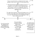
- FIG. 3 shows a process of setting up a virtual link between a core aggregation node and a remote access node; and specific steps are as follows:
- the virtual link forwarding entry includes a virtual link forwarding entry of the core aggregation node and a virtual link forwarding entry of the remote access node.
- An interface of an attachment circuit (Attachment Circuit) in the virtual link forwarding entry of the core aggregation node is the virtualized remote logical interface
- an interface of an attachment circuit in the virtual link forwarding entry of the remote access node is the external interface.
- control device generates a service forwarding entry of the core aggregation node by performing centralized calculation according to the service configured on the virtualized remote logical interface and a service protocol of the service to be processed, and sends the service forwarding entry to the core aggregation node, where an outbound interface of the service forwarding entry is the virtualized remote logical interface.
- the service forwarding entry includes a unicast Internet Protocol IP routing and forwarding entry, a Layer 3 virtual private network L3VPN routing and forwarding entry, or a Layer 2 virtual private network L2VPN forwarding entry.
- a PW (Pseudo wire) forwarding entry is used as an example of the virtual link forwarding entry herein; in an actual situation, the present invention is further applicable to other types of virtual link forwarding entries.
- control device sends the virtual link forwarding entry to the core aggregation node through a control channel between the control device and the core aggregation node, and the control device sends the virtual link forwarding entry to the remote access node through a control channel between the remote access node and the core aggregation node.
- step 302 and step 303 a scenario of two Masters is used as an example.
- the core aggregation node is classified into a main Master and a backup Master, and control devices of the main Master and the backup Master, separately generate a virtual link forwarding entry through calculation and deliver the virtual link forwarding entry, so as to set up a point-to-point virtual link between the core aggregation node and the remote access node.
- the control device of the main Master generates the virtual link forwarding entries of the remote access node and the main Master through calculation, delivers the virtual link forwarding entry of the main Master to the main Master; in addition, the main Master delivers the virtual link forwarding entry of the remote access node AP to the remote access node AP through a control channel between the remote access node AP (Access Point, AP for short) and the backup Master, where the control channel refers to a channel that is inside a virtual cluster and responsible for processing a packet such as a control and management protocol between the remote access node and the main Master or between the remote access node and the backup Master.
- AP Access Point
- a manner in which the backup Master calculates and sends the virtual link forwarding entry is the same as the foregoing manner, where the control device of the backup Master generates the virtual link forwarding entries of the backup Master and the remote AP through calculation, delivers the virtual link forwarding entry to the backup Master, and delivers the virtual link forwarding entry of the remote AP to the remote AP through the control channel between the backup Master and the remote AP.
- the method further includes:
- the control device when processing the L2VPN forwarding entry, binds the virtualized remote logical interface to an attachment circuit (Attachment Circuit, AC for short) interface table of the L2VPN forwarding entry; in this embodiment of the present invention, the attachment circuit AC interface table of the L2VPN forwarding entry is used as an example; however, in an actual process, it is not limited to the manner of binding to the attachment circuit AC interface table.
- attachment circuit Adtachment Circuit, AC for short
- An outbound interface in the L2VPN forwarding entry is the virtualized remote logical interface that is created on the core aggregation node for the external interface of the remote access node.
- a virtual link is set up between a core aggregation node and a remote access node through calculation inside the core aggregation node, and a routing and forwarding entry of a corresponding service protocol is forwarded through the virtual link, resolving a problem that complementary adaption inside a network virtualization routing system is required for each type of service when the network virtualization routing system processes unicast IP, L2VPN, and L3VPN services, which is complex to process and has poor connectivity, so that the network virtualization routing system that is based on separation of control and forwarding can support various types of services efficiently and with high quality.
- an embodiment of the present invention provides a method for data transmission of network virtualization, that is, provides a method that, in a scenario of a single Master, a control device identifies, according to a service configured on a virtualized remote logical interface, a service type of the service, and generates virtual link forwarding entries of a remote access node and a core aggregation node, so as to set up a virtual link between the core aggregation node and the remote access node, which mainly includes: identifying, according to the service configured on the virtualized remote logical interface, the service type of the service, and generating the virtual link forwarding entries of the remote access node and the core aggregation node.
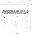
- FIG. 4 shows a process of setting up a virtual link between a core aggregation node and a remote access node; and specific steps are as follows:
- the virtual link forwarding entry includes a virtual link forwarding entry of the core aggregation node and a virtual link forwarding entry of the remote access node.
- An interface of an attachment circuit (Attachment Circuit) in the virtual link forwarding entry of the core aggregation node is the virtualized remote logical interface
- an interface of an attachment circuit in the virtual link forwarding entry of the remote access node is the external interface.
- control device generates a service forwarding entry of the core aggregation node by performing centralized calculation according to the service configured on the virtualized remote logical interface and a service protocol of the service to be processed, and sends the service forwarding entry to the core aggregation node, where an outbound interface of the service forwarding entry is the virtualized remote logical interface.
- the service forwarding entry includes a unicast Internet Protocol IP routing and forwarding entry, a Layer 3 virtual private network L3VPN routing and forwarding entry, or a Layer 2 virtual private network L2VPN forwarding entry.
- a PW (Pseudo wire) forwarding entry is used as an example of the virtual link forwarding entry herein; in an actual situation, the present invention is further applicable to other types of virtual link forwarding entries.
- the core aggregation node includes a core aggregation node as a main frame and a core aggregation node as a backup frame; and the core aggregation node as a main frame and the core aggregation node as a backup frame share the control device, where that the control device sends the virtual link forwarding entry to the remote access node and the core aggregation node specifically includes: sending, by the control device, the virtual link forwarding entry to the remote access node, the core aggregation node as a main frame, and the core aggregation node as a backup frame.
- control device sends the service forwarding entry to the core aggregation node includes: setting a routing entry in a first service forwarding entry that is generated for the core aggregation node as a main frame as a primary route, and sending the first service forwarding entry to the core aggregation node as a main frame; and setting a routing entry in a second service forwarding entry that is generated for the core aggregation node as a backup frame as a secondary route, and sending the second service forwarding entry to the core aggregation node as a backup frame.
- the method further includes:
- An outbound interface in the L2VPN forwarding entry is the virtualized remote logical interface that is created on the core aggregation node for the external interface of the remote access node.
- the control device herein separately generates an external L2VPN forwarding entry of a network virtualization system for a main frame and a backup frame of the core aggregation node, and separately delivers the L2VPN forwarding entries to the main frame and the backup frame; the main frame and the backup frame separately completes join processing on a virtual link outside the network virtualization system and a virtual link inside the network virtualization system.
- the join processing on a virtual link outside the network virtualization system and a virtual link inside the network virtualization system is joining a connection of L2VPN service data between a downlink virtual link inside the network virtualization system and the virtual link outside the network virtualization system, and a connection of the L2VPN service data between an uplink virtual link inside the network virtualization system and the virtual link outside the network virtualization system.
- a data transmission process of the L2VPN service data between the downlink virtual link inside the network virtualization system and the virtual link outside the network virtualization system is as follows:
- the control device processes an L2VPN service
- the control device generates L2VPN forwarding entries separately corresponding to the main frame and the backup frame, sends the L2VPN forwarding entry corresponding to the main frame to the main frame through a control channel between the control device and the main frame, and sends the L2VPN forwarding entry corresponding to the backup frame to the backup frame through a control channel between the control device and the backup frame
- the core aggregation node acquires that the outbound interface is the virtualized remote logical interface by querying an L2VPN routing and forwarding entry, maps to and associates with the virtual link inside the network virtualization system by means of the virtualized remote logical interface, and sends the service data to the remote access node through the virtual link
- the remote access node sends, by querying a virtual link forwarding table, the service data to the outside of
- a data transmission process of the L2VPN service data between the uplink virtual link inside the network virtualization system and the virtual link outside the network virtualization system is as follows:
- the core aggregation node selects an optimal path to transfer the data, so as to avoid or reduce inter-frame traffic waste between the main frame and the backup frame;
- the remote access node receives the service data through an external interface (that is, an AC interface), and sends, by querying the virtual link forwarding entry, the service data to the main frame or the backup frame of a corresponding core aggregation node through the virtual link between the remote access node and the core aggregation node;
- the core aggregation node receives, through the virtual link between the core aggregation node and the remote access node, the service data that is sent by the remote access node, acquires that the service data is L2VPN service data by querying the L2VPN routing entry, and sends the L2VPN service data to the outside of the network virtualization system through
- the control device when processing the L2VPN forwarding entry, binds the virtualized remote logical interface to an attachment circuit AC (Attachment circuit) interface table of the L2VPN forwarding entry.
- attachment circuit AC interface table of the L2VPN forwarding entry is used as an example herein; however, in an actual process, it is not limited to the manner of binding to the attachment circuit AC interface table.
- the L2VPN (Layer 2 virtual private network, Layer 2 Virtual Private Network) herein is to transparently transmit Layer 2 data of a user on a PSN (IP/MPLS) network. Seen from a perspective of a user, the PSN network herein is a Layer 2 switched network, and a Layer 2 connection may be set up between different sites by using this network.
- a virtual link is set up between a core aggregation node and a remote access node, a core aggregation node as a main frame and a core aggregation node as a backup frame are exchanged in terms of function during an actual operation, and a routing and forwarding entry of a corresponding service protocol is forwarded to the core aggregation node through the virtual link that is set up, resolving a problem that complementary adaption inside a network virtualization routing system is required for each type of service when the network virtualization routing system processes unicast IP, L2VPN, and L3VPN services, which is complex to process and has poor connectivity, so that the network virtualization routing system that is based on separation of control and forwarding can support various types of services efficiently and with high quality.
- an embodiment of the present invention provides a method for data transmission of network virtualization, that is, provides a method that, in a scenario of a plurality of Masters, a core aggregation node identifies, according to a service configured on a virtualized remote logical interface, a service type of the service, and generates virtual link forwarding entries of a remote access node and the core aggregation node, so as to set up a virtual link between the core aggregation node and the remote access node, which mainly includes: identifying, according to the service configured on the virtualized remote logical interface, the service type of the service, and generating the virtual link forwarding entries of the remote access node and the core aggregation node.
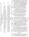
- FIG. 5 shows a process of setting up a virtual link between the core aggregation node and the remote access node; and specific steps are as follows:
- the virtual link forwarding entry herein includes a virtual link forwarding entry of the core aggregation node and a virtual link forwarding entry of the remote access node, where an interface of an attachment circuit (Aattachment Circuit) in the virtual link forwarding entry of the core aggregation node is the virtualized remote logical interface.
- Attachment Circuit attachment circuit
- the core aggregation node generates a service forwarding entry of the core aggregation node by performing centralized calculation according to the service configured on the virtualized remote logical interface and a service protocol of the service to be processed, and stores the service forwarding entry, where an outbound interface of the service forwarding entry is the virtualized remote logical interface.
- the service forwarding entry includes a unicast Internet Protocol IP routing and forwarding entry, a Layer 3 virtual private network L3VPN routing and forwarding entry, or a Layer 2 virtual private network L2VPN forwarding entry.
- a PW (Pseudo wire) forwarding entry is used as an example of the virtual link forwarding entry herein; in an actual situation, the present invention is further applicable to other types of virtual link forwarding entries.
- the core aggregation node sends the virtual link forwarding entry to the remote access node through a control channel between the remote access node and the core aggregation node.
- step 502 and step 503 a scenario of two Masters is used as an example.
- the core aggregation node is classified into a main Master and a backup Master, and control devices of the main Master and the backup Master separately generate a virtual link forwarding entry through calculation and deliver the virtual link forwarding entry, so as to set up a point-to-point virtual link between the core aggregation node and the remote access node.
- the control device when processing the L2VPN forwarding entry, the control device binds the virtualized remote logical interface to an attachment circuit (Attachment Circuit, AC for short) interface table of the L2VPN forwarding entry.
- attachment circuit Adtachment Circuit, AC for short
- the attachment circuit AC interface table of the L2VPN forwarding entry is used as an example herein; however, in an actual process, it is not limited to the manner of binding to the attachment circuit AC interface table.
- An outbound interface in the L2VPN forwarding entry is the virtualized remote logical interface that is created on the core aggregation node for the external interface of the remote access node.
- a virtual link is set up between a core aggregation node and a remote access node through calculation inside the core aggregation node, and a routing and forwarding entry of a corresponding service protocol is forwarded through the virtual link, resolving a problem that complementary adaption inside a network virtualization routing system is required for each type of service when the network virtualization routing system processes unicast IP, L2VPN, and L3VPN services, which is complex to process and has poor connectivity, so that the network virtualization routing system that is based on separation of control and forwarding can support various types of services efficiently and with high quality.
- an embodiment of the present invention provides a method for data transmission of network virtualization, that is, provides a method that, in a scenario of a single Master, a core aggregation node identifies, according to a service configured on a virtualized remote logical interface, a service type of the service, and generates virtual link forwarding entries of a remote access node and the core aggregation node, so as to set up a virtual link between the core aggregation node and the remote access node, which mainly includes: identifying, according to the service configured on the virtualized remote logical interface, the service type of the service, and generating the virtual link forwarding entries of the remote access node and the core aggregation node.
- FIG. 6 shows a process of setting up a virtual link between a core aggregation node and a remote access node; and specific steps are as follows:
- the virtual link forwarding entry herein includes a virtual link forwarding entry of the core aggregation node and a virtual link forwarding entry of the remote access node, where an interface of an attachment circuit (Aattachment Circuit) in the virtual link forwarding entry of the core aggregation node is the virtualized remote logical interface.
- Attachment Circuit attachment circuit
- the core aggregation node generates a service forwarding entry of the core aggregation node by performing centralized calculation according to the service configured on the virtualized remote logical interface and a service protocol of the service to be processed, and stores the service forwarding entry, where an outbound interface of the service forwarding entry is the virtualized remote logical interface.
- the service forwarding entry includes a unicast Internet Protocol IP routing and forwarding entry, a Layer 3 virtual private network L3VPN routing and forwarding entry, or a Layer 2 virtual private network L2VPN forwarding entry.
- a PW (Pseudo wire) forwarding entry is used as an example of the virtual link forwarding entry herein; in an actual situation, the present invention is further applicable to other types of virtual link forwarding entries.
- the core aggregation node includes a core aggregation node as a main frame and a core aggregation node as a backup frame, where that the core aggregation node sends the virtual link forwarding entry to the remote access node specifically includes: sending, by the core aggregation node as a main frame, the virtual link forwarding entry to the remote access node and the core aggregation node as a backup frame.
- the core aggregation node as a main frame sets a routing entry in a first service forwarding entry that is generated for the core aggregation node as a main frame as a primary route, and stores the first service forwarding entry; and the core aggregation node as a main frame sets a routing entry in a second service forwarding entry that is generated for the core aggregation node as a backup frame as a secondary route, and sends the second service forwarding entry to the core aggregation node as a backup frame.
- the method further includes:
- An outbound interface in the L2VPN forwarding entry is the virtualized remote logical interface that is created on the core aggregation node for the external interface of the remote access node.
- a virtual link is set up between a core aggregation node and a remote access node, a core aggregation node as a main frame and a core aggregation node as a backup frame are exchanged in terms of function during an actual operation, and a routing and forwarding entry of a corresponding service protocol is forwarded to the core aggregation node through the virtual link that is set up, resolving a problem that complementary adaption inside a network virtualization routing system is required for each type of service when the network virtualization routing system processes unicast IP, L2VPN, and L3VPN services, which is complex to process and has poor connectivity, so that the network virtualization routing system that is based on separation of control and forwarding can support various types of services efficiently and with high quality.
- An embodiment of the present invention provides a control device 7.
- the control device 7 includes: a logical interface setter 71, a data calculator 72, and a data transmitter 73.
- the logical interface setter 71 is configured to create, on the control device, a virtualized remote logical interface for an external interface of a remote access node, where the external interface of the remote access node is an interface that is configured to connect to another network device.
- the data calculator 72 is configured to identify, according to a service configured on the virtualized remote logical interface that is created by the logical interface setter, a service type of the service, and generate virtual link forwarding entries of the remote access node and a core aggregation node, where the virtual link forwarding entry includes a virtual link forwarding entry of the core aggregation node and a virtual link forwarding entry of the remote access node, an interface of an attachment circuit (Attachment Circuit) in the virtual link forwarding entry of the core aggregation node is the virtualized remote logical interface, and an interface of an attachment circuit in the virtual link forwarding entry of the remote access node is the external interface.
- a service configured on the virtualized remote logical interface that is created by the logical interface setter, a service type of the service
- virtual link forwarding entry includes a virtual link forwarding entry of the core aggregation node and a virtual link forwarding entry of the remote access node
- the data transmitter 73 is configured to send the virtual link forwarding entry that is generated by the data calculator to the remote access node and the core aggregation node, so as to set up a virtual link between the core aggregation node and the remote access node.
- a virtual link between a core aggregation node and a remote access node is set up, resolving a problem that complementary adaption inside a network virtualization routing system is required for each type of service when the network virtualization routing system processes unicast IP, L2VPN, and L3VPN services, which is complex to process and has poor connectivity, so that the network virtualization routing system that is based on separation of control and forwarding can support various types of services efficiently and with high quality.
- the data calculator 72 is further configured to generate a service forwarding entry of the core aggregation node by performing centralized calculation according to the service configured on the virtualized remote logical interface and a service protocol of the service to be processed, and send the service forwarding entry to the core aggregation node, where an outbound interface of the service forwarding entry is the virtualized remote logical interface.
- the service forwarding entry includes a unicast Internet Protocol IP routing and forwarding entry, a Layer 3 virtual private network L3VPN routing and forwarding entry, or a Layer 2 virtual private network L2VPN forwarding entry.
- the data transmitter 73 includes a data sending subunit 731.
- the data sending subunit 731 is configured to send the virtual link forwarding entry to the core aggregation node through a control channel between the control device and the core aggregation node, and send, the virtual link forwarding entry to the remote access node through a control channel between the remote access node and the core aggregation node.
- the core aggregation node includes a core aggregation node as a main frame and a core aggregation node as a backup frame; and the core aggregation node as a main frame and the core aggregation node as a backup frame share the control device.
- the data transmitter 73 is specifically further configured to send the virtual link forwarding entry to the remote access node, the core aggregation node as a main frame, and the core aggregation node as a backup frame.
- the data transmitter 73 is further configured to set a routing entry in a first service forwarding entry that is generated for the core aggregation node as a main frame as a primary route, and send the first service forwarding entry to the core aggregation node as a main frame.
- the data transmitter 73 is further configured to set a routing entry in a second service forwarding entry that is generated for the core aggregation node as a backup frame as a secondary route, and send the second service forwarding entry to the core aggregation node as a backup frame.
- a virtual link is set up between a core aggregation node and a remote access node, a core aggregation node as a main frame and a core aggregation node as a backup frame are exchanged in terms of function during an actual operation, and a routing and forwarding entry of a corresponding service protocol is forwarded to the core aggregation node through the virtual link that is set up, resolving a problem that complementary adaption inside a network virtualization routing system is required for each type of service when the network virtualization routing system processes unicast IP, L2VPN, and L3VPN services, which is complex to process and has poor connectivity, so that the network virtualization routing system that is based on separation of control and forwarding can support various types of services efficiently and with high quality.
- An embodiment of the present invention provides a core aggregation node 8.
- the core aggregation node may be specifically a device that can implement data transmission of network virtualization by using such as a large-capacity and high-performance router or switch in a mobile communications network.
- a specific form of the core aggregation node is not specifically limited in this embodiment of the present invention, it is acceptable as long as it can implement any one of the foregoing methods for data transmission of network virtualization provided by the embodiments of the present invention.
- the core aggregation node includes:
- a virtual link between the core aggregation node and a remote access node is set up, resolving a problem that complementary adaption inside a network virtualization routing system is required for each type of service when the network virtualization routing system processes unicast IP, L2VPN, and L3VPN services, which is complex to process and has poor connectivity, so that the network virtualization routing system that is based on separation of control and forwarding can support various types of services efficiently and with high quality.
- the data calculator 82 is further configured to generate a service forwarding entry of the core aggregation node by performing centralized calculation according to the service configured on the virtualized remote logical interface and a service protocol of the service to be processed, and store the service forwarding entry, where an outbound interface of the service forwarding entry is the virtualized remote logical interface.
- the service forwarding entry includes: a unicast Internet Protocol IP routing and forwarding entry, a Layer 3 virtual private network L3VPN routing and forwarding entry, or a Layer 2 virtual private network L2VPN forwarding entry.
- the data transmitter 83 includes:
- the core aggregation node includes a core aggregation node as a main frame and a core aggregation node as a backup frame.
- the data transmitter 83 is specifically further configured to send the virtual link forwarding entry to the remote access node and the core aggregation node as a backup frame.
- the data transmitter 83 is further configured to set a routing entry in a first service forwarding entry that is generated for the core aggregation node as a main frame as a primary route, and store the first service forwarding entry; and set, by using the core aggregation node as a main frame, a routing entry in a second service forwarding entry that is generated for the core aggregation node as a backup frame as a secondary route, and send the second service forwarding entry to the core aggregation node as a backup frame.
- a virtual link is set up between a core aggregation node and a remote access node, a core aggregation node as a main frame and a core aggregation node as a backup frame are exchanged in terms of function during an actual operation, and a routing and forwarding entry of a corresponding service protocol is forwarded to the core aggregation node through the virtual link that is set up, resolving a problem that complementary adaption inside a network virtualization routing system is required for each type of service when the network virtualization routing system processes unicast IP, L2VPN, and L3VPN services, which is complex to process and has poor connectivity, so that the network virtualization routing system that is based on separation of control and forwarding can support various types of services efficiently and with high quality.
- the present invention provides a control device 9.
- the device may be embedded into a micro-processing computer or be a micro-processing computer itself, for example, a general-purpose computer, a customized computer, or a portable device such as a mobile phone terminal or a tablet computer, and include: at least one processor 91, a memory 92, a communications interface 93, and a bus 94.
- the processor 91, the memory 92, and the communications interface 93 are connected and communicate with each other by using the bus 94.
- the bus 94 may be an industry standard architecture (Industry Standard Architecture, ISA for short) bus, a peripheral component interconnect (Peripheral Component Interconnect, PCI for short) bus, an extended industry standard architecture (Extended Industry Standard Architecture, EISA for short) bus, or the like.
- the bus may be classified into an address bus, a data bus, a control bus, and the like.
- the bus is represented by using only one thick line in FIG. 11 ; however, it does not indicate that there is only one bus or only one type of bus.
- the memory 92 is configured to store executable program code, where the program code includes computer operation instructions.
- the memory 92 may include a high-speed RAM memory, and may also further include a non-volatile memory (non-volatile memory), such as at least one disk memory.
- the processor 91 may be a central processing unit (Central Processing Unit, CPU for short) or an application-specific integrated circuit (Application-Specific Integrated Circuit, ASIC for short), or be configured as one or more integrated circuits implementing the embodiments the present invention.
- CPU Central Processing Unit
- ASIC Application-Specific Integrated Circuit
- the communications interface 93 is mainly configured to implement communication between apparatuses in this embodiment.
- the processor 91 is configured to create, on the control device, a virtualized remote logical interface for an external interface of a remote access node, where the external interface of the remote access node is an interface that is configured to connect to another network device.
- the processor 91 is further configured to identify, according to a service configured on the virtualized remote logical interface, a service type of the service, and generate virtual link forwarding entries of the remote access node and a core aggregation node, where the virtual link forwarding entry includes a virtual link forwarding entry of the core aggregation node and a virtual link forwarding entry of the remote access node, an interface of an attachment circuit (Attachment Circuit) in the virtual link forwarding entry of the core aggregation node is the virtualized remote logical interface, and an interface of an attachment circuit in the virtual link forwarding entry of the remote access node is the external interface.
- an attachment circuit Alignment Circuit
- the processor 91 is further configured to send the virtual link forwarding entry to the remote access node and the core aggregation node through at least one communications interface, so as to set up a virtual link between the core aggregation node and the remote access node.
- a virtual link is set up between a core aggregation node and a remote access node, resolving a problem that complementary adaption inside a network virtualization routing system is required for each type of service when the network virtualization routing system processes unicast IP, L2VPN, and L3VPN services, which is complex to process and has poor connectivity, so that the network virtualization routing system that is based on separation of control and forwarding can support various types of services efficiently and with high quality.
- the processor 91 is further configured to generate a service forwarding entry of the core aggregation node by performing centralized calculation according to the service configured on the virtualized remote logical interface and a service protocol of the service to be processed, and send the service forwarding entry to the core aggregation node through the at least one communications interface, where an outbound interface of the service forwarding entry is the virtualized remote logical interface.
- the service forwarding entry includes a unicast Internet Protocol IP routing and forwarding entry, a Layer 3 virtual private network L3VPN routing and forwarding entry, or a Layer 2 virtual private network L2VPN forwarding entry.
- the processor 91 is further configured to send the virtual link forwarding entry to the core aggregation node through a control channel between the control device and the core aggregation node and through the at least one communications interface, and send, by using the control device, the virtual link forwarding entry to the remote access node through a control channel between the remote access node and the core aggregation node.
- the core aggregation node includes a core aggregation node as a main frame and a core aggregation node as a backup frame; and the core aggregation node as a main frame and the core aggregation node as a backup frame share the control device.
- the processor 91 is specifically further configured to send the virtual link forwarding entry to the remote access node, the core aggregation node as a main frame, and the core aggregation node as a backup frame through the at least one communications interface.
- the processor 91 is further configured to set a routing entry in a first service forwarding entry that is generated for the core aggregation node as a main frame as a primary route, and send the first service forwarding entry to the core aggregation node as a main frame through the at least one communications interface.
- the processor 91 is further configured to set a routing entry in a second service forwarding entry that is generated for the core aggregation node as a backup frame as a secondary route, and send the second service forwarding entry to the core aggregation node as a backup frame through the at least one communications interface.
- a virtual link is set up between a core aggregation node and a remote access node, a core aggregation node as a main frame and a core aggregation node as a backup frame are exchanged in terms of function during an actual operation, and a routing and forwarding entry of a corresponding service protocol is forwarded to the core aggregation node through the virtual link that is set up, resolving a problem that complementary adaption inside a network virtualization routing system is required for each type of service when the network virtualization routing system processes unicast IP, L2VPN, and L3VPN services, which is complex to process and has poor connectivity, so that the network virtualization routing system that is based on separation of control and forwarding can support various types of services efficiently and with high quality.
- the present invention provides a core aggregation node 10.
- the core aggregation node may be embedded into a micro-processing computer or be a micro-processing computer itself, for example, a general-purpose computer, a customized computer, or a portable device such as a mobile phone terminal or a tablet computer, and include: at least one processor 1001, a memory 1002, a communications interface 1003, and a bus 1004.
- the processor 1001, the memory 1002, and the communications interface 1003 are connected and communicate with each other by using the bus 1004.
- the bus 1004 may be an industry standard architecture (Industry Standard Architecture, ISA for short) bus, a peripheral component interconnect (Peripheral Component, PCI for short) bus, an extended industry standard architecture (Extended Industry Standard Architecture, EISA for short) bus, or the like.
- the bus may be classified into an address bus, a data bus, a control bus, and the like.
- the bus is represented by using only one thick line in FIG. 12 ; however, it does not indicate that there is only one bus or only one type of bus.
- the memory 1002 is configured to store executable program code, where the program code includes computer operation instructions.
- the memory 1002 may include a high-speed RAM memory, and may also further include a non-volatile memory (non-volatile memory), such as at least one disk memory.
- the processor 1001 may be a central processing unit (Central Processing Unit, CPU for short) or an application-specific integrated circuit (Application Specific Integrated Circuit, ASIC for short), or be configured as one or more integrated circuits implementing the embodiments the present invention.
- CPU Central Processing Unit
- ASIC Application Specific Integrated Circuit
- the communications interface 1003 is mainly configured to implement communication between apparatuses in this embodiment.
- the processor 1001 is configured to create, on the core aggregation node, a virtualized remote logical interface for an external interface of a remote access node, where the external interface of the remote access node is an interface that is configured to connect to another network device.
- the processor 1001 is further configured to identify, according to a service configured on the virtualized remote logical interface, a service type of the service, and generate virtual link forwarding entries of the remote access node and the core aggregation node, where the virtual link forwarding entry includes a virtual link forwarding entry of the core aggregation node and a virtual link forwarding entry of the remote access node, and an interface of an attachment circuit (Aattachment Circuit) in the virtual link forwarding entry of the core aggregation node is the virtualized remote logical interface.
- Aattachment Circuit attachment circuit
- the processor 1001 is further configured to store the virtual link forwarding entry of the core aggregation node, and send the virtual link forwarding entry of the remote access node to the remote access node, so as to set up a virtual link between the core aggregation node and the remote access node.
- a virtual link between the core aggregation node and a remote access node is set up, resolving a problem that complementary adaption inside a network virtualization routing system is required for each type of service when the network virtualization routing system processes unicast IP, L2VPN, and L3VPN services, which is complex to process and has poor connectivity, so that the network virtualization routing system that is based on separation of control and forwarding can support various types of services efficiently and with high quality.
- the processor 1001 is further configured to generate a service forwarding entry of the core aggregation node by performing centralized calculation according to the service configured on the virtualized remote logical interface and a service protocol of the service to be processed, and store the service forwarding entry, where an outbound interface of the service forwarding entry is the virtualized remote logical interface.
- the service forwarding entry includes a unicast Internet Protocol IP routing and forwarding entry, a Layer 3 virtual private network L3VPN routing and forwarding entry, or a Layer 2 virtual private network L2VPN forwarding entry.
- the processor 1001 is further configured to send the virtual link forwarding entry to the remote access node through a control channel between the remote access node and the core aggregation node and through at least one communications interface.
- the core aggregation node includes a core aggregation node as a main frame and a core aggregation node as a backup frame.
- the processor 1001 is specifically further configured to send the virtual link forwarding entry to the remote access node and the core aggregation node as a backup frame through the at least one communications interface.
- the processor 1001 is further configured to set a routing entry in a first service forwarding entry that is generated for the core aggregation node as a main frame as a primary route, and store the first service forwarding entry; and set, by using the core aggregation node as a main frame, a routing entry in a second service forwarding entry that is generated for the core aggregation node as a backup frame as a secondary route, and send the second service forwarding entry to the core aggregation node as a backup frame.
- a virtual link is set up between a core aggregation node and a remote access node, a core aggregation node as a main frame and a core aggregation node as a backup frame are exchanged in terms of function during an actual operation, and a routing and forwarding entry of a corresponding service protocol is forwarded to the core aggregation node through the virtual link that is set up, resolving a problem that complementary adaption inside a network virtualization routing system is required for each type of service when the network virtualization routing system processes unicast IP, L2VPN, and L3VPN services, which is complex to process and has poor connectivity, so that the network virtualization routing system that is based on separation of control and forwarding can support various types of services efficiently and with high quality.
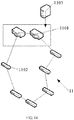
- the present invention provides a routing system 11.
- the routing system 11 includes at least two core aggregation nodes 1101, a plurality of remote access nodes 1102 separately connected to the core aggregation nodes, and at least one control device 1103 connected to any one of the core aggregation nodes, where the control device 1103 is any control device shown in FIG. 7 or FIG. 8 , or the control device 1103 is the control device shown in FIG. 11 .
- a scenario of two Masters is used as an example, as shown in FIG. 13 .
- the routing system 11 includes one control device 1103, and the control device is connected to any one core aggregation node 1101.
- the core aggregation node 1101 is classified into a main frame and a backup frame, where the main frame may be a first core aggregation node, and the backup frame may be a second core aggregation node.
- the first core aggregation node may also be used as the backup frame and the second core aggregation node may be used as the main frame, where the main frame and the backup frame are in communication with each other, and the main frame and the backup frame are virtualized into one core aggregation node on a control plane and share one control device.
- the core aggregation node is set as the main frame
- the other core aggregation node is set as the backup frame
- the main frame is mainly responsible for a function of processing a service packet
- the backup frame forwards a service data packet in replace of the main frame when the main frame cannot run normally.
- the first core aggregation node and the second core aggregation node may be exchanged under a special situation, and the function helps improve efficiency of processing various services.
- the core aggregation node 1101 is further configured to: if an outbound interface that is of the routing system and corresponding to a routing and forwarding entry of the core aggregation node is on the core aggregation node, directly encapsulate, by using the core aggregation node, a service data packet on the outbound interface, and forward the packet to a device connected to the outside of the routing system, wherein, the service data packet of a service protocol corresponding to the core aggregation node refers to a service data packet that is generated after service data in case of protocols, such as a unicast IP service protocol, an L2VPN service protocol, or an L3VPN service protocol, is processed on a virtualized remote logical interface of the core aggregation node; and if the outbound interface that is of the routing system and corresponding to the routing and forwarding entry of the core aggregation node is on a remote access node, send the service data packet out through an outbound interface connected to a tunnel
- an internal outbound interface of the core aggregation node 1101 refers to a port that connects the core aggregation node and an external network environment and that is configured to forward a data packet.
- the remote access node 1102 is further configured to: if an outbound interface that is of the routing system and in a service forwarding entry of the remote access node is on the remote access node:
- a virtual link is set up between a core aggregation node and a remote access node, resolving a problem that complementary adaption inside a network virtualization routing system is required for each type of service when the network virtualization routing system processes unicast IP, L2VPN, and L3VPN services, which is complex to process and has poor connectivity, so that the network virtualization routing system that is based on separation of control and forwarding can support various types of services efficiently and with high quality.
- the present invention provides a routing system 12.
- the routing system 12 includes at least one core aggregation node 1201 and a remote access node 1202 connected to the at least one core aggregation node, where the core aggregation node 1201 is any core aggregation node shown in FIG. 9 or FIG. 10 , or the core aggregation node 1201 is any core aggregation node shown in FIG. 12 .
- a scenario of two Masters is used as an example, as shown in FIG. 15 .
- the core aggregation node 1201 is classified into a main frame and a backup frame, where the main frame may be a first core aggregation node and the backup frame may be a second core aggregation node; certainly, the first core aggregation node may also be used as the backup frame and the second core aggregation node may be used as the main frame, and the main frame and the backup frame are in communication with each other.
- the core aggregation node is set as the main frame
- the other core aggregation node is set as the backup frame
- the main frame is mainly responsible for a function of processing a service packet
- the backup frame forwards a service data packet in replace of the main frame when the main frame cannot run normally.
- the first core aggregation node and the second core aggregation node may be exchanged under a special situation, and the function helps improve efficiency of processing various services.
- the core aggregation node can create a service configured on a virtualized remote logical interface, identify a service type of the service, and generate virtual link forwarding entries of the remote access node and the core aggregation node, which is equivalent to that a control device is placed in the core aggregation node, so that the core aggregation node can generate a virtual link forwarding entry through calculation according to service types of different services.
- a virtual link is set up between a core aggregation node and a remote access node, resolving a problem that complementary adaption inside a network virtualization routing system is required for each type of service when the network virtualization routing system processes unicast IP, L2VPN, and L3VPN services, which is complex to process and has poor connectivity, so that the network virtualization routing system that is based on separation of control and forwarding can support various types of services efficiently and with high quality.
Description
- The present invention relates to the field of communications, and in particular, to a method, a device, and a routing system for data transmission of network virtualization.
- Base station backhaul (RadioAccessNet-work, RAN for short) refers to a transport network centralized between a base transceiver station (Base Transceiver Station, BTS for short) and a base station controller (Base Station Controller, BSC for short). An Internet Protocol radio access network IPRAN (Internet Protocol Radio Access Network, IPRAN for short) is a router/switch total solution that is optimized and customized for an application scenario of the base station backhaul, and has capabilities such as circuit simulation and synchronization, which improves operation administration and maintenance (Operation Administration and Maintenance, OAM for short) and protection capabilities. An IPRAN supporting solution is a solution in which an aggregation/core layer in a metropolitan area network uses an Internet Protocol/multi-protocol label switching (Internet Protocol/Multi-Protocol Label Switching, IP/MPLS for short) technology, and an access layer mainly uses an enhanced Ethernet technology or the IP/MPLS technology, where a device used on a core aggregation node is a router that supports IP/MPLS, and a device used on a base station access node is a router or a
Layer 3 switch. - At present, a solution to an IPRAN is complex to configure and manage, and a network virtualization technology may be introduced to the IPRAN to simplify a network structure, reduce costs, and simplify configuration, management, and maintenance. However, in an existing network virtualization processing solution for a metropolitan area network and IPRAN, connectivity of various services inside a network virtualization routing system is implemented by setting up, according to different service types such as unicast IP, L2VPN, and L3VPN services, corresponding IP, L2VPN, and L3VPN service channels inside the network virtualization routing system. This requires complementary adaption inside the network virtualization routing system for each type of service, which is complex to process and has poor connectivity.
US 2005/0102420 A1 discloses a shared network system, sharing method and router device for routing data packets in an IP transport network. Separate dedicated link layers having predetermined dedicated link capacities are allocated for transmitting and/or receiving data packets, wherein the dedicated link layers share an available capacity of a real link layer or physical layer.
US 2009/0219934 A1 discloses a network device seamlessly handling multicast traffic flow between virtual private networks (VPNs) and content providers located external to the VPNs. For example, the network device, such as a router, comprises an interface card and a forwarding component. The forwarding component maintains forwarding data for a public network and forwarding data for the virtual private network. The interface card receives a multicast packet from a virtual private network destined for a multicast content provider external to the virtual private network. When forwarding the multicast packet, the forwarding component bypasses the forwarding data for the public network and forwards the multicast packet to the multicast content provider in accordance with the forwarding data for the public network.
US 2004/0013120 A1 discloses a method and apparatus for routing and forwarding between virtual routers. A method in a single network element comprises peering a first virtual router to a second virtual router, wherein the first and second virtual routers have separate address spaces and separate routing tables, distributing a set of one or more routes from the first virtual router to the second virtual router, wherein a first of the set of routes identifies the first virtual router as a next hop of the first route, said first route including a destination, and downloading to a set of one or more forwarding tables, the destination and the next hop. - Embodiments of the present invention provide a method, a device, and a routing system for data transmission of network virtualization, and resolves a problem that complementary adaption inside a network virtualization routing system is required for each type of service when the network virtualization routing system processes unicast IP, L2VPN, and L3VPN services, which is complex to process and has poor connectivity, so that the network virtualization routing system that is based on separation of control and forwarding can support various types of services efficiently and with high quality.
- To achieve the foregoing objectives, the embodiments of the present invention use the following technical solutions:
- According to a first aspect, a method for data transmission in a network virtualization routing system is provided, including:
- creating, on a control device, a virtualized remote logical interface for an external interface of a remote access node, where the external interface of the remote access node is an interface that is configured to connect to another network device;
- identifying, by the control device according to a service configured on the virtualized remote logical interface, a service type of the service, and generating virtual link forwarding entries of the remote access node and a core aggregation node, where the virtual link forwarding entries include a virtual link forwarding entry of the core aggregation node and a virtual link forwarding entry of the remote access node, an interface of an attachment circuit (Attachment Circuit) in the virtual link forwarding entry of the core aggregation node is the virtualized remote logical interface, and an interface of an attachment circuit in the virtual link forwarding entry of the remote access node is the external interface; and
- sending, by the control device, the virtual link forwarding entry to the remote access node and the core aggregation node, so as to set up a virtual link between the core aggregation node and the remote access node.
- With reference to the first aspect, in a first possible implementation manner, the method specifically includes: generating, by the control device, a service forwarding entry of the core aggregation node, by performing centralized calculation according to the service configured on the virtualized remote logical interface and a service protocol of the service to be processed, and sending the service forwarding entry to the core aggregation node, where an outbound interface of the service forwarding entry is the virtualized remote logical interface.
- With reference to the first possible implementation manner, in a second possible implementation manner, the service forwarding entry includes a unicast Internet Protocol IP routing and forwarding entry, a
Layer 3 virtual private network L3VPN routing and forwarding entry, or aLayer 2 virtual private network L2VPN forwarding entry. - With reference to the first aspect, the first possible implementation manner, or the second possible implementation manner, in a third possible implementation manner,
- the sending, by the control device, the virtual link forwarding entry to the remote access node and the core aggregation node includes:
- sending, by the control device, the virtual link forwarding entry to the core aggregation node through a control channel between the control device and the core aggregation node, and sending, by the control device, the virtual link forwarding entry to the remote access node through a control channel between the remote access node and the core aggregation node.
- With reference to the first aspect, the first possible implementation manner, the second possible implementation manner, or the third possible implementation manner, in a fourth possible implementation manner, the core aggregation node includes a core aggregation node as a main frame and a core aggregation node as a backup frame; and the core aggregation node as a main frame and the core aggregation node as a backup frame share the control device, where the sending, by the control device, the virtual link forwarding entry to the remote access node and the core aggregation node specifically includes: sending, by the control device, the virtual link forwarding entry to the remote access node, the core aggregation node as a main frame, and the core aggregation node as a backup frame.
- With reference to the fourth possible implementation manner, in a fifth possible implementation manner, the sending the service forwarding entry to the core aggregation node includes: setting a routing entry in a first service forwarding entry that is generated for the core aggregation node as a main frame as a primary route, and sending the first service forwarding entry to the core aggregation node as a main frame; and setting a routing entry in a second service forwarding entry that is generated for the core aggregation node as a backup frame as a secondary route, and sending the second service forwarding entry to the core aggregation node as a backup frame.
- According to a second aspect, a method for data transmission in a network virtualization routing system is provided, including:
- creating, on a core aggregation node, a virtualized remote logical interface for an external interface of a remote access node, where the external interface of the remote access node is an interface that is configured to connect to another network device;
- identifying, by the core aggregation node according to a service configured on the virtualized remote logical interface, a service type of the service, and generating virtual link forwarding entries of the remote access node and the core aggregation node, where the virtual link forwarding entries include a virtual link forwarding entry of the core aggregation node and a virtual link forwarding entry of the remote access node, and an interface of an attachment circuit (Aattachment Circuit) in the virtual link forwarding entry of the core aggregation node is the virtualized remote logical interface; and
- storing, by the core aggregation node, the virtual link forwarding entry of the core aggregation node, and sending the virtual link forwarding entry of the remote access node to the remote access node, so as to set up a virtual link between the core aggregation node and the remote access node.
- With reference to the second aspect, in a first possible implementation manner, the method specifically includes: generating, by the core aggregation node, a service forwarding entry of the core aggregation node, by performing centralized calculation according to the service configured on the virtualized remote logical interface and a service protocol of the service to be processed, and storing the service forwarding entry, where an outbound interface of the service forwarding entry is the virtualized remote logical interface.
- With reference to the first possible implementation manner, in a second possible implementation manner, the service forwarding entry includes a unicast Internet Protocol IP routing and forwarding entry, a
Layer 3 virtual private network L3VPN routing and forwarding entry, or aLayer 2 virtual private network L2VPN forwarding entry. - With reference to the second aspect, the first possible implementation manner, or the second possible implementation manner, in a third possible implementation manner, the sending, by the core aggregation node, the virtual link forwarding entry to the remote access node includes:
- sending, by the core aggregation node, the virtual link forwarding entry to the remote access node through a control channel between the remote access node and the core aggregation node.
- With reference to the second aspect, the first possible implementation manner, the second possible implementation manner, or the third possible implementation manner, in a fourth possible implementation manner, the core aggregation node includes a core aggregation node as a main frame and a core aggregation node as a backup frame, where the sending, by the core aggregation node, the virtual link forwarding entry to the remote access node specifically includes: sending, by the core aggregation node as a main frame, the virtual link forwarding entry to the remote access node and the core aggregation node as a backup frame.
- With reference to the fourth possible implementation manner, in a fifth possible implementation manner, the method specifically includes: setting, by the core aggregation node as a main frame, a routing entry in a first service forwarding entry that is generated for the core aggregation node as a main frame as a primary route, and storing the first service forwarding entry; and setting, by the core aggregation node as a main frame, a routing entry in a second service forwarding entry that is generated for the core aggregation node as a backup frame as a secondary route, and sending the second service forwarding entry to the core aggregation node as a backup frame.
- According to a third aspect, a control device is provided, including:
- a logical interface setter, configured to create, on the control device, a virtualized remote logical interface for an external interface of a remote access node, where the external interface of the remote access node is an interface that is configured to connect to another network device;
- a data calculator, configured to identify, according to a service configured on the virtualized remote logical interface that is created by the logical interface setter, a service type of the service, and generate virtual link forwarding entries of the remote access node and a core aggregation node, where the virtual link forwarding entry includes a virtual link forwarding entry of the core aggregation node and a virtual link forwarding entry of the remote access node, an interface of an attachment circuit (Attachment Circuit) in the virtual link forwarding entry of the core aggregation node is the virtualized remote logical interface, and an interface of an attachment circuit in the virtual link forwarding entry of the remote access node is the external interface; and
- a data transmitter, configured to send the virtual link forwarding entry that is generated by the data calculator to the remote access node and the core aggregation node, so as to set up a virtual link between the core aggregation node and the remote access node.
- With reference to the third aspect, in a first possible implementation manner, the data calculator is further configured to generate a service forwarding entry of the core aggregation node by performing centralized calculation according to the service configured on the virtualized remote logical interface and a service protocol of the service to be processed, and send the service forwarding entry to the core aggregation node, where an outbound interface of the service forwarding entry is the virtualized remote logical interface.
- With reference to the first possible implementation manner, in a second possible implementation manner, the service forwarding entry includes a unicast Internet Protocol IP routing and forwarding entry, a
Layer 3 virtual private network L3VPN routing and forwarding entry, or aLayer 2 virtual private network L2VPN forwarding entry. - With reference to the third aspect, the first possible implementation manner, or the second possible implementation manner, in a third possible implementation manner, the data transmitter includes:
- a data sending subunit, configured to send the virtual link forwarding entry to the core aggregation node through a control channel between the control device and the core aggregation node, and send, by using the control device, the virtual link forwarding entry to the remote access node through a control channel between the remote access node and the core aggregation node.
- With reference to the third aspect, the first possible implementation manner, the second possible implementation manner, or the third possible implementation manner, in a fourth possible implementation manner,
- the core aggregation node includes a core aggregation node as a main frame and a core aggregation node as a backup frame; and the core aggregation node as a main frame and the core aggregation node as a backup frame share the control device, where
- the data transmitter is specifically further configured to send the virtual link forwarding entry to the remote access node, the core aggregation node as a main frame, and the core aggregation node as a backup frame.
- With reference to the fourth possible implementation manner, in a fifth possible implementation manner,
- the data transmitter is further configured to set a routing entry in a first service forwarding entry that is generated for the core aggregation node as a main frame as a primary route, and send the first service forwarding entry to the core aggregation node as a main frame; and
- the data transmitter is further configured to set a routing entry in a second service forwarding entry that is generated for the core aggregation node as a backup frame as a secondary route, and send the second service forwarding entry to the core aggregation node as a backup frame.
- According to a fourth aspect, a core aggregation node is provided, including:
- a logical interface setter, configured to create, on the core aggregation node, a virtualized remote logical interface for an external interface of a remote access node, where the external interface of the remote access node is an interface that is configured to connect to another network device;
- a data calculator, configured to identify, according to a service configured on the virtualized remote logical interface that is created by the logical interface setter, a service type of the service, and generate virtual link forwarding entries of the remote access node and the core aggregation node, where the virtual link forwarding entry includes a virtual link forwarding entry of the core aggregation node and a virtual link forwarding entry of the remote access node, and an interface of an attachment circuit (Aattachment Circuit) in the virtual link forwarding entry of the core aggregation node is the virtualized remote logical interface; and
- a data transmitter, configured to store the virtual link forwarding entry of the core aggregation node, and send the virtual link forwarding entry that is of the remote access node and generated by the data calculator to the remote access node, so as to set up a virtual link between the core aggregation node and the remote access node.
- With reference to the fourth aspect, in a first possible implementation manner, the data calculator is further configured to generate a service forwarding entry of the core aggregation node by performing centralized calculation according to the service configured on the virtualized remote logical interface and a service protocol of the service to be processed, and store the service forwarding entry, where an outbound interface of the service forwarding entry is the virtualized remote logical interface.
- With reference to the first possible implementation manner, in a second possible implementation manner, the service forwarding entry includes a unicast Internet Protocol IP routing and forwarding entry, a
Layer 3 virtual private network L3VPN routing and forwarding entry, or aLayer 2 virtual private network L2VPN forwarding entry. - With reference to the fourth aspect, the first possible implementation manner, or the second possible implementation manner, in a third possible implementation manner, the data transmitter includes:
- a data sending subunit, configured to send the virtual link forwarding entry to the remote access node through a control channel between the remote access node and the core aggregation node.
- With reference to the fourth aspect, the first possible implementation manner, or the second possible implementation manner, or the third possible implementation manner, in a fourth possible implementation manner, the core aggregation node includes a core aggregation node as a main frame and a core aggregation node as a backup frame, where
- the data transmitter is specifically further configured to send the virtual link forwarding entry to the remote access node and the core aggregation node as a backup frame.
- With reference to the fourth possible implementation manner, in a fifth possible implementation manner, the data transmitter is further configured to set a routing entry in a first service forwarding entry that is generated for the core aggregation node as a main frame as a primary route, and store the first service forwarding entry; and set, by using the core aggregation node as a main frame, a routing entry in a second service forwarding entry that is generated for the core aggregation node as a backup frame as a secondary route, and send the second service forwarding entry to the core aggregation node as a backup frame.
- According to a fifth aspect, a control device is provided, including: a processor and a memory that are connected by using a data bus, and a communications port that is separately connected to the processor and the memory, where:
- the processor is configured to create, on the control device, a virtualized remote logical interface for an external interface of a remote access node, where the external interface of the remote access node is an interface that is configured to connect to another network device;
- the processor is further configured to identify, according to a service configured on the virtualized remote logical interface, a service type of the service, and generate virtual link forwarding entries of the remote access node and a core aggregation node, where the virtual link forwarding entry includes a virtual link forwarding entry of the core aggregation node and a virtual link forwarding entry of the remote access node, an interface of an attachment circuit (Attachment Circuit) in the virtual link forwarding entry of the core aggregation node is the virtualized remote logical interface, and an interface of an attachment circuit in the virtual link forwarding entry of the remote access node is the external interface; and
- the processor is further configured to send the virtual link forwarding entry to the remote access node and the core aggregation node through the at least one communications interface, so as to set up a virtual link between the core aggregation node and the remote access node.
- With reference to the fifth aspect, in a first possible implementation manner, the processor is further configured to generate a service forwarding entry of the core aggregation node by performing centralized calculation according to the service configured on the virtualized remote logical interface and a service protocol of the service to be processed, and send the service forwarding entry to the core aggregation node through the at least one communications interface, where an outbound interface of the service forwarding entry is the virtualized remote logical interface.
- With reference to the first possible implementation manner, in a second possible implementation manner, the service forwarding entry includes a unicast Internet Protocol IP routing and forwarding entry, a
Layer 3 virtual private network L3VPN routing and forwarding entry, or aLayer 2 virtual private network L2VPN forwarding entry. - With reference to the fifth aspect, the first possible implementation manner, or the second possible implementation manner, in a third possible implementation manner, the processor is further configured to send the virtual link forwarding entry to the core aggregation node through a control channel between the control device and the core aggregation node and through the at least one communications interface, and send, by using the control device, the virtual link forwarding entry to the remote access node through a control channel between the remote access node and the core aggregation node.
- With reference to the fifth aspect, the first possible implementation manner, the second possible implementation manner, or the third possible implementation manner, in a fourth possible implementation manner, the core aggregation node includes a core aggregation node as a main frame and a core aggregation node as a backup frame; and the core aggregation node as a main frame and the core aggregation node as a backup frame share the control device, where
- the processor is specifically further configured to send the virtual link forwarding entry to the remote access node, the core aggregation node as a main frame, and the core aggregation node as a backup frame through the at least one communications interface.
- With reference to the fourth possible implementation manner, in a fifth possible implementation manner, the processor is further configured to set a routing entry in a first service forwarding entry that is generated for the core aggregation node as a main frame as a primary route, and send the first service forwarding entry to the core aggregation node as a main frame through the at least one communications interface; and
- the processor is further configured to set a routing entry in a second service forwarding entry that is generated for the core aggregation node as a backup frame as a secondary route, and send the second service forwarding entry to the core aggregation node as a backup frame through the at least one communications interface.
- According to a sixth aspect, a core aggregation node is provided, including: a processor and a memory that are connected by using a data bus, and a communications port that is separately connected to the processor and the memory, where:
- the processor is configured to create, on the core aggregation node, a virtualized remote logical interface for an external interface of a remote access node, where the external interface of the remote access node is an interface that is configured to connect to another network device;
- the processor is further configured to identify, according to a service configured on the virtualized remote logical interface, a service type of the service, and generate virtual link forwarding entries of the remote access node and the core aggregation node, where the virtual link forwarding entry includes a virtual link forwarding entry of the core aggregation node and a virtual link forwarding entry of the remote access node, and an interface of an attachment circuit (Aattachment Circuit) in the virtual link forwarding entry of the core aggregation node is the virtualized remote logical interface; and
- the processor is further configured to store the virtual link forwarding entry of the core aggregation node, and send the virtual link forwarding entry of the remote access node to the remote access node, so as to set up a virtual link between the core aggregation node and the remote access node.
- With reference to the sixth aspect, in a first possible implementation manner, the processor is further configured to generate a service forwarding entry of the core aggregation node by performing centralized calculation according to the service configured on the virtualized remote logical interface and a service protocol of the service to be processed, and store the service forwarding entry, where an outbound interface of the service forwarding entry is the virtualized remote logical interface.
- With reference to the first possible implementation manner, in a second possible implementation manner, the service forwarding entry includes a unicast Internet Protocol IP routing and forwarding entry, a
Layer 3 virtual private network L3VPN routing and forwarding entry, or aLayer 2 virtual private network L2VPN forwarding entry. - With reference to the sixth aspect, the first possible implementation manner, or the second possible implementation manner, in a third possible implementation manner, the processor is further configured to send the virtual link forwarding entry to the remote access node through a control channel between the remote access node and the core aggregation node and through the at least one communications interface.
- With reference to the sixth aspect, the first possible implementation manner, the second possible implementation manner, or the third possible implementation manner, in a fourth possible implementation manner, the core aggregation node includes a core aggregation node as a main frame and a core aggregation node as a backup frame, where
- the processor is specifically further configured to send the virtual link forwarding entry to the remote access node and the core aggregation node as a backup frame through the at least one communications interface.
- With reference to the fourth possible implementation manner, in a fifth possible implementation manner, the processor is further configured to set a routing entry in a first service forwarding entry that is generated for the core aggregation node as a main frame as a primary route, and store the first service forwarding entry; and set, by using the core aggregation node as a main frame, a routing entry in a second service forwarding entry that is generated for the core aggregation node as a backup frame as a secondary route, and send the second service forwarding entry to the core aggregation node as a backup frame.
- According to a seventh aspect, a routing system is provided, including: at least two core aggregation nodes, a plurality of remote access nodes separately connected to the core aggregation nodes, and at least one control device connected to any one of the core aggregation nodes, where the control device is any control device according to the third aspect, or the control device is any control device according to the fifth aspect.
- According to an eighth aspect, a routing system is provided, including: at least one core aggregation node and a remote access node connected to the at least one core aggregation node, where the core aggregation node is any core aggregation node according to the fourth aspect, or the core aggregation node is any core aggregation node according to the sixth aspect.
- According to the method, the device, and the routing system for data transmission in a network virtualization routing system provided by the embodiments of the present invention, a virtual link is set up between a core aggregation node and a remote access node, resolving a problem that complementary adaption inside a network virtualization routing system is required for each type of service when the network virtualization routing system processes unicast IP, L2VPN, and L3VPN services, which is complex to process and has poor connectivity, so that the network virtualization routing system that is based on separation of control and forwarding can support various types of services efficiently and with high quality.
- To describe the technical solutions in the embodiments of the present invention or in the prior art more clearly, the following briefly introduces the accompanying drawings required for describing the embodiments or the prior art. Apparently, the accompanying drawings in the following description show merely some embodiments of the present invention, and a person of ordinary skill in the art may still derive other drawings from these accompanying drawings without creative efforts.
-
FIG. 1 is a schematic flowchart of a method for data transmission of network virtualization according to an embodiment of the present invention; -
FIG. 2 is a schematic flowchart of another method for data transmission of network virtualization according to an embodiment of the present invention; -
FIG. 3 is a schematic flowchart of a method for data transmission of network virtualization according to another embodiment of the present invention; -
FIG. 4 is a schematic flowchart of another method for data transmission of network virtualization according to another embodiment of the present invention; -
FIG. 5 is a schematic flowchart of a method for data transmission of network virtualization according to still another embodiment of the present invention; -
FIG. 6 is a schematic flowchart of another method for data transmission of network virtualization according to still another embodiment of the present invention; -
FIG. 7 is a schematic structural diagram of a control device according to an embodiment of the present invention; -
FIG. 8 is a schematic structural diagram of another control device according to an embodiment of the present invention; -
FIG. 9 is a schematic structural diagram of a core aggregation node according to an embodiment of the present invention; -
FIG. 10 is a schematic structural diagram of another core aggregation node according to an embodiment of the present invention; -
FIG. 11 is a schematic structural diagram of a control device according to another embodiment of the present invention; -
FIG. 12 is a schematic structural diagram of a core aggregation node according to another embodiment of the present invention; -
FIG. 13 is a schematic structural diagram of a routing system according to an embodiment of the present invention; -
FIG. 14 is a schematic structural diagram of another routing system according to an embodiment of the present invention; -
FIG. 15 is a schematic structural diagram of a routing system according to another embodiment of the present invention; and -
FIG. 16 is a schematic structural diagram of another routing system according to another embodiment of the present invention. - The following clearly and completely describes the technical solutions in the embodiments of the present invention with reference to the accompanying drawings in the embodiments of the present invention. Apparently, the described embodiments are merely a part rather than all of the embodiments of the present invention. All other embodiments obtained by a person of ordinary skill in the art based on the embodiments of the present invention without creative efforts shall fall within the protection scope of the present invention.
- An embodiment of the present invention provides a method for data transmission of network virtualization. The method is described based on an example of a virtual cluster, and is implemented on a separation of control and forwarding plane of the virtual cluster, where a virtual cluster routing system is generally formed by a plurality of remote access nodes APs (Access Point, AP for short) and several core aggregation nodes Masters, the remote access nodes generally are devices such as low-end routers or switches having only a forwarding function and no control function, and the Masters may be devices such as routers or switches having large capacities and high performance. The present invention is established in such an architecture, and specific embodiments are as follows:
- The present invention provides a method for data transmission of network virtualization, which is applied to a control device. As shown in
FIG. 1 , the method includes the following processes:- 101. Create, on a control device, a virtualized remote logical interface for an external interface of a remote access node.
The external interface of the remote access node is an interface that is configured to connect to another network device. - 102. The control device identifies, according to a service configured on the virtualized remote logical interface, a service type of the service, and generates virtual link forwarding entries of the remote access node and a core aggregation node.
- 101. Create, on a control device, a virtualized remote logical interface for an external interface of a remote access node.
- The virtual link forwarding entry includes a virtual link forwarding entry of the core aggregation node and a virtual link forwarding entry of the remote access node.
- An interface of an attachment circuit (Attachment Circuit) in the virtual link forwarding entry of the core aggregation node is the virtualized remote logical interface, and an interface of an attachment circuit in the virtual link forwarding entry of the remote access node is the external interface.
- Further, the control device generates a service forwarding entry of the core aggregation node by performing centralized calculation according to the service configured on the virtualized remote logical interface and a service protocol of the service to be processed, and sends the service forwarding entry to the core aggregation node, where an outbound interface of the service forwarding entry is the virtualized remote logical interface.
- Specifically, the service forwarding entry includes a unicast Internet Protocol IP routing and forwarding entry, a
Layer 3 virtual private network L3VPN routing and forwarding entry, or aLayer 2 virtual private network L2VPN forwarding entry. - In this embodiment of the present invention, a PW (Pseudo wire) forwarding entry is used as an example of the virtual link forwarding entry herein; in an actual situation, the present invention is further applicable to other types of virtual link forwarding entries.
- 103. The control device sends the virtual link forwarding entry to the remote access node and the core aggregation node, so as to set up a virtual link between the core aggregation node and the remote access node.
- According to the method for data transmission of network virtualization provided by this embodiment of the present invention, a virtual link is set up between a core aggregation node and a remote access node, resolving a problem that complementary adaption inside a network virtualization routing system is required for each type of service when the network virtualization routing system processes unicast IP, L2VPN, and L3VPN services, which is complex to process and has poor connectivity, so that the network virtualization routing system that is based on separation of control and forwarding can support various types of services efficiently and with high quality.
- The present invention provides another method for data transmission of network virtualization, which is applied to a core aggregation node. As shown in
FIG. 2 , the method includes the following processes: - 201. Create, on a core aggregation node, a virtualized remote logical interface for an external interface of a remote access node.
The external interface of the remote access node is an interface that is configured to connect to another network device. - 202. The core aggregation node identifies, according to a service configured on the virtualized remote logical interface, a service type of the service, and generates virtual link forwarding entries of the remote access node and the core aggregation node.
- The virtual link forwarding entry herein includes a virtual link forwarding entry of the core aggregation node and a virtual link forwarding entry of the remote access node, where an interface of an attachment circuit (Aattachment Circuit) in the virtual link forwarding entry of the core aggregation node is the virtualized remote logical interface.
- Further, the core aggregation node generates a service forwarding entry of the core aggregation node by performing centralized calculation according to the service configured on the virtualized remote logical interface and a service protocol of the service to be processed, and stores the service forwarding entry, where an outbound interface of the service forwarding entry is the virtualized remote logical interface.
- Specifically, the service forwarding entry includes a unicast Internet Protocol IP routing and forwarding entry, a
Layer 3 virtual private network L3VPN routing and forwarding entry, or aLayer 2 virtual private network L2VPN forwarding entry. - In this embodiment of the present invention, a PW (Pseudo wire) forwarding entry is used as an example of the virtual link forwarding entry herein; in an actual situation, the present invention is further applicable to other types of virtual link forwarding entries.
- 203. The core aggregation node stores the virtual link forwarding entry of the core aggregation node, and sends the virtual link forwarding entry of the remote access node to the remote access node, so as to set up a virtual link between the core aggregation node and the remote access node.
- According to the method for data transmission of network virtualization provided by this embodiment of the present invention, a virtual link is set up between a core aggregation node and a remote access node, resolving a problem that complementary adaption inside a network virtualization routing system is required for each type of service when the network virtualization routing system processes unicast IP, L2VPN, and L3VPN services, which is complex to process and has poor connectivity, so that the network virtualization routing system that is based on separation of control and forwarding can support various types of services efficiently and with high quality.
- Specifically, the following gives description with reference to specific embodiments.
- On the basis of the embodiments shown in
FIG. 1 and FIG. 2 , as shown inFIG. 3 , an embodiment of the present invention provides a method for data transmission of network virtualization, that is, provides a method that, in a scenario of a plurality of Masters, a control device identifies, according to a service configured on a virtualized remote logical interface, a service type of the service, and generates virtual link forwarding entries of a remote access node and a core aggregation node, so as to set up a virtual link between the core aggregation node and the remote access node, which mainly includes: identifying, according to the service configured on the virtualized remote logical interface, the service type of the service, and generating the virtual link forwarding entries of the remote access node and the core aggregation node. As shown inFIG. 3, FIG. 3 shows a process of setting up a virtual link between a core aggregation node and a remote access node; and specific steps are as follows: - 301. Create, on a control device, a virtualized remote logical interface for an external interface of the remote access node.
The external interface of the remote access node is an interface that is configured to connect to another network device. - 302. The control device identifies, according to a service configured on the virtualized remote logical interface, a service type of the service, and generates virtual link forwarding entries of the remote access node and the core aggregation node.
- The virtual link forwarding entry includes a virtual link forwarding entry of the core aggregation node and a virtual link forwarding entry of the remote access node.
- An interface of an attachment circuit (Attachment Circuit) in the virtual link forwarding entry of the core aggregation node is the virtualized remote logical interface, and an interface of an attachment circuit in the virtual link forwarding entry of the remote access node is the external interface.
- Further, the control device generates a service forwarding entry of the core aggregation node by performing centralized calculation according to the service configured on the virtualized remote logical interface and a service protocol of the service to be processed, and sends the service forwarding entry to the core aggregation node, where an outbound interface of the service forwarding entry is the virtualized remote logical interface.
- Specifically, the service forwarding entry includes a unicast Internet Protocol IP routing and forwarding entry, a
Layer 3 virtual private network L3VPN routing and forwarding entry, or aLayer 2 virtual private network L2VPN forwarding entry. - In this embodiment of the present invention, a PW (Pseudo wire) forwarding entry is used as an example of the virtual link forwarding entry herein; in an actual situation, the present invention is further applicable to other types of virtual link forwarding entries.
- 303. The control device sends the virtual link forwarding entry to the remote access node and the core aggregation node, so as to set up a virtual link between the core aggregation node and the remote access node.
- Further, the control device sends the virtual link forwarding entry to the core aggregation node through a control channel between the control device and the core aggregation node, and the control device sends the virtual link forwarding entry to the remote access node through a control channel between the remote access node and the core aggregation node.
- In the foregoing
step 302 and step 303, a scenario of two Masters is used as an example. The core aggregation node is classified into a main Master and a backup Master, and control devices of the main Master and the backup Master, separately generate a virtual link forwarding entry through calculation and deliver the virtual link forwarding entry, so as to set up a point-to-point virtual link between the core aggregation node and the remote access node. - The control device of the main Master generates the virtual link forwarding entries of the remote access node and the main Master through calculation, delivers the virtual link forwarding entry of the main Master to the main Master; in addition, the main Master delivers the virtual link forwarding entry of the remote access node AP to the remote access node AP through a control channel between the remote access node AP (Access Point, AP for short) and the backup Master, where the control channel refers to a channel that is inside a virtual cluster and responsible for processing a packet such as a control and management protocol between the remote access node and the main Master or between the remote access node and the backup Master.
- A manner in which the backup Master calculates and sends the virtual link forwarding entry is the same as the foregoing manner, where the control device of the backup Master generates the virtual link forwarding entries of the backup Master and the remote AP through calculation, delivers the virtual link forwarding entry to the backup Master, and delivers the virtual link forwarding entry of the remote AP to the remote AP through the control channel between the backup Master and the remote AP.
- For a specifically processed service protocol, the method further includes:
- a. the control device binds the virtualized remote logical interface to a unicast Internet Protocol IP routing and forwarding entry, where
an outbound interface in the unicast IP routing and forwarding entry is the virtualized remote logical interface that is created on the core aggregation node for the external interface of the remote access node;
or, - b. the control device binds the virtualized remote logical interface to a
Layer 3 virtual private network L3VPN routing and forwarding entry, where
an outbound interface in the L3VPN routing and forwarding entry is the virtualized remote logical interface that is created on the core aggregation node for the external interface of the remote access node;
or, - c. the control device binds the virtualized remote logical interface to a
Layer 2 virtual private network L2VPN forwarding entry. - In this embodiment of the present invention, when processing the L2VPN forwarding entry, the control device binds the virtualized remote logical interface to an attachment circuit (Attachment Circuit, AC for short) interface table of the L2VPN forwarding entry; in this embodiment of the present invention, the attachment circuit AC interface table of the L2VPN forwarding entry is used as an example; however, in an actual process, it is not limited to the manner of binding to the attachment circuit AC interface table.
- An outbound interface in the L2VPN forwarding entry is the virtualized remote logical interface that is created on the core aggregation node for the external interface of the remote access node.
- According to the method for data transmission of network virtualization provided by this embodiment of the present invention, a virtual link is set up between a core aggregation node and a remote access node through calculation inside the core aggregation node, and a routing and forwarding entry of a corresponding service protocol is forwarded through the virtual link, resolving a problem that complementary adaption inside a network virtualization routing system is required for each type of service when the network virtualization routing system processes unicast IP, L2VPN, and L3VPN services, which is complex to process and has poor connectivity, so that the network virtualization routing system that is based on separation of control and forwarding can support various types of services efficiently and with high quality.
- On the basis of the embodiments shown in
FIG. 1 and FIG. 2 , as shown inFIG. 4 , an embodiment of the present invention provides a method for data transmission of network virtualization, that is, provides a method that, in a scenario of a single Master, a control device identifies, according to a service configured on a virtualized remote logical interface, a service type of the service, and generates virtual link forwarding entries of a remote access node and a core aggregation node, so as to set up a virtual link between the core aggregation node and the remote access node, which mainly includes: identifying, according to the service configured on the virtualized remote logical interface, the service type of the service, and generating the virtual link forwarding entries of the remote access node and the core aggregation node. As shown inFIG. 4, FIG. 4 shows a process of setting up a virtual link between a core aggregation node and a remote access node; and specific steps are as follows: - 401. Create, on a control device, a virtualized remote logical interface for an external interface of the remote access node.
The external interface of the remote access node is an interface that is configured to connect to another network device. - 402. The control device identifies, according to a service configured on the virtualized remote logical interface, a service type of the service, and generates virtual link forwarding entries of the remote access node and the core aggregation node.
- The virtual link forwarding entry includes a virtual link forwarding entry of the core aggregation node and a virtual link forwarding entry of the remote access node.
- An interface of an attachment circuit (Attachment Circuit) in the virtual link forwarding entry of the core aggregation node is the virtualized remote logical interface, and an interface of an attachment circuit in the virtual link forwarding entry of the remote access node is the external interface.
- Further, the control device generates a service forwarding entry of the core aggregation node by performing centralized calculation according to the service configured on the virtualized remote logical interface and a service protocol of the service to be processed, and sends the service forwarding entry to the core aggregation node, where an outbound interface of the service forwarding entry is the virtualized remote logical interface.
- Specifically, the service forwarding entry includes a unicast Internet Protocol IP routing and forwarding entry, a
Layer 3 virtual private network L3VPN routing and forwarding entry, or aLayer 2 virtual private network L2VPN forwarding entry. - In this embodiment of the present invention, a PW (Pseudo wire) forwarding entry is used as an example of the virtual link forwarding entry herein; in an actual situation, the present invention is further applicable to other types of virtual link forwarding entries.
- 403. The control device sends the virtual link forwarding entry to the remote access node and the core aggregation node, so as to set up a virtual link between the core aggregation node and the remote access node.
- Further, the core aggregation node includes a core aggregation node as a main frame and a core aggregation node as a backup frame; and the core aggregation node as a main frame and the core aggregation node as a backup frame share the control device, where that the control device sends the virtual link forwarding entry to the remote access node and the core aggregation node specifically includes: sending, by the control device, the virtual link forwarding entry to the remote access node, the core aggregation node as a main frame, and the core aggregation node as a backup frame.
- Specifically, that the control device sends the service forwarding entry to the core aggregation node includes: setting a routing entry in a first service forwarding entry that is generated for the core aggregation node as a main frame as a primary route, and sending the first service forwarding entry to the core aggregation node as a main frame; and setting a routing entry in a second service forwarding entry that is generated for the core aggregation node as a backup frame as a secondary route, and sending the second service forwarding entry to the core aggregation node as a backup frame.
- For a specifically processed service protocol, the method further includes:
- a1. bind the virtualized remote logical interface on the control device to a unicast Internet Protocol IP routing and forwarding entry, where
an outbound interface in the unicast Internet Protocol IP (Internet Protocol, IP for short) routing and forwarding entry is the virtualized remote logical interface that is created on the core aggregation node for the external interface of the remote access node; and
herein, the virtualized remote logical interface on the core aggregation node is bound to the unicast Internet Protocol IP routing and forwarding entry, so that in a subsequent data transmission process, the core aggregation node sends, by querying the unicast IP routing and forwarding entry on the virtualized remote logical interface, unicast IP service data to the remote access node through the virtual link between the core aggregation node and the remote access node; - a2. when an outbound interface that is configured to deliver the unicast IP routing and forwarding entry is on a main frame of the core aggregation node, set a routing entry that is delivered to the main frame as a primary route and set a routing entry that is delivered to a backup frame as a secondary route, where
herein, the outbound interface that is configured to deliver the unicast IP routing and forwarding entry may also be a common external interface on the main frame of the core aggregation node; and - a3. when the outbound interface that is configured to deliver the unicast IP routing and forwarding entry is on the backup frame of the core aggregation node, set a routing entry that is delivered to
the main frame as a secondary route and set a routing entry that is delivered to the backup frame as a primary route, where
herein, when the methods of step a2 and step a3 are applied by the core aggregation node to process unicast IP routing and forwarding, inter-frame traffic waste between the main frame and the backup frame is avoided or reduced; the remote access node sends, by querying the virtual link forwarding entry, service data to the core aggregation node through the virtual link between the remote access node and the core aggregation node; and the core aggregation node receives, through the virtual link between the core aggregation node and the remote access node, the service data that is sent by the remote access node, acquires that the service data is unicast IP service data by querying the unicast IP routing and forwarding entry, and sends the unicast IP service data through the external interface of the core aggregation node;
or, - b1. bind the virtualized remote logical interface on the control device to a
Layer 3 virtual private network L3VPN routing and forwarding entry, where
an outbound interface in the L3VPN routing and forwarding entry is the virtualized remote logical interface that is created on the core aggregation node for the external interface of the remote access node; and
herein, the virtualized remote logical interface on the core aggregation node is bound to the L3VPN routing and forwarding entry, so that in a subsequent data transmission process, the core aggregation node sends, by querying the L3VPN routing and forwarding entry on the virtualized remote logical interface, L3VPN service data to the remote access node through the virtual link between the core aggregation node and the remote access node; - b2. when an outbound interface that is configured to deliver the L3VPN routing and forwarding entry is on a main frame of the core aggregation node, set a routing entry that is delivered to the main frame as a primary route and set a routing entry that is delivered to a backup frame as a secondary route, where
herein, the outbound interface that is configured to deliver the L3VPN routing and forwarding entry may also be a common external interface on the main frame of the core aggregation node; and - b3. when the outbound interface that is configured to deliver the L3VPN routing and forwarding entry is on the backup frame of the core aggregation node, set a routing entry that is delivered to the main frame as a secondary route and set a routing entry that is delivered to the backup frame as a primary route, where
specifically, when the methods of step b2 and step b3 are applied by the core aggregation node to process L3VPN routing and forwarding, inter-frame traffic waste between the main frame and the backup frame is avoided or reduced; the remote access node sends, by querying the virtual link forwarding entry, service data to the core aggregation node through the virtual link between the remote access node and the core aggregation node; the core aggregation node receives, through the virtual link between the core aggregation node and the remote access node, the service data that is sent by the remote access node, acquires that the service data is L3VPN service data by querying the L3VPN routing and forwarding entry, and sends the L3VPN service data through the external interface of the core aggregation node; and
the L3VPN (Layer 3 virtual private network,Layer 3 Virtual Private Network) herein is a multi-protocol label switching virtual private network (Multi-Protocol Label Switching Virtual Private Network, MPLS VPN for short) solution based on a routing manner, where
a routing and forwarding entry in the L3VPN routing and forwarding entry is VRF, the VRF (Virtual Routing Forwarding, virtual routing and forwarding table) herein refers to VPN routing and forwarding (VRF), which is a technology used in a computer network, so that a plurality of instances of a routing table exists in a same router at the same time; because the routing instances are independent, same or overlapping IP addresses may be used without conflicting with each other;
or, - c. bind the virtualized remote logical interface on the control device to a
Layer 2 virtual private network L2VPN forwarding entry. - An outbound interface in the L2VPN forwarding entry is the virtualized remote logical interface that is created on the core aggregation node for the external interface of the remote access node.
- The control device herein separately generates an external L2VPN forwarding entry of a network virtualization system for a main frame and a backup frame of the core aggregation node, and separately delivers the L2VPN forwarding entries to the main frame and the backup frame; the main frame and the backup frame separately completes join processing on a virtual link outside the network virtualization system and a virtual link inside the network virtualization system.
- The join processing on a virtual link outside the network virtualization system and a virtual link inside the network virtualization system is joining a connection of L2VPN service data between a downlink virtual link inside the network virtualization system and the virtual link outside the network virtualization system, and a connection of the L2VPN service data between an uplink virtual link inside the network virtualization system and the virtual link outside the network virtualization system.
- Specifically, a data transmission process of the L2VPN service data between the downlink virtual link inside the network virtualization system and the virtual link outside the network virtualization system is as follows: When the control device processes an L2VPN service, the control device generates L2VPN forwarding entries separately corresponding to the main frame and the backup frame, sends the L2VPN forwarding entry corresponding to the main frame to the main frame through a control channel between the control device and the main frame, and sends the L2VPN forwarding entry corresponding to the backup frame to the backup frame through a control channel between the control device and the backup frame; the core aggregation node acquires that the outbound interface is the virtualized remote logical interface by querying an L2VPN routing and forwarding entry, maps to and associates with the virtual link inside the network virtualization system by means of the virtualized remote logical interface, and sends the service data to the remote access node through the virtual link; and the remote access node sends, by querying a virtual link forwarding table, the service data to the outside of the network virtualization system through an external outbound interface (that is, an AC interface).
- A data transmission process of the L2VPN service data between the uplink virtual link inside the network virtualization system and the virtual link outside the network virtualization system is as follows: When processing L2VPN service data forwarding, the core aggregation node selects an optimal path to transfer the data, so as to avoid or reduce inter-frame traffic waste between the main frame and the backup frame; the remote access node receives the service data through an external interface (that is, an AC interface), and sends, by querying the virtual link forwarding entry, the service data to the main frame or the backup frame of a corresponding core aggregation node through the virtual link between the remote access node and the core aggregation node; and the core aggregation node receives, through the virtual link between the core aggregation node and the remote access node, the service data that is sent by the remote access node, acquires that the service data is L2VPN service data by querying the L2VPN routing entry, and sends the L2VPN service data to the outside of the network virtualization system through an external interface of the main frame or backup frame of the core aggregation node.
- In this embodiment of the present invention, when processing the L2VPN forwarding entry, the control device binds the virtualized remote logical interface to an attachment circuit AC (Attachment circuit) interface table of the L2VPN forwarding entry. In this embodiment of the present invention, the attachment circuit AC interface table of the L2VPN forwarding entry is used as an example herein; however, in an actual process, it is not limited to the manner of binding to the attachment circuit AC interface table.
- The L2VPN (
Layer 2 virtual private network,Layer 2 Virtual Private Network) herein is to transparently transmitLayer 2 data of a user on a PSN (IP/MPLS) network. Seen from a perspective of a user, the PSN network herein is aLayer 2 switched network, and aLayer 2 connection may be set up between different sites by using this network. - According to the method for data transmission of network virtualization provided by this embodiment of the present invention, a virtual link is set up between a core aggregation node and a remote access node, a core aggregation node as a main frame and a core aggregation node as a backup frame are exchanged in terms of function during an actual operation, and a routing and forwarding entry of a corresponding service protocol is forwarded to the core aggregation node through the virtual link that is set up, resolving a problem that complementary adaption inside a network virtualization routing system is required for each type of service when the network virtualization routing system processes unicast IP, L2VPN, and L3VPN services, which is complex to process and has poor connectivity, so that the network virtualization routing system that is based on separation of control and forwarding can support various types of services efficiently and with high quality.
- On the basis of the embodiments shown in
FIG. 1 and FIG. 2 , as shown inFIG. 5 , an embodiment of the present invention provides a method for data transmission of network virtualization, that is, provides a method that, in a scenario of a plurality of Masters, a core aggregation node identifies, according to a service configured on a virtualized remote logical interface, a service type of the service, and generates virtual link forwarding entries of a remote access node and the core aggregation node, so as to set up a virtual link between the core aggregation node and the remote access node, which mainly includes: identifying, according to the service configured on the virtualized remote logical interface, the service type of the service, and generating the virtual link forwarding entries of the remote access node and the core aggregation node. As shown inFIG. 5, FIG. 5 shows a process of setting up a virtual link between the core aggregation node and the remote access node; and specific steps are as follows: - 501. Create, on the core aggregation node, a virtualized remote logical interface for an external interface of the remote access node.
The external interface of the remote access node is an interface that is configured to connect to another network device. - 502. The core aggregation node identifies, according to the service configured on the virtualized remote logical interface, the service type of the service, and generates the virtual link forwarding entries of the remote access node and the core aggregation node.
- The virtual link forwarding entry herein includes a virtual link forwarding entry of the core aggregation node and a virtual link forwarding entry of the remote access node, where an interface of an attachment circuit (Aattachment Circuit) in the virtual link forwarding entry of the core aggregation node is the virtualized remote logical interface.
- Further, the core aggregation node generates a service forwarding entry of the core aggregation node by performing centralized calculation according to the service configured on the virtualized remote logical interface and a service protocol of the service to be processed, and stores the service forwarding entry, where an outbound interface of the service forwarding entry is the virtualized remote logical interface.
- Specifically, the service forwarding entry includes a unicast Internet Protocol IP routing and forwarding entry, a
Layer 3 virtual private network L3VPN routing and forwarding entry, or aLayer 2 virtual private network L2VPN forwarding entry. - In this embodiment of the present invention, a PW (Pseudo wire) forwarding entry is used as an example of the virtual link forwarding entry herein; in an actual situation, the present invention is further applicable to other types of virtual link forwarding entries.
- 503. The core aggregation node stores the virtual link forwarding entry of the core aggregation node, and sends the virtual link forwarding entry of the remote access node to the remote access node, so as to set up the virtual link between the core aggregation node and the remote access node.
- Further, the core aggregation node sends the virtual link forwarding entry to the remote access node through a control channel between the remote access node and the core aggregation node.
- In the foregoing
step 502 and step 503, a scenario of two Masters is used as an example. The core aggregation node is classified into a main Master and a backup Master, and control devices of the main Master and the backup Master separately generate a virtual link forwarding entry through calculation and deliver the virtual link forwarding entry, so as to set up a point-to-point virtual link between the core aggregation node and the remote access node. - a. the core aggregation node binds the virtualized remote logical interface to a unicast Internet Protocol IP routing and forwarding entry, where
an outbound interface in the unicast IP routing and forwarding entry is the virtualized remote logical interface that is created on the core aggregation node for the external interface of the remote access node.
or, - b. the core aggregation node binds the virtualized remote logical interface to a
Layer 3 virtual private network L3VPN routing and forwarding entry, where
an outbound interface in the L3VPN routing and forwarding entry is the virtualized remote logical interface that is created on the core aggregation node for the external interface of the remote access node;
or, - c. the core aggregation node binds the virtualized remote logical interface to a
Layer 2 virtual private network L2VPN forwarding entry. - In this embodiment of the present invention, when processing the L2VPN forwarding entry, the control device binds the virtualized remote logical interface to an attachment circuit (Attachment Circuit, AC for short) interface table of the L2VPN forwarding entry. In this embodiment of the present invention, the attachment circuit AC interface table of the L2VPN forwarding entry is used as an example herein; however, in an actual process, it is not limited to the manner of binding to the attachment circuit AC interface table.
- An outbound interface in the L2VPN forwarding entry is the virtualized remote logical interface that is created on the core aggregation node for the external interface of the remote access node.
- According to the method for data transmission of network virtualization provided by this embodiment of the present invention, a virtual link is set up between a core aggregation node and a remote access node through calculation inside the core aggregation node, and a routing and forwarding entry of a corresponding service protocol is forwarded through the virtual link, resolving a problem that complementary adaption inside a network virtualization routing system is required for each type of service when the network virtualization routing system processes unicast IP, L2VPN, and L3VPN services, which is complex to process and has poor connectivity, so that the network virtualization routing system that is based on separation of control and forwarding can support various types of services efficiently and with high quality.
- On the basis of the embodiments shown in
FIG. 1 and FIG. 2 , as shown inFIG. 6 , an embodiment of the present invention provides a method for data transmission of network virtualization, that is, provides a method that, in a scenario of a single Master, a core aggregation node identifies, according to a service configured on a virtualized remote logical interface, a service type of the service, and generates virtual link forwarding entries of a remote access node and the core aggregation node, so as to set up a virtual link between the core aggregation node and the remote access node, which mainly includes: identifying, according to the service configured on the virtualized remote logical interface, the service type of the service, and generating the virtual link forwarding entries of the remote access node and the core aggregation node. As shown inFIG. 6, FIG. 6 shows a process of setting up a virtual link between a core aggregation node and a remote access node; and specific steps are as follows: - 601. Create, on a core aggregation node, a virtualized remote logical interface for an external interface of a remote access node.
The external interface of the remote access node is an interface that is configured to connect to another network device. - 602. The core aggregation node identifies, according to a service configured on the virtualized remote logical interface, a service type of the service, and generates virtual link forwarding entries of the remote access node and the core aggregation node.
- The virtual link forwarding entry herein includes a virtual link forwarding entry of the core aggregation node and a virtual link forwarding entry of the remote access node, where an interface of an attachment circuit (Aattachment Circuit) in the virtual link forwarding entry of the core aggregation node is the virtualized remote logical interface.
- Further, the core aggregation node generates a service forwarding entry of the core aggregation node by performing centralized calculation according to the service configured on the virtualized remote logical interface and a service protocol of the service to be processed, and stores the service forwarding entry, where an outbound interface of the service forwarding entry is the virtualized remote logical interface.
- Specifically, the service forwarding entry includes a unicast Internet Protocol IP routing and forwarding entry, a
Layer 3 virtual private network L3VPN routing and forwarding entry, or aLayer 2 virtual private network L2VPN forwarding entry. - In this embodiment of the present invention, a PW (Pseudo wire) forwarding entry is used as an example of the virtual link forwarding entry herein; in an actual situation, the present invention is further applicable to other types of virtual link forwarding entries.
- 603. The core aggregation node stores the virtual link forwarding entry of the core aggregation node, and sends the virtual link forwarding entry of the remote access node to the remote access node, so as to set up a virtual link between the core aggregation node and the remote access node.
- Further, the core aggregation node includes a core aggregation node as a main frame and a core aggregation node as a backup frame, where that the core aggregation node sends the virtual link forwarding entry to the remote access node specifically includes: sending, by the core aggregation node as a main frame, the virtual link forwarding entry to the remote access node and the core aggregation node as a backup frame.
- Further, the core aggregation node as a main frame sets a routing entry in a first service forwarding entry that is generated for the core aggregation node as a main frame as a primary route, and stores the first service forwarding entry; and the core aggregation node as a main frame sets a routing entry in a second service forwarding entry that is generated for the core aggregation node as a backup frame as a secondary route, and sends the second service forwarding entry to the core aggregation node as a backup frame.
- For a specifically processed service protocol, the method further includes:
- a1. bind the virtualized remote logical interface on the core aggregation node to a unicast Internet Protocol IP routing and forwarding entry, where
an outbound interface in the unicast Internet Protocol IP (Internet Protocol, IP for short) routing and forwarding entry is the virtualized remote logical interface that is created on the core aggregation node for the external interface of the remote access node; and
herein, the virtualized remote logical interface on the core aggregation node is bound to the unicast Internet Protocol IP routing and forwarding entry, so that in a subsequent data transmission process, the core aggregation node sends, by querying the unicast IP routing and forwarding entry on the virtualized remote logical interface, unicast IP service data to the remote access node through the virtual link between the core aggregation node and the remote access node; - a2. when an outbound interface that is configured to deliver the unicast IP routing and forwarding entry is on a main frame of the core aggregation node, set a routing entry that is delivered to the main frame as a primary route and set a routing entry that is delivered to a backup frame as a secondary route, where
herein, the outbound interface that is configured to deliver the unicast IP routing and forwarding entry may also be a common external interface on the main frame of the core aggregation node; and - a3. when the outbound interface that is configured to deliver the unicast IP routing and forwarding entry is on the backup frame of the core aggregation node, set a routing entry that is delivered to the main frame as a secondary route and set a routing entry that is delivered to the backup frame as a primary route, where
herein, when the methods of step a2 and step a3 are applied by the core aggregation node to process unicast IP routing and forwarding, inter-frame traffic waste between the main frame and the backup frame is avoided or reduced. The remote access node sends, by querying the virtual link forwarding entry, service data to the core aggregation node through the virtual link between the remote access node and the core aggregation node; the core aggregation node receives, through the virtual link between the core aggregation node and the remote access node, the service data that is sent by the remote access node, acquires that the service data is unicast IP service data by querying the unicast IP routing and forwarding entry, and sends the unicast IP service data through the external interface of the core aggregation node;
or, - b1. bind the virtualized remote logical interface on the core aggregation node to a
Layer 3 virtual private network L3VPN routing and forwarding entry, where
an outbound interface in the L3VPN routing and forwarding entry is the virtualized remote logical interface that is created on the core aggregation node for the external interface of the remote access node; and
herein, the virtualized remote logical interface on the core aggregation node is bound to the L3VPN routing and forwarding entry, so that in a subsequent data transmission process, the core aggregation node sends, by querying the L3VPN routing and forwarding entry on the virtualized remote logical interface, L3VPN service data to the remote access node through the virtual link between the core aggregation node and the remote access node; - b2. when an outbound interface that is configured to deliver the L3VPN routing and forwarding entry is on a main frame of the core aggregation node, set a routing entry that is delivered to the main frame as a primary route and set a routing entry that is delivered to a backup frame as a secondary route, where
herein, the outbound interface that is configured to deliver the L3VPN routing and forwarding entry may also be a common external interface on the main frame of the core aggregation node; and - b3. when the outbound interface that is configured to deliver the L3VPN routing and forwarding entry is on the backup frame of the core aggregation node, set a routing entry that is delivered to the main frame as a secondary route and set a routing entry that is delivered to the backup frame as a primary route, where
specifically, when the methods of step b2 and step b3 are applied by the core aggregation node to process L3VPN routing and forwarding, inter-frame traffic waste between the main frame and the backup frame is avoided or reduced; the remote access node sends, by querying the virtual link forwarding entry, service data to the core aggregation node through the virtual link between the remote access node and the core aggregation node; and the core aggregation node receives, through the virtual link between the core aggregation node and the remote access node, the service data that is sent by the remote access node, acquires that the service data is L3VPN service data by querying the L3VPN routing and forwarding entry, and sends the L3VPN service data through the external interface of the core aggregation node; and
the L3VPN (Layer 3 virtual private network, Layer3 Virtual Private Network) herein is a multi-protocol label switching virtual private network (Multi-Protocol Label Switching Virtual Private Network, MPLS VPN for short) solution based on a routing manner, where
a routing and forwarding entry in the L3VPN routing and forwarding entry is VRF, the VRF (Virtual Routing Forwarding, virtual routing and forwarding table) herein refers to VPN routing and forwarding (VRF), which is a technology used in a computer network so that a plurality of instances of a routing table exists in a same router at the same time; because the routing instances are independent, same or overlapping IP addresses may be used without conflicting with each other;
or, - c. bind the virtualized remote logical interface on the core aggregation node to a
Layer 2 virtual private network L2VPN forwarding entry. - An outbound interface in the L2VPN forwarding entry is the virtualized remote logical interface that is created on the core aggregation node for the external interface of the remote access node.
- According to the method for data transmission of network virtualization provided by this embodiment of the present invention, a virtual link is set up between a core aggregation node and a remote access node, a core aggregation node as a main frame and a core aggregation node as a backup frame are exchanged in terms of function during an actual operation, and a routing and forwarding entry of a corresponding service protocol is forwarded to the core aggregation node through the virtual link that is set up, resolving a problem that complementary adaption inside a network virtualization routing system is required for each type of service when the network virtualization routing system processes unicast IP, L2VPN, and L3VPN services, which is complex to process and has poor connectivity, so that the network virtualization routing system that is based on separation of control and forwarding can support various types of services efficiently and with high quality.
- An embodiment of the present invention provides a
control device 7. As shown inFIG. 7 , thecontrol device 7 includes: alogical interface setter 71, adata calculator 72, and adata transmitter 73. - The
logical interface setter 71 is configured to create, on the control device, a virtualized remote logical interface for an external interface of a remote access node, where the external interface of the remote access node is an interface that is configured to connect to another network device. - The
data calculator 72 is configured to identify, according to a service configured on the virtualized remote logical interface that is created by the logical interface setter, a service type of the service, and generate virtual link forwarding entries of the remote access node and a core aggregation node, where the virtual link forwarding entry includes a virtual link forwarding entry of the core aggregation node and a virtual link forwarding entry of the remote access node, an interface of an attachment circuit (Attachment Circuit) in the virtual link forwarding entry of the core aggregation node is the virtualized remote logical interface, and an interface of an attachment circuit in the virtual link forwarding entry of the remote access node is the external interface. - The
data transmitter 73 is configured to send the virtual link forwarding entry that is generated by the data calculator to the remote access node and the core aggregation node, so as to set up a virtual link between the core aggregation node and the remote access node. - According to the control device provided by this embodiment of the present invention, a virtual link between a core aggregation node and a remote access node is set up, resolving a problem that complementary adaption inside a network virtualization routing system is required for each type of service when the network virtualization routing system processes unicast IP, L2VPN, and L3VPN services, which is complex to process and has poor connectivity, so that the network virtualization routing system that is based on separation of control and forwarding can support various types of services efficiently and with high quality.
- Further, the data calculator 72is further configured to generate a service forwarding entry of the core aggregation node by performing centralized calculation according to the service configured on the virtualized remote logical interface and a service protocol of the service to be processed, and send the service forwarding entry to the core aggregation node, where an outbound interface of the service forwarding entry is the virtualized remote logical interface.
- Further, the service forwarding entry includes a unicast Internet Protocol IP routing and forwarding entry, a
Layer 3 virtual private network L3VPN routing and forwarding entry, or aLayer 2 virtual private network L2VPN forwarding entry. - Optionally, as shown in
FIG. 8 , thedata transmitter 73 includes adata sending subunit 731. - The
data sending subunit 731 is configured to send the virtual link forwarding entry to the core aggregation node through a control channel between the control device and the core aggregation node, and send, the virtual link forwarding entry to the remote access node through a control channel between the remote access node and the core aggregation node. - Optionally, the core aggregation node includes a core aggregation node as a main frame and a core aggregation node as a backup frame; and the core aggregation node as a main frame and the core aggregation node as a backup frame share the control device.
- The
data transmitter 73 is specifically further configured to send the virtual link forwarding entry to the remote access node, the core aggregation node as a main frame, and the core aggregation node as a backup frame. - Further, the
data transmitter 73 is further configured to set a routing entry in a first service forwarding entry that is generated for the core aggregation node as a main frame as a primary route, and send the first service forwarding entry to the core aggregation node as a main frame. - The
data transmitter 73 is further configured to set a routing entry in a second service forwarding entry that is generated for the core aggregation node as a backup frame as a secondary route, and send the second service forwarding entry to the core aggregation node as a backup frame. - According to the control device provided by this embodiment of the present invention, a virtual link is set up between a core aggregation node and a remote access node, a core aggregation node as a main frame and a core aggregation node as a backup frame are exchanged in terms of function during an actual operation, and a routing and forwarding entry of a corresponding service protocol is forwarded to the core aggregation node through the virtual link that is set up, resolving a problem that complementary adaption inside a network virtualization routing system is required for each type of service when the network virtualization routing system processes unicast IP, L2VPN, and L3VPN services, which is complex to process and has poor connectivity, so that the network virtualization routing system that is based on separation of control and forwarding can support various types of services efficiently and with high quality.
- An embodiment of the present invention provides a
core aggregation node 8. The core aggregation node may be specifically a device that can implement data transmission of network virtualization by using such as a large-capacity and high-performance router or switch in a mobile communications network. A specific form of the core aggregation node is not specifically limited in this embodiment of the present invention, it is acceptable as long as it can implement any one of the foregoing methods for data transmission of network virtualization provided by the embodiments of the present invention. As shown inFIG. 9 , the core aggregation node includes: - a
logical interface setter 81, configured to create, on the core aggregation node, a virtualized remote logical interface for an external interface of a remote access node, where the external interface of the remote access node is an interface that is configured to connect to another network device; - a
data calculator 82, configured to identify, according to a service configured on the virtualized remote logical interface that is created by the logical interface setter, a service type of the service, and generate virtual link forwarding entries of the remote access node and the core aggregation node, where the virtual link forwarding entry includes a virtual link forwarding entry of the core aggregation node and a virtual link forwarding entry of the remote access node, and an interface of an attachment circuit (Aattachment Circuit) in the virtual link forwarding entry of the core aggregation node is the virtualized remote logical interface; and - a
data transmitter 83, configured to store the virtual link forwarding entry of the core aggregation node, and send the virtual link forwarding entry that is of the remote access node and generated by the data calculator to the remote access node, so as to set up a virtual link between the core aggregation node and the remote access node. - According to the core aggregation node provided by this embodiment of the present invention, a virtual link between the core aggregation node and a remote access node is set up, resolving a problem that complementary adaption inside a network virtualization routing system is required for each type of service when the network virtualization routing system processes unicast IP, L2VPN, and L3VPN services, which is complex to process and has poor connectivity, so that the network virtualization routing system that is based on separation of control and forwarding can support various types of services efficiently and with high quality.
- Further, the
data calculator 82 is further configured to generate a service forwarding entry of the core aggregation node by performing centralized calculation according to the service configured on the virtualized remote logical interface and a service protocol of the service to be processed, and store the service forwarding entry, where an outbound interface of the service forwarding entry is the virtualized remote logical interface. - Further, the service forwarding entry includes: a unicast Internet Protocol IP routing and forwarding entry, a
Layer 3 virtual private network L3VPN routing and forwarding entry, or aLayer 2 virtual private network L2VPN forwarding entry. - Optionally, as shown in
FIG. 10 , thedata transmitter 83 includes: - a
data sending subunit 831, configured to send the virtual link forwarding entry to the remote access node through a control channel between the remote access node and the core aggregation node. - Optionally, the core aggregation node includes a core aggregation node as a main frame and a core aggregation node as a backup frame.
- The
data transmitter 83 is specifically further configured to send the virtual link forwarding entry to the remote access node and the core aggregation node as a backup frame. - Further, the
data transmitter 83 is further configured to set a routing entry in a first service forwarding entry that is generated for the core aggregation node as a main frame as a primary route, and store the first service forwarding entry; and set, by using the core aggregation node as a main frame, a routing entry in a second service forwarding entry that is generated for the core aggregation node as a backup frame as a secondary route, and send the second service forwarding entry to the core aggregation node as a backup frame. - According to the core aggregation node provided by this embodiment of the present invention, a virtual link is set up between a core aggregation node and a remote access node, a core aggregation node as a main frame and a core aggregation node as a backup frame are exchanged in terms of function during an actual operation, and a routing and forwarding entry of a corresponding service protocol is forwarded to the core aggregation node through the virtual link that is set up, resolving a problem that complementary adaption inside a network virtualization routing system is required for each type of service when the network virtualization routing system processes unicast IP, L2VPN, and L3VPN services, which is complex to process and has poor connectivity, so that the network virtualization routing system that is based on separation of control and forwarding can support various types of services efficiently and with high quality.
- The present invention provides a control device 9. As shown in
FIG. 11 , the device may be embedded into a micro-processing computer or be a micro-processing computer itself, for example, a general-purpose computer, a customized computer, or a portable device such as a mobile phone terminal or a tablet computer, and include: at least oneprocessor 91, amemory 92, acommunications interface 93, and abus 94. Theprocessor 91, thememory 92, and thecommunications interface 93 are connected and communicate with each other by using thebus 94. - The
bus 94 may be an industry standard architecture (Industry Standard Architecture, ISA for short) bus, a peripheral component interconnect (Peripheral Component Interconnect, PCI for short) bus, an extended industry standard architecture (Extended Industry Standard Architecture, EISA for short) bus, or the like. The bus may be classified into an address bus, a data bus, a control bus, and the like. For convenience of representation, the bus is represented by using only one thick line inFIG. 11 ; however, it does not indicate that there is only one bus or only one type of bus. - The
memory 92 is configured to store executable program code, where the program code includes computer operation instructions. Thememory 92 may include a high-speed RAM memory, and may also further include a non-volatile memory (non-volatile memory), such as at least one disk memory. - The
processor 91 may be a central processing unit (Central Processing Unit, CPU for short) or an application-specific integrated circuit (Application-Specific Integrated Circuit, ASIC for short), or be configured as one or more integrated circuits implementing the embodiments the present invention. - The
communications interface 93 is mainly configured to implement communication between apparatuses in this embodiment. - The
processor 91 is configured to create, on the control device, a virtualized remote logical interface for an external interface of a remote access node, where the external interface of the remote access node is an interface that is configured to connect to another network device. - The
processor 91 is further configured to identify, according to a service configured on the virtualized remote logical interface, a service type of the service, and generate virtual link forwarding entries of the remote access node and a core aggregation node, where the virtual link forwarding entry includes a virtual link forwarding entry of the core aggregation node and a virtual link forwarding entry of the remote access node, an interface of an attachment circuit (Attachment Circuit) in the virtual link forwarding entry of the core aggregation node is the virtualized remote logical interface, and an interface of an attachment circuit in the virtual link forwarding entry of the remote access node is the external interface. - The
processor 91 is further configured to send the virtual link forwarding entry to the remote access node and the core aggregation node through at least one communications interface, so as to set up a virtual link between the core aggregation node and the remote access node. - According to the control device provided by this embodiment of the present invention, a virtual link is set up between a core aggregation node and a remote access node, resolving a problem that complementary adaption inside a network virtualization routing system is required for each type of service when the network virtualization routing system processes unicast IP, L2VPN, and L3VPN services, which is complex to process and has poor connectivity, so that the network virtualization routing system that is based on separation of control and forwarding can support various types of services efficiently and with high quality.
- Further, the
processor 91 is further configured to generate a service forwarding entry of the core aggregation node by performing centralized calculation according to the service configured on the virtualized remote logical interface and a service protocol of the service to be processed, and send the service forwarding entry to the core aggregation node through the at least one communications interface, where an outbound interface of the service forwarding entry is the virtualized remote logical interface. - Further, the service forwarding entry includes a unicast Internet Protocol IP routing and forwarding entry, a
Layer 3 virtual private network L3VPN routing and forwarding entry, or aLayer 2 virtual private network L2VPN forwarding entry. - Optionally, the
processor 91 is further configured to send the virtual link forwarding entry to the core aggregation node through a control channel between the control device and the core aggregation node and through the at least one communications interface, and send, by using the control device, the virtual link forwarding entry to the remote access node through a control channel between the remote access node and the core aggregation node. - Optionally, the core aggregation node includes a core aggregation node as a main frame and a core aggregation node as a backup frame; and the core aggregation node as a main frame and the core aggregation node as a backup frame share the control device.
- The
processor 91 is specifically further configured to send the virtual link forwarding entry to the remote access node, the core aggregation node as a main frame, and the core aggregation node as a backup frame through the at least one communications interface. - Further, the
processor 91 is further configured to set a routing entry in a first service forwarding entry that is generated for the core aggregation node as a main frame as a primary route, and send the first service forwarding entry to the core aggregation node as a main frame through the at least one communications interface. - The
processor 91 is further configured to set a routing entry in a second service forwarding entry that is generated for the core aggregation node as a backup frame as a secondary route, and send the second service forwarding entry to the core aggregation node as a backup frame through the at least one communications interface. - According to the control device provided by this embodiment of the present invention, a virtual link is set up between a core aggregation node and a remote access node, a core aggregation node as a main frame and a core aggregation node as a backup frame are exchanged in terms of function during an actual operation, and a routing and forwarding entry of a corresponding service protocol is forwarded to the core aggregation node through the virtual link that is set up, resolving a problem that complementary adaption inside a network virtualization routing system is required for each type of service when the network virtualization routing system processes unicast IP, L2VPN, and L3VPN services, which is complex to process and has poor connectivity, so that the network virtualization routing system that is based on separation of control and forwarding can support various types of services efficiently and with high quality.
- The present invention provides a
core aggregation node 10. As shown inFIG. 12 , the core aggregation node may be embedded into a micro-processing computer or be a micro-processing computer itself, for example, a general-purpose computer, a customized computer, or a portable device such as a mobile phone terminal or a tablet computer, and include: at least oneprocessor 1001, amemory 1002, acommunications interface 1003, and abus 1004. Theprocessor 1001, thememory 1002, and thecommunications interface 1003 are connected and communicate with each other by using thebus 1004. - The
bus 1004 may be an industry standard architecture (Industry Standard Architecture, ISA for short) bus, a peripheral component interconnect (Peripheral Component, PCI for short) bus, an extended industry standard architecture (Extended Industry Standard Architecture, EISA for short) bus, or the like. The bus may be classified into an address bus, a data bus, a control bus, and the like. For convenience of representation, the bus is represented by using only one thick line inFIG. 12 ; however, it does not indicate that there is only one bus or only one type of bus. - The
memory 1002 is configured to store executable program code, where the program code includes computer operation instructions. Thememory 1002 may include a high-speed RAM memory, and may also further include a non-volatile memory (non-volatile memory), such as at least one disk memory. - The
processor 1001 may be a central processing unit (Central Processing Unit, CPU for short) or an application-specific integrated circuit (Application Specific Integrated Circuit, ASIC for short), or be configured as one or more integrated circuits implementing the embodiments the present invention. - The
communications interface 1003 is mainly configured to implement communication between apparatuses in this embodiment. - The
processor 1001 is configured to create, on the core aggregation node, a virtualized remote logical interface for an external interface of a remote access node, where the external interface of the remote access node is an interface that is configured to connect to another network device. - The
processor 1001 is further configured to identify, according to a service configured on the virtualized remote logical interface, a service type of the service, and generate virtual link forwarding entries of the remote access node and the core aggregation node, where the virtual link forwarding entry includes a virtual link forwarding entry of the core aggregation node and a virtual link forwarding entry of the remote access node, and an interface of an attachment circuit (Aattachment Circuit) in the virtual link forwarding entry of the core aggregation node is the virtualized remote logical interface. - The
processor 1001 is further configured to store the virtual link forwarding entry of the core aggregation node, and send the virtual link forwarding entry of the remote access node to the remote access node, so as to set up a virtual link between the core aggregation node and the remote access node. - According to the core aggregation node provided by this embodiment of the present invention, a virtual link between the core aggregation node and a remote access node is set up, resolving a problem that complementary adaption inside a network virtualization routing system is required for each type of service when the network virtualization routing system processes unicast IP, L2VPN, and L3VPN services, which is complex to process and has poor connectivity, so that the network virtualization routing system that is based on separation of control and forwarding can support various types of services efficiently and with high quality.
- Further, the
processor 1001 is further configured to generate a service forwarding entry of the core aggregation node by performing centralized calculation according to the service configured on the virtualized remote logical interface and a service protocol of the service to be processed, and store the service forwarding entry, where an outbound interface of the service forwarding entry is the virtualized remote logical interface. - Further, the service forwarding entry includes a unicast Internet Protocol IP routing and forwarding entry, a
Layer 3 virtual private network L3VPN routing and forwarding entry, or aLayer 2 virtual private network L2VPN forwarding entry. - Optionally, the
processor 1001 is further configured to send the virtual link forwarding entry to the remote access node through a control channel between the remote access node and the core aggregation node and through at least one communications interface. - Optionally, the core aggregation node includes a core aggregation node as a main frame and a core aggregation node as a backup frame.
- The
processor 1001 is specifically further configured to send the virtual link forwarding entry to the remote access node and the core aggregation node as a backup frame through the at least one communications interface. - Further, the
processor 1001 is further configured to set a routing entry in a first service forwarding entry that is generated for the core aggregation node as a main frame as a primary route, and store the first service forwarding entry; and set, by using the core aggregation node as a main frame, a routing entry in a second service forwarding entry that is generated for the core aggregation node as a backup frame as a secondary route, and send the second service forwarding entry to the core aggregation node as a backup frame. - According to the core aggregation node provided by this embodiment of the present invention, a virtual link is set up between a core aggregation node and a remote access node, a core aggregation node as a main frame and a core aggregation node as a backup frame are exchanged in terms of function during an actual operation, and a routing and forwarding entry of a corresponding service protocol is forwarded to the core aggregation node through the virtual link that is set up, resolving a problem that complementary adaption inside a network virtualization routing system is required for each type of service when the network virtualization routing system processes unicast IP, L2VPN, and L3VPN services, which is complex to process and has poor connectivity, so that the network virtualization routing system that is based on separation of control and forwarding can support various types of services efficiently and with high quality.
- The present invention provides a
routing system 11. As shown inFIG. 13 andFIG. 14 , therouting system 11 includes at least twocore aggregation nodes 1101, a plurality ofremote access nodes 1102 separately connected to the core aggregation nodes, and at least onecontrol device 1103 connected to any one of the core aggregation nodes, where thecontrol device 1103 is any control device shown inFIG. 7 or FIG. 8 , or thecontrol device 1103 is the control device shown inFIG. 11 . - A scenario of two Masters is used as an example, as shown in
FIG. 13 . - Because at least two Masters are included, one Master is a main Master and the other is a backup Master; two core aggregation nodes are the same in terms of functions during running. Therefore, only one of the foregoing core aggregation nodes is described as an example.
- In a scenario of a single Master, as shown in
FIG. 14 , therouting system 11 includes onecontrol device 1103, and the control device is connected to any onecore aggregation node 1101. - In the scenario of a single Master herein, the
core aggregation node 1101 is classified into a main frame and a backup frame, where the main frame may be a first core aggregation node, and the backup frame may be a second core aggregation node. Certainly, the first core aggregation node may also be used as the backup frame and the second core aggregation node may be used as the main frame, where the main frame and the backup frame are in communication with each other, and the main frame and the backup frame are virtualized into one core aggregation node on a control plane and share one control device. - In the scenario of a single Master, when the
control device 1103 is on any core aggregation node of the first core aggregation node and the second core aggregation node, the core aggregation node is set as the main frame, and the other core aggregation node is set as the backup frame, where the main frame is mainly responsible for a function of processing a service packet, and the backup frame forwards a service data packet in replace of the main frame when the main frame cannot run normally. - In this embodiment of the present invention, there is a function that the first core aggregation node and the second core aggregation node may be exchanged under a special situation, and the function helps improve efficiency of processing various services.
- Optionally, the
core aggregation node 1101 is further configured to: if an outbound interface that is of the routing system and corresponding to a routing and forwarding entry of the core aggregation node is on the core aggregation node, directly encapsulate, by using the core aggregation node, a service data packet on the outbound interface, and forward the packet to a device connected to the outside of the routing system,
wherein, the service data packet of a service protocol corresponding to the core aggregation node refers to a service data packet that is generated after service data in case of protocols, such as a unicast IP service protocol, an L2VPN service protocol, or an L3VPN service protocol, is processed on a virtualized remote logical interface of the core aggregation node; and
if the outbound interface that is of the routing system and corresponding to the routing and forwarding entry of the core aggregation node is on a remote access node, send the service data packet out through an outbound interface connected to a tunnel corresponding to a TE tunnel label after an inner layer virtual link label and an outer layer traffic engineering TE tunnel label are encapsulated, where the TE tunnel is an external channel that is set up between the remote access node and the core aggregation node and responsible for bearing a virtual link. - Herein, an internal outbound interface of the
core aggregation node 1101 refers to a port that connects the core aggregation node and an external network environment and that is configured to forward a data packet. - Optionally, the
remote access node 1102 is further configured to: if an outbound interface that is of the routing system and in a service forwarding entry of the remote access node is on the remote access node: - if the outbound interface is connected to a TE tunnel, send a service data packet through the outbound interface connected to a tunnel corresponding to a TE tunnel label after an inner layer virtual label and an outer layer traffic engineering TE tunnel label are encapsulated, where the TE tunnel is an external channel that is set up between the remote access node and the core aggregation node and responsible for bearing a virtual link; or,
- if the outbound interface is a local outbound interface of the remote access node, send a service data packet to a device externally connected to the routing system after removing an inner layer virtual link label and an outer layer TE tunnel label.
- According to the routing system provided by this embodiment of the present invention, a virtual link is set up between a core aggregation node and a remote access node, resolving a problem that complementary adaption inside a network virtualization routing system is required for each type of service when the network virtualization routing system processes unicast IP, L2VPN, and L3VPN services, which is complex to process and has poor connectivity, so that the network virtualization routing system that is based on separation of control and forwarding can support various types of services efficiently and with high quality.
- The present invention provides a
routing system 12. As shown inFIG. 15 andFIG. 16 , therouting system 12 includes at least onecore aggregation node 1201 and aremote access node 1202 connected to the at least one core aggregation node, where thecore aggregation node 1201 is any core aggregation node shown inFIG. 9 or FIG. 10 , or thecore aggregation node 1201 is any core aggregation node shown inFIG. 12 . - A scenario of two Masters is used as an example, as shown in
FIG. 15 . - Because at least two Masters are included, one Master is a main Master and the other is a backup Master; two core aggregation nodes are the same in terms of function during running. Therefore, only one of the foregoing core aggregation nodes is described as an example.
- In a scenario of a single Master, as shown in
FIG. 16 , in the scenario of a single Master herein, thecore aggregation node 1201 is classified into a main frame and a backup frame, where the main frame may be a first core aggregation node and the backup frame may be a second core aggregation node; certainly, the first core aggregation node may also be used as the backup frame and the second core aggregation node may be used as the main frame, and the main frame and the backup frame are in communication with each other. - In the scenario of a single Master, when the
control device 1103 is on any core aggregation node of the first core aggregation node and the second core aggregation node, the core aggregation node is set as the main frame, and the other core aggregation node is set as the backup frame, where the main frame is mainly responsible for a function of processing a service packet, and the backup frame forwards a service data packet in replace of the main frame when the main frame cannot run normally. - In this embodiment of the present invention, there is a function that the first core aggregation node and the second core aggregation node may be exchanged under a special situation, and the function helps improve efficiency of processing various services.
- Refer to the embodiment corresponding to
FIG. 9 or FIG. 10 for specific steps used by thecore aggregation node 1201 to forward service data, which are not described herein again. - In this embodiment of the present invention, the core aggregation node can create a service configured on a virtualized remote logical interface, identify a service type of the service, and generate virtual link forwarding entries of the remote access node and the core aggregation node, which is equivalent to that a control device is placed in the core aggregation node, so that the core aggregation node can generate a virtual link forwarding entry through calculation according to service types of different services.
- According to the routing system provided by this embodiment of the present invention, a virtual link is set up between a core aggregation node and a remote access node, resolving a problem that complementary adaption inside a network virtualization routing system is required for each type of service when the network virtualization routing system processes unicast IP, L2VPN, and L3VPN services, which is complex to process and has poor connectivity, so that the network virtualization routing system that is based on separation of control and forwarding can support various types of services efficiently and with high quality.
- The foregoing descriptions are merely specific implementation manners of the present invention, but are not intended to limit the protection scope of the present invention. Any variation or replacement readily figured out by a person skilled in the art within the technical scope disclosed in the present invention shall fall within the protection scope of the present invention. Therefore, the protection scope of the present invention shall be subject to the protection scope of the claims.
Claims (15)
- A method for data transmission in a network virtualization routing system, comprising:Creating (201), on a core aggregation node, a virtualized remote logical interface for an external interface of a remote access node, wherein the external interface of the remote access node is an interface that is configured to connect to another network device;Identifying (202), by the core aggregation node according to a service configured on the virtualized remote logical interface, a service type of the service, and generating virtual link forwarding entries of the remote access node and the core aggregation node, wherein the virtual link forwarding entries comprise a virtual link forwarding entry of the core aggregation node and a virtual link forwarding entry of the remote access node, and an interface of an attachment circuit in the virtual link forwarding entry of the core aggregation node is the virtualized remote logical interface; andStoring (203), by the core aggregation node, the virtual link forwarding entry of the core aggregation node, and sending the virtual link forwarding entry of the remote access node to the remote access node, so as to set up a virtual link between the core aggregation node and the remote access node.
- The method according to claim 1, further comprising: generating, by the core aggregation node, a service forwarding entry of the core aggregation node, by performing centralized calculation according to the service configured on the virtualized remote logical interface and a service protocol of the service to be processed, and storing the service forwarding entry, wherein an outbound interface of the service forwarding entry is the virtualized remote logical interface.
- A control device (9), comprising: a processor (91) and a memory (92) that are connected by using a data bus (94), and a communications port (93) that is separately connected to the processor (91) and the memory (92), wherein:the processor (91) is configured to create, on the control device (9), a virtualized remote logical interface for an external interface of a remote access node, wherein the external interface of the remote access node is an interface that is configured to connect to another network device;the processor (91) is further configured to identify, according to a service configured on the virtualized remote logical interface, a service type of the service, and generate virtual link forwarding entries of the remote access node and a core aggregation node, wherein the virtual link forwarding entries comprise a virtual link forwarding entry of the core aggregation node and a virtual link forwarding entry of the remote access node, an interface of an attachment circuit in the virtual link forwarding entry of the core aggregation node is the virtualized remote logical interface, and an interface of an attachment circuit in the virtual link forwarding entry of the remote access node is the external interface; andthe processor (91) is further configured to send the virtual link forwarding entry to the remote access node and the core aggregation node through the at least one communications interface, so as to set up a virtual link between the core aggregation node and the remote access node.
- The control device (9) according to claim 3, wherein the processor (91) is further configured to generate a service forwarding entry of the core aggregation node by performing centralized calculation according to the service configured on the virtualized remote logical interface and a service protocol of the service to be processed, and send the service forwarding entry to the core aggregation node through the at least one communications interface, wherein an outbound interface of the service forwarding entry is the virtualized remote logical interface.
- The control device (9) according to claim 4, wherein the service forwarding entry comprises a unicast Internet Protocol IP routing and forwarding entry, a Layer 3 virtual private network L3VPN routing and forwarding entry, or a Layer 2 virtual private network L2VPN forwarding entry.
- The control device (9) according to any one of claims 3 to 5, wherein the processor (91) is further configured to send the virtual link forwarding entry to the core aggregation node through a control channel between the control device (9) and the core aggregation node and through the at least one communications interface, and send, by using the control device (9), the virtual link forwarding entry to the remote access node through a control channel between the remote access node and the core aggregation node.
- The control device (9) according to any one of claims 3 to 6, wherein the core aggregation node comprises a core aggregation node as a main frame and a core aggregation node as a backup frame; and the core aggregation node as a main frame and the core aggregation node as a backup frame share the control device (9), wherein
the processor (91) is specifically further configured to send the virtual link forwarding entry to the remote access node, the core aggregation node as a main frame, and the core aggregation node as a backup frame through the at least one communications interface. - The control device (9) according to claim 7, wherein the processor (91) is further configured to set a routing entry in a first service forwarding entry that is generated for the core aggregation node as a main frame as a primary route, and send the first service forwarding entry to the core aggregation node as a main frame through the at least one communications interface; and
the processor (91) is further configured to set a routing entry in a second service forwarding entry that is generated for the core aggregation node as a backup frame as a secondary route, and send the second service forwarding entry to the core aggregation node as a backup frame through the at least one communications interface. - A core aggregation node (10), comprising: a processor (1001) and a memory (1002) that are connected by using a data bus (1004), and a communications port (1003) that is separately connected to the processor (1001) and the memory (1002), wherein:the processor (1001) is configured to create, on the core aggregation node (10), a virtualized remote logical interface for an external interface of a remote access node, wherein the external interface of the remote access node is an interface that is configured to connect to another network device;the processor (1001) is further configured to identify, according to a service configured on the virtualized remote logical interface, a service type of the service, and generate virtual link forwarding entries of the remote access node and the core aggregation node (10), wherein the virtual link forwarding entries comprise a virtual link forwarding entry of the core aggregation node (10) and a virtual link forwarding entry of the remote access node, and an interface of an attachment circuit in the virtual link forwarding entry of the core aggregation node (10) is the virtualized remote logical interface; andthe processor (1001) is further configured to store the virtual link forwarding entry of the core aggregation node (10), and send the virtual link forwarding entry of the remote access node to the remote access node, so as to set up a virtual link between the core aggregation node (10) and the remote access node.
- The core aggregation node (10) according to claim 9, wherein the processor (1001) is further configured to generate a service forwarding entry of the core aggregation node (10) by performing centralized calculation according to the service configured on the virtualized remote logical interface and a service protocol of the service to be processed, and store the service forwarding entry, wherein an outbound interface of the service forwarding entry is the virtualized remote logical interface.
- The core aggregation node (10) according to claim 10, wherein the service forwarding entry comprises a unicast Internet Protocol IP routing and forwarding entry, a Layer 3 virtual private network L3VPN routing and forwarding entry, or a Layer 2 virtual private network L2VPN forwarding entry.
- The core aggregation node (10) according to any one of claims 9 to 11, wherein the processor (1001) is further configured to send the virtual link forwarding entry to the remote access node through a control channel between the remote access node and the core aggregation node (10) and through the at least one communications interface.
- The core aggregation node (10) according to any one of claims 9 to 12, wherein the core aggregation node (10) comprises a core aggregation node (10) as a main frame and a core aggregation node (10) as a backup frame, wherein
the processor (1001) is specifically further configured to send the virtual link forwarding entry to the remote access node and the core aggregation node (10) as a backup frame through the at least one communications interface. - The core aggregation node (10) according to claim 13, wherein the processor (1001) is further configured to set a routing entry in a first service forwarding entry that is generated for the core aggregation node (10) as a main frame as a primary route, and store the first service forwarding entry; and set, by using the core aggregation node (10) as a main frame, a routing entry in a second service forwarding entry that is generated for the core aggregation node (10) as a backup frame as a secondary route, and send the second service forwarding entry to the core aggregation node (10) as a backup frame.
- A routing system, comprising: at least one core aggregation node and a remote access node connected to the at least one core aggregation node, wherein the core aggregation node is any core aggregation node according to claims 9 to 14.
Applications Claiming Priority (1)
| Application Number | Priority Date | Filing Date | Title |
|---|---|---|---|
| PCT/CN2013/071450 WO2014121460A1 (en) | 2013-02-06 | 2013-02-06 | Method, device and routing system for data transmission of network virtualization |
Publications (3)
| Publication Number | Publication Date |
|---|---|
| EP2945320A1 EP2945320A1 (en) | 2015-11-18 |
| EP2945320A4 EP2945320A4 (en) | 2016-02-24 |
| EP2945320B1 true EP2945320B1 (en) | 2018-01-31 |
Family
ID=49653001
Family Applications (1)
| Application Number | Title | Priority Date | Filing Date |
|---|---|---|---|
| EP13874568.2A Active EP2945320B1 (en) | 2013-02-06 | 2013-02-06 | Method, device and routing system for data transmission of network virtualization |
Country Status (5)
| Country | Link |
|---|---|
| US (1) | US9628295B2 (en) |
| EP (1) | EP2945320B1 (en) |
| JP (1) | JP6014279B2 (en) |
| CN (1) | CN103430498B (en) |
| WO (1) | WO2014121460A1 (en) |
Families Citing this family (49)
| Publication number | Priority date | Publication date | Assignee | Title |
|---|---|---|---|---|
| US10454714B2 (en) | 2013-07-10 | 2019-10-22 | Nicira, Inc. | Method and system of overlay flow control |
| US10749711B2 (en) | 2013-07-10 | 2020-08-18 | Nicira, Inc. | Network-link method useful for a last-mile connectivity in an edge-gateway multipath system |
| US9760428B1 (en) * | 2013-12-19 | 2017-09-12 | Amdocs Software Systems Limited | System, method, and computer program for performing preventative maintenance in a network function virtualization (NFV) based communication network |
| EP3186925A4 (en) * | 2014-08-27 | 2018-02-21 | Adaptive Spectrum and Signal Alignment, Inc. | Systems, methods, and apparatuses for implementing the virtualization of access node functions |
| US10135789B2 (en) | 2015-04-13 | 2018-11-20 | Nicira, Inc. | Method and system of establishing a virtual private network in a cloud service for branch networking |
| US10498652B2 (en) | 2015-04-13 | 2019-12-03 | Nicira, Inc. | Method and system of application-aware routing with crowdsourcing |
| US10425382B2 (en) | 2015-04-13 | 2019-09-24 | Nicira, Inc. | Method and system of a cloud-based multipath routing protocol |
| CN107404470A (en) * | 2016-05-20 | 2017-11-28 | 新华三技术有限公司 | Connection control method and device |
| WO2018103019A1 (en) * | 2016-12-07 | 2018-06-14 | 华为技术有限公司 | Method for managing route in software-defined networking and switch |
| US10992558B1 (en) | 2017-11-06 | 2021-04-27 | Vmware, Inc. | Method and apparatus for distributed data network traffic optimization |
| US20180219765A1 (en) | 2017-01-31 | 2018-08-02 | Waltz Networks | Method and Apparatus for Network Traffic Control Optimization |
| US11706127B2 (en) | 2017-01-31 | 2023-07-18 | Vmware, Inc. | High performance software-defined core network |
| US11252079B2 (en) | 2017-01-31 | 2022-02-15 | Vmware, Inc. | High performance software-defined core network |
| US10992568B2 (en) | 2017-01-31 | 2021-04-27 | Vmware, Inc. | High performance software-defined core network |
| US20200036624A1 (en) | 2017-01-31 | 2020-01-30 | The Mode Group | High performance software-defined core network |
| US11121962B2 (en) | 2017-01-31 | 2021-09-14 | Vmware, Inc. | High performance software-defined core network |
| US10778528B2 (en) | 2017-02-11 | 2020-09-15 | Nicira, Inc. | Method and system of connecting to a multipath hub in a cluster |
| CN108809794B (en) * | 2017-05-04 | 2021-10-29 | 中兴通讯股份有限公司 | SDN-based transport network virtual network creating method and device and transport network system |
| CN108809847B (en) | 2017-05-05 | 2021-11-19 | 华为技术有限公司 | Method, device and network system for realizing load balance |
| CN107171953B (en) * | 2017-05-22 | 2020-04-28 | 浙江工商大学 | Virtual router implementation method |
| US10523539B2 (en) | 2017-06-22 | 2019-12-31 | Nicira, Inc. | Method and system of resiliency in cloud-delivered SD-WAN |
| US10959098B2 (en) | 2017-10-02 | 2021-03-23 | Vmware, Inc. | Dynamically specifying multiple public cloud edge nodes to connect to an external multi-computer node |
| US10999100B2 (en) | 2017-10-02 | 2021-05-04 | Vmware, Inc. | Identifying multiple nodes in a virtual network defined over a set of public clouds to connect to an external SAAS provider |
| US10999165B2 (en) | 2017-10-02 | 2021-05-04 | Vmware, Inc. | Three tiers of SaaS providers for deploying compute and network infrastructure in the public cloud |
| US11089111B2 (en) | 2017-10-02 | 2021-08-10 | Vmware, Inc. | Layer four optimization for a virtual network defined over public cloud |
| US11115480B2 (en) | 2017-10-02 | 2021-09-07 | Vmware, Inc. | Layer four optimization for a virtual network defined over public cloud |
| US11855805B2 (en) | 2017-10-02 | 2023-12-26 | Vmware, Inc. | Deploying firewall for virtual network defined over public cloud infrastructure |
| US11223514B2 (en) | 2017-11-09 | 2022-01-11 | Nicira, Inc. | Method and system of a dynamic high-availability mode based on current wide area network connectivity |
| CN111064591B (en) * | 2018-10-16 | 2021-03-26 | 杭州海康威视数字技术股份有限公司 | Data aggregation method, device, equipment, storage medium and system |
| US11212238B2 (en) | 2019-08-27 | 2021-12-28 | Vmware, Inc. | Providing recommendations for implementing virtual networks |
| CN110572326A (en) * | 2019-09-27 | 2019-12-13 | 新华三信息安全技术有限公司 | Method, device, network equipment and system for establishing forwarding path |
| CN110798539B (en) * | 2019-10-16 | 2022-02-01 | 中盈优创资讯科技有限公司 | Method and system for determining hanging-down base station of IPRAN network equipment |
| US11611507B2 (en) | 2019-10-28 | 2023-03-21 | Vmware, Inc. | Managing forwarding elements at edge nodes connected to a virtual network |
| CN110808882B (en) * | 2019-11-06 | 2022-01-28 | 武汉联影医疗科技有限公司 | Test system and method |
| US11489783B2 (en) | 2019-12-12 | 2022-11-01 | Vmware, Inc. | Performing deep packet inspection in a software defined wide area network |
| US11394640B2 (en) | 2019-12-12 | 2022-07-19 | Vmware, Inc. | Collecting and analyzing data regarding flows associated with DPI parameters |
| US11606712B2 (en) | 2020-01-24 | 2023-03-14 | Vmware, Inc. | Dynamically assigning service classes for a QOS aware network link |
| US11477127B2 (en) | 2020-07-02 | 2022-10-18 | Vmware, Inc. | Methods and apparatus for application aware hub clustering techniques for a hyper scale SD-WAN |
| US11709710B2 (en) | 2020-07-30 | 2023-07-25 | Vmware, Inc. | Memory allocator for I/O operations |
| US11575591B2 (en) | 2020-11-17 | 2023-02-07 | Vmware, Inc. | Autonomous distributed forwarding plane traceability based anomaly detection in application traffic for hyper-scale SD-WAN |
| US11575600B2 (en) | 2020-11-24 | 2023-02-07 | Vmware, Inc. | Tunnel-less SD-WAN |
| US11601356B2 (en) | 2020-12-29 | 2023-03-07 | Vmware, Inc. | Emulating packet flows to assess network links for SD-WAN |
| US11792127B2 (en) | 2021-01-18 | 2023-10-17 | Vmware, Inc. | Network-aware load balancing |
| US11509571B1 (en) | 2021-05-03 | 2022-11-22 | Vmware, Inc. | Cost-based routing mesh for facilitating routing through an SD-WAN |
| US11729065B2 (en) | 2021-05-06 | 2023-08-15 | Vmware, Inc. | Methods for application defined virtual network service among multiple transport in SD-WAN |
| US11489720B1 (en) | 2021-06-18 | 2022-11-01 | Vmware, Inc. | Method and apparatus to evaluate resource elements and public clouds for deploying tenant deployable elements based on harvested performance metrics |
| US11375005B1 (en) | 2021-07-24 | 2022-06-28 | Vmware, Inc. | High availability solutions for a secure access service edge application |
| US11943146B2 (en) | 2021-10-01 | 2024-03-26 | VMware LLC | Traffic prioritization in SD-WAN |
| US11909815B2 (en) | 2022-06-06 | 2024-02-20 | VMware LLC | Routing based on geolocation costs |
Family Cites Families (18)
| Publication number | Priority date | Publication date | Assignee | Title |
|---|---|---|---|---|
| US6496510B1 (en) * | 1997-11-14 | 2002-12-17 | Hitachi, Ltd. | Scalable cluster-type router device and configuring method thereof |
| CN1266887C (en) * | 2002-07-10 | 2006-07-26 | 华为技术有限公司 | Virtual switch for supplying virtual LAN service and method |
| US6907039B2 (en) * | 2002-07-20 | 2005-06-14 | Redback Networks Inc. | Method and apparatus for routing and forwarding between virtual routers within a single network element |
| US20050102420A1 (en) * | 2003-11-11 | 2005-05-12 | Tamas Major | Link layer based network sharing |
| CN101175326B (en) * | 2004-12-30 | 2010-07-07 | 华为技术有限公司 | Broadband access network for guaranteeing service QoS |
| US7539205B1 (en) * | 2005-01-07 | 2009-05-26 | Juniper Networks, Inc. | Service-specific logical interfaces for providing VPN customers access to external multicast content |
| KR100693059B1 (en) * | 2005-01-24 | 2007-03-12 | 삼성전자주식회사 | Apparatus and method for serving the virtual private network based mpls |
| JP5029373B2 (en) * | 2008-01-11 | 2012-09-19 | 日本電気株式会社 | Node, route control method, and route control program |
| CN101335708B (en) * | 2008-08-06 | 2010-12-15 | 杭州华三通信技术有限公司 | Packet forwarding method and operator edge converging equipment |
| CN101369934B (en) * | 2008-10-17 | 2011-02-09 | 北京星网锐捷网络技术有限公司 | Network analogue method and system |
| CN102045242B (en) * | 2009-10-21 | 2012-08-08 | 华为技术有限公司 | Network communication method and network node equipment |
| CN102045250B (en) * | 2009-10-26 | 2012-05-23 | 杭州华三通信技术有限公司 | Forwarding method for multicast message in VPLS, and service provider edge equipment |
| CN102195844B (en) * | 2010-03-02 | 2014-04-02 | 杭州华三通信技术有限公司 | Method and equipment for managing forwarding table entry |
| US8699484B2 (en) * | 2010-05-24 | 2014-04-15 | At&T Intellectual Property I, L.P. | Methods and apparatus to route packets in a network |
| CN102437919B (en) * | 2010-09-29 | 2015-05-27 | 中国电信股份有限公司 | Access router and link reliability protection method |
| CN102469021B (en) * | 2010-11-18 | 2014-08-13 | 杭州华三通信技术有限公司 | Method of transmitting business flow and member equipment in intelligent resilience frame system |
| EP2608459B1 (en) | 2011-04-27 | 2014-12-17 | Huawei Technologies Co., Ltd. | Router, virtual cluster router system and establishing method thereof |
| JP5398787B2 (en) * | 2011-06-22 | 2014-01-29 | アラクサラネットワークス株式会社 | Virtual network connection method, network system and apparatus |
-
2013
- 2013-02-06 CN CN201380000081.9A patent/CN103430498B/en active Active
- 2013-02-06 JP JP2015556360A patent/JP6014279B2/en active Active
- 2013-02-06 WO PCT/CN2013/071450 patent/WO2014121460A1/en active Application Filing
- 2013-02-06 EP EP13874568.2A patent/EP2945320B1/en active Active
-
2015
- 2015-08-05 US US14/819,187 patent/US9628295B2/en active Active
Non-Patent Citations (1)
| Title |
|---|
| None * |
Also Published As
| Publication number | Publication date |
|---|---|
| EP2945320A4 (en) | 2016-02-24 |
| CN103430498B (en) | 2016-05-25 |
| US20150349978A1 (en) | 2015-12-03 |
| WO2014121460A1 (en) | 2014-08-14 |
| US9628295B2 (en) | 2017-04-18 |
| JP2016511978A (en) | 2016-04-21 |
| EP2945320A1 (en) | 2015-11-18 |
| JP6014279B2 (en) | 2016-10-25 |
| CN103430498A (en) | 2013-12-04 |
Similar Documents
| Publication | Publication Date | Title |
|---|---|---|
| EP2945320B1 (en) | Method, device and routing system for data transmission of network virtualization | |
| US9374323B2 (en) | Communication between endpoints in different VXLAN networks | |
| US10009267B2 (en) | Method and system for controlling an underlying physical network by a software defined network | |
| US8948179B2 (en) | Method of multiprotocol label switching encapsulation for united router farm forwarding | |
| US20200396162A1 (en) | Service function chain sfc-based communication method, and apparatus | |
| CN111510378A (en) | EVPN message processing method, device and system | |
| EP2846498B1 (en) | Label distribution method and device | |
| CN108574616A (en) | A kind of method, equipment and the system of processing routing | |
| EP2632088B1 (en) | Method and device for storing and sending mac address entry | |
| JP6501967B2 (en) | Data transmission method, related apparatus, and system | |
| WO2022021818A1 (en) | Method and device for processing data message, storage medium, and electronic device | |
| EP3866408A1 (en) | Method for determining df of multicast stream, device, and system | |
| KR20190062525A (en) | Method and software defined networking (SDN) controller for providing multicast service | |
| EP3007389B1 (en) | Gre tunnel implementation method, access point and gateway | |
| CN112822097A (en) | Message forwarding method, first network device and first device group | |
| EP3694158B1 (en) | Active-active access to transparent interconnection of lots of links (trill) edges | |
| US10826825B2 (en) | Access network system, and data packet processing method and apparatus | |
| CN103095507B (en) | Based on message transmitting method and the edge device of Ethernet virtualization internet network | |
| WO2022143572A1 (en) | Message processing method and related device | |
| CN117097818A (en) | Message processing method and related equipment |
Legal Events
| Date | Code | Title | Description |
|---|---|---|---|
| PUAI | Public reference made under article 153(3) epc to a published international application that has entered the european phase |
Free format text: ORIGINAL CODE: 0009012 |
|
| 17P | Request for examination filed |
Effective date: 20150811 |
|
| AK | Designated contracting states |
Kind code of ref document: A1 Designated state(s): AL AT BE BG CH CY CZ DE DK EE ES FI FR GB GR HR HU IE IS IT LI LT LU LV MC MK MT NL NO PL PT RO RS SE SI SK SM TR |
|
| AX | Request for extension of the european patent |
Extension state: BA ME |
|
| A4 | Supplementary search report drawn up and despatched |
Effective date: 20160126 |
|
| RIC1 | Information provided on ipc code assigned before grant |
Ipc: H04L 12/709 20130101ALI20160120BHEP Ipc: H04L 12/46 20060101AFI20160120BHEP Ipc: H04L 12/24 20060101ALI20160120BHEP |
|
| DAX | Request for extension of the european patent (deleted) | ||
| RAP1 | Party data changed (applicant data changed or rights of an application transferred) |
Owner name: HUAWEI TECHNOLOGIES CO., LTD. |
|
| GRAP | Despatch of communication of intention to grant a patent |
Free format text: ORIGINAL CODE: EPIDOSNIGR1 |
|
| INTG | Intention to grant announced |
Effective date: 20170809 |
|
| GRAS | Grant fee paid |
Free format text: ORIGINAL CODE: EPIDOSNIGR3 |
|
| GRAA | (expected) grant |
Free format text: ORIGINAL CODE: 0009210 |
|
| AK | Designated contracting states |
Kind code of ref document: B1 Designated state(s): AL AT BE BG CH CY CZ DE DK EE ES FI FR GB GR HR HU IE IS IT LI LT LU LV MC MK MT NL NO PL PT RO RS SE SI SK SM TR |
|
| REG | Reference to a national code |
Ref country code: GB Ref legal event code: FG4D Ref country code: CH Ref legal event code: EP |
|
| REG | Reference to a national code |
Ref country code: AT Ref legal event code: REF Ref document number: 968271 Country of ref document: AT Kind code of ref document: T Effective date: 20180215 |
|
| REG | Reference to a national code |
Ref country code: IE Ref legal event code: FG4D |
|
| REG | Reference to a national code |
Ref country code: FR Ref legal event code: PLFP Year of fee payment: 6 |
|
| REG | Reference to a national code |
Ref country code: DE Ref legal event code: R096 Ref document number: 602013032860 Country of ref document: DE |
|
| REG | Reference to a national code |
Ref country code: NL Ref legal event code: MP Effective date: 20180131 |
|
| REG | Reference to a national code |
Ref country code: LT Ref legal event code: MG4D |
|
| REG | Reference to a national code |
Ref country code: AT Ref legal event code: MK05 Ref document number: 968271 Country of ref document: AT Kind code of ref document: T Effective date: 20180131 |
|
| PG25 | Lapsed in a contracting state [announced via postgrant information from national office to epo] |
Ref country code: NO Free format text: LAPSE BECAUSE OF FAILURE TO SUBMIT A TRANSLATION OF THE DESCRIPTION OR TO PAY THE FEE WITHIN THE PRESCRIBED TIME-LIMIT Effective date: 20180430 Ref country code: ES Free format text: LAPSE BECAUSE OF FAILURE TO SUBMIT A TRANSLATION OF THE DESCRIPTION OR TO PAY THE FEE WITHIN THE PRESCRIBED TIME-LIMIT Effective date: 20180131 Ref country code: LT Free format text: LAPSE BECAUSE OF FAILURE TO SUBMIT A TRANSLATION OF THE DESCRIPTION OR TO PAY THE FEE WITHIN THE PRESCRIBED TIME-LIMIT Effective date: 20180131 Ref country code: NL Free format text: LAPSE BECAUSE OF FAILURE TO SUBMIT A TRANSLATION OF THE DESCRIPTION OR TO PAY THE FEE WITHIN THE PRESCRIBED TIME-LIMIT Effective date: 20180131 Ref country code: FI Free format text: LAPSE BECAUSE OF FAILURE TO SUBMIT A TRANSLATION OF THE DESCRIPTION OR TO PAY THE FEE WITHIN THE PRESCRIBED TIME-LIMIT Effective date: 20180131 Ref country code: HR Free format text: LAPSE BECAUSE OF FAILURE TO SUBMIT A TRANSLATION OF THE DESCRIPTION OR TO PAY THE FEE WITHIN THE PRESCRIBED TIME-LIMIT Effective date: 20180131 |
|
| PG25 | Lapsed in a contracting state [announced via postgrant information from national office to epo] |
Ref country code: IS Free format text: LAPSE BECAUSE OF FAILURE TO SUBMIT A TRANSLATION OF THE DESCRIPTION OR TO PAY THE FEE WITHIN THE PRESCRIBED TIME-LIMIT Effective date: 20180531 Ref country code: AT Free format text: LAPSE BECAUSE OF FAILURE TO SUBMIT A TRANSLATION OF THE DESCRIPTION OR TO PAY THE FEE WITHIN THE PRESCRIBED TIME-LIMIT Effective date: 20180131 Ref country code: RS Free format text: LAPSE BECAUSE OF FAILURE TO SUBMIT A TRANSLATION OF THE DESCRIPTION OR TO PAY THE FEE WITHIN THE PRESCRIBED TIME-LIMIT Effective date: 20180131 Ref country code: SE Free format text: LAPSE BECAUSE OF FAILURE TO SUBMIT A TRANSLATION OF THE DESCRIPTION OR TO PAY THE FEE WITHIN THE PRESCRIBED TIME-LIMIT Effective date: 20180131 Ref country code: LV Free format text: LAPSE BECAUSE OF FAILURE TO SUBMIT A TRANSLATION OF THE DESCRIPTION OR TO PAY THE FEE WITHIN THE PRESCRIBED TIME-LIMIT Effective date: 20180131 Ref country code: GR Free format text: LAPSE BECAUSE OF FAILURE TO SUBMIT A TRANSLATION OF THE DESCRIPTION OR TO PAY THE FEE WITHIN THE PRESCRIBED TIME-LIMIT Effective date: 20180501 Ref country code: BG Free format text: LAPSE BECAUSE OF FAILURE TO SUBMIT A TRANSLATION OF THE DESCRIPTION OR TO PAY THE FEE WITHIN THE PRESCRIBED TIME-LIMIT Effective date: 20180430 Ref country code: PL Free format text: LAPSE BECAUSE OF FAILURE TO SUBMIT A TRANSLATION OF THE DESCRIPTION OR TO PAY THE FEE WITHIN THE PRESCRIBED TIME-LIMIT Effective date: 20180131 |
|
| REG | Reference to a national code |
Ref country code: CH Ref legal event code: PL |
|
| PG25 | Lapsed in a contracting state [announced via postgrant information from national office to epo] |
Ref country code: IT Free format text: LAPSE BECAUSE OF FAILURE TO SUBMIT A TRANSLATION OF THE DESCRIPTION OR TO PAY THE FEE WITHIN THE PRESCRIBED TIME-LIMIT Effective date: 20180131 Ref country code: EE Free format text: LAPSE BECAUSE OF FAILURE TO SUBMIT A TRANSLATION OF THE DESCRIPTION OR TO PAY THE FEE WITHIN THE PRESCRIBED TIME-LIMIT Effective date: 20180131 Ref country code: RO Free format text: LAPSE BECAUSE OF FAILURE TO SUBMIT A TRANSLATION OF THE DESCRIPTION OR TO PAY THE FEE WITHIN THE PRESCRIBED TIME-LIMIT Effective date: 20180131 Ref country code: AL Free format text: LAPSE BECAUSE OF FAILURE TO SUBMIT A TRANSLATION OF THE DESCRIPTION OR TO PAY THE FEE WITHIN THE PRESCRIBED TIME-LIMIT Effective date: 20180131 |
|
| REG | Reference to a national code |
Ref country code: DE Ref legal event code: R097 Ref document number: 602013032860 Country of ref document: DE |
|
| REG | Reference to a national code |
Ref country code: IE Ref legal event code: MM4A |
|
| REG | Reference to a national code |
Ref country code: BE Ref legal event code: MM Effective date: 20180228 |
|
| PG25 | Lapsed in a contracting state [announced via postgrant information from national office to epo] |
Ref country code: MC Free format text: LAPSE BECAUSE OF FAILURE TO SUBMIT A TRANSLATION OF THE DESCRIPTION OR TO PAY THE FEE WITHIN THE PRESCRIBED TIME-LIMIT Effective date: 20180131 Ref country code: LU Free format text: LAPSE BECAUSE OF NON-PAYMENT OF DUE FEES Effective date: 20180206 Ref country code: SM Free format text: LAPSE BECAUSE OF FAILURE TO SUBMIT A TRANSLATION OF THE DESCRIPTION OR TO PAY THE FEE WITHIN THE PRESCRIBED TIME-LIMIT Effective date: 20180131 Ref country code: DK Free format text: LAPSE BECAUSE OF FAILURE TO SUBMIT A TRANSLATION OF THE DESCRIPTION OR TO PAY THE FEE WITHIN THE PRESCRIBED TIME-LIMIT Effective date: 20180131 Ref country code: SK Free format text: LAPSE BECAUSE OF FAILURE TO SUBMIT A TRANSLATION OF THE DESCRIPTION OR TO PAY THE FEE WITHIN THE PRESCRIBED TIME-LIMIT Effective date: 20180131 Ref country code: LI Free format text: LAPSE BECAUSE OF NON-PAYMENT OF DUE FEES Effective date: 20180228 Ref country code: CH Free format text: LAPSE BECAUSE OF NON-PAYMENT OF DUE FEES Effective date: 20180228 Ref country code: CZ Free format text: LAPSE BECAUSE OF FAILURE TO SUBMIT A TRANSLATION OF THE DESCRIPTION OR TO PAY THE FEE WITHIN THE PRESCRIBED TIME-LIMIT Effective date: 20180131 |
|
| PLBE | No opposition filed within time limit |
Free format text: ORIGINAL CODE: 0009261 |
|
| STAA | Information on the status of an ep patent application or granted ep patent |
Free format text: STATUS: NO OPPOSITION FILED WITHIN TIME LIMIT |
|
| 26N | No opposition filed |
Effective date: 20181102 |
|
| PG25 | Lapsed in a contracting state [announced via postgrant information from national office to epo] |
Ref country code: IE Free format text: LAPSE BECAUSE OF NON-PAYMENT OF DUE FEES Effective date: 20180206 |
|
| PG25 | Lapsed in a contracting state [announced via postgrant information from national office to epo] |
Ref country code: SI Free format text: LAPSE BECAUSE OF FAILURE TO SUBMIT A TRANSLATION OF THE DESCRIPTION OR TO PAY THE FEE WITHIN THE PRESCRIBED TIME-LIMIT Effective date: 20180131 Ref country code: BE Free format text: LAPSE BECAUSE OF NON-PAYMENT OF DUE FEES Effective date: 20180228 |
|
| PG25 | Lapsed in a contracting state [announced via postgrant information from national office to epo] |
Ref country code: MT Free format text: LAPSE BECAUSE OF NON-PAYMENT OF DUE FEES Effective date: 20180206 |
|
| PG25 | Lapsed in a contracting state [announced via postgrant information from national office to epo] |
Ref country code: TR Free format text: LAPSE BECAUSE OF FAILURE TO SUBMIT A TRANSLATION OF THE DESCRIPTION OR TO PAY THE FEE WITHIN THE PRESCRIBED TIME-LIMIT Effective date: 20180131 |
|
| PG25 | Lapsed in a contracting state [announced via postgrant information from national office to epo] |
Ref country code: PT Free format text: LAPSE BECAUSE OF FAILURE TO SUBMIT A TRANSLATION OF THE DESCRIPTION OR TO PAY THE FEE WITHIN THE PRESCRIBED TIME-LIMIT Effective date: 20180131 |
|
| PG25 | Lapsed in a contracting state [announced via postgrant information from national office to epo] |
Ref country code: HU Free format text: LAPSE BECAUSE OF FAILURE TO SUBMIT A TRANSLATION OF THE DESCRIPTION OR TO PAY THE FEE WITHIN THE PRESCRIBED TIME-LIMIT; INVALID AB INITIO Effective date: 20130206 Ref country code: MK Free format text: LAPSE BECAUSE OF NON-PAYMENT OF DUE FEES Effective date: 20180131 Ref country code: CY Free format text: LAPSE BECAUSE OF FAILURE TO SUBMIT A TRANSLATION OF THE DESCRIPTION OR TO PAY THE FEE WITHIN THE PRESCRIBED TIME-LIMIT Effective date: 20180131 |
|
| PGFP | Annual fee paid to national office [announced via postgrant information from national office to epo] |
Ref country code: GB Payment date: 20221230 Year of fee payment: 11 |
|
| PGFP | Annual fee paid to national office [announced via postgrant information from national office to epo] |
Ref country code: DE Payment date: 20221230 Year of fee payment: 11 |
|
| PGFP | Annual fee paid to national office [announced via postgrant information from national office to epo] |
Ref country code: FR Payment date: 20231229 Year of fee payment: 12 |