EP2930858B1 - Telekommunikationssystem und Verfahren mit Verwendung verteilter asynchroner Strahlformung in MISO-Interferenzkanälen - Google Patents
Telekommunikationssystem und Verfahren mit Verwendung verteilter asynchroner Strahlformung in MISO-Interferenzkanälen Download PDFInfo
- Publication number
- EP2930858B1 EP2930858B1 EP14163758.7A EP14163758A EP2930858B1 EP 2930858 B1 EP2930858 B1 EP 2930858B1 EP 14163758 A EP14163758 A EP 14163758A EP 2930858 B1 EP2930858 B1 EP 2930858B1
- Authority
- EP
- European Patent Office
- Prior art keywords
- radio transmitter
- transmitter station
- power gain
- vector
- radio
- Prior art date
- Legal status (The legal status is an assumption and is not a legal conclusion. Google has not performed a legal analysis and makes no representation as to the accuracy of the status listed.)
- Active
Links
Images

Classifications
-
- H—ELECTRICITY
- H04—ELECTRIC COMMUNICATION TECHNIQUE
- H04W—WIRELESS COMMUNICATION NETWORKS
- H04W72/00—Local resource management
- H04W72/04—Wireless resource allocation
- H04W72/044—Wireless resource allocation based on the type of the allocated resource
- H04W72/046—Wireless resource allocation based on the type of the allocated resource the resource being in the space domain, e.g. beams
-
- H—ELECTRICITY
- H04—ELECTRIC COMMUNICATION TECHNIQUE
- H04B—TRANSMISSION
- H04B7/00—Radio transmission systems, i.e. using radiation field
- H04B7/02—Diversity systems; Multi-antenna system, i.e. transmission or reception using multiple antennas
- H04B7/022—Site diversity; Macro-diversity
-
- H—ELECTRICITY
- H04—ELECTRIC COMMUNICATION TECHNIQUE
- H04B—TRANSMISSION
- H04B7/00—Radio transmission systems, i.e. using radiation field
- H04B7/02—Diversity systems; Multi-antenna system, i.e. transmission or reception using multiple antennas
- H04B7/022—Site diversity; Macro-diversity
- H04B7/024—Co-operative use of antennas of several sites, e.g. in co-ordinated multipoint or co-operative multiple-input multiple-output [MIMO] systems
-
- H—ELECTRICITY
- H04—ELECTRIC COMMUNICATION TECHNIQUE
- H04B—TRANSMISSION
- H04B7/00—Radio transmission systems, i.e. using radiation field
- H04B7/02—Diversity systems; Multi-antenna system, i.e. transmission or reception using multiple antennas
- H04B7/04—Diversity systems; Multi-antenna system, i.e. transmission or reception using multiple antennas using two or more spaced independent antennas
- H04B7/0413—MIMO systems
- H04B7/0426—Power distribution
-
- H—ELECTRICITY
- H04—ELECTRIC COMMUNICATION TECHNIQUE
- H04B—TRANSMISSION
- H04B7/00—Radio transmission systems, i.e. using radiation field
- H04B7/02—Diversity systems; Multi-antenna system, i.e. transmission or reception using multiple antennas
- H04B7/04—Diversity systems; Multi-antenna system, i.e. transmission or reception using multiple antennas using two or more spaced independent antennas
- H04B7/06—Diversity systems; Multi-antenna system, i.e. transmission or reception using multiple antennas using two or more spaced independent antennas at the transmitting station
- H04B7/0613—Diversity systems; Multi-antenna system, i.e. transmission or reception using multiple antennas using two or more spaced independent antennas at the transmitting station using simultaneous transmission
- H04B7/0615—Diversity systems; Multi-antenna system, i.e. transmission or reception using multiple antennas using two or more spaced independent antennas at the transmitting station using simultaneous transmission of weighted versions of same signal
- H04B7/0617—Diversity systems; Multi-antenna system, i.e. transmission or reception using multiple antennas using two or more spaced independent antennas at the transmitting station using simultaneous transmission of weighted versions of same signal for beam forming
-
- H—ELECTRICITY
- H04—ELECTRIC COMMUNICATION TECHNIQUE
- H04L—TRANSMISSION OF DIGITAL INFORMATION, e.g. TELEGRAPHIC COMMUNICATION
- H04L5/00—Arrangements affording multiple use of the transmission path
- H04L5/003—Arrangements for allocating sub-channels of the transmission path
- H04L5/0058—Allocation criteria
- H04L5/006—Quality of the received signal, e.g. BER, SNR, water filling
-
- H—ELECTRICITY
- H04—ELECTRIC COMMUNICATION TECHNIQUE
- H04L—TRANSMISSION OF DIGITAL INFORMATION, e.g. TELEGRAPHIC COMMUNICATION
- H04L5/00—Arrangements affording multiple use of the transmission path
- H04L5/003—Arrangements for allocating sub-channels of the transmission path
- H04L5/0058—Allocation criteria
- H04L5/0073—Allocation arrangements that take into account other cell interferences
Definitions
- the invention relates to a telecommunication system comprising a plurality of communicatively coupled radio transmitter stations, wherein the radio transmitter stations are configured for exchanging information via a backhaul link to reduce intercell interference.
- Mobile communication systems also known as cellular telecommunication systems, typically comprise a plurality of adjoining communication cells, wherein each cell is determined by the radio range of the stationary transceiver station.
- Stationary transceiver stations are known as base stations in the early mobile telecommunication systems such as GSM or GPRS or as eNodeB in the UMTS or as access points in wireless LAN systems. In the following the stationary transceiver stations are called base stations.
- Each cell i.e. the base station within a cell, may serve a plurality of mobile stations by providing a radio link for up- and downlink communication, wherein a mobile station can be a cell phone or a so-called smartphone or any other device capable of exchanging information via the radio link with the base station.
- the devices actually may be mobile or non-mobile, i.e. geographically fixed, the following description deploys the term mobile device. Note that the invention shall not be limited to any particular hardware or radio communication protocol.
- the base station When a base station transmits information to a mobile station, i.e. downlink communication, the base station typically does not radiate the signal with its maximum power. Instead the radiation parameters including radiation power are adapted according to the channel properties.
- the signal from the base station is received with interference, i.e. the received signal is a superposition of a plurality of signals, i.e. the received signal comprises the desired signal as well as interfering signals of a plurality of sources.
- mobile stations located at the borderline of a cell will suffer from signals radiated by the at least one adjacent cell, since the radio range of each cell overlaps adjacent cells depending on the transmission power of the base stations. Accordingly the mobile station located at an edge of a cell will suffer from so-called inter cell interference upon reception, since radio signals radiated by base stations of adjoining cells interfere, i.e. superpose, with signals radiated by the base station currently associated with the mobile station.
- Zhang et al. Zhang, Rui, and Shuguang Cui. "Cooperative interference management with MISO beamforming.” Signal Processing, IEEE Transactions on 58.10 (2010): 5450-5458 ) propose a method to characterize different rate-tupels for active mobile stations on a Pareto boundary of an achievable rate region for a multi input single output (MISO) Gaussian interference channel (IC).
- MISO multi input single output
- IC Gaussian interference channel
- the optimization may require several iterations of beamformer adaptation and information exchange. Since conventional systems suffer from communication delays caused by transmission delays in the connecting backhaul link, the entire optimization process is slowed down. Further, existing optimization schemes cannot tolerate concurrent beamformer adaptations; that is, the base stations have to accomplish their adaptations in a sequential fashion. Consequently, conventional systems require a synchronization mechanism for their optimization process.
- Schmidt et al. ( Schmidt, David A., et al. "Distributed resource allocation schemes.” Signal Processing Magazine, IEEE 26.5 (2009): 53-63 ) disclose distributed allocation schemes using pricing algorithms that converge only for two users in MISO systems.
- Figure 1 depicts a diagram of a cellular communication system 100 comprising a plurality of adjoining cells 110a-110.
- Each cell comprises a base station 120a-120c that provides a radio interface to mobile stations residing in the cell, i.e. the mobile stations are associated with the base station.
- Mobile station 150a may reside in cell 110a and may be associated with base station 120a and mobile stations 150b, 150c may be associated with the respective base station 120b, 120c of the respective cell 110b and 110c.
- a mobile station 150 can be any electronic device capable of exchanging information via the radio interface provided by the base station of a cell, i.e. a mobile station can be a cellular mobile phone, a so-called smartphone, a tablet or laptop computer or any other stationary or mobile device capable of exchanging, particularly receiving, information via the radio link, wherein the device may deploy one effective receive antenna.
- the receiver comprises a plurality of receive antennas, we assume that these are deployed for receiving a single transport stream at a time, i.e. the receiver may deploy a combining, e.g. a maximum ratio combining, to receive the single transport stream.
- the multiple antennas of a mobile station are considered as one effective antenna.
- the base stations form part of a radio access network, a so-called RAN, of a cellular telecommunications network.
- the base stations are communicatively coupled by reliable, typically but not necessarily, wired communication links 130, wherein said communication links may couple the respective base station to other nodes 140, e.g. base station controllers or SGSNs, of the radio access network.
- Base stations 120 of at least adjoining cells in this way are communicatively coupled for information exchange either via bridging nodes 140 or directly, i.e. without any bridging node (not shown in the figure).
- the information exchange between base stations that are not directly coupled relies on message forwarding by other base stations. Subsequently the communication network enables the information exchange between all base stations is denoted as backhaul link.
- the geographical areas of the radio cells 110 overlap i.e. radiation emitted by a base station does not stop at the edge of an adjacent radio cell.
- beamforming is used to (egoistically) improve the radiation to the direction of the intended receiving mobile station, the radiated signal will propagate beyond the current location of the intended receiving mobile station. So even if base station 120c radiates a signal 160c that is intended for mobile station 150c and wherein base station 120c has applied a beamforming, said signal will propagate into adjoining cells 110a and 110b and may thus interfere with signals received by mobile stations located in the direction of signal 160, e.g.
- base station 120c radiates using the same radio resources as used in the adjoining cell, i.e. the transmission in cell 120c occurs on the same frequency while a mobile station 150b in cell 110b receives a transmission from its associated base station 120b.
- Each base station 120 comprises a plurality of at least two transmit antennas and is capable of controlling the direction of radiation, i.e. the base station is capable of so-called beamforming when transmitting.
- Each base station i.e. considered here as a transmitter, may control the beamforming by applying a complex valued scalar antenna weight to each of it's transmit antennas. The set of all antenna weights of one transmitter thus may form a beamforming vector of said transmitter.
- a base station thus may control the geographical radiation pattern when transmitting. In one embodiment this can be achieved by a beamformer control that controls the phase and relative amplitude of the signal transmitted by each antenna of the plurality of transmit antennas in order to create a pattern of constructive and destructive interference in the wavefront at the location of the intended receiver, i.e. at the intended mobile station. In this way the beamforming vector of controls the spatial distribution of a radiated signal.
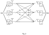
- Figure 2 depicts a schematic illustrating the nomenclature as used in the following.
- the base stations 120 of the system are considered as transmitters only, i.e. Tx1... Txk... TxK
- the mobile stations 150 are considered as receivers only, i.e. Rx1...Rxk...RxK, wherein letter k is the index of a transmitter or a receiver with 1...k...K. Accordingly we consider a system comprising a number of K transmitter receiver pairs that share a common radio resource.
- Each transmitter aims at conveying a data stream to its associated receiver, wherein a transmission originating from the k -th transmitter to the k -th receiver interferes with transmissions of the other pairs of transmitters and receivers, at receivers 1...k-1 and k+1...K as illustrated by the transfer functions h.
- the k -th receiver thus observers a superposition of signals from all transmitters but is interested only in the transmit signal from its associated transmitter.
- index I shall denote any transmitter or receiver station not associated with the k -th transmitter station.
- each transmitter is shown with two transmit antennas, the system shall not be limited by this, i.e. a transmitter may comprise a plurality of at least two or more transmit antennas.
- each k -th pair of transmitter and associated receiver is assigned a user utility function u1 ... uk ... uK.
- the overall performance of the system can be evaluated by considering the sum of all assigned utility functions, i.e. by evaluating a system utility function U being the sum of all functions u k .
- Each user utility function u k shall have two properties
- Typical examples of user utility functions reflect the signal-to-interference-plus-noise ratio (SINR) at the receiver, the achievable information rate or the bit error rate.
- SINR signal-to-interference-plus-noise ratio
- beamforming vector i.e. the complex valued scalar antenna weights
- the parameter to be adjusted in order to optimize the overall system performance is the parameter to be adjusted in order to optimize the overall system performance.
- the k -th transmitter we define as optimization variable the power gain vector x k that comprises all receive powers at all of the receivers, i.e. at the K receivers. Accordingly the l -th component of vector x k is denoted as x k,l and reflects the received power at the l -th receiver caused by the k -th transmitter.
- the optimization of the overall system i.e. the optimization of the system utility function U shall be performed decentralized, i.e. distributed.
- said central processing entity has knowledge of all necessary information about the system, e.g. channel information, and that can solve the optimization problem.
- each transmitter participates in optimizing the system utility function, wherein it is assumed that each k -th transmitter has knowledge about the channels between itself, i.e. the k -th's transmitter and each receiver 1... K , as well as the channel strength between the k -th's receiver and each transmitter 1... K , and wherein the transmitters are communicatively coupled for mutual information exchange.
- this assumption is realized by receivers 1..k -1, k+1...K, which report information reflecting channel state information to their respective associated base transmitter station. As described below said information is forwarded by the l -th base stations to the k -th base station, thus providing the channel state information between the k-th transmitter and the 1-th receiver, i.e. receivers 1...k-1, k+1...K.
- an upper bound Tmax on the largest possible update interval i.e., the largest possible time span between two successive updates of the power gain vector x k
- an upper bound Dmax on the largest backhaul delay are known to all transmitters. Therefore, the time is indexed by a discrete variable n which indexes all event of interest (i.e., an update step, a transmission or reception of a message via backhaul). Note that this (global) time variable is only needed for illustration and analysis purposes.
- Each transmitter uses a gradient method to iteratively update his local optimization variable x k , i.e. his local power gain vector x k .
- Each iteration step aims at increasing the value of the system utility function U . Therefore, in each iteration performed at a transmitter the optimization variable x k is amended in the direction of the steepest increase of function U .
- the information regarding the steepest increase of system utility function U is given by the gradient vector of system utility function U with respect to the optimization variable, i.e. the optimization vector x k .
- the gradient vector of the k -th transmitter consists of the partial derivatives du 1 / dx k, 1 ,...,du k / dx k,k du k / dx k,K .
- the components (i.e. partial derivatives) of this gradient vector must be computed by the individual transmitters, i.e. the l -th component of this gradient vector must be calculated by the l -th transmitter, and are exchanged thereafter between the transmitters. This is due to the local/exclusive knowledge of the individual transmitters, none of them has global knowledge. Only the l -th transmitter has the knowledge that is required for calculating the l -th component from the gradient vector of the k -transmitter. By selecting a system utility function that is differentiable, the partial derivatives can be calculated by using closed-form expressions.
- the components of the gradient vectors depend on the actual values of the optimization variable x 1 ,..., x k ,..., x K , i.e. the actual values of the power gain vectors that represent the current operating points of transmitters 1 ... K , these said gradient vector components have to be updated after each change in the optimization variables.
- the l -th transmitter needs the knowledge of all power gain vector components x 1,l ,...x K,l .
- the components of the optimization variables x 1 ... x k ... x K have to be mutually communicated from transmitter to transmitter, i.e. the k -th transmitter sends the l -th component x k,l of his power gain vector x k to the l -th transmitter. In this way each transmitter communicates each component of his power gain vector to the corresponding transmitter.
- the gradient vector components and the updated optimization values i.e. x 1 . ..x k-1 , x k+1 ... x K , are real-valued scalars, so the transmitters exchange real valued scalars.
- the amount of data to be communicated between the transmitters via the backhaul link is small, thus supporting a fast and effective implementation of the method and preventing clogging of the backhaul communication link.
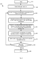
- FIG. 3 illustrates the method steps 300 iteratively performed by each transmitter at some arbitrary intervals and speed.
- all transmitters may keep radiating their signals (i.e. their transport streams) all the time, independently from the optimization process. From time to time, they may adapt their radiation by applying the new antenna weight vector that has been obtained from the (parallel ongoing) optimization process. Such an adaptation will yield an increased system utility.
- the following method steps are described from the viewpoint of the k -th transmitter that radiates a signal, wherein said radiated signal is received by the k- th receiver, i.e. the receiver associated with the radiating transmitter and by receivers 1...k-1 as well as receivers k+1...K, i.e. receivers associated with transmitters 1 ... l ... k-1 and k+1...K of cells adjoining the k -th cell.
- the first method step right after start 310 is the selection by at least the k -th transmitter of an initial gain vector x k in step 320.
- the k-th transmitter transfers all components l ⁇ k of the (current) power gain vector x k to the respective l- th transmitter.
- step 360 the k -th transmitter, i.e. each considered transmitter, transmits for each l ⁇ k , the calculated partial derivative du k / dx l,k to the respective l -th transmitter, i.e. to each other of the considered transmitters, via the backhaul link.
- step 370 i.e. when the k -th transmitter has received the partial derivatives du l / dx k,l of all other transmitters l , the transmitter updates his power gain vector x k . This update computation is described below.
- the transmitter checks in step 380 whether the algorithm converged. Depending on the largest possible backhaul communication delay Dmax and the largest possible inter-update interval Tmax, that is used by any transmitter in the network, the k -th transmitter checks whether the difference between its new calculated power gain vector and its power gain vector from (Dmax+Tmax) time instants before is smaller than a pre-specified threshold.
- the transmitter continues to use the antenna weights that have been calculated with respect to the latest power gain vector x k , and the loop ends, in block 390.
- step 330 i.e. the k -th transmitter transfers all components l ⁇ k of the power gain vector x k , obtained in step 370, to the respective l -th transmitter
- the k -th transmitter iterates (in arbitrary intervals, i.e. solely limited by the maximum inter-update period) through a loop until the algorithm converges, i.e. until the system utility function converges.
- step 370 the k -th transmitter may update his individual power gain vector x k before it has received the most recent partial derivatives.
- step 350 the transmitter may calculate the partial derivatives before it has received the most recent power gain components.
- the transmitter may perform computations based on outdated information. Some transmitters may perform their computations faster than others. The transmitters do not need to communicate to each other at each time instant thus they may exchange information at arbitrary intervals and operate asynchronously.
- the k -th transmitter adapts the components of vector x k one step in the direction of the gradient vector. Since the k -th transmitter does not have the information about the system utility function, the k -th transmitter cannot determine the optimal step size for the current update step, i.e. the k -th transmitter cannot determine the step size which provides the highest increase of the system utility function. To prevent an overshoot, i.e. due to a step size too large, the step size must be limited, wherein said limitation of the step size ensures that the system utility function always increases.
- the second derivative is finite for all relevant operation points. Furthermore we consider the delays in communication between the transmitters when communicating the power gain components/partial derivatives, and we consider the absolute value of the second (partial) derivative of the system utility function.
- the determination of the upper limit for the step size is determined as follows. Initially a function is defined that shall serve as the lower limit for the system utility function. For that purpose, a Taylor polynomial of second order using limits of the second partial derivatives is defined. Subsequently an error term is introduced into that function, which reflects the update step error caused by the use of outdated gradients.
- the error term is then approximated under deployment of the finite limits of the communication delays and the second-order partial derivatives, while ensuring that the resulting function is a valid lower limit for the system utility function.
- the algorithm uses defined step sizes and allows especially parallel, i.e. simultaneous, updating of all considered transmitters. Note that this is also true in case the transmitters operate on outdated information (i.e., power gains and partial derivatives) transmitted from other transmitters. As a consequence each transmitter may update his power gain values based on the available information provided by other transmitters, i.e. the transmitters may operate asynchronously.
- the beamforming vectors i.e. the antenna weights
- the antenna weights can be calculated based on the power gain vectors. Similar as in our considerations above, it is sufficient to consider the k -th transmitter only for reasons of symmetry.
- the optimization domain that is, the domain of the power gain vectors that are used as optimization variables.
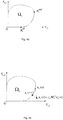
- the optimization domain (i.e. the feasible set of power gain vectors) of the k -th transmitter is given by the power gain region ⁇ k .
- the power gain area as depicted in the figure is two-dimensional. Note that figure 4 depicts two particular operating points, i.e. two particular power gain vectors:
- the area of the power gain is defined by the entity of transmitter correlation matrices being positive semi-definite and having a trace ⁇ 1. This last condition limits the maximum transmission power to 1. Accordingly for generating the power gain area, correlation matrices of arbitrary rank have been used. Consequently, the entity of ⁇ k is convex, which is required for projecting an updated power gain vector x k back to its valid range (i.e. constraint set), performed in step 370. Considering now that the transmitter always uses only a beamforming vector (i.e. antenna weight vector) for its radiation, then the corresponding correlation matrix is always of rank ⁇ 1.
- a beamforming vector i.e. antenna weight vector
- the power gain area may comprise operating points, which are not reachable by correlation matrices of rank 1, that is, it may contain power gain vectors that are not achievable by using beamforming vectors.
- all power gain vectors relevant for the sum utility problem i.e. the stationary operating points of our optimization problem, can be reached with correlation matrices of rank 1.
- ⁇ k which has been retrieved by relaxing the matrix rank, for the projection in step 370; wherein it is known that the power gain vector, which is obtained when the algorithm 300 has converged, is reachable by a beamforming vector.
- step 370 Before we can describe how to calculate the k-th beamforming vector based on the power gain vector, we have to illustrate a single update step as performed in step 370. More precisely, we have to illustrate the projection step performed within step 370.
- the k -th transmitter performed an update of his power gain vector x k at time index n .
- a projection, additionally scaled by matrix M k of vector x k ( n )+ ⁇ k M k -1 ⁇ ( n ) onto the convex compact entity of ⁇ k is required, confer figure 4b .
- the vector ⁇ k ( n ) denotes the vector of all acquired partial derivatives.
- this projection problem can NOT be solved by the entity of power gain vectors, i.e. this is not solvable in the power gain domain since it is unknown a priori which vectors belong to entity ⁇ k ; this can only be solved by try and error.
- said problem can be solved optimally using the entity of all signal correlation matrices; as noted above the entity of all possible signal correlation matrices defines the power gain area.
- the cost function of the projection problem i.e.
- the scaled Euclidian distance between vector x k ( n )+ ⁇ k M k -1 ⁇ k ( n ) and any reachable point of entity ⁇ k is reformulated using correlation matrix Q as the optimization variable for the projection problem, that leads to an equivalent convex optimization problem.
- Said optimization problem is a quadratic semi-definite optimization problem that can be solved by mathematical conventional tools, e.g. QSDP-0 for Matlab.
- Q* ( n +1) generates the sought-after power gain vector x k ( n +1,) i.e. the power gain vector that is the solution of update step 370.
- matrix Q* ( n +1) is of rank ⁇ 2.
- matrix Q* ( n +1) is of rank ⁇ 2.
- a beamforming vector generating at least the same sum utility.
- the user utility function u k being monotonous, it is sufficient to look for beamforming vectors causing less or the same amount of interference, and which generate at least the same load gain.
- we constrain to solutions, i.e. beamforming vectors, having a particular phase shift, namely the load signal, received by the intended receiver, that is given by h kk H w k must be real valued. Note that the optimum solution does not suffer from the phase shift, i.e. the phase shift does not influence the power gains.
Landscapes
- Engineering & Computer Science (AREA)
- Signal Processing (AREA)
- Computer Networks & Wireless Communication (AREA)
- Power Engineering (AREA)
- Quality & Reliability (AREA)
- Mobile Radio Communication Systems (AREA)
Claims (15)
- Mobiltelekommunikationssystem (100) umfassend eine Vielzahl von gekoppelten Funksendestationen Txl..Txk ..TxK, (120) K ≥ 2, die kommunikativ über Backhaul-Verbindungen (130) gekoppelt sind und die in aneinander angrenzenden Funkzellen 1 .. k .. K (110) angeordnet sind, wobei mindestens eine k-te Funksendestation Txk (120) zum Beamforming eines Funksignals (160) zu einer Empfängerstation Rxk (150) basierend auf einem k-ten Antennengewichtungsvektor wk eingerichtet ist, wobei jedes k-te Paar von Sendestation und zugeordneter Empfängerstation eine Benutzerdienstfunktion ul ... uk ... uK zugeordnet ist und eine Systemdienstfunktion U als die Summe aller Benutzerdienstfunktionen definiert ist, wobei die Optimierung der Systemdienstfunktion von einem verteilten Algorithmus durchgeführt wird,
dadurch gekennzeichnet, dass:zumindest die k-te Funksendestation Txk(120) eingerichtet ist zur Bestimmung des Antennengewichtungsvektors wk basierend auf einem optimierten k-ten Leistungsertragsvektor xk, der durch Iteration der folgenden Schritte bestimmt wird:- Senden jeder 1-ten, l≠k, Komponente des k-ten Leistungsertragsvektors xk,l an mindestens eine entsprechende l-te Funksendestation Txl (120),- Berechnen des k-ten Antennengewichtungsvektors wk basierend auf dem k-ten Leistungsertragsvektor xk und Senden des Funksignals (160) unter Verwendung des berechneten Antennengewichtungsvektors wk,- Berechnen partieller Ableitungen der k-ten Benutzerdienstfunktion duk/dxk,k und duk/dxl,k basierend auf einer k-ten Komponente jedes 1-ten Leistungsertragsvektors xl,k, der von der mindestens einen 1-ten Funksendestation Txl (120) empfangen wurde,- Übermitteln jeder l-ten partiellen Ableitung der berechneten k-ten Benutzerdienstfunktion duk/dxl,k an mindestens eine entsprechende l-te Funksendestation Txl (120), und- Aktualisieren des k-ten Leistungsertragsvektors xk basierend auf einer k-ten partiellen Ableitung jeder l-ten Benutzerdienstfunktion dul/dxk,l, die von der mindestens einen entsprechenden l-ten Funksendestation Txl (120) empfangen worden ist, basierend auf einem Optimierungsalgorithmus mit einer begrenzten Schrittgröße, wobei die k-te Funksendestation und die 1-te Funksendestation weiterhin zum asynchronen Austausch der partiellen Ableitungen und des Leistungsertrags über Backhaul-Verbindungen eingerichtet sind. - Mobiltelekommunikationssystem (100) nach Anspruch 1, wobei die begrenzte Schrittgröße durch die folgenden Schritte bestimmt wird:- Bestimmen eines Taylorpolynoms zweiter Ordnung unter Verwendung von Grenzen zweiter partieller Ableitungen der Systemdienstfunktion U,- Annähern eines Fehlerterms für einen aktualisierten Schrittfehler, der durch veraltete empfangene Ableitungen der Benutzerdienstfunktionen du/dx verursacht wurde, durch Anwendung endlicher Grenzen von Kommunikationsverzögerungen und besagter zweiter Ableitungen, und- Umwandeln der Annäherung in eine quadratische Funktion zum Berechnen einer Schrittgrößengrenze.
- Mobiltelekommunikationssystem (100) nach einem der vorhergehenden Ansprüche, wobei die Benutzerdienstfunktionen u mindestens eines aus dem Signal-zu-Interferenz plus Rauschen-Verhältnis oder der erreichbaren Informationsrate oder der Bitfehlerrate zwischen einem Paar einer Funksendestationen Tx (120) und einem zugeordneten Empfänger Rx (150) wiedergibt.
- Mobiltelekommunikationssystem (100) nach einem der vorhergehenden Ansprüche, wobei ein initialer Leistungsertragsvektor wk vor einer ersten Iteration gewählt wird.
- Mobiltelekommunikationssystem (100) nach einem der vorhergehenden Ansprüche, wobei überprüft wird, ob der Optimierungsalgorithmus konvergiert ist und, falls ja, die Iteration beendet wird.
- Mobiltelekommunikationssystem (100) nach einem der vorhergehenden Ansprüche, wobei die Funksendestationen Tx (120) Basisstationen eines Mobilfunktelekommunikationsnetzwerks sind, die kommunikativ über ein Funkzugangsnetzwerk des Mobilfunktelekommunikationsnetzwerks gekoppelt sind.
- Mobiltelekommunikationssystem (100) nach einem der vorhergehenden Ansprüche, wobei mindestens ein k-ter Empfänger Rxk (150) mit der k-ten Funksendestation Txk (120) gekoppelt ist, wobei mindestens ein l-ter Empfänger Rxl (150) mit der mindestens einen 1-ten Funksendestation Txl (120) gekoppelt ist, wobei zumindest der mindestens eine 1-te Empfänger Rxl (150) dazu eingerichtet ist, der mindestens einen 1-ten Funksendestation Txl (120) eine Empfangsleistung des Funksignals (160), welches von der k-ten Funksendestation Txk (120) ausgestrahlt wurde, zu kommunizieren.
- Mobiltelekommunikationssystem (100) nach einem der vorhergehenden Ansprüche, wobei zumindest die k-te Funksendestation weiterhin zur Durchführung der Schritte in einer Schleife eingerichtet ist.
- Verfahren zur Optimierung von Datenübermittlung in einem Mobiltelekommunikationssystem (100), welches eine Vielzahl von gekoppelten Funksendestationen Txl..Txk ..TxK, (120) K ≥ 2 umfasst, die kommunikativ über Backhaul-Verbindungen (130) gekoppelt sind und die in aneinander angrenzenden Funkzellen 1 ... K (110) angeordnet sind, wobei mindestens eine k-te Funksendestation Txk (120) zum Beamforming eines Funksignals (160) zu einer Empfängerstation Rxk (150) basierend auf einem k-ten Antennengewichtungsvektor wk eingerichtet ist, wobei jedes k-te Paar von Sendestation und zugeordneter Empfängerstation eine Benutzerdienstfunktion ul ... uk ... uk zugeordnet ist und eine Systemdienstfunktion U als die Summe aller Benutzerdienstfunktionen definiert ist, wobei die Optimierung der Systemdienstfunktion von einem verteilten Algorithmus durchgeführt wird,
dadurch gekennzeichnet, dass:zumindest die k-te Funksendestation Txk (120) eingerichtet ist zur Bestimmung des Antennengewichtungsvektors wk basierend auf einem optimierten k-ten Leistungsertragsvektor xk, der durch Iteration der folgenden Schritte bestimmt wird:- Senden jeder 1-ten, l≠k, Komponente des k-ten Leistungsertragsvektors xk,l an mindestens eine entsprechende l-te Funksendestation Txl (120),- Berechnen des k-ten Antennengewichtungsvektors wk basierend auf dem k-ten Leistungsertragsvektor xk und Senden des Funksignals (160) unter Verwendung des berechneten Antennengewichtungsvektors wk,- Berechnen partieller Ableitungen der k-ten Benutzerdienstfunktion duk/dxk,k und duk/dxl,k basierend auf einer k-ten Komponente jedes 1-ten Leistungsertragsvektors xl,k, der von der mindestens einen l-ten Funksendestation Txl (120) empfangen wurde,- Übermitteln jeder 1-ten partiellen Ableitung der berechneten k-ten Benutzerdienstfunktion duk/dxl,k an die mindestens eine entsprechende l-te Funksendestation Txl (120), und- Aktualisieren des k-ten Leistungsertragsvektors xk basierend auf einer k-ten partiellen Ableitung jeder 1-ten Benutzerdienstfunktion dul/dxk,l, die von der mindestens einen entsprechenden 1-ten Funksendestation Txl (120) empfangen worden ist, basierend auf einem Optimierungsalgorithmus mit einer begrenzten Schrittgröße, wobei die k-te Funksendestation und die 1-te Funksendestation weiterhin zum asynchronen Austausch der partiellen Ableitungen und des Leistungsertrags über Backhaul-Verbindungen eingerichtet sind. - Verfahren nach Anspruch 9, wobei die begrenzte Schrittgröße durch die folgenden Schritte bestimmt wird:- Bestimmen eines Taylorpolynoms zweiter Ordnung unter Verwendung von Grenzen zweiter partieller Ableitungen der Systemdienstfunktion U,- Annähern eines Fehlerterms für einen aktualisierten Schrittfehler, der durch veraltete empfangene Ableitungen der Benutzerdienstfunktionen du/dx verursacht wurde, durch Anwendung endlicher Grenzen von Kommunikationsverzögerungen und besagter zweiter Ableitungen, und- Umwandeln der Annäherung in eine quadratische Funktion zum Berechnen einer Schrittgrößengrenze.
- Verfahren nach einem der Ansprüche 9 bis 10, wobei die Benutzerdienstfunktionen u mindestens eines aus dem Signal-zu-Interferenz plus Rauschen-Verhältnis oder der erreichbaren Informationsrate oder der Bitfehlerrate zwischen einem Paar einer Funksendestationen Tx(120) und einem zugeordneten Empfänger Rx (150) wiedergibt.
- Verfahren nach einem der Ansprüche 9 bis 11, wobei ein initialer Leistungsertragsvektor wk vor der ersten Iteration gewählt wird.
- Verfahren nach einem der Ansprüche 9 bis 12, wobei überprüft wird, ob der Optimierungsalgorithmus konvergiert ist und, falls ja, die Iteration beendet wird.
- Verfahren nach einem der Ansprüche 9 bis 13, wobei die Funksendestationen Tx (120) Basisstationen eines Mobilfunktelekommunikationsnetzwerks sind, die kommunikativ über ein Funkzugangsnetzwerk des Mobilfunktelekommunikationsnetzwerks gekoppelt sind.
- Verfahren nach einem der Ansprüche 9 bis 14, wobei die Verfahrensschritte in einer Schleife durchgeführt werden.
Priority Applications (2)
| Application Number | Priority Date | Filing Date | Title |
|---|---|---|---|
| EP14163758.7A EP2930858B1 (de) | 2014-04-07 | 2014-04-07 | Telekommunikationssystem und Verfahren mit Verwendung verteilter asynchroner Strahlformung in MISO-Interferenzkanälen |
| US14/680,691 US9516649B2 (en) | 2014-04-07 | 2015-04-07 | Telecommunication system and method using distributed asynchronous beamforming in the MISO interference channel |
Applications Claiming Priority (1)
| Application Number | Priority Date | Filing Date | Title |
|---|---|---|---|
| EP14163758.7A EP2930858B1 (de) | 2014-04-07 | 2014-04-07 | Telekommunikationssystem und Verfahren mit Verwendung verteilter asynchroner Strahlformung in MISO-Interferenzkanälen |
Publications (2)
| Publication Number | Publication Date |
|---|---|
| EP2930858A1 EP2930858A1 (de) | 2015-10-14 |
| EP2930858B1 true EP2930858B1 (de) | 2017-06-21 |
Family
ID=50440540
Family Applications (1)
| Application Number | Title | Priority Date | Filing Date |
|---|---|---|---|
| EP14163758.7A Active EP2930858B1 (de) | 2014-04-07 | 2014-04-07 | Telekommunikationssystem und Verfahren mit Verwendung verteilter asynchroner Strahlformung in MISO-Interferenzkanälen |
Country Status (2)
| Country | Link |
|---|---|
| US (1) | US9516649B2 (de) |
| EP (1) | EP2930858B1 (de) |
Families Citing this family (2)
| Publication number | Priority date | Publication date | Assignee | Title |
|---|---|---|---|---|
| KR102188306B1 (ko) * | 2014-09-02 | 2020-12-08 | 삼성전자주식회사 | 통신 시스템에서 패킷 전송 방법 및 장치 |
| EP3939367B1 (de) * | 2019-03-13 | 2026-02-11 | Nokia Technologies OY | Anpassung von strahlformungsprofilen |
Family Cites Families (3)
| Publication number | Priority date | Publication date | Assignee | Title |
|---|---|---|---|---|
| US6956907B2 (en) * | 2001-10-15 | 2005-10-18 | Qualcomm, Incorporated | Method and apparatus for determining power allocation in a MIMO communication system |
| KR100946930B1 (ko) * | 2006-07-31 | 2010-03-09 | 삼성전자주식회사 | 통신 시스템에서 송신 안테나 이득 제어 방법 및 장치 |
| US8193975B2 (en) * | 2008-11-12 | 2012-06-05 | Atc Technologies | Iterative antenna beam forming systems/methods |
-
2014
- 2014-04-07 EP EP14163758.7A patent/EP2930858B1/de active Active
-
2015
- 2015-04-07 US US14/680,691 patent/US9516649B2/en active Active
Also Published As
| Publication number | Publication date |
|---|---|
| EP2930858A1 (de) | 2015-10-14 |
| US9516649B2 (en) | 2016-12-06 |
| US20150289248A1 (en) | 2015-10-08 |
Similar Documents
| Publication | Publication Date | Title |
|---|---|---|
| CN112804695B (zh) | 可重构智能表面辅助的无线通信方法及装置 | |
| EP2732654B1 (de) | Verteilte strahlenauswahl für mobilgerätekommunikation | |
| CN109891963B (zh) | 用于三维多输入多输出通信系统中波束赋形的参考信号的系统和方法 | |
| US9743397B2 (en) | Reduced-size message pass in factor graphs for wireless communications networks | |
| US12028139B2 (en) | Wireless telecommunications network including a multi-layer transmissive reconfigurable intelligent surface | |
| CN111163511A (zh) | 智能反射表面辅助的毫米波通信中延迟受限的上行功率分配方法 | |
| TWI410064B (zh) | 在無線通訊網路中使用的終端機與方法 | |
| CN114631267A (zh) | 针对多传输接收点/面板和无小区多输入多输出的信道状态信息开销减少 | |
| EP3430830B1 (de) | Steuerknoten und verfahren dafür | |
| JP6663256B2 (ja) | 無線通信システム及び管理装置 | |
| US20200382196A1 (en) | Method for detecting beam failure event by base station in wireless network | |
| US8849207B2 (en) | Method, apparatus and system for choosing a parameter setting from a set of available parameter settings | |
| US20250192828A1 (en) | Method and apparatus for beam configuration of reconfigurable intelligent surface in communication system | |
| CN113676234A (zh) | 具有长传播延迟的ntn中的增强csi反馈 | |
| KR20180027748A (ko) | 다중 입출력 시스템에서 빔포밍을 위한 방법 및 장치 | |
| EP2930858B1 (de) | Telekommunikationssystem und Verfahren mit Verwendung verteilter asynchroner Strahlformung in MISO-Interferenzkanälen | |
| US11664867B2 (en) | Computation of beamforming parameters | |
| US12250037B2 (en) | Beamforming setting selection | |
| Amudala et al. | URLLC in D2D underlaid massive MIMO systems: Receiver design and GEE optimization | |
| Li et al. | Multi-RIS aided multi-user mmWave MIMO system modelled by Matérn hard-core point processes | |
| EP4120579B1 (de) | Interferenzbewusste eigenstrahlformung basierend auf statistiken zweiter ordnung | |
| CN119449103A (zh) | 信息传输方法、装置及存储介质 | |
| US20250150180A1 (en) | Calculating interference suppression weights and processing signals | |
| US20220346143A1 (en) | Transmission Beam Selection | |
| EP2924888A1 (de) | HF-Streckenverwaltung für energieeffiziente zelluläre Netzwerke |
Legal Events
| Date | Code | Title | Description |
|---|---|---|---|
| PUAI | Public reference made under article 153(3) epc to a published international application that has entered the european phase |
Free format text: ORIGINAL CODE: 0009012 |
|
| AK | Designated contracting states |
Kind code of ref document: A1 Designated state(s): AL AT BE BG CH CY CZ DE DK EE ES FI FR GB GR HR HU IE IS IT LI LT LU LV MC MK MT NL NO PL PT RO RS SE SI SK SM TR |
|
| AX | Request for extension of the european patent |
Extension state: BA ME |
|
| 17P | Request for examination filed |
Effective date: 20151104 |
|
| RBV | Designated contracting states (corrected) |
Designated state(s): AL AT BE BG CH CY CZ DE DK EE ES FI FR GB GR HR HU IE IS IT LI LT LU LV MC MK MT NL NO PL PT RO RS SE SI SK SM TR |
|
| GRAP | Despatch of communication of intention to grant a patent |
Free format text: ORIGINAL CODE: EPIDOSNIGR1 |
|
| RIC1 | Information provided on ipc code assigned before grant |
Ipc: H04B 7/06 20060101ALI20170102BHEP Ipc: H04B 7/02 20170101AFI20170102BHEP Ipc: H04B 7/04 20170101ALI20170102BHEP Ipc: H04L 5/00 20060101ALI20170102BHEP Ipc: H04W 52/24 20090101ALI20170102BHEP Ipc: H04W 72/04 20090101ALI20170102BHEP |
|
| INTG | Intention to grant announced |
Effective date: 20170124 |
|
| GRAS | Grant fee paid |
Free format text: ORIGINAL CODE: EPIDOSNIGR3 |
|
| GRAA | (expected) grant |
Free format text: ORIGINAL CODE: 0009210 |
|
| AK | Designated contracting states |
Kind code of ref document: B1 Designated state(s): AL AT BE BG CH CY CZ DE DK EE ES FI FR GB GR HR HU IE IS IT LI LT LU LV MC MK MT NL NO PL PT RO RS SE SI SK SM TR |
|
| REG | Reference to a national code |
Ref country code: GB Ref legal event code: FG4D |
|
| REG | Reference to a national code |
Ref country code: CH Ref legal event code: EP |
|
| REG | Reference to a national code |
Ref country code: IE Ref legal event code: FG4D |
|
| REG | Reference to a national code |
Ref country code: AT Ref legal event code: REF Ref document number: 903786 Country of ref document: AT Kind code of ref document: T Effective date: 20170715 |
|
| REG | Reference to a national code |
Ref country code: DE Ref legal event code: R096 Ref document number: 602014010899 Country of ref document: DE |
|
| REG | Reference to a national code |
Ref country code: NL Ref legal event code: MP Effective date: 20170621 |
|
| PG25 | Lapsed in a contracting state [announced via postgrant information from national office to epo] |
Ref country code: LT Free format text: LAPSE BECAUSE OF FAILURE TO SUBMIT A TRANSLATION OF THE DESCRIPTION OR TO PAY THE FEE WITHIN THE PRESCRIBED TIME-LIMIT Effective date: 20170621 Ref country code: GR Free format text: LAPSE BECAUSE OF FAILURE TO SUBMIT A TRANSLATION OF THE DESCRIPTION OR TO PAY THE FEE WITHIN THE PRESCRIBED TIME-LIMIT Effective date: 20170922 Ref country code: NO Free format text: LAPSE BECAUSE OF FAILURE TO SUBMIT A TRANSLATION OF THE DESCRIPTION OR TO PAY THE FEE WITHIN THE PRESCRIBED TIME-LIMIT Effective date: 20170921 Ref country code: FI Free format text: LAPSE BECAUSE OF FAILURE TO SUBMIT A TRANSLATION OF THE DESCRIPTION OR TO PAY THE FEE WITHIN THE PRESCRIBED TIME-LIMIT Effective date: 20170621 Ref country code: HR Free format text: LAPSE BECAUSE OF FAILURE TO SUBMIT A TRANSLATION OF THE DESCRIPTION OR TO PAY THE FEE WITHIN THE PRESCRIBED TIME-LIMIT Effective date: 20170621 |
|
| REG | Reference to a national code |
Ref country code: LT Ref legal event code: MG4D |
|
| REG | Reference to a national code |
Ref country code: AT Ref legal event code: MK05 Ref document number: 903786 Country of ref document: AT Kind code of ref document: T Effective date: 20170621 |
|
| PG25 | Lapsed in a contracting state [announced via postgrant information from national office to epo] |
Ref country code: BG Free format text: LAPSE BECAUSE OF FAILURE TO SUBMIT A TRANSLATION OF THE DESCRIPTION OR TO PAY THE FEE WITHIN THE PRESCRIBED TIME-LIMIT Effective date: 20170921 Ref country code: LV Free format text: LAPSE BECAUSE OF FAILURE TO SUBMIT A TRANSLATION OF THE DESCRIPTION OR TO PAY THE FEE WITHIN THE PRESCRIBED TIME-LIMIT Effective date: 20170621 Ref country code: SE Free format text: LAPSE BECAUSE OF FAILURE TO SUBMIT A TRANSLATION OF THE DESCRIPTION OR TO PAY THE FEE WITHIN THE PRESCRIBED TIME-LIMIT Effective date: 20170621 Ref country code: NL Free format text: LAPSE BECAUSE OF FAILURE TO SUBMIT A TRANSLATION OF THE DESCRIPTION OR TO PAY THE FEE WITHIN THE PRESCRIBED TIME-LIMIT Effective date: 20170621 Ref country code: RS Free format text: LAPSE BECAUSE OF FAILURE TO SUBMIT A TRANSLATION OF THE DESCRIPTION OR TO PAY THE FEE WITHIN THE PRESCRIBED TIME-LIMIT Effective date: 20170621 |
|
| PG25 | Lapsed in a contracting state [announced via postgrant information from national office to epo] |
Ref country code: SK Free format text: LAPSE BECAUSE OF FAILURE TO SUBMIT A TRANSLATION OF THE DESCRIPTION OR TO PAY THE FEE WITHIN THE PRESCRIBED TIME-LIMIT Effective date: 20170621 Ref country code: CZ Free format text: LAPSE BECAUSE OF FAILURE TO SUBMIT A TRANSLATION OF THE DESCRIPTION OR TO PAY THE FEE WITHIN THE PRESCRIBED TIME-LIMIT Effective date: 20170621 Ref country code: RO Free format text: LAPSE BECAUSE OF FAILURE TO SUBMIT A TRANSLATION OF THE DESCRIPTION OR TO PAY THE FEE WITHIN THE PRESCRIBED TIME-LIMIT Effective date: 20170621 Ref country code: EE Free format text: LAPSE BECAUSE OF FAILURE TO SUBMIT A TRANSLATION OF THE DESCRIPTION OR TO PAY THE FEE WITHIN THE PRESCRIBED TIME-LIMIT Effective date: 20170621 Ref country code: AT Free format text: LAPSE BECAUSE OF FAILURE TO SUBMIT A TRANSLATION OF THE DESCRIPTION OR TO PAY THE FEE WITHIN THE PRESCRIBED TIME-LIMIT Effective date: 20170621 |
|
| PG25 | Lapsed in a contracting state [announced via postgrant information from national office to epo] |
Ref country code: IT Free format text: LAPSE BECAUSE OF FAILURE TO SUBMIT A TRANSLATION OF THE DESCRIPTION OR TO PAY THE FEE WITHIN THE PRESCRIBED TIME-LIMIT Effective date: 20170621 Ref country code: IS Free format text: LAPSE BECAUSE OF FAILURE TO SUBMIT A TRANSLATION OF THE DESCRIPTION OR TO PAY THE FEE WITHIN THE PRESCRIBED TIME-LIMIT Effective date: 20171021 Ref country code: ES Free format text: LAPSE BECAUSE OF FAILURE TO SUBMIT A TRANSLATION OF THE DESCRIPTION OR TO PAY THE FEE WITHIN THE PRESCRIBED TIME-LIMIT Effective date: 20170621 Ref country code: SM Free format text: LAPSE BECAUSE OF FAILURE TO SUBMIT A TRANSLATION OF THE DESCRIPTION OR TO PAY THE FEE WITHIN THE PRESCRIBED TIME-LIMIT Effective date: 20170621 Ref country code: PL Free format text: LAPSE BECAUSE OF FAILURE TO SUBMIT A TRANSLATION OF THE DESCRIPTION OR TO PAY THE FEE WITHIN THE PRESCRIBED TIME-LIMIT Effective date: 20170621 |
|
| REG | Reference to a national code |
Ref country code: DE Ref legal event code: R097 Ref document number: 602014010899 Country of ref document: DE |
|
| REG | Reference to a national code |
Ref country code: FR Ref legal event code: PLFP Year of fee payment: 5 |
|
| PLBE | No opposition filed within time limit |
Free format text: ORIGINAL CODE: 0009261 |
|
| STAA | Information on the status of an ep patent application or granted ep patent |
Free format text: STATUS: NO OPPOSITION FILED WITHIN TIME LIMIT |
|
| PG25 | Lapsed in a contracting state [announced via postgrant information from national office to epo] |
Ref country code: DK Free format text: LAPSE BECAUSE OF FAILURE TO SUBMIT A TRANSLATION OF THE DESCRIPTION OR TO PAY THE FEE WITHIN THE PRESCRIBED TIME-LIMIT Effective date: 20170621 |
|
| 26N | No opposition filed |
Effective date: 20180322 |
|
| PG25 | Lapsed in a contracting state [announced via postgrant information from national office to epo] |
Ref country code: SI Free format text: LAPSE BECAUSE OF FAILURE TO SUBMIT A TRANSLATION OF THE DESCRIPTION OR TO PAY THE FEE WITHIN THE PRESCRIBED TIME-LIMIT Effective date: 20170621 |
|
| PG25 | Lapsed in a contracting state [announced via postgrant information from national office to epo] |
Ref country code: MC Free format text: LAPSE BECAUSE OF FAILURE TO SUBMIT A TRANSLATION OF THE DESCRIPTION OR TO PAY THE FEE WITHIN THE PRESCRIBED TIME-LIMIT Effective date: 20170621 |
|
| REG | Reference to a national code |
Ref country code: CH Ref legal event code: PL |
|
| REG | Reference to a national code |
Ref country code: BE Ref legal event code: MM Effective date: 20180430 |
|
| REG | Reference to a national code |
Ref country code: IE Ref legal event code: MM4A |
|
| PG25 | Lapsed in a contracting state [announced via postgrant information from national office to epo] |
Ref country code: LU Free format text: LAPSE BECAUSE OF NON-PAYMENT OF DUE FEES Effective date: 20180407 |
|
| PG25 | Lapsed in a contracting state [announced via postgrant information from national office to epo] |
Ref country code: CH Free format text: LAPSE BECAUSE OF NON-PAYMENT OF DUE FEES Effective date: 20180430 Ref country code: LI Free format text: LAPSE BECAUSE OF NON-PAYMENT OF DUE FEES Effective date: 20180430 Ref country code: BE Free format text: LAPSE BECAUSE OF NON-PAYMENT OF DUE FEES Effective date: 20180430 |
|
| PG25 | Lapsed in a contracting state [announced via postgrant information from national office to epo] |
Ref country code: IE Free format text: LAPSE BECAUSE OF NON-PAYMENT OF DUE FEES Effective date: 20180407 |
|
| PG25 | Lapsed in a contracting state [announced via postgrant information from national office to epo] |
Ref country code: MT Free format text: LAPSE BECAUSE OF NON-PAYMENT OF DUE FEES Effective date: 20180407 |
|
| PG25 | Lapsed in a contracting state [announced via postgrant information from national office to epo] |
Ref country code: TR Free format text: LAPSE BECAUSE OF FAILURE TO SUBMIT A TRANSLATION OF THE DESCRIPTION OR TO PAY THE FEE WITHIN THE PRESCRIBED TIME-LIMIT Effective date: 20170621 |
|
| PG25 | Lapsed in a contracting state [announced via postgrant information from national office to epo] |
Ref country code: PT Free format text: LAPSE BECAUSE OF FAILURE TO SUBMIT A TRANSLATION OF THE DESCRIPTION OR TO PAY THE FEE WITHIN THE PRESCRIBED TIME-LIMIT Effective date: 20170621 |
|
| PG25 | Lapsed in a contracting state [announced via postgrant information from national office to epo] |
Ref country code: MK Free format text: LAPSE BECAUSE OF NON-PAYMENT OF DUE FEES Effective date: 20170621 Ref country code: HU Free format text: LAPSE BECAUSE OF FAILURE TO SUBMIT A TRANSLATION OF THE DESCRIPTION OR TO PAY THE FEE WITHIN THE PRESCRIBED TIME-LIMIT; INVALID AB INITIO Effective date: 20140407 Ref country code: CY Free format text: LAPSE BECAUSE OF FAILURE TO SUBMIT A TRANSLATION OF THE DESCRIPTION OR TO PAY THE FEE WITHIN THE PRESCRIBED TIME-LIMIT Effective date: 20170621 |
|
| PG25 | Lapsed in a contracting state [announced via postgrant information from national office to epo] |
Ref country code: AL Free format text: LAPSE BECAUSE OF FAILURE TO SUBMIT A TRANSLATION OF THE DESCRIPTION OR TO PAY THE FEE WITHIN THE PRESCRIBED TIME-LIMIT Effective date: 20170621 |
|
| P01 | Opt-out of the competence of the unified patent court (upc) registered |
Effective date: 20230717 |
|
| PGFP | Annual fee paid to national office [announced via postgrant information from national office to epo] |
Ref country code: DE Payment date: 20250422 Year of fee payment: 12 |
|
| PGFP | Annual fee paid to national office [announced via postgrant information from national office to epo] |
Ref country code: GB Payment date: 20250423 Year of fee payment: 12 |
|
| PGFP | Annual fee paid to national office [announced via postgrant information from national office to epo] |
Ref country code: FR Payment date: 20250425 Year of fee payment: 12 |