EP2930799B1 - Angeordneter glasfaserverstärker unter verwendung von bandförmiger erbiumdotierter faser - Google Patents
Angeordneter glasfaserverstärker unter verwendung von bandförmiger erbiumdotierter faser Download PDFInfo
- Publication number
- EP2930799B1 EP2930799B1 EP15163174.4A EP15163174A EP2930799B1 EP 2930799 B1 EP2930799 B1 EP 2930799B1 EP 15163174 A EP15163174 A EP 15163174A EP 2930799 B1 EP2930799 B1 EP 2930799B1
- Authority
- EP
- European Patent Office
- Prior art keywords
- erbium
- doped
- edf
- gain
- ribbon
- Prior art date
- Legal status (The legal status is an assumption and is not a legal conclusion. Google has not performed a legal analysis and makes no representation as to the accuracy of the status listed.)
- Active
Links
Images



Classifications
-
- H—ELECTRICITY
- H01—ELECTRIC ELEMENTS
- H01S—DEVICES USING THE PROCESS OF LIGHT AMPLIFICATION BY STIMULATED EMISSION OF RADIATION [LASER] TO AMPLIFY OR GENERATE LIGHT; DEVICES USING STIMULATED EMISSION OF ELECTROMAGNETIC RADIATION IN WAVE RANGES OTHER THAN OPTICAL
- H01S3/00—Lasers, i.e. devices using stimulated emission of electromagnetic radiation in the infrared, visible or ultraviolet wave range
- H01S3/05—Construction or shape of optical resonators; Accommodation of active medium therein; Shape of active medium
- H01S3/06—Construction or shape of active medium
- H01S3/063—Waveguide lasers, i.e. whereby the dimensions of the waveguide are of the order of the light wavelength
- H01S3/067—Fibre lasers
- H01S3/06754—Fibre amplifiers
-
- H—ELECTRICITY
- H01—ELECTRIC ELEMENTS
- H01S—DEVICES USING THE PROCESS OF LIGHT AMPLIFICATION BY STIMULATED EMISSION OF RADIATION [LASER] TO AMPLIFY OR GENERATE LIGHT; DEVICES USING STIMULATED EMISSION OF ELECTROMAGNETIC RADIATION IN WAVE RANGES OTHER THAN OPTICAL
- H01S3/00—Lasers, i.e. devices using stimulated emission of electromagnetic radiation in the infrared, visible or ultraviolet wave range
- H01S3/05—Construction or shape of optical resonators; Accommodation of active medium therein; Shape of active medium
- H01S3/06—Construction or shape of active medium
- H01S3/063—Waveguide lasers, i.e. whereby the dimensions of the waveguide are of the order of the light wavelength
- H01S3/067—Fibre lasers
- H01S3/06708—Constructional details of the fibre, e.g. compositions, cross-section, shape or tapering
- H01S3/06729—Peculiar transverse fibre profile
- H01S3/06737—Fibre having multiple non-coaxial cores, e.g. multiple active cores or separate cores for pump and gain
-
- G—PHYSICS
- G02—OPTICS
- G02B—OPTICAL ELEMENTS, SYSTEMS OR APPARATUS
- G02B6/00—Light guides; Structural details of arrangements comprising light guides and other optical elements, e.g. couplings
- G02B6/02—Optical fibres with cladding with or without a coating
- G02B6/036—Optical fibres with cladding with or without a coating core or cladding comprising multiple layers
-
- G—PHYSICS
- G02—OPTICS
- G02B—OPTICAL ELEMENTS, SYSTEMS OR APPARATUS
- G02B6/00—Light guides; Structural details of arrangements comprising light guides and other optical elements, e.g. couplings
- G02B6/44—Mechanical structures for providing tensile strength and external protection for fibres, e.g. optical transmission cables
- G02B6/4401—Optical cables
- G02B6/4403—Optical cables with ribbon structure
- G02B6/4404—Multi-podded
-
- H—ELECTRICITY
- H01—ELECTRIC ELEMENTS
- H01S—DEVICES USING THE PROCESS OF LIGHT AMPLIFICATION BY STIMULATED EMISSION OF RADIATION [LASER] TO AMPLIFY OR GENERATE LIGHT; DEVICES USING STIMULATED EMISSION OF ELECTROMAGNETIC RADIATION IN WAVE RANGES OTHER THAN OPTICAL
- H01S3/00—Lasers, i.e. devices using stimulated emission of electromagnetic radiation in the infrared, visible or ultraviolet wave range
- H01S3/09—Processes or apparatus for excitation, e.g. pumping
- H01S3/091—Processes or apparatus for excitation, e.g. pumping using optical pumping
- H01S3/094—Processes or apparatus for excitation, e.g. pumping using optical pumping by coherent light
- H01S3/094003—Processes or apparatus for excitation, e.g. pumping using optical pumping by coherent light the pumped medium being a fibre
-
- H—ELECTRICITY
- H01—ELECTRIC ELEMENTS
- H01S—DEVICES USING THE PROCESS OF LIGHT AMPLIFICATION BY STIMULATED EMISSION OF RADIATION [LASER] TO AMPLIFY OR GENERATE LIGHT; DEVICES USING STIMULATED EMISSION OF ELECTROMAGNETIC RADIATION IN WAVE RANGES OTHER THAN OPTICAL
- H01S3/00—Lasers, i.e. devices using stimulated emission of electromagnetic radiation in the infrared, visible or ultraviolet wave range
- H01S3/23—Arrangements of two or more lasers not provided for in groups H01S3/02 - H01S3/22, e.g. tandem arrangements of separate active media
- H01S3/2383—Parallel arrangements
- H01S3/2391—Parallel arrangements emitting at different wavelengths
-
- H—ELECTRICITY
- H01—ELECTRIC ELEMENTS
- H01S—DEVICES USING THE PROCESS OF LIGHT AMPLIFICATION BY STIMULATED EMISSION OF RADIATION [LASER] TO AMPLIFY OR GENERATE LIGHT; DEVICES USING STIMULATED EMISSION OF ELECTROMAGNETIC RADIATION IN WAVE RANGES OTHER THAN OPTICAL
- H01S3/00—Lasers, i.e. devices using stimulated emission of electromagnetic radiation in the infrared, visible or ultraviolet wave range
- H01S3/005—Optical devices external to the laser cavity, specially adapted for lasers, e.g. for homogenisation of the beam or for manipulating laser pulses, e.g. pulse shaping
- H01S3/0064—Anti-reflection devices, e.g. optical isolaters
-
- H—ELECTRICITY
- H01—ELECTRIC ELEMENTS
- H01S—DEVICES USING THE PROCESS OF LIGHT AMPLIFICATION BY STIMULATED EMISSION OF RADIATION [LASER] TO AMPLIFY OR GENERATE LIGHT; DEVICES USING STIMULATED EMISSION OF ELECTROMAGNETIC RADIATION IN WAVE RANGES OTHER THAN OPTICAL
- H01S3/00—Lasers, i.e. devices using stimulated emission of electromagnetic radiation in the infrared, visible or ultraviolet wave range
- H01S3/005—Optical devices external to the laser cavity, specially adapted for lasers, e.g. for homogenisation of the beam or for manipulating laser pulses, e.g. pulse shaping
- H01S3/0078—Frequency filtering
-
- H—ELECTRICITY
- H01—ELECTRIC ELEMENTS
- H01S—DEVICES USING THE PROCESS OF LIGHT AMPLIFICATION BY STIMULATED EMISSION OF RADIATION [LASER] TO AMPLIFY OR GENERATE LIGHT; DEVICES USING STIMULATED EMISSION OF ELECTROMAGNETIC RADIATION IN WAVE RANGES OTHER THAN OPTICAL
- H01S3/00—Lasers, i.e. devices using stimulated emission of electromagnetic radiation in the infrared, visible or ultraviolet wave range
- H01S3/05—Construction or shape of optical resonators; Accommodation of active medium therein; Shape of active medium
- H01S3/06—Construction or shape of active medium
- H01S3/063—Waveguide lasers, i.e. whereby the dimensions of the waveguide are of the order of the light wavelength
- H01S3/067—Fibre lasers
- H01S3/06754—Fibre amplifiers
- H01S3/06762—Fibre amplifiers having a specific amplification band
- H01S3/06766—C-band amplifiers, i.e. amplification in the range of about 1530 nm to 1560 nm
-
- H—ELECTRICITY
- H01—ELECTRIC ELEMENTS
- H01S—DEVICES USING THE PROCESS OF LIGHT AMPLIFICATION BY STIMULATED EMISSION OF RADIATION [LASER] TO AMPLIFY OR GENERATE LIGHT; DEVICES USING STIMULATED EMISSION OF ELECTROMAGNETIC RADIATION IN WAVE RANGES OTHER THAN OPTICAL
- H01S3/00—Lasers, i.e. devices using stimulated emission of electromagnetic radiation in the infrared, visible or ultraviolet wave range
- H01S3/09—Processes or apparatus for excitation, e.g. pumping
- H01S3/091—Processes or apparatus for excitation, e.g. pumping using optical pumping
- H01S3/094—Processes or apparatus for excitation, e.g. pumping using optical pumping by coherent light
- H01S3/0941—Processes or apparatus for excitation, e.g. pumping using optical pumping by coherent light of a laser diode
- H01S3/09415—Processes or apparatus for excitation, e.g. pumping using optical pumping by coherent light of a laser diode the pumping beam being parallel to the lasing mode of the pumped medium, e.g. end-pumping
-
- H—ELECTRICITY
- H01—ELECTRIC ELEMENTS
- H01S—DEVICES USING THE PROCESS OF LIGHT AMPLIFICATION BY STIMULATED EMISSION OF RADIATION [LASER] TO AMPLIFY OR GENERATE LIGHT; DEVICES USING STIMULATED EMISSION OF ELECTROMAGNETIC RADIATION IN WAVE RANGES OTHER THAN OPTICAL
- H01S3/00—Lasers, i.e. devices using stimulated emission of electromagnetic radiation in the infrared, visible or ultraviolet wave range
- H01S3/14—Lasers, i.e. devices using stimulated emission of electromagnetic radiation in the infrared, visible or ultraviolet wave range characterised by the material used as the active medium
- H01S3/16—Solid materials
- H01S3/1601—Solid materials characterised by an active (lasing) ion
- H01S3/1603—Solid materials characterised by an active (lasing) ion rare earth
- H01S3/1608—Solid materials characterised by an active (lasing) ion rare earth erbium
Definitions
- the present disclosure relates generally to fiber optics and, more particularly, to optical fiber amplifiers.
- US 2011/032604 A1 describes a fiber laser amplifier system including a beam splitter that splits a feedback beam into a plurality of fiber beams where a separate fiber beam is sent to a fiber amplifier for amplifying the fiber beam.
- a tapered fiber bundle couples all of the output ends of all of the fiber amplifiers into a combined fiber providing a combined output beam.
- An end cap is optically coupled to an output end of the tapered fiber bundle to expand the output beam.
- a beam sampler samples a portion of the output beam from the end cap and provides a sample beam.
- a single mode fiber receives the sample beam from the beam sampler and provides the feedback beam.
- ROADM optical add/drop multiplexers
- CDC contentless
- insertion losses associated with high degree ROADM nodes are generally higher than for basic two-degree nodes.
- optical amplifier arrays with 1x8 or 1x16 are often employed to compensate for insertion losses in Mx1 wavelength selective switches (WSS) and 1xN optical couplers.
- EDFA Erbium-doped fiber amplifier
- the disclosed systems and methods described herein seek to address these shortcomings.
- the disclosed systems and methods comprise an arrayed optical fiber amplifier that uses a ribbonized gain-doped fiber, such as an Erbium (Er) doped fiber (EDF).
- a ribbonized gain-doped fiber such as an Erbium (Er) doped fiber (EDF).
- Er Erbium
- EDF Erbium doped fiber
- FIG. 1 is a diagram showing a cross-section of one embodiment of a ribbonized gain-doped fiber array.
- the ribbonized gain doped fiber array is shown as a ribbon 100 comprising eight (8) color-coded gain-doped fibers, specifically shown as 250- ⁇ m EDF.
- 250- ⁇ m EDF color-coded gain-doped fibers
- an outer diameter of 250 ⁇ m is described for the coating, it should be appreciated that the coating diameter for this embodiment can range between approximately 160 ⁇ m and approximately 250 ⁇ m.
- Each gain-doped fiber 120a comprises a gain-doped core 105a (e.g., doped with Erbium), a relative low index (compared to the core) cladding layer110a that surrounds the gain-doped core 105a, and a coating layer 115a that is applied to the cladding 110a.
- a colored ink layer may be applied over each individual EDF coating for easy identification.
- the ribbon 100 further comprises a matrix material to contain the gain-doped fibers within a monolithic structure.
- FIG. 1 illustrates a matrix material consisting of a soft inner layer 125 that surrounds the colored coded gain-doped fibers 120 and a hard outer layer 130 that surrounds the soft inner layer 125. In the particular embodiment of FIG.
- the gain-doped fibers 120 are arranged in a substantially closely-packed configuration (e.g., a central EDF surrounded by seven (7) color-coated EDFs).
- the ribbon EDF can be made compact.
- the ribbon is made by eight (8) individually-coated EDF with 125/250 ⁇ m cladding/coating diameter, which results in a ribbon diameter of 1.25 mm.
- the ribbon EDF is peelable for easy fiber access.
- the ribbon diameter can be reduced to about 1.0 mm and 0.825 mm by using 125/200 ⁇ m, or by using 80/165 ⁇ m cladding/coating diameter EDF, respectively.
- the EDF ribbon includes individually-coated EDF with a colored ink applied over each EDF to facilitate easy identification.
- the inner layer 125 is a soft, ultraviolet (UV) cured layer that cushions the gain-doped fibers
- the outer layer 130 is a hard, UV-cured layer that protects the gain-doped fibers.
- Other well-known ribbon structures can be used, for example, a single polymer matrix material as opposed to separate soft and hard coatings.
- the ribbon can be flat, with the gain-doped fiber arranged in a linear fashion, or round, with the gain-doped fiber arranged in a close-packed structure.
- the flat ribbon could be rollable such that it can be shaped into a round structure.
- each gain-doped fiber exhibits the same or substantially similar optical properties (e.g., numerical aperture (NA), mode-field diameter (MFD), cutoff wavelength, background loss, etc.)
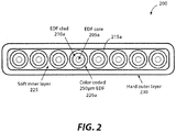
- FIG. 2 is a diagram showing a cross-section of another embodiment of ribbonized gain-doped fiber array.
- the gain-doped fiber array comprises a ribbon 200.
- the ribbon 200 of FIG. 2 comprises eight (8) color-coded gain-doped fibers 220a (e.g., 250- ⁇ m EDF) that are arranged linearly.
- each gain-doped fiber 220a comprises a gain-doped core 205a, a cladding 210a, and a coating layer 215a.
- the linear arrangement of gain-doped fibers is surrounded by a soft inner layer 225, which in turn is surrounded by a hard outer layer 230.
- FIGS. 3 through 6 show different embodiments of arrayed amplifier systems using ribbonized EDF.
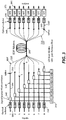
- FIG. 3 is a block diagram showing one embodiment of an arrayed amplifier using ribbonized EDF (ribbonized EDFA).
- the ribbonized EDFA system comprises an EDF ribbon 300 with EDFs 320 that are optically coupled to signal inputs 390 and signal outputs 395.
- each EDF 320 is optically coupled to a corresponding signal input 390 as well as a corresponding signal output 395.
- the signal from the signal input 390 propagates to a corresponding input optical isolator 335, and thereafter to a corresponding signal-pump combiner 340 (e.g., a wavelength division multiplexed (WDM) combiner).
- the signal-pump combiner 340 is optically coupled to a pump source, such as a laser diode 345 (e.g., 976 nm laser diode), which provides pump power for the signal.
- Each signal-pump combiner 340 is optically coupled to a corresponding single-mode fiber (SMF) 350 that is optically coupled to a corresponding EDF 320 with a core-matched splice 355, thereby permitting the signal to propagate from the signal-pump combiner 340 to its corresponding EDF 320.
- SMF single-mode fiber
- each individual EDF 320 can be separated by peeling a matrix off of the ribbon EDF 300 and then spliced to the signal-pump combiner.
- the amplified signal travels through an output optical isolator 370 (which is core-match spliced 360 to the EDF 320 by another SMF 365) and then through a gain-flattening filter (GFF) 375 to finally emerge at its corresponding signal output 395.
- GFF gain-flattening filter
- Other amplifier architectures are possible and are well known in the art. As shown in the embodiment of FIG. 3 , using a ribbonized EDF 300 permits a more compact amplifier array that can be manufactured at lower cost than other currently-available systems. Furthermore, it should be noted that the length of each individual EDF in the ribbon can be adjusted to achieve uniformity and consistency of gain shapes among the EDFAs. The flexibility in the lengths of the individual EDFs can also improve production yield of the arrayed EDFA.
- the flat gain spectra, and the uniformity and or consistency of the gain shapes in the arrayed EDFA are important for future DWDM transport systems.
- precise control of the doping composition and doping concentration are generally required, in addition to precise control of the fiber waveguide structure for each EDF in the ribbon.
- the gain spectrum of an EDFA depends on the EDF properties such as absorption, MFD, NA, cutoff wavelength, Al-ratio, etc., which are subject to manufacturing variability and the inversion level of the EDF, which will depend on the detailed configuration and operation conditions of the EDFA (such as the length of EDF, pump and signal power level etc).
- the Er-doped silica fibers are typically co-doped with Aluminium (Al), and Lanthanum (La) or Germanium (Ge) that are used to raise the index of refraction and modify the gain spectrum.
- Al concentration has the largest influence on the gain spectrum of EDF.
- the individual EDF made for EDF ribbon should have the same properties (such as absorption, emission, MFD, NA, cutoff wavelength, and background loss, etc.) in order to obtain good uniformity of gain shapes.
- Each EDFA in the 1x8 arrayed amplifier was pumped by 976nm LD in a co-propagation pumping scheme, and a 12 meter length of ribbon EDF was employed.
- the performance of the arrayed EDFA was evaluated by using 40 DFB diodes as the WDM (with 100GHz channel spacing) input signals which were combined together by an arrayed waveguide grating routers (AWR) and split into 8 as the input of signals into each individual EDFA in the arrayed amplifier.
- the composite input signals were adjusted by a variable optical attenuator (VOA) before input to each individual EDFA.
- VOA variable optical attenuator
- the input/output optical isolators, and input/output tap 99/1 taper couplers were used in the experiment, however, the GFF in output was not used.
- the achievable gain and NF of each individual EDFA were carefully measured and the gain deviations of each EDFA in the arrayed EDFA were also analyzed. The results are shown in FIGS. 7A and 7B .
- FIG. 7A shows the gain curves ranging from wavelength 1530.373nm to 1561.445nm from the 1x8 arrayed EDFA. It should be noted that the input powers are adjusted to be the same (2.6dBm total input power of 40 channels) for all 8 EDFAs, and the pump power of 415mW for each EDFA in the 1x8 arrayed EDFA were used in this measurement. The average gain of 19.3dB is obtained with average output power of 21.9dBm.
- FIG. 7B plots the average gain of the 8 EDFA and the gain deviation from the averaged gain curve. It can be see that the gain deviations ⁇ 0.8% can be obtained, exhibiting excellent gain shape uniformity among the EDFA within the array. The gain deviation can be further reduced by adjusting the length of individual EDF, and slightly adjusting the pump power.
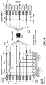
- FIG. 4 is a block diagram showing an embodiment of a ribbonized EDFA having shared pumps using optical splitters.
- each signal propagates through its respective input optical isolator 435, signal-pump combiner 440, SMF450, EDF 420 (coupled to the SMF 450 by a splice 455).
- the embodiment of FIG. 4 provides a pump sharing scheme in which pump power is provided through a combination of pump laser diodes 445, optical splitters 485, and variable optical attenuators (VOA) 480.
- VOA variable optical attenuators
- each EDF 420 is optically coupled to a corresponding SMF 465 by a core-matched splice 465.
- Each SMF 465 is optically coupled to a corresponding output optical isolator 470, which in turn is optically coupled to a corresponding GFF 475, which outputs the amplified signal through its corresponding signal output 495.
- the SMF 465 and GFF 475 are similar to the corresponding components in FIG. 3 , further discussion of the SMF 465 and GFF 475 is omitted here. It should, however, be noted that the embodiment of FIG. 4 , by employing ribbonized gain-doped fibers, also achieves similar efficiencies and advantages as those described with reference to FIG. 3 .
- FIG. 5 is a block diagram showing an embodiment of a ribbonized EDFA having both a co-pumping configuration and a counter-pumping configuration for high output power operation. Similar to the embodiment of FIG. 3 , the embodiment of FIG. 5 comprises signal inputs 590, input optical isolators 535, pump laser diodes 545, signal-pump combiners 540, SMF 550, EDF 520 in a ribbonized EDF 500, output optical isolators 570, GFF 575, and signal outputs 595. Insofar as these components have been described with reference to FIGS. 3 and 4 further discussion of these components is omitted here.
- the embodiment of FIG. 5 also includes a counter-pumping scheme, which comprises counter-pumping laser diodes 585, which are optically coupled to their corresponding SMFs 565 by another set of signal-pump combiners 580.
- a counter-pumping scheme which comprises counter-pumping laser diodes 585, which are optically coupled to their corresponding SMFs 565 by another set of signal-pump combiners 580.
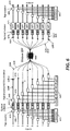
- FIG. 6 is a block diagram showing an embodiment of a ribbonized EDFA having power monitors. Similar to the embodiment of FIG. 3 , the embodiment of FIG.6 comprises signal inputs 690, input optical isolators 635, signal-pump combiners 640, pump laser diodes 645, SMF 640, EDF 620 in a ribbonized EDF 600, output optical isolators 670, GFF 675, and signal outputs 695. Since these components are discussed with reference to FIGS. 3 , 4 , and 5 further discussion of these components is omitted here. However, in addition to the components that are common from FIG. 3 , the embodiment of FIG. 6 includes input monitors 615 and output monitors 685.
- the input monitors are optically coupled to the signal inputs 690 with input tap couplers 610, thereby permitting input power measurements.
- the output monitors 685 are optically coupled to the signal outputs 695 with output tap couplers 680, thereby permitting output power measurements.
- the disclosed systems and methods comprise an arrayed optical fiber amplifier that uses a ribbonized fiber that permits reduction of amplifier module size and also reduction in the cost of manufacturing that are not readily achievable in other currently-available systems.
Landscapes
- Physics & Mathematics (AREA)
- Electromagnetism (AREA)
- Optics & Photonics (AREA)
- Engineering & Computer Science (AREA)
- Plasma & Fusion (AREA)
- General Physics & Mathematics (AREA)
- Lasers (AREA)
- Optical Communication System (AREA)
- Optical Couplings Of Light Guides (AREA)
- Optical Fibers, Optical Fiber Cores, And Optical Fiber Bundles (AREA)
Claims (8)
- Ein System, das folgende Merkmale aufweist:Signaleingänge (390-690);Signalausgänge (395-695); undein Band (100-600), das folgende Merkmale aufweist:ein Bandmatrixmaterial; underbiumdotierte Fasern (120, 220a), die in dem Bandmatrixmaterial angeordnet sind, wobei jede erbiumdotierte Faser (120, 220a) mit einem entsprechenden Signaleingang (390-690) optisch gekoppelt ist, wobei jede erbiumdotierte Faser (120, 220a) ferner mit einem entsprechenden Signalausgang (395-695) optisch gekoppelt ist, wobei jede erbiumdotierte Faser (120, 220a) folgende Merkmale aufweist:ein Aluminium(Al)-Co-Dotiermittel;RA1 innerhalb von etwa ±0,05 eines Ziel-RA1, wobei
 α1480nm die Absorption bei 1480nm ist; undαSpitze die Spitzenabsorption für die erbiumdotierte Faser (120, 220a) ist;αSpitze innerhalb von etwa ±3% einer Zielabsorption liegt;einen erbiumdotierten Kern;eine Umhüllung (110a, 210a), die den erbiumdotierten Kern umgibt; undeine Beschichtungsschicht (115a, 215a), die die Umhüllung (110a, 210a) umgibt.
 - Das System gemäß Anspruch 1:bei dem die Umhüllung (110a, 210a) einen Außendurchmesser von zwischen etwa 80µm und etwa 125µm aufweist; unddie Beschichtungsschicht (115a, 215a) einen Außendurchmesser von zwischen etwa 160µm und etwa 250µm aufweist.
- Das System gemäß Anspruch 1, das ferner folgende Merkmale aufweist:
Pumpquellen (345-645), die optisch mit den Signaleingängen (390-690) gekoppelt sind, wobei die Pumpquellen (345-645) dazu dienen, Pumpleistung durch WDM-Koppler (340-640) bereitzustellen. - Das System gemäß Anspruch 1, bei dem die erbiumdotierten Fasern (220a) farbcodiert sind.
- Das System gemäß Anspruch 1, bei dem die erbiumdotierten Fasern (220a) linear in dem Band angeordnet sind.
- Das System gemäß Anspruch 5, bei dem das Band acht farbcodierte erbiumdotierte Fasern (220a), EDF, aufweist, die linear angeordnet sind.
- Das System gemäß Anspruch 1, bei dem die erbiumdotierten Fasern (120, 220a), EDF, in einer im Wesentlichen dicht bepackten Konfiguration angeordnet sind.
- Das System gemäß Anspruch 1, das ferner folgende Merkmale aufweist:
Ausgangsmonitore (685), die mit dem Signalausgang (695) optisch gekoppelt sind.
Applications Claiming Priority (2)
| Application Number | Priority Date | Filing Date | Title |
|---|---|---|---|
| US201461978503P | 2014-04-11 | 2014-04-11 | |
| US14/633,521 US9379512B2 (en) | 2014-04-11 | 2015-02-27 | Arrayed optical fiber amplifier using ribbonized erbium-doped fiber |
Publications (3)
| Publication Number | Publication Date |
|---|---|
| EP2930799A2 EP2930799A2 (de) | 2015-10-14 |
| EP2930799A3 EP2930799A3 (de) | 2015-11-04 |
| EP2930799B1 true EP2930799B1 (de) | 2020-07-08 |
Family
ID=52823545
Family Applications (1)
| Application Number | Title | Priority Date | Filing Date |
|---|---|---|---|
| EP15163174.4A Active EP2930799B1 (de) | 2014-04-11 | 2015-04-10 | Angeordneter glasfaserverstärker unter verwendung von bandförmiger erbiumdotierter faser |
Country Status (3)
| Country | Link |
|---|---|
| US (1) | US9379512B2 (de) |
| EP (1) | EP2930799B1 (de) |
| JP (1) | JP6122057B2 (de) |
Families Citing this family (6)
| Publication number | Priority date | Publication date | Assignee | Title |
|---|---|---|---|---|
| JP2946323B2 (ja) | 1997-05-01 | 1999-09-06 | 株式会社島精機製作所 | 横編機の複合針 |
| WO2016112356A1 (en) | 2015-01-08 | 2016-07-14 | Acacia Communications, Inc. | Through transmission path on photonic circuits for optical alignment |
| WO2018119521A1 (en) * | 2016-12-27 | 2018-07-05 | Gc Photonics Inc. | Add drop structure |
| EP4032155A4 (de) * | 2019-09-19 | 2023-10-25 | Ofs Fitel Llc | Parallel-o-bandverstärker |
| CN112653940B (zh) * | 2020-11-27 | 2022-04-08 | 华为技术有限公司 | 光分配网络、光网络系统、分光器及分光器的端口识别方法 |
| US20240243539A1 (en) * | 2023-01-17 | 2024-07-18 | Ii-Vi Delaware, Inc. | Short fiber length multi-core fiber (mcf) erbium-doped fiber amplifiers (edfas) |
Family Cites Families (13)
| Publication number | Priority date | Publication date | Assignee | Title |
|---|---|---|---|---|
| US6229939B1 (en) * | 1999-06-03 | 2001-05-08 | Trw Inc. | High power fiber ribbon laser and amplifier |
| EP1180709B1 (de) * | 2000-08-09 | 2003-07-30 | Lucent Technologies Inc. | Bezüglich der effektiven Flächen ausbalanciertes optisches Kabel |
| US6512867B2 (en) * | 2000-11-29 | 2003-01-28 | Trw Inc. | Parallel side-pumping of dual-clad fiber array using fused, layered structure |
| US6570704B2 (en) * | 2001-03-14 | 2003-05-27 | Northrop Grumman Corporation | High average power chirped pulse fiber amplifier array |
| US6690867B2 (en) * | 2001-08-31 | 2004-02-10 | Corning Cable Systems Llc | Optical interconnect assemblies and methods therefor |
| US6792184B2 (en) * | 2002-05-31 | 2004-09-14 | Corning Cable Systems Llc | Optical fiber ribbons having a preferential separation sequence |
| US6748148B2 (en) * | 2002-05-31 | 2004-06-08 | Corning Cable Systems Llc | Optical fiber ribbons having a non-uniform thickness and/or preferential tear portions |
| US6957000B2 (en) * | 2002-10-31 | 2005-10-18 | Corning Cable Systems Llc | Peelable buffer layer having a preferential tear portion and methods of manufacturing the same |
| US7050688B2 (en) * | 2003-07-18 | 2006-05-23 | Corning Cable Systems Llc | Fiber optic articles, assemblies, and cables having optical waveguides |
| JP5616714B2 (ja) * | 2009-08-07 | 2014-10-29 | ノースロップ グラマン システムズ コーポレーション | 全ファイバ合成高出力コヒーレントビーム結合 |
| US8514485B2 (en) * | 2009-08-07 | 2013-08-20 | Northrop Grumman Systems Corporation | Passive all-fiber integrated high power coherent beam combination |
| US8725001B2 (en) * | 2010-03-10 | 2014-05-13 | Ofs Fitel, Llc | Multicore fiber transmission systems and methods |
| US8755112B2 (en) * | 2011-11-03 | 2014-06-17 | Gooch And Housego Plc | Optical fiber amplifier array |
-
2015
- 2015-02-27 US US14/633,521 patent/US9379512B2/en active Active
- 2015-04-10 JP JP2015080534A patent/JP6122057B2/ja active Active
- 2015-04-10 EP EP15163174.4A patent/EP2930799B1/de active Active
Non-Patent Citations (1)
| Title |
|---|
| None * |
Also Published As
| Publication number | Publication date |
|---|---|
| EP2930799A2 (de) | 2015-10-14 |
| EP2930799A3 (de) | 2015-11-04 |
| JP2016128898A (ja) | 2016-07-14 |
| US20150295382A1 (en) | 2015-10-15 |
| US9379512B2 (en) | 2016-06-28 |
| JP6122057B2 (ja) | 2017-04-26 |
Similar Documents
| Publication | Publication Date | Title |
|---|---|---|
| US11573365B2 (en) | Microstructured multicore optical fibre (MMOF), a device and the fabrication method of a device for independent addressing of the cores of microstructured multicore optical fibre | |
| EP2930799B1 (de) | Angeordneter glasfaserverstärker unter verwendung von bandförmiger erbiumdotierter faser | |
| Takenaga et al. | Reduction of crosstalk by trench-assisted multi-core fiber | |
| JP6794310B2 (ja) | マルチコアエルビウムドープファイバアンプ | |
| EP2721438B1 (de) | Verfahren und vorrichtungen zur verlustarmen kupplung an eine mehrkernfaser | |
| US6826335B1 (en) | Multi-fibre arrangements for high power fibre lasers and amplifiers | |
| US8755112B2 (en) | Optical fiber amplifier array | |
| Ono et al. | 12-core double-clad Er/Yb-doped fiber amplifier employing free-space coupling pump/signal combiner module | |
| Jung et al. | Multicore and multimode optical amplifiers for space division multiplexing | |
| Yung et al. | First demonstration of multimode amplifier for spatial division multiplexed transmission systems | |
| US20050207455A1 (en) | Method and apparatus for efficient coupling of pump light into fiber amplifiers | |
| Abedin et al. | State-of-the-art multicore fiber amplifiers for space division multiplexing | |
| WO2003014773A2 (en) | Dispersion managed discrete raman amplifiers | |
| Neugroschl et al. | High-efficiency (6+ 1) x1 combiner for high power fiber lasers and amplifiers | |
| Mélin et al. | Power efficient all-fiberized 12-core erbium/ytterbium doped optical amplifier | |
| Amma et al. | Ring-core multicore few-mode erbium-doped fiber amplifier | |
| Abedin et al. | Space division multiplexed multicore erbium-doped fiber amplifiers | |
| Ono et al. | Amplification technology for multi-core fiber transmission | |
| Simonneau et al. | High-power air-clad photonic crystal fiber cladding-pumped EDFA for WDM applications in the C-band | |
| US20220344888A1 (en) | Amplification fiber and optical amplifier | |
| JP2002158384A (ja) | 増幅用光ファイバ、光ファイバ増幅器、光送信器及び光通信システム | |
| Wada et al. | Coupled 2-LP 6-core EDFA with 125 μm cladding diameter | |
| Tsujikawa et al. | Optical fiber amplifier employing a bundle of reduced cladding erbium-doped fibers for multi-core fiber transmission | |
| Abedin et al. | Multicore erbium doped fiber amplifiers for space division multiplexed system | |
| Jung et al. | Multi-wavelength fiber laser using a single multicore erbium doped fiber |
Legal Events
| Date | Code | Title | Description |
|---|---|---|---|
| PUAL | Search report despatched |
Free format text: ORIGINAL CODE: 0009013 |
|
| PUAI | Public reference made under article 153(3) epc to a published international application that has entered the european phase |
Free format text: ORIGINAL CODE: 0009012 |
|
| AK | Designated contracting states |
Kind code of ref document: A2 Designated state(s): AL AT BE BG CH CY CZ DE DK EE ES FI FR GB GR HR HU IE IS IT LI LT LU LV MC MK MT NL NO PL PT RO RS SE SI SK SM TR |
|
| AX | Request for extension of the european patent |
Extension state: BA ME |
|
| AK | Designated contracting states |
Kind code of ref document: A3 Designated state(s): AL AT BE BG CH CY CZ DE DK EE ES FI FR GB GR HR HU IE IS IT LI LT LU LV MC MK MT NL NO PL PT RO RS SE SI SK SM TR |
|
| AX | Request for extension of the european patent |
Extension state: BA ME |
|
| RIC1 | Information provided on ipc code assigned before grant |
Ipc: H01S 3/16 20060101ALN20150928BHEP Ipc: H01S 3/0941 20060101ALN20150928BHEP Ipc: H01S 3/23 20060101ALI20150928BHEP Ipc: H01S 3/067 20060101AFI20150928BHEP Ipc: H01S 3/094 20060101ALN20150928BHEP Ipc: H01S 3/00 20060101ALN20150928BHEP |
|
| 17P | Request for examination filed |
Effective date: 20160309 |
|
| RBV | Designated contracting states (corrected) |
Designated state(s): AL AT BE BG CH CY CZ DE DK EE ES FI FR GB GR HR HU IE IS IT LI LT LU LV MC MK MT NL NO PL PT RO RS SE SI SK SM TR |
|
| STAA | Information on the status of an ep patent application or granted ep patent |
Free format text: STATUS: EXAMINATION IS IN PROGRESS |
|
| 17Q | First examination report despatched |
Effective date: 20170510 |
|
| GRAP | Despatch of communication of intention to grant a patent |
Free format text: ORIGINAL CODE: EPIDOSNIGR1 |
|
| STAA | Information on the status of an ep patent application or granted ep patent |
Free format text: STATUS: GRANT OF PATENT IS INTENDED |
|
| INTG | Intention to grant announced |
Effective date: 20191218 |
|
| RAP1 | Party data changed (applicant data changed or rights of an application transferred) |
Owner name: OFS FITEL, LLC (A DELAWARE LIMITED LIABILITY COMPA |
|
| GRAS | Grant fee paid |
Free format text: ORIGINAL CODE: EPIDOSNIGR3 |
|
| GRAA | (expected) grant |
Free format text: ORIGINAL CODE: 0009210 |
|
| STAA | Information on the status of an ep patent application or granted ep patent |
Free format text: STATUS: THE PATENT HAS BEEN GRANTED |
|
| AK | Designated contracting states |
Kind code of ref document: B1 Designated state(s): AL AT BE BG CH CY CZ DE DK EE ES FI FR GB GR HR HU IE IS IT LI LT LU LV MC MK MT NL NO PL PT RO RS SE SI SK SM TR |
|
| REG | Reference to a national code |
Ref country code: CH Ref legal event code: EP Ref country code: AT Ref legal event code: REF Ref document number: 1289478 Country of ref document: AT Kind code of ref document: T Effective date: 20200715 |
|
| REG | Reference to a national code |
Ref country code: DE Ref legal event code: R096 Ref document number: 602015055310 Country of ref document: DE |
|
| REG | Reference to a national code |
Ref country code: IE Ref legal event code: FG4D |
|
| REG | Reference to a national code |
Ref country code: LT Ref legal event code: MG4D |
|
| REG | Reference to a national code |
Ref country code: AT Ref legal event code: MK05 Ref document number: 1289478 Country of ref document: AT Kind code of ref document: T Effective date: 20200708 |
|
| REG | Reference to a national code |
Ref country code: NL Ref legal event code: MP Effective date: 20200708 |
|
| PG25 | Lapsed in a contracting state [announced via postgrant information from national office to epo] |
Ref country code: FI Free format text: LAPSE BECAUSE OF FAILURE TO SUBMIT A TRANSLATION OF THE DESCRIPTION OR TO PAY THE FEE WITHIN THE PRESCRIBED TIME-LIMIT Effective date: 20200708 Ref country code: HR Free format text: LAPSE BECAUSE OF FAILURE TO SUBMIT A TRANSLATION OF THE DESCRIPTION OR TO PAY THE FEE WITHIN THE PRESCRIBED TIME-LIMIT Effective date: 20200708 Ref country code: BG Free format text: LAPSE BECAUSE OF FAILURE TO SUBMIT A TRANSLATION OF THE DESCRIPTION OR TO PAY THE FEE WITHIN THE PRESCRIBED TIME-LIMIT Effective date: 20201008 Ref country code: LT Free format text: LAPSE BECAUSE OF FAILURE TO SUBMIT A TRANSLATION OF THE DESCRIPTION OR TO PAY THE FEE WITHIN THE PRESCRIBED TIME-LIMIT Effective date: 20200708 Ref country code: PT Free format text: LAPSE BECAUSE OF FAILURE TO SUBMIT A TRANSLATION OF THE DESCRIPTION OR TO PAY THE FEE WITHIN THE PRESCRIBED TIME-LIMIT Effective date: 20201109 Ref country code: ES Free format text: LAPSE BECAUSE OF FAILURE TO SUBMIT A TRANSLATION OF THE DESCRIPTION OR TO PAY THE FEE WITHIN THE PRESCRIBED TIME-LIMIT Effective date: 20200708 Ref country code: GR Free format text: LAPSE BECAUSE OF FAILURE TO SUBMIT A TRANSLATION OF THE DESCRIPTION OR TO PAY THE FEE WITHIN THE PRESCRIBED TIME-LIMIT Effective date: 20201009 Ref country code: NO Free format text: LAPSE BECAUSE OF FAILURE TO SUBMIT A TRANSLATION OF THE DESCRIPTION OR TO PAY THE FEE WITHIN THE PRESCRIBED TIME-LIMIT Effective date: 20201008 Ref country code: AT Free format text: LAPSE BECAUSE OF FAILURE TO SUBMIT A TRANSLATION OF THE DESCRIPTION OR TO PAY THE FEE WITHIN THE PRESCRIBED TIME-LIMIT Effective date: 20200708 Ref country code: SE Free format text: LAPSE BECAUSE OF FAILURE TO SUBMIT A TRANSLATION OF THE DESCRIPTION OR TO PAY THE FEE WITHIN THE PRESCRIBED TIME-LIMIT Effective date: 20200708 |
|
| PG25 | Lapsed in a contracting state [announced via postgrant information from national office to epo] |
Ref country code: PL Free format text: LAPSE BECAUSE OF FAILURE TO SUBMIT A TRANSLATION OF THE DESCRIPTION OR TO PAY THE FEE WITHIN THE PRESCRIBED TIME-LIMIT Effective date: 20200708 Ref country code: LV Free format text: LAPSE BECAUSE OF FAILURE TO SUBMIT A TRANSLATION OF THE DESCRIPTION OR TO PAY THE FEE WITHIN THE PRESCRIBED TIME-LIMIT Effective date: 20200708 Ref country code: RS Free format text: LAPSE BECAUSE OF FAILURE TO SUBMIT A TRANSLATION OF THE DESCRIPTION OR TO PAY THE FEE WITHIN THE PRESCRIBED TIME-LIMIT Effective date: 20200708 Ref country code: IS Free format text: LAPSE BECAUSE OF FAILURE TO SUBMIT A TRANSLATION OF THE DESCRIPTION OR TO PAY THE FEE WITHIN THE PRESCRIBED TIME-LIMIT Effective date: 20201108 |
|
| PG25 | Lapsed in a contracting state [announced via postgrant information from national office to epo] |
Ref country code: NL Free format text: LAPSE BECAUSE OF FAILURE TO SUBMIT A TRANSLATION OF THE DESCRIPTION OR TO PAY THE FEE WITHIN THE PRESCRIBED TIME-LIMIT Effective date: 20200708 |
|
| REG | Reference to a national code |
Ref country code: DE Ref legal event code: R097 Ref document number: 602015055310 Country of ref document: DE |
|
| PG25 | Lapsed in a contracting state [announced via postgrant information from national office to epo] |
Ref country code: IT Free format text: LAPSE BECAUSE OF FAILURE TO SUBMIT A TRANSLATION OF THE DESCRIPTION OR TO PAY THE FEE WITHIN THE PRESCRIBED TIME-LIMIT Effective date: 20200708 Ref country code: CZ Free format text: LAPSE BECAUSE OF FAILURE TO SUBMIT A TRANSLATION OF THE DESCRIPTION OR TO PAY THE FEE WITHIN THE PRESCRIBED TIME-LIMIT Effective date: 20200708 Ref country code: DK Free format text: LAPSE BECAUSE OF FAILURE TO SUBMIT A TRANSLATION OF THE DESCRIPTION OR TO PAY THE FEE WITHIN THE PRESCRIBED TIME-LIMIT Effective date: 20200708 Ref country code: EE Free format text: LAPSE BECAUSE OF FAILURE TO SUBMIT A TRANSLATION OF THE DESCRIPTION OR TO PAY THE FEE WITHIN THE PRESCRIBED TIME-LIMIT Effective date: 20200708 Ref country code: RO Free format text: LAPSE BECAUSE OF FAILURE TO SUBMIT A TRANSLATION OF THE DESCRIPTION OR TO PAY THE FEE WITHIN THE PRESCRIBED TIME-LIMIT Effective date: 20200708 Ref country code: SM Free format text: LAPSE BECAUSE OF FAILURE TO SUBMIT A TRANSLATION OF THE DESCRIPTION OR TO PAY THE FEE WITHIN THE PRESCRIBED TIME-LIMIT Effective date: 20200708 |
|
| PLBE | No opposition filed within time limit |
Free format text: ORIGINAL CODE: 0009261 |
|
| STAA | Information on the status of an ep patent application or granted ep patent |
Free format text: STATUS: NO OPPOSITION FILED WITHIN TIME LIMIT |
|
| PG25 | Lapsed in a contracting state [announced via postgrant information from national office to epo] |
Ref country code: AL Free format text: LAPSE BECAUSE OF FAILURE TO SUBMIT A TRANSLATION OF THE DESCRIPTION OR TO PAY THE FEE WITHIN THE PRESCRIBED TIME-LIMIT Effective date: 20200708 |
|
| 26N | No opposition filed |
Effective date: 20210409 |
|
| PG25 | Lapsed in a contracting state [announced via postgrant information from national office to epo] |
Ref country code: SK Free format text: LAPSE BECAUSE OF FAILURE TO SUBMIT A TRANSLATION OF THE DESCRIPTION OR TO PAY THE FEE WITHIN THE PRESCRIBED TIME-LIMIT Effective date: 20200708 |
|
| PG25 | Lapsed in a contracting state [announced via postgrant information from national office to epo] |
Ref country code: SI Free format text: LAPSE BECAUSE OF FAILURE TO SUBMIT A TRANSLATION OF THE DESCRIPTION OR TO PAY THE FEE WITHIN THE PRESCRIBED TIME-LIMIT Effective date: 20200708 |
|
| PG25 | Lapsed in a contracting state [announced via postgrant information from national office to epo] |
Ref country code: MC Free format text: LAPSE BECAUSE OF FAILURE TO SUBMIT A TRANSLATION OF THE DESCRIPTION OR TO PAY THE FEE WITHIN THE PRESCRIBED TIME-LIMIT Effective date: 20200708 |
|
| PG25 | Lapsed in a contracting state [announced via postgrant information from national office to epo] |
Ref country code: LU Free format text: LAPSE BECAUSE OF NON-PAYMENT OF DUE FEES Effective date: 20210410 |
|
| REG | Reference to a national code |
Ref country code: BE Ref legal event code: MM Effective date: 20210430 |
|
| PG25 | Lapsed in a contracting state [announced via postgrant information from national office to epo] |
Ref country code: LI Free format text: LAPSE BECAUSE OF NON-PAYMENT OF DUE FEES Effective date: 20210430 Ref country code: CH Free format text: LAPSE BECAUSE OF NON-PAYMENT OF DUE FEES Effective date: 20210430 |
|
| PG25 | Lapsed in a contracting state [announced via postgrant information from national office to epo] |
Ref country code: IE Free format text: LAPSE BECAUSE OF NON-PAYMENT OF DUE FEES Effective date: 20210410 |
|
| PG25 | Lapsed in a contracting state [announced via postgrant information from national office to epo] |
Ref country code: IS Free format text: LAPSE BECAUSE OF FAILURE TO SUBMIT A TRANSLATION OF THE DESCRIPTION OR TO PAY THE FEE WITHIN THE PRESCRIBED TIME-LIMIT Effective date: 20201108 |
|
| PG25 | Lapsed in a contracting state [announced via postgrant information from national office to epo] |
Ref country code: BE Free format text: LAPSE BECAUSE OF NON-PAYMENT OF DUE FEES Effective date: 20210430 |
|
| PG25 | Lapsed in a contracting state [announced via postgrant information from national office to epo] |
Ref country code: HU Free format text: LAPSE BECAUSE OF FAILURE TO SUBMIT A TRANSLATION OF THE DESCRIPTION OR TO PAY THE FEE WITHIN THE PRESCRIBED TIME-LIMIT; INVALID AB INITIO Effective date: 20150410 |
|
| P01 | Opt-out of the competence of the unified patent court (upc) registered |
Effective date: 20230411 |
|
| PG25 | Lapsed in a contracting state [announced via postgrant information from national office to epo] |
Ref country code: CY Free format text: LAPSE BECAUSE OF FAILURE TO SUBMIT A TRANSLATION OF THE DESCRIPTION OR TO PAY THE FEE WITHIN THE PRESCRIBED TIME-LIMIT Effective date: 20200708 |
|
| PG25 | Lapsed in a contracting state [announced via postgrant information from national office to epo] |
Ref country code: MK Free format text: LAPSE BECAUSE OF FAILURE TO SUBMIT A TRANSLATION OF THE DESCRIPTION OR TO PAY THE FEE WITHIN THE PRESCRIBED TIME-LIMIT Effective date: 20200708 |
|
| PG25 | Lapsed in a contracting state [announced via postgrant information from national office to epo] |
Ref country code: MT Free format text: LAPSE BECAUSE OF FAILURE TO SUBMIT A TRANSLATION OF THE DESCRIPTION OR TO PAY THE FEE WITHIN THE PRESCRIBED TIME-LIMIT Effective date: 20200708 |
|
| PGFP | Annual fee paid to national office [announced via postgrant information from national office to epo] |
Ref country code: DE Payment date: 20250529 Year of fee payment: 11 |
|
| PGFP | Annual fee paid to national office [announced via postgrant information from national office to epo] |
Ref country code: GB Payment date: 20250527 Year of fee payment: 11 |
|
| PGFP | Annual fee paid to national office [announced via postgrant information from national office to epo] |
Ref country code: FR Payment date: 20250526 Year of fee payment: 11 |
|
| PG25 | Lapsed in a contracting state [announced via postgrant information from national office to epo] |
Ref country code: TR Free format text: LAPSE BECAUSE OF FAILURE TO SUBMIT A TRANSLATION OF THE DESCRIPTION OR TO PAY THE FEE WITHIN THE PRESCRIBED TIME-LIMIT Effective date: 20200708 |