EP2930368A1 - Water pump - Google Patents
Water pump Download PDFInfo
- Publication number
- EP2930368A1 EP2930368A1 EP13860855.9A EP13860855A EP2930368A1 EP 2930368 A1 EP2930368 A1 EP 2930368A1 EP 13860855 A EP13860855 A EP 13860855A EP 2930368 A1 EP2930368 A1 EP 2930368A1
- Authority
- EP
- European Patent Office
- Prior art keywords
- storage space
- yoke
- liquid storage
- housing
- pump shaft
- Prior art date
- Legal status (The legal status is an assumption and is not a legal conclusion. Google has not performed a legal analysis and makes no representation as to the accuracy of the status listed.)
- Granted
Links
- XLYOFNOQVPJJNP-UHFFFAOYSA-N water Substances O XLYOFNOQVPJJNP-UHFFFAOYSA-N 0.000 title claims abstract description 31
- 239000007788 liquid Substances 0.000 claims abstract description 79
- 230000005540 biological transmission Effects 0.000 claims abstract description 12
- 239000000498 cooling water Substances 0.000 description 12
- 238000010276 construction Methods 0.000 description 9
- 239000000463 material Substances 0.000 description 7
- XEEYBQQBJWHFJM-UHFFFAOYSA-N Iron Chemical compound [Fe] XEEYBQQBJWHFJM-UHFFFAOYSA-N 0.000 description 6
- 238000001704 evaporation Methods 0.000 description 4
- 230000008020 evaporation Effects 0.000 description 4
- 230000004907 flux Effects 0.000 description 4
- 229910000990 Ni alloy Inorganic materials 0.000 description 3
- 239000000956 alloy Substances 0.000 description 3
- 229910052742 iron Inorganic materials 0.000 description 3
- 229910052751 metal Inorganic materials 0.000 description 2
- 239000002184 metal Substances 0.000 description 2
- 230000005855 radiation Effects 0.000 description 2
- 229910000838 Al alloy Inorganic materials 0.000 description 1
- 229910000639 Spring steel Inorganic materials 0.000 description 1
- 238000001514 detection method Methods 0.000 description 1
- 230000000694 effects Effects 0.000 description 1
- 238000010438 heat treatment Methods 0.000 description 1
- 239000007769 metal material Substances 0.000 description 1
- 239000011347 resin Substances 0.000 description 1
- 229920005989 resin Polymers 0.000 description 1
Images


Classifications
-
- F—MECHANICAL ENGINEERING; LIGHTING; HEATING; WEAPONS; BLASTING
- F04—POSITIVE - DISPLACEMENT MACHINES FOR LIQUIDS; PUMPS FOR LIQUIDS OR ELASTIC FLUIDS
- F04D—NON-POSITIVE-DISPLACEMENT PUMPS
- F04D13/00—Pumping installations or systems
- F04D13/02—Units comprising pumps and their driving means
- F04D13/021—Units comprising pumps and their driving means containing a coupling
-
- F—MECHANICAL ENGINEERING; LIGHTING; HEATING; WEAPONS; BLASTING
- F04—POSITIVE - DISPLACEMENT MACHINES FOR LIQUIDS; PUMPS FOR LIQUIDS OR ELASTIC FLUIDS
- F04D—NON-POSITIVE-DISPLACEMENT PUMPS
- F04D29/00—Details, component parts, or accessories
- F04D29/08—Sealings
- F04D29/10—Shaft sealings
- F04D29/106—Shaft sealings especially adapted for liquid pumps
-
- F—MECHANICAL ENGINEERING; LIGHTING; HEATING; WEAPONS; BLASTING
- F04—POSITIVE - DISPLACEMENT MACHINES FOR LIQUIDS; PUMPS FOR LIQUIDS OR ELASTIC FLUIDS
- F04D—NON-POSITIVE-DISPLACEMENT PUMPS
- F04D29/00—Details, component parts, or accessories
- F04D29/58—Cooling; Heating; Diminishing heat transfer
- F04D29/586—Cooling; Heating; Diminishing heat transfer specially adapted for liquid pumps
- F04D29/5893—Cooling; Heating; Diminishing heat transfer specially adapted for liquid pumps heat insulation or conduction
-
- F—MECHANICAL ENGINEERING; LIGHTING; HEATING; WEAPONS; BLASTING
- F05—INDEXING SCHEMES RELATING TO ENGINES OR PUMPS IN VARIOUS SUBCLASSES OF CLASSES F01-F04
- F05D—INDEXING SCHEME FOR ASPECTS RELATING TO NON-POSITIVE-DISPLACEMENT MACHINES OR ENGINES, GAS-TURBINES OR JET-PROPULSION PLANTS
- F05D2260/00—Function
- F05D2260/60—Fluid transfer
- F05D2260/602—Drainage
- F05D2260/6022—Drainage of leakage having past a seal
Definitions
- This invention relates to a water pump which includes a driving rotary body being drivingly rotated by a drive mechanism, a pump shaft rotating by a power transmission from the driving rotary body, a housing being inserted with the pump shaft, an impeller being fixed at one end side of the pump shaft, an electromagnetic clutch including a clutch portion being disposed at the other end side of the pump shaft, the clutch portion switching on and off the power transmission from the driving rotary body to the pump shaft, a mechanical seal being disposed at a position between the impeller and the clutch portion, the mechanical seal being mounted between the pump shaft and the housing, and a liquid storage space allowing to store a liquid leaking out from a side of the impeller to a side of the clutch portion via the mechanical seal.
- the electromagnetic clutch includes a yoke holding an electromagnetic coil and the liquid storage space is formed at the housing.
- a mechanical seal mounted between a pump shaft and a housing prevents a liquid from leaking out while allowing a seal member fixed at a side of the pump shaft and a seal member fixed at a side of the housing to relatively slide with each other. Thus, the liquid cannot be prevented from leaking out from a side of an impeller to a side of a clutch portion through a gap between the seal members.
- a water pump in which a liquid storage space which is able to store such a liquid is formed at the housing is disclosed.
- the housing is formed with an opening portion opening the liquid storage space to a side of a yoke and is provided with a cap which closes the opening portion.
- the cap is formed with a drain hole which is able to drain the liquid stored in the liquid storage space outside the housing.
- the water pump is configured such that the heat of the yoke heated by a heat generated by the energization to the electromagnetic coil is conducted to the housing via a fixing bracket fixing the yoke to the housing to heat the liquid storage space and the heat of the yoke vaporizes the liquid stored in the liquid storage space. Accordingly, the liquid and the vapor stored in the liquid storage space can be drained outside the housing via the drain hole formed at the cap.
- Patent Document 1 JP2010-242623A
- the present invention is made in light of the above-described circumstance and a purpose of the present invention is to provide a water pump that does not easily drain a liquid stored in a liquid storage space outside.
- a water pump includes a driving rotary body being drivingly rotated by a drive mechanism; a pump shaft rotating by a power transmission from the driving rotary body; a housing being inserted with the pump shaft; an impeller being fixed at one end side of the pump shaft; an electromagnetic clutch including a clutch portion being disposed at the other end side of the pump shaft, the clutch portion switching on and off the power transmission from the driving rotary body to the pump shaft; a mechanical seal being disposed at a position between the impeller and the clutch portion, the mechanical seal being mounted between the pump shaft and the housing; and a liquid storage space allowing to store a liquid leaking out from a side of the impeller to a side of the clutch portion via the mechanical seal; wherein the electromagnetic clutch includes a yoke holding an electromagnetic coil; the liquid storage space is formed at the housing; and the yoke is in contact with the housing.
- the yoke is in contact with the housing. Accordingly, the heat held at the yoke that is heated by a heat generated by the energization to the electromagnetic coil is effectively conducted to the housing without involving a member intervening between the yoke and the housing.
- the temperature of the liquid storage space is easily increased and because an amount of the liquid which can be vaporized at the liquid storage space is increased, the early increase of the liquid stored in the liquid storage space is prevented. Accordingly, because the liquid stored in the liquid storage space is not easily drained outside, the inconvenience of the misunderstanding that the trouble of the unexpected leak of the liquid from the pump occur may not occur easily.
- the housing is formed with an opening portion opening the liquid storage space to a side of the yoke; and the yoke is positioned so as to close the opening portion.
- a surface of the yoke facing the liquid storage space is provided with a projecting and recessed portion.
- a bottom portion of the liquid storage space is defined by a bottom surface which becomes lower as being closer to a side of the yoke.
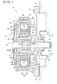
- Fig. 1 shows a water pump P for circulating cooling water, the water pump P mounted to an engine E (an example of a drive mechanism) for a vehicle according to this invention.
- the water pump P includes a drive pulley (an example of a driving rotary body) 1, a pump shaft 2, a pump housing 3, an impeller 4, an electromagnetic clutch 5, a mechanical seal 6 and a liquid storage space 7.
- the drive pulley 1 is drivingly rotated by the engine E.
- the pump shaft 2 rotates by a power transmission from the drive pulley 1.
- the pump housing 3 is inserted with the pump shaft 2.
- the impeller 4 is fixed at one end side of the pump shaft 2.
- the electromagnetic clutch 5 includes a clutch portion 5a being disposed at the other end side of the pump shaft 2, the clutch portion 5a switching on and off the power transmission from the drive pulley 1 to the pump shaft 2.
- the mechanical seal 6 is disposed at a position between the impeller 4 and the clutch portion 5a, and is mounted between the pump shaft 2 and the pump housing 3.
- the liquid storage space 7 allows to store a liquid leaking out from a side of the impeller 4 to a side of the clutch portion 5a via the mechanical seal 6.
- the pump housing 3 is integrally formed with a fixed flange portion 8 and a cylindrical shaft portion 9 which are made from a metal material, for example, aluminum alloy.
- the fixed flange portion 8 is fixed to an engine E.
- the cylindrical shaft portion 9 is formed in a cylindrical shape and is inserted with the pump shaft 2.
- the fixed flange portion 8 is formed with a circular shaft through hole 8a which is centered on a rotary axis X.
- the cylindrical shaft portion 9 is coaxial with the rotary axis X so as to be communicated with the shaft through hole 8a and is integrally formed with the fixed flange portion 8.
- the cylindrical shaft portion 9 is integrally provided with a large diameter cylindrical shaft portion 9a which is continuously provided with the fixed flange portion 8 and a small diameter cylindrical shaft portion 9b which is continuously provided with the large diameter cylindrical shaft portion 9a.
- the inner diameter of the large diameter cylindrical shaft portion 9a is formed to include the same diameter as the diameter of the shaft through hole 8a.
- the inner diameter of the small diameter cylindrical shaft portion 9b is formed to include the diameter smaller than the diameter of the shaft through hole 8a.
- the pump shaft 2 is inserted to be positioned inside the shaft through hole 8a and the cylindrical shaft portion 9 and is rotatably supported at an inner circumferential side of the small diameter cylindrical shaft portion 9b about the rotary axis X via a pump bearing 10.
- the mechanical seal 6 is mounted between an outer circumferential portion of the pump shaft 2 and an inner circumferential portion of the shaft through hole 8a.
- the drive pulley 1 is rotatably supported at an outer circumferential side of the small diameter cylindrical shaft portion 9b about the rotary axis X via a pulley bearing 11.
- the pump shaft 2 and the drive pulley 1 are relatively rotatably supported about the rotary axis X.
- the drive pulley 1 is made from a magnetic body material, for example, an iron material or a nickel alloy material, and is integrally provided with a cylindrical outer circumferential wall 1a, a cylindrical inner circumferential wall 1b and a side end wall 1c.
- the outer circumferential wall 1a is centered on the rotary axis X.
- the inner circumferential wall 1b is disposed at an inner side of the outer circumferential wall 1a and is centered on the rotary axis X.
- the side end wall 1c connects each end portion of the outer circumferential wall 1a and the inner circumferential wall 1b, the end portions which are disposed opposite to a side of the impeller 4.
- the side end wall 1c is disposed in an orientation orthogonal to the rotary axis X.
- the drive pulley 1 is formed with an annular space 12 which is surrounded by the outer circumferential wall 1a, the inner circumferential wall 1b and the side end wall 1c, and which opens to the side of the impeller 4.
- An electromagnetic solenoid 13 of the electromagnetic clutch 5 is positioned inside the annular space 12.
- a belt wound portion 14a wound with a drive belt 14 is formed at an outer circumferential surface of the outer circumferential wall 1a.
- the pulley bearing 11 is disposed such that an outer race is in contact with an inner circumferential surface of the inner circumferential wall 1b.
- a clutch surface 16 attracting an armature (a clutch plate) 15 is formed at an outer surface side of the side end wall 1c, the outer surface side which is disposed in a direction opposite to a side of the electromagnetic solenoid 13.
- the side end wall 1c is formed with plural through holes 16a which is long in a circumferential direction and which penetrates the clutch surface 16.
- the through holes 16a are disposed apart from one another at an interval in the circumferential direction.
- the drive belt 14 is hung and wound around an output pulley provided at the crankshaft of the engine E and the drive pulley 1 and drivingly rotates the drive pulley 1 continuously when starting up the engine E.
- the switching of the power transmission operated by the electromagnetic clutch 5 is controlled on the basis of detection results of a temperature sensor (not shown in the drawings) detecting, for example, the water temperature of cooling water.
- the electromagnetic clutch 5 is maintained off state (disconnected state) to facilitate the warm up.
- the electromagnetic clutch 5 is switched to an on state (connected state) to circulate cooling water by the drive rotation of the impeller 4.
- the electromagnetic clutch 5 is configured with the electromagnetic solenoid 13 which is housed in the annular space 12 of the drive pulley 1, and a clutch unit 17 which integrally rotates with the pump shaft 2.
- a magnetic circuit which applies the magnetic flux transmitted from the electromagnetic solenoid 13 on the armature 15 is formed on the drive pulley 1.
- the electromagnetic solenoid 13 includes a solenoid portion 18 which generates the magnetic flux by energization, and a yoke 19 which is made from a magnetic body material, for example, an iron material or a nickel alloy material to transmit the magnetic flux transmitted from the solenoid portion 18 to the drive pulley 1.
- a solenoid portion 18 which generates the magnetic flux by energization
- a yoke 19 which is made from a magnetic body material, for example, an iron material or a nickel alloy material to transmit the magnetic flux transmitted from the solenoid portion 18 to the drive pulley 1.
- the yoke 19 is integrally formed with an inner cylindrical portion 19a, an outer cylindrical portion 19b and an annular connection plate portion 19c to be formed in an annular shape including the C-shape cross section.
- the inner cylindrical portion 19a and the outer cylindrical portion 19b are formed in a cylindrical shape and are coaxially disposed with the rotary axis X.
- the connection plate portion 19c connects each end portion of the inner cylindrical portion 19a and the outer cylindrical portion 19b, the end portions disposed at the side of the impeller 4.
- the inner cylindrical portion 19a is disposed close to the inner circumferential wall 1b, and the outer cylindrical portion 19b is disposed close to the outer circumferential wall 1a, and the connection plate portion 19c is disposed in the orientation orthogonal to the rotary axis X.
- the electromagnetic clutch 5 includes the yoke 19 which holds the electromagnetic coil 18b inside the yoke 19.
- the clutch unit 17 includes a bush 20 which is fitted onto an end portion of the pump shaft 2, and plural spring plates 21 which bias the annular armature 15 to be away from the side end wall 1c of the drive pulley 1 while supporting the armature 15 to the bush 20.
- the armature 15 is made from a magnetic body, for example, an iron material or a nickel alloy material.
- a plate material which can be elastically deformed as spring steel is used for the spring plates 21, and one end is connected to a flange portion of the bush 20 and the other end is connected to the armature 15.
- the electromagnetic solenoid 13 When the electromagnetic solenoid 13 is energized, a part of the magnetic flux formed at the magnetic circuit which is configured by the yoke 19 and the drive pulley 1 leaks outward via the through hole 16a of the side end wall 1c and affects the armature 15.
- the armature 15 is attracted to the clutch surface 16 and the electromagnetic clutch 5 is switched to be in the on state. Accordingly, the clutch unit 17 configures the clutch portion 5a which switches on and off the power transmission from the drive pulley 1 to the pump shaft 2.
- the fixed flange portion 8 configuring the pump housing 3 is integrally provided with a cylindrical wall portion 22 which is coaxial with the rotary axis X, and the cylindrical wall portion 22 is fixed to the yoke 19.
- the liquid storage space 7 is formed annularly and is disposed between the cylindrical wall portion 22 and the large diameter cylindrical shaft portion 9a.
- An opening portion 23 opening the liquid storage space 7 to the side of the yoke 19 is formed between respective end portions of the cylindrical wall portion 22 and the large diameter cylindrical shaft portion 9a.
- the connection plate portion 19c is directly in contact with the cylindrical wall portion 22 and is positioned so as to close an outer circumferential side portion of the opening portion 23 of the liquid storage space 7.
- an inflow hole 24 which flows, for example, cooling water leaking out from the mechanical seal 6 to a side of the pump bearing 10 to the liquid storage space 7 by its own weight is formed through in a cylindrical diameter direction.
- each of drain holes 26 which can drain, for example, cooling water vaporized in the liquid storage space 7 outside is formed through at an upper portion and a side portion of the cylindrical wall portion 22.
- the drain hole 26 may be single or plural, and can drain water vapor of cooling water (liquid) W stored in the liquid storage space 7 to an upper side of the pump housing 3.
- the heat held at the yoke 19 that is heated by the heat generated by the energization to the electromagnetic coil 18b can be effectively conducted to the liquid storage space 7 via the connection plate portion 19c and the cylindrical wall portion 22, the evaporation of cooling water stored in the liquid storage space 7 can be facilitated.
- a plate-shaped cap 25 which is made of resin or metal and which closes the entire circumference and the entire area of the opening portion 23 of the liquid storage space 7 is mounted so as be in contact with a plate surface of the connection plate portion 19c.
- the yoke 19 can be exposed to the liquid storage space 7 by including the cap 25 which closes only a gap between the yoke 19 and the cylindrical shaft portion 9 or by not being mounted with the cap 25.
- Fig. 3 shows another embodiment of a water pump P according to this invention.
- a lower side portion of the liquid storage space 7 is defined by a bottom surface 27 which becomes lower as being closer to the side of the yoke 19. That is, the inclination bottom surface 27 which becomes lower as being closer to the side of the yoke 19 is formed at a portion of a lower end side, in a vertical direction, of the inner circumferential surface of the cylindrical wall portion 22.
- cooling water flowing into the liquid storage space 7 is flown to be close to the side of the yoke 19 by its own weight and the evaporation of cooling water can be facilitated.
- Other construction is identical to the first embodiment.
- a surface of the yoke 19 which exposes to and faces the liquid storage space 7 can be provided with a projecting and recessed portion by being formed with, for example, a projecting and recessed surface or a rough surface at the surface of the yoke 19, or, by being projectingly fixed with, for example, a metal fin, which are not shown in the drawings.
- the heat radiation area from the yoke 19 to the liquid storage space 7 may be further increased to enhance the evaporation effect of cooling water.
- a yoke and a housing which are made from a magnetic body material may be integrally formed.
- the water pump of this invention can be applied to various types of water pumps which include electromagnetic clutches.
Landscapes
- Engineering & Computer Science (AREA)
- Mechanical Engineering (AREA)
- General Engineering & Computer Science (AREA)
- Physics & Mathematics (AREA)
- Thermal Sciences (AREA)
- Structures Of Non-Positive Displacement Pumps (AREA)
Abstract
Description
- This invention relates to a water pump which includes a driving rotary body being drivingly rotated by a drive mechanism, a pump shaft rotating by a power transmission from the driving rotary body, a housing being inserted with the pump shaft, an impeller being fixed at one end side of the pump shaft, an electromagnetic clutch including a clutch portion being disposed at the other end side of the pump shaft, the clutch portion switching on and off the power transmission from the driving rotary body to the pump shaft, a mechanical seal being disposed at a position between the impeller and the clutch portion, the mechanical seal being mounted between the pump shaft and the housing, and a liquid storage space allowing to store a liquid leaking out from a side of the impeller to a side of the clutch portion via the mechanical seal. This invention relates to the water pump in which the electromagnetic clutch includes a yoke holding an electromagnetic coil and the liquid storage space is formed at the housing.
- A mechanical seal mounted between a pump shaft and a housing prevents a liquid from leaking out while allowing a seal member fixed at a side of the pump shaft and a seal member fixed at a side of the housing to relatively slide with each other. Thus, the liquid cannot be prevented from leaking out from a side of an impeller to a side of a clutch portion through a gap between the seal members.
- According to
Patent Document 1, in order not to drain a liquid leaking out via a mechanical seal outside a housing, a water pump in which a liquid storage space which is able to store such a liquid is formed at the housing is disclosed. The housing is formed with an opening portion opening the liquid storage space to a side of a yoke and is provided with a cap which closes the opening portion. The cap is formed with a drain hole which is able to drain the liquid stored in the liquid storage space outside the housing. Further, the water pump is configured such that the heat of the yoke heated by a heat generated by the energization to the electromagnetic coil is conducted to the housing via a fixing bracket fixing the yoke to the housing to heat the liquid storage space and the heat of the yoke vaporizes the liquid stored in the liquid storage space. Accordingly, the liquid and the vapor stored in the liquid storage space can be drained outside the housing via the drain hole formed at the cap. - Patent Document 1:
JP2010-242623A - According to the water pump described in
Patent Document 1, because the heat of the yoke that is heated by generation of heat of the electromagnetic coil is conducted to the housing via the fixing bracket, the heat of the yoke is easily radiated outside the fixing bracket before heating the liquid storage space sufficiently. Thus, even if the heat of the yoke is conducted to the housing, the liquid storage space cannot be easily and sufficiently heated. As a result, because an amount of the liquid which can be vaporized at the liquid storage space is reduced, the liquid stored in the liquid storage space is increased early and is easily drained outside from the drain hole. In a case where the liquid stored in the liquid storage space is drained outside from the drain hole, there is an inconvenience of misunderstanding, arising from a trace of the drain, that a trouble of unexpected leak of the liquid from the pump occurs. The present invention is made in light of the above-described circumstance and a purpose of the present invention is to provide a water pump that does not easily drain a liquid stored in a liquid storage space outside. - According to the first characterized construction of this invention, a water pump includes a driving rotary body being drivingly rotated by a drive mechanism; a pump shaft rotating by a power transmission from the driving rotary body; a housing being inserted with the pump shaft; an impeller being fixed at one end side of the pump shaft; an electromagnetic clutch including a clutch portion being disposed at the other end side of the pump shaft, the clutch portion switching on and off the power transmission from the driving rotary body to the pump shaft; a mechanical seal being disposed at a position between the impeller and the clutch portion, the mechanical seal being mounted between the pump shaft and the housing; and a liquid storage space allowing to store a liquid leaking out from a side of the impeller to a side of the clutch portion via the mechanical seal; wherein the electromagnetic clutch includes a yoke holding an electromagnetic coil; the liquid storage space is formed at the housing; and the yoke is in contact with the housing.
- According to the water pump of this construction, the yoke is in contact with the housing. Accordingly, the heat held at the yoke that is heated by a heat generated by the energization to the electromagnetic coil is effectively conducted to the housing without involving a member intervening between the yoke and the housing. Thus, according to the water pump of this configuration, because the temperature of the liquid storage space is easily increased and because an amount of the liquid which can be vaporized at the liquid storage space is increased, the early increase of the liquid stored in the liquid storage space is prevented. Accordingly, because the liquid stored in the liquid storage space is not easily drained outside, the inconvenience of the misunderstanding that the trouble of the unexpected leak of the liquid from the pump occur may not occur easily.
- According to the second characterized construction of this invention, the housing is formed with an opening portion opening the liquid storage space to a side of the yoke; and the yoke is positioned so as to close the opening portion.
- According to this construction, because the heat held at the yoke is radiated to the liquid storage space without involving the housing, the increase of the temperature at the liquid storage space can be facilitated.
- According to the third characterized construction of this invention, a surface of the yoke facing the liquid storage space is provided with a projecting and recessed portion.
- According to this construction, a heat radiation area from the yoke to the liquid storage space can be increased.
- According to the fourth characterized construction of this invention, a bottom portion of the liquid storage space is defined by a bottom surface which becomes lower as being closer to a side of the yoke.
- According to this construction, because the liquid flowing into the liquid storage space is flown to the side of the yoke by its own weight, the evaporation of the liquid can be facilitated.
-
- [
Fig. 1 ] Longitudinal cross sectional view showing a water pump according to this invention [Fig. 2 ] Cross sectional view taken along the line II-II inFig. 1 - [
Fig. 3 ] Longitudinal cross sectional view showing a water pump of a second embodiment according to this invention - Embodiments of this invention will be explained hereunder on the basis of the drawings.
-
Fig. 1 shows a water pump P for circulating cooling water, the water pump P mounted to an engine E (an example of a drive mechanism) for a vehicle according to this invention. - The water pump P includes a drive pulley (an example of a driving rotary body) 1, a
pump shaft 2, apump housing 3, animpeller 4, anelectromagnetic clutch 5, amechanical seal 6 and aliquid storage space 7. Thedrive pulley 1 is drivingly rotated by the engine E. Thepump shaft 2 rotates by a power transmission from thedrive pulley 1. Thepump housing 3 is inserted with thepump shaft 2. Theimpeller 4 is fixed at one end side of thepump shaft 2. Theelectromagnetic clutch 5 includes aclutch portion 5a being disposed at the other end side of thepump shaft 2, theclutch portion 5a switching on and off the power transmission from thedrive pulley 1 to thepump shaft 2. Themechanical seal 6 is disposed at a position between theimpeller 4 and theclutch portion 5a, and is mounted between thepump shaft 2 and thepump housing 3. Theliquid storage space 7 allows to store a liquid leaking out from a side of theimpeller 4 to a side of theclutch portion 5a via themechanical seal 6. - The
pump housing 3 is integrally formed with a fixedflange portion 8 and acylindrical shaft portion 9 which are made from a metal material, for example, aluminum alloy. The fixedflange portion 8 is fixed to an engine E. Thecylindrical shaft portion 9 is formed in a cylindrical shape and is inserted with thepump shaft 2. Thefixed flange portion 8 is formed with a circular shaft throughhole 8a which is centered on a rotary axis X. Thecylindrical shaft portion 9 is coaxial with the rotary axis X so as to be communicated with the shaft throughhole 8a and is integrally formed with the fixedflange portion 8. - The
cylindrical shaft portion 9 is integrally provided with a large diametercylindrical shaft portion 9a which is continuously provided with the fixedflange portion 8 and a small diametercylindrical shaft portion 9b which is continuously provided with the large diametercylindrical shaft portion 9a. The inner diameter of the large diametercylindrical shaft portion 9a is formed to include the same diameter as the diameter of the shaft throughhole 8a. The inner diameter of the small diametercylindrical shaft portion 9b is formed to include the diameter smaller than the diameter of the shaft throughhole 8a. - The
pump shaft 2 is inserted to be positioned inside the shaft throughhole 8a and thecylindrical shaft portion 9 and is rotatably supported at an inner circumferential side of the small diametercylindrical shaft portion 9b about the rotary axis X via a pump bearing 10. Themechanical seal 6 is mounted between an outer circumferential portion of thepump shaft 2 and an inner circumferential portion of the shaft throughhole 8a. - The
drive pulley 1 is rotatably supported at an outer circumferential side of the small diametercylindrical shaft portion 9b about the rotary axis X via a pulley bearing 11. Thus, thepump shaft 2 and thedrive pulley 1 are relatively rotatably supported about the rotary axis X. - The
drive pulley 1 is made from a magnetic body material, for example, an iron material or a nickel alloy material, and is integrally provided with a cylindrical outercircumferential wall 1a, a cylindrical innercircumferential wall 1b and aside end wall 1c. The outercircumferential wall 1a is centered on the rotary axis X. The innercircumferential wall 1b is disposed at an inner side of the outercircumferential wall 1a and is centered on the rotary axis X. Theside end wall 1c connects each end portion of the outercircumferential wall 1a and the innercircumferential wall 1b, the end portions which are disposed opposite to a side of theimpeller 4. Theside end wall 1c is disposed in an orientation orthogonal to the rotary axis X. - The
drive pulley 1 is formed with anannular space 12 which is surrounded by the outercircumferential wall 1a, the innercircumferential wall 1b and theside end wall 1c, and which opens to the side of theimpeller 4. Anelectromagnetic solenoid 13 of theelectromagnetic clutch 5 is positioned inside theannular space 12. - A
belt wound portion 14a wound with adrive belt 14 is formed at an outer circumferential surface of the outercircumferential wall 1a. The pulley bearing 11 is disposed such that an outer race is in contact with an inner circumferential surface of the innercircumferential wall 1b. Aclutch surface 16 attracting an armature (a clutch plate) 15 is formed at an outer surface side of theside end wall 1c, the outer surface side which is disposed in a direction opposite to a side of theelectromagnetic solenoid 13. Theside end wall 1c is formed with plural throughholes 16a which is long in a circumferential direction and which penetrates theclutch surface 16. The throughholes 16a are disposed apart from one another at an interval in the circumferential direction. - The
drive belt 14 is hung and wound around an output pulley provided at the crankshaft of the engine E and thedrive pulley 1 and drivingly rotates thedrive pulley 1 continuously when starting up the engine E. The switching of the power transmission operated by theelectromagnetic clutch 5 is controlled on the basis of detection results of a temperature sensor (not shown in the drawings) detecting, for example, the water temperature of cooling water. - For example, in a case where the water temperature of cooling water is low, for example, immediately after the startup of the engine E (when the engine E is not sufficiently warmed), the
electromagnetic clutch 5 is maintained off state (disconnected state) to facilitate the warm up. In a case where the water temperature of cooling water exceeds a predetermined value, theelectromagnetic clutch 5 is switched to an on state (connected state) to circulate cooling water by the drive rotation of theimpeller 4. - The
electromagnetic clutch 5 is configured with theelectromagnetic solenoid 13 which is housed in theannular space 12 of thedrive pulley 1, and aclutch unit 17 which integrally rotates with thepump shaft 2. A magnetic circuit which applies the magnetic flux transmitted from theelectromagnetic solenoid 13 on thearmature 15 is formed on thedrive pulley 1. - The
electromagnetic solenoid 13 includes asolenoid portion 18 which generates the magnetic flux by energization, and ayoke 19 which is made from a magnetic body material, for example, an iron material or a nickel alloy material to transmit the magnetic flux transmitted from thesolenoid portion 18 to thedrive pulley 1. - The
yoke 19 is integrally formed with an innercylindrical portion 19a, an outercylindrical portion 19b and an annularconnection plate portion 19c to be formed in an annular shape including the C-shape cross section. The innercylindrical portion 19a and the outercylindrical portion 19b are formed in a cylindrical shape and are coaxially disposed with the rotary axis X. Theconnection plate portion 19c connects each end portion of the innercylindrical portion 19a and the outercylindrical portion 19b, the end portions disposed at the side of theimpeller 4. The innercylindrical portion 19a is disposed close to the innercircumferential wall 1b, and the outercylindrical portion 19b is disposed close to the outercircumferential wall 1a, and theconnection plate portion 19c is disposed in the orientation orthogonal to the rotary axis X. - At the
solenoid portion 18, abobbin 18a is wound with anelectromagnetic coil 18b and is fitted inside theyoke 19. Thus, theelectromagnetic clutch 5 includes theyoke 19 which holds theelectromagnetic coil 18b inside theyoke 19. - The
clutch unit 17 includes abush 20 which is fitted onto an end portion of thepump shaft 2, andplural spring plates 21 which bias theannular armature 15 to be away from theside end wall 1c of thedrive pulley 1 while supporting thearmature 15 to thebush 20. - The
armature 15 is made from a magnetic body, for example, an iron material or a nickel alloy material. A plate material which can be elastically deformed as spring steel is used for thespring plates 21, and one end is connected to a flange portion of thebush 20 and the other end is connected to thearmature 15. - When the
electromagnetic solenoid 13 is not energized, thearmature 15 is away from theclutch surface 16 of theside end wall 1c by the biasing force of thespring plates 21 and theelectromagnetic clutch 5 has been switched in the off state. - When the
electromagnetic solenoid 13 is energized, a part of the magnetic flux formed at the magnetic circuit which is configured by theyoke 19 and thedrive pulley 1 leaks outward via the throughhole 16a of theside end wall 1c and affects thearmature 15. Thearmature 15 is attracted to theclutch surface 16 and theelectromagnetic clutch 5 is switched to be in the on state. Accordingly, theclutch unit 17 configures theclutch portion 5a which switches on and off the power transmission from thedrive pulley 1 to thepump shaft 2. - At a side of the fixed
flange portion 8 which is close to theyoke 19, the fixedflange portion 8 configuring thepump housing 3 is integrally provided with acylindrical wall portion 22 which is coaxial with the rotary axis X, and thecylindrical wall portion 22 is fixed to theyoke 19. - The
liquid storage space 7 is formed annularly and is disposed between thecylindrical wall portion 22 and the large diametercylindrical shaft portion 9a. An openingportion 23 opening theliquid storage space 7 to the side of theyoke 19 is formed between respective end portions of thecylindrical wall portion 22 and the large diametercylindrical shaft portion 9a. At theyoke 19, theconnection plate portion 19c is directly in contact with thecylindrical wall portion 22 and is positioned so as to close an outer circumferential side portion of the openingportion 23 of theliquid storage space 7. - At the large diameter
cylindrical shaft portion 9a, aninflow hole 24 which flows, for example, cooling water leaking out from themechanical seal 6 to a side of thepump bearing 10 to theliquid storage space 7 by its own weight is formed through in a cylindrical diameter direction. As shown inFig. 2 , each of drain holes 26 which can drain, for example, cooling water vaporized in theliquid storage space 7 outside is formed through at an upper portion and a side portion of thecylindrical wall portion 22. Thedrain hole 26 may be single or plural, and can drain water vapor of cooling water (liquid) W stored in theliquid storage space 7 to an upper side of thepump housing 3. - Accordingly, because the heat held at the
yoke 19 that is heated by the heat generated by the energization to theelectromagnetic coil 18b can be effectively conducted to theliquid storage space 7 via theconnection plate portion 19c and thecylindrical wall portion 22, the evaporation of cooling water stored in theliquid storage space 7 can be facilitated. - A plate-shaped
cap 25 which is made of resin or metal and which closes the entire circumference and the entire area of the openingportion 23 of theliquid storage space 7 is mounted so as be in contact with a plate surface of theconnection plate portion 19c. Alternatively, theyoke 19 can be exposed to theliquid storage space 7 by including thecap 25 which closes only a gap between theyoke 19 and thecylindrical shaft portion 9 or by not being mounted with thecap 25. -
Fig. 3 shows another embodiment of a water pump P according to this invention. According to this embodiment, a lower side portion of theliquid storage space 7 is defined by abottom surface 27 which becomes lower as being closer to the side of theyoke 19. That is, theinclination bottom surface 27 which becomes lower as being closer to the side of theyoke 19 is formed at a portion of a lower end side, in a vertical direction, of the inner circumferential surface of thecylindrical wall portion 22. - By including the
bottom surface 27 which is inclined as described above, cooling water flowing into theliquid storage space 7 is flown to be close to the side of theyoke 19 by its own weight and the evaporation of cooling water can be facilitated. Other construction is identical to the first embodiment. - A surface of the
yoke 19 which exposes to and faces theliquid storage space 7 can be provided with a projecting and recessed portion by being formed with, for example, a projecting and recessed surface or a rough surface at the surface of theyoke 19, or, by being projectingly fixed with, for example, a metal fin, which are not shown in the drawings. By including the projecting and recessed portion, the heat radiation area from theyoke 19 to theliquid storage space 7 may be further increased to enhance the evaporation effect of cooling water. - 1. According to a water pump of this invention, a yoke and a housing which are made from a magnetic body material may be integrally formed.
- The water pump of this invention can be applied to various types of water pumps which include electromagnetic clutches.
-
- 1
- driving rotary body
- 2
- pump shaft
- 3
- housing
- 4
- impeller
- 5
- electromagnetic clutch
- 5a
- clutch portion
- 6
- mechanical seal
- 7
- liquid storage space
- 18b
- electromagnetic coil
- 19
- yoke
- 23
- opening portion
- 27
- bottom surface
- E
- drive mechanism
Claims (6)
- A water pump, comprising:a driving rotary body being drivingly rotated by a drive mechanism;a pump shaft rotating by a power transmission from the driving rotary body;a housing being inserted with the pump shaft;an impeller being fixed at one end side of the pump shaft;an electromagnetic clutch including a clutch portion being disposed at the other end side of the pump shaft, the clutch portion switching on and off the power transmission from the driving rotary body to the pump shaft;a mechanical seal being disposed at a position between the impeller and the clutch portion, the mechanical seal being mounted between the pump shaft and the housing; anda liquid storage space allowing to store a liquid leaking out from a side of the impeller to a side of the clutch portion via the mechanical seal; whereinthe electromagnetic clutch includes a yoke holding an electromagnetic coil;the liquid storage space is formed at the housing; andthe yoke is in contact with the housing.
- The water pump according to claim 1, wherein
the housing is formed with an opening portion opening the liquid storage space to a side of the yoke; and
the yoke is positioned so as to close the opening portion. - The water pump according to claim 2, wherein a surface of the yoke facing the
liquid storage space is provided with a projecting and recessed portion. - The water pump according to claim 1, wherein a bottom portion of the liquid
storage space is defined by a bottom surface which becomes lower as being closer to a side of the yoke. - The water pump according to claim 2, wherein a bottom portion of the liquid
storage space is defined by a bottom surface which becomes lower as being closer to the side of the yoke. - The water pump according to claim 3, wherein a bottom portion of the liquid
storage space is defined by a bottom surface which becomes lower as being closer to the side of the yoke.
Applications Claiming Priority (2)
| Application Number | Priority Date | Filing Date | Title |
|---|---|---|---|
| JP2012265496A JP6107092B2 (en) | 2012-12-04 | 2012-12-04 | Water pump |
| PCT/JP2013/081348 WO2014087845A1 (en) | 2012-12-04 | 2013-11-21 | Water pump |
Publications (3)
| Publication Number | Publication Date |
|---|---|
| EP2930368A1 true EP2930368A1 (en) | 2015-10-14 |
| EP2930368A4 EP2930368A4 (en) | 2015-12-23 |
| EP2930368B1 EP2930368B1 (en) | 2019-04-03 |
Family
ID=50883269
Family Applications (1)
| Application Number | Title | Priority Date | Filing Date |
|---|---|---|---|
| EP13860855.9A Not-in-force EP2930368B1 (en) | 2012-12-04 | 2013-11-21 | Water pump |
Country Status (3)
| Country | Link |
|---|---|
| EP (1) | EP2930368B1 (en) |
| JP (1) | JP6107092B2 (en) |
| WO (1) | WO2014087845A1 (en) |
Cited By (1)
| Publication number | Priority date | Publication date | Assignee | Title |
|---|---|---|---|---|
| US10393140B2 (en) * | 2015-10-20 | 2019-08-27 | Tbk Co., Ltd. | Fluid pump |
Families Citing this family (3)
| Publication number | Priority date | Publication date | Assignee | Title |
|---|---|---|---|---|
| CN108104937A (en) * | 2017-11-30 | 2018-06-01 | 无锡惠山泵业有限公司 | A kind of clutch variable water pump |
| KR102188166B1 (en) * | 2019-09-30 | 2020-12-07 | 현대자동차주식회사 | Water pump-cooling fan assembly and method of controlling the same |
| CN114837792A (en) | 2021-03-10 | 2022-08-02 | 美普盛(上海)汽车零部件有限公司 | Electric coolant pump with expansion compensation sealing element |
Family Cites Families (13)
| Publication number | Priority date | Publication date | Assignee | Title |
|---|---|---|---|---|
| JPS6052289B2 (en) * | 1978-02-20 | 1985-11-18 | トヨタ自動車株式会社 | Cooling fan drive device |
| JP2862695B2 (en) * | 1991-02-14 | 1999-03-03 | 富士通株式会社 | Circuit module mounting structure |
| JPH0635870U (en) * | 1992-10-20 | 1994-05-13 | 大阪瓦斯株式会社 | Gas engine heat pump |
| JP3383888B2 (en) * | 1994-05-17 | 2003-03-10 | 愛知機械工業株式会社 | Water pump structure |
| JPH10165297A (en) * | 1996-12-11 | 1998-06-23 | Showa Alum Corp | Electromagnetic cooking utensil and method of manufacturing the same |
| JP2001044347A (en) * | 1999-07-28 | 2001-02-16 | Furukawa Electric Co Ltd:The | Heat sink and manufacturing method thereof |
| JP4013713B2 (en) * | 2002-09-18 | 2007-11-28 | アイシン精機株式会社 | Water pump |
| JP2005251861A (en) * | 2004-03-02 | 2005-09-15 | Denso Corp | Electronic control device for vehicle and method for assembling the same |
| JP5011968B2 (en) * | 2006-11-10 | 2012-08-29 | アイシン精機株式会社 | Water pump |
| JP4597198B2 (en) * | 2007-02-23 | 2010-12-15 | シャープ株式会社 | Wall materials and buildings |
| BRPI0823230A2 (en) * | 2008-11-18 | 2015-06-16 | Melling Do Brasil Componentes Automotivos Ltda | Water pump and pumping mechanism |
| JP2010242623A (en) * | 2009-04-07 | 2010-10-28 | Hitachi Automotive Systems Ltd | Water pump |
| JP2011075140A (en) * | 2009-09-29 | 2011-04-14 | Noritz Corp | Air conditioning device including drainage discharge suppressing function, and range hood including the same |
-
2012
- 2012-12-04 JP JP2012265496A patent/JP6107092B2/en not_active Expired - Fee Related
-
2013
- 2013-11-21 WO PCT/JP2013/081348 patent/WO2014087845A1/en not_active Ceased
- 2013-11-21 EP EP13860855.9A patent/EP2930368B1/en not_active Not-in-force
Cited By (1)
| Publication number | Priority date | Publication date | Assignee | Title |
|---|---|---|---|---|
| US10393140B2 (en) * | 2015-10-20 | 2019-08-27 | Tbk Co., Ltd. | Fluid pump |
Also Published As
| Publication number | Publication date |
|---|---|
| WO2014087845A1 (en) | 2014-06-12 |
| EP2930368A4 (en) | 2015-12-23 |
| JP2014109261A (en) | 2014-06-12 |
| JP6107092B2 (en) | 2017-04-05 |
| EP2930368B1 (en) | 2019-04-03 |
Similar Documents
| Publication | Publication Date | Title |
|---|---|---|
| EP2930368B1 (en) | Water pump | |
| US11085449B2 (en) | Pump assembly for recirculating a cooling fluid of a heat engine | |
| US11476736B2 (en) | Electric motor | |
| US9451869B2 (en) | Washing machine with a direct drive system | |
| US5076216A (en) | Coolant pump with clutch | |
| US9709105B2 (en) | Clutch mechanism | |
| EP2613072A1 (en) | Fluid control valve | |
| US7757830B2 (en) | Dual armature device for transmitting the movement to fans for cooling the engine of motor vehicles | |
| JP6678002B2 (en) | Fluid pump | |
| EP1640582A1 (en) | Device for transmitting the movement to fans for cooling engines | |
| CN104747620A (en) | Electromagnetic clutch | |
| EP2351918B1 (en) | Mechanical combustion engine coolant pump | |
| WO2014204129A1 (en) | Electronic actuator for fan clutch | |
| JP2014062511A (en) | Water pump | |
| JP2005117752A (en) | Stepping motor | |
| JP6131582B2 (en) | Electromagnetic clutch | |
| JP6442880B2 (en) | Control valve | |
| JP2010242623A (en) | Water pump | |
| EP2599976A1 (en) | Device for transmitting the movement to fans for cooling engines with stoppage of the fan in an idle condition thereof | |
| JP2013189886A (en) | Water pump | |
| JP6968157B2 (en) | Water pump | |
| JP2004150300A (en) | Water pump | |
| EP3714140B1 (en) | Device for driving at three speeds fans for cooling the coolant in motor vehicles | |
| JP2009257354A (en) | Driving force distribution device |
Legal Events
| Date | Code | Title | Description |
|---|---|---|---|
| PUAI | Public reference made under article 153(3) epc to a published international application that has entered the european phase |
Free format text: ORIGINAL CODE: 0009012 |
|
| 17P | Request for examination filed |
Effective date: 20150511 |
|
| AK | Designated contracting states |
Kind code of ref document: A1 Designated state(s): AL AT BE BG CH CY CZ DE DK EE ES FI FR GB GR HR HU IE IS IT LI LT LU LV MC MK MT NL NO PL PT RO RS SE SI SK SM TR |
|
| AX | Request for extension of the european patent |
Extension state: BA ME |
|
| RA4 | Supplementary search report drawn up and despatched (corrected) |
Effective date: 20151119 |
|
| RIC1 | Information provided on ipc code assigned before grant |
Ipc: F04D 29/58 20060101ALI20151113BHEP Ipc: F04D 29/10 20060101ALI20151113BHEP Ipc: F04D 13/02 20060101AFI20151113BHEP |
|
| DAX | Request for extension of the european patent (deleted) | ||
| GRAP | Despatch of communication of intention to grant a patent |
Free format text: ORIGINAL CODE: EPIDOSNIGR1 |
|
| STAA | Information on the status of an ep patent application or granted ep patent |
Free format text: STATUS: GRANT OF PATENT IS INTENDED |
|
| INTG | Intention to grant announced |
Effective date: 20190104 |
|
| GRAS | Grant fee paid |
Free format text: ORIGINAL CODE: EPIDOSNIGR3 |
|
| GRAA | (expected) grant |
Free format text: ORIGINAL CODE: 0009210 |
|
| STAA | Information on the status of an ep patent application or granted ep patent |
Free format text: STATUS: THE PATENT HAS BEEN GRANTED |
|
| AK | Designated contracting states |
Kind code of ref document: B1 Designated state(s): AL AT BE BG CH CY CZ DE DK EE ES FI FR GB GR HR HU IE IS IT LI LT LU LV MC MK MT NL NO PL PT RO RS SE SI SK SM TR |
|
| REG | Reference to a national code |
Ref country code: GB Ref legal event code: FG4D |
|
| REG | Reference to a national code |
Ref country code: CH Ref legal event code: EP Ref country code: AT Ref legal event code: REF Ref document number: 1116079 Country of ref document: AT Kind code of ref document: T Effective date: 20190415 |
|
| REG | Reference to a national code |
Ref country code: DE Ref legal event code: R096 Ref document number: 602013053465 Country of ref document: DE |
|
| REG | Reference to a national code |
Ref country code: IE Ref legal event code: FG4D |
|
| REG | Reference to a national code |
Ref country code: NL Ref legal event code: MP Effective date: 20190403 |
|
| REG | Reference to a national code |
Ref country code: LT Ref legal event code: MG4D |
|
| REG | Reference to a national code |
Ref country code: AT Ref legal event code: MK05 Ref document number: 1116079 Country of ref document: AT Kind code of ref document: T Effective date: 20190403 |
|
| PG25 | Lapsed in a contracting state [announced via postgrant information from national office to epo] |
Ref country code: NL Free format text: LAPSE BECAUSE OF FAILURE TO SUBMIT A TRANSLATION OF THE DESCRIPTION OR TO PAY THE FEE WITHIN THE PRESCRIBED TIME-LIMIT Effective date: 20190403 |
|
| PG25 | Lapsed in a contracting state [announced via postgrant information from national office to epo] |
Ref country code: AL Free format text: LAPSE BECAUSE OF FAILURE TO SUBMIT A TRANSLATION OF THE DESCRIPTION OR TO PAY THE FEE WITHIN THE PRESCRIBED TIME-LIMIT Effective date: 20190403 Ref country code: PT Free format text: LAPSE BECAUSE OF FAILURE TO SUBMIT A TRANSLATION OF THE DESCRIPTION OR TO PAY THE FEE WITHIN THE PRESCRIBED TIME-LIMIT Effective date: 20190803 Ref country code: SE Free format text: LAPSE BECAUSE OF FAILURE TO SUBMIT A TRANSLATION OF THE DESCRIPTION OR TO PAY THE FEE WITHIN THE PRESCRIBED TIME-LIMIT Effective date: 20190403 Ref country code: FI Free format text: LAPSE BECAUSE OF FAILURE TO SUBMIT A TRANSLATION OF THE DESCRIPTION OR TO PAY THE FEE WITHIN THE PRESCRIBED TIME-LIMIT Effective date: 20190403 Ref country code: NO Free format text: LAPSE BECAUSE OF FAILURE TO SUBMIT A TRANSLATION OF THE DESCRIPTION OR TO PAY THE FEE WITHIN THE PRESCRIBED TIME-LIMIT Effective date: 20190703 Ref country code: HR Free format text: LAPSE BECAUSE OF FAILURE TO SUBMIT A TRANSLATION OF THE DESCRIPTION OR TO PAY THE FEE WITHIN THE PRESCRIBED TIME-LIMIT Effective date: 20190403 Ref country code: LT Free format text: LAPSE BECAUSE OF FAILURE TO SUBMIT A TRANSLATION OF THE DESCRIPTION OR TO PAY THE FEE WITHIN THE PRESCRIBED TIME-LIMIT Effective date: 20190403 Ref country code: ES Free format text: LAPSE BECAUSE OF FAILURE TO SUBMIT A TRANSLATION OF THE DESCRIPTION OR TO PAY THE FEE WITHIN THE PRESCRIBED TIME-LIMIT Effective date: 20190403 Ref country code: CZ Free format text: LAPSE BECAUSE OF FAILURE TO SUBMIT A TRANSLATION OF THE DESCRIPTION OR TO PAY THE FEE WITHIN THE PRESCRIBED TIME-LIMIT Effective date: 20190403 |
|
| PG25 | Lapsed in a contracting state [announced via postgrant information from national office to epo] |
Ref country code: RS Free format text: LAPSE BECAUSE OF FAILURE TO SUBMIT A TRANSLATION OF THE DESCRIPTION OR TO PAY THE FEE WITHIN THE PRESCRIBED TIME-LIMIT Effective date: 20190403 Ref country code: PL Free format text: LAPSE BECAUSE OF FAILURE TO SUBMIT A TRANSLATION OF THE DESCRIPTION OR TO PAY THE FEE WITHIN THE PRESCRIBED TIME-LIMIT Effective date: 20190403 Ref country code: BG Free format text: LAPSE BECAUSE OF FAILURE TO SUBMIT A TRANSLATION OF THE DESCRIPTION OR TO PAY THE FEE WITHIN THE PRESCRIBED TIME-LIMIT Effective date: 20190703 Ref country code: LV Free format text: LAPSE BECAUSE OF FAILURE TO SUBMIT A TRANSLATION OF THE DESCRIPTION OR TO PAY THE FEE WITHIN THE PRESCRIBED TIME-LIMIT Effective date: 20190403 Ref country code: GR Free format text: LAPSE BECAUSE OF FAILURE TO SUBMIT A TRANSLATION OF THE DESCRIPTION OR TO PAY THE FEE WITHIN THE PRESCRIBED TIME-LIMIT Effective date: 20190704 |
|
| PG25 | Lapsed in a contracting state [announced via postgrant information from national office to epo] |
Ref country code: IS Free format text: LAPSE BECAUSE OF FAILURE TO SUBMIT A TRANSLATION OF THE DESCRIPTION OR TO PAY THE FEE WITHIN THE PRESCRIBED TIME-LIMIT Effective date: 20190803 Ref country code: AT Free format text: LAPSE BECAUSE OF FAILURE TO SUBMIT A TRANSLATION OF THE DESCRIPTION OR TO PAY THE FEE WITHIN THE PRESCRIBED TIME-LIMIT Effective date: 20190403 |
|
| REG | Reference to a national code |
Ref country code: DE Ref legal event code: R097 Ref document number: 602013053465 Country of ref document: DE |
|
| PG25 | Lapsed in a contracting state [announced via postgrant information from national office to epo] |
Ref country code: DK Free format text: LAPSE BECAUSE OF FAILURE TO SUBMIT A TRANSLATION OF THE DESCRIPTION OR TO PAY THE FEE WITHIN THE PRESCRIBED TIME-LIMIT Effective date: 20190403 Ref country code: EE Free format text: LAPSE BECAUSE OF FAILURE TO SUBMIT A TRANSLATION OF THE DESCRIPTION OR TO PAY THE FEE WITHIN THE PRESCRIBED TIME-LIMIT Effective date: 20190403 Ref country code: RO Free format text: LAPSE BECAUSE OF FAILURE TO SUBMIT A TRANSLATION OF THE DESCRIPTION OR TO PAY THE FEE WITHIN THE PRESCRIBED TIME-LIMIT Effective date: 20190403 Ref country code: SK Free format text: LAPSE BECAUSE OF FAILURE TO SUBMIT A TRANSLATION OF THE DESCRIPTION OR TO PAY THE FEE WITHIN THE PRESCRIBED TIME-LIMIT Effective date: 20190403 |
|
| PLBE | No opposition filed within time limit |
Free format text: ORIGINAL CODE: 0009261 |
|
| STAA | Information on the status of an ep patent application or granted ep patent |
Free format text: STATUS: NO OPPOSITION FILED WITHIN TIME LIMIT |
|
| PG25 | Lapsed in a contracting state [announced via postgrant information from national office to epo] |
Ref country code: SM Free format text: LAPSE BECAUSE OF FAILURE TO SUBMIT A TRANSLATION OF THE DESCRIPTION OR TO PAY THE FEE WITHIN THE PRESCRIBED TIME-LIMIT Effective date: 20190403 Ref country code: IT Free format text: LAPSE BECAUSE OF FAILURE TO SUBMIT A TRANSLATION OF THE DESCRIPTION OR TO PAY THE FEE WITHIN THE PRESCRIBED TIME-LIMIT Effective date: 20190403 |
|
| 26N | No opposition filed |
Effective date: 20200106 |
|
| PG25 | Lapsed in a contracting state [announced via postgrant information from national office to epo] |
Ref country code: TR Free format text: LAPSE BECAUSE OF FAILURE TO SUBMIT A TRANSLATION OF THE DESCRIPTION OR TO PAY THE FEE WITHIN THE PRESCRIBED TIME-LIMIT Effective date: 20190403 |
|
| PG25 | Lapsed in a contracting state [announced via postgrant information from national office to epo] |
Ref country code: SI Free format text: LAPSE BECAUSE OF FAILURE TO SUBMIT A TRANSLATION OF THE DESCRIPTION OR TO PAY THE FEE WITHIN THE PRESCRIBED TIME-LIMIT Effective date: 20190403 |
|
| REG | Reference to a national code |
Ref country code: CH Ref legal event code: PL |
|
| PG25 | Lapsed in a contracting state [announced via postgrant information from national office to epo] |
Ref country code: LU Free format text: LAPSE BECAUSE OF NON-PAYMENT OF DUE FEES Effective date: 20191121 Ref country code: MC Free format text: LAPSE BECAUSE OF FAILURE TO SUBMIT A TRANSLATION OF THE DESCRIPTION OR TO PAY THE FEE WITHIN THE PRESCRIBED TIME-LIMIT Effective date: 20190403 Ref country code: LI Free format text: LAPSE BECAUSE OF NON-PAYMENT OF DUE FEES Effective date: 20191130 Ref country code: CH Free format text: LAPSE BECAUSE OF NON-PAYMENT OF DUE FEES Effective date: 20191130 |
|
| REG | Reference to a national code |
Ref country code: BE Ref legal event code: MM Effective date: 20191130 |
|
| GBPC | Gb: european patent ceased through non-payment of renewal fee |
Effective date: 20191121 |
|
| PG25 | Lapsed in a contracting state [announced via postgrant information from national office to epo] |
Ref country code: IE Free format text: LAPSE BECAUSE OF NON-PAYMENT OF DUE FEES Effective date: 20191121 Ref country code: GB Free format text: LAPSE BECAUSE OF NON-PAYMENT OF DUE FEES Effective date: 20191121 |
|
| PG25 | Lapsed in a contracting state [announced via postgrant information from national office to epo] |
Ref country code: BE Free format text: LAPSE BECAUSE OF NON-PAYMENT OF DUE FEES Effective date: 20191130 |
|
| PGFP | Annual fee paid to national office [announced via postgrant information from national office to epo] |
Ref country code: DE Payment date: 20201110 Year of fee payment: 8 Ref country code: FR Payment date: 20201013 Year of fee payment: 8 |
|
| PG25 | Lapsed in a contracting state [announced via postgrant information from national office to epo] |
Ref country code: CY Free format text: LAPSE BECAUSE OF FAILURE TO SUBMIT A TRANSLATION OF THE DESCRIPTION OR TO PAY THE FEE WITHIN THE PRESCRIBED TIME-LIMIT Effective date: 20190403 |
|
| PG25 | Lapsed in a contracting state [announced via postgrant information from national office to epo] |
Ref country code: MT Free format text: LAPSE BECAUSE OF FAILURE TO SUBMIT A TRANSLATION OF THE DESCRIPTION OR TO PAY THE FEE WITHIN THE PRESCRIBED TIME-LIMIT Effective date: 20190403 Ref country code: HU Free format text: LAPSE BECAUSE OF FAILURE TO SUBMIT A TRANSLATION OF THE DESCRIPTION OR TO PAY THE FEE WITHIN THE PRESCRIBED TIME-LIMIT; INVALID AB INITIO Effective date: 20131121 |
|
| REG | Reference to a national code |
Ref country code: DE Ref legal event code: R119 Ref document number: 602013053465 Country of ref document: DE |
|
| PG25 | Lapsed in a contracting state [announced via postgrant information from national office to epo] |
Ref country code: MK Free format text: LAPSE BECAUSE OF FAILURE TO SUBMIT A TRANSLATION OF THE DESCRIPTION OR TO PAY THE FEE WITHIN THE PRESCRIBED TIME-LIMIT Effective date: 20190403 |
|
| PG25 | Lapsed in a contracting state [announced via postgrant information from national office to epo] |
Ref country code: DE Free format text: LAPSE BECAUSE OF NON-PAYMENT OF DUE FEES Effective date: 20220601 |
|
| PG25 | Lapsed in a contracting state [announced via postgrant information from national office to epo] |
Ref country code: FR Free format text: LAPSE BECAUSE OF NON-PAYMENT OF DUE FEES Effective date: 20211130 |