EP2930112A1 - A table arrangement - Google Patents
A table arrangement Download PDFInfo
- Publication number
- EP2930112A1 EP2930112A1 EP15275112.9A EP15275112A EP2930112A1 EP 2930112 A1 EP2930112 A1 EP 2930112A1 EP 15275112 A EP15275112 A EP 15275112A EP 2930112 A1 EP2930112 A1 EP 2930112A1
- Authority
- EP
- European Patent Office
- Prior art keywords
- arrangement
- shaft
- spool
- mounting structure
- lowered
- Prior art date
- Legal status (The legal status is an assumption and is not a legal conclusion. Google has not performed a legal analysis and makes no representation as to the accuracy of the status listed.)
- Granted
Links
Images


Classifications
-
- B—PERFORMING OPERATIONS; TRANSPORTING
- B64—AIRCRAFT; AVIATION; COSMONAUTICS
- B64D—EQUIPMENT FOR FITTING IN OR TO AIRCRAFT; FLIGHT SUITS; PARACHUTES; ARRANGEMENT OR MOUNTING OF POWER PLANTS OR PROPULSION TRANSMISSIONS IN AIRCRAFT
- B64D11/00—Passenger or crew accommodation; Flight-deck installations not otherwise provided for
- B64D11/06—Arrangements of seats, or adaptations or details specially adapted for aircraft seats
- B64D11/0638—Arrangements of seats, or adaptations or details specially adapted for aircraft seats with foldable tables, trays or cup holders
-
- A—HUMAN NECESSITIES
- A47—FURNITURE; DOMESTIC ARTICLES OR APPLIANCES; COFFEE MILLS; SPICE MILLS; SUCTION CLEANERS IN GENERAL
- A47B—TABLES; DESKS; OFFICE FURNITURE; CABINETS; DRAWERS; GENERAL DETAILS OF FURNITURE
- A47B3/00—Folding or stowable tables
- A47B3/002—Folding or stowable tables with foldable underframe
-
- A—HUMAN NECESSITIES
- A47—FURNITURE; DOMESTIC ARTICLES OR APPLIANCES; COFFEE MILLS; SPICE MILLS; SUCTION CLEANERS IN GENERAL
- A47B—TABLES; DESKS; OFFICE FURNITURE; CABINETS; DRAWERS; GENERAL DETAILS OF FURNITURE
- A47B3/00—Folding or stowable tables
- A47B3/14—Foldable table and seat units
-
- B—PERFORMING OPERATIONS; TRANSPORTING
- B60—VEHICLES IN GENERAL
- B60N—SEATS SPECIALLY ADAPTED FOR VEHICLES; VEHICLE PASSENGER ACCOMMODATION NOT OTHERWISE PROVIDED FOR
- B60N3/00—Arrangements or adaptations of other passenger fittings, not otherwise provided for
- B60N3/001—Arrangements or adaptations of other passenger fittings, not otherwise provided for of tables or trays
- B60N3/002—Arrangements or adaptations of other passenger fittings, not otherwise provided for of tables or trays of trays
- B60N3/004—Arrangements or adaptations of other passenger fittings, not otherwise provided for of tables or trays of trays of foldable trays mounted on the back-rest
Definitions
- the present invention concerns a table arrangement for use in an aircraft seat module. More particularly, but not exclusively, this invention concerns the table arrangement comprising a table mounting structure, a table moveably mounted to the table mounting structure such that it can move between a lowered position and a raised position, a compensation arrangement connected between the table and table mounting structure for reducing the force required to lift the table from the lowered position to the raised position, and a damper arrangement for reducing the speed of the table as it moves from the raised position to the lowered position.
- the invention also concerns an aircraft seat module and a method of deploying or stowing a table arrangement.
- a prior art table arrangement comprises a table and table mounting structure where a constant force sprung band wound around a spool (compensation arrangement) is used to assist in the raising of the table from a lowered position to a raised position.
- the spool is rotatably mounted to the table mounting structure and a free end of the sprung band is attached to the table.
- the compensation arrangement acts to help pull the table up to the raised position.
- the damping arrangement comprises a rack and pinion mechanism, with the rack mounted to the table mounting structure.
- the rack is a vertical bar with a mesh on one side of it.
- a cog (with corresponding teeth to the mesh) is rotatably mounted on the table such that the teeth interlock with the mesh of the rack.
- the cog on the table rotates as the table moves up and down in relation to the rack.
- the cog's rotation on its axis is damped by a rotary damper.
- the rack and pinion mechanism can often be heavier and more complicated than is ideal. This adds weight to the table arrangement (especially undesirable in relation to an aircraft seat module) and can make maintenance, manufacture and repair more complicated and time-consuming, and therefore, more expensive.
- the present invention seeks to mitigate the above-mentioned problems. Alternatively or additionally, the present invention seeks to provide an improved table arrangement.
- the present invention provides, according to a first aspect, a table arrangement for use in an aircraft seat module, the table arrangement comprising a table mounting structure, a table moveably mounted to the table mounting structure such that it can move between a lowered position and a raised position, a compensation arrangement connected between the table and table mounting structure for reducing the force required to lift the table from the lowered position to the raised position, and a damper arrangement for reducing the speed of the table as it moves from the raised position to the lowered position, wherein the compensation arrangement is mounted on a shaft, such that as the table is lowered, the shaft rotates about its longitudinal axis and wherein the damping arrangement is arranged to act on the shaft to reduce the speed of its rotation about its longitudinal axis.
- damping arrangement is much smaller as there is no need for a separate rack and pinion mechanism, for example.
- the damping is provided by damping an existing shaft (associated with the compensation arrangement).
- the damping arrangement acts on the shaft associated with the compensation arrangement. It does not simply provide damping elsewhere, for example on a separate arrangement between the table and table mounting structure (that inevitably may also damp the rotation of the shaft).
- the damping arrangement acts directly on the shaft.
- the damping arrangement is uni-directional. In other words, it only reduces the speed of the table as it moves from the raised position to the lowered position - it does not reduce the speed of the table as it moves from the lowered position to the raised position.
- the compensation arrangement comprises a spool mounted on the shaft and an elongate member for winding onto and unwinding from the spool during lowering and raising of the table, wherein the compensation arrangement is biased such that the elongate member is urged to wind onto or unwind from the spool.
- lowering and raising of the table causes winding onto and unwinding from the spool by the elongate member, and rotation of the spool.
- the elongate member winds onto the spool during raising of the table. In this case, the elongate member unwinds from the spool during lowering of the table.
- the spool is fixedly mounted on the shaft such that rotation of the spool causes rotation of the shaft about its longitudinal axis.
- the elongate member is biased to wind onto the spool. If the elongate member winds onto the spool during raising of the table, this biases the table to the raised position.
- the elongate member is urged to wind onto the spool by a spring returning towards its default position, and wherein the spring is tensioned away from its default position when the elongate member is unwound from the spool.
- the elongate member comprises the spring. Even more preferably, the elongate member is the spring.
- the shaft is caused to rotate by the compensation arrangement.
- the shaft is mounted to the table and a free end of the elongate member is attached to the table mounting structure.
- the damping arrangement comprises a rotary damper mounted on the shaft, coaxially with the compensation arrangement. More preferably, the damping arrangement and the compensation arrangement are close to each other (proximate). Even more preferably, the damping arrangement and the compensation arrangement are at the same end of the table (or table mounting structure) as each other. Even more preferably, the damping arrangement and the compensation arrangement are directly adjacent to each other.
- the direction of table movement between the lowered and raised positions is approximately within the plane of the table.
- the table does not move substantially out of its plane between the lowered and raised positions. This means that the table movement between these positions requires only a small space.
- the table could be vertical and move vertically from the lowered position to the raised position, thus only needing a small space in order to provide for this movement.
- the table mounting structure comprises a housing which stows the table in the lowered position.
- the table is slidably mounted to the table mounting structure with a cam follower and cam track arrangement.
- the raised position is a deployed position and the lowered position is a stowed position.
- the raised position is a partly deployed position.
- the table is further moved from the raised position to a fully deployed position.
- the table will fall under its own weight (under gravity) from the raised position to the lowered position and wherein the table needs to be assisted by a user to move it from the fully deployed position to the raised position.
- the table may be held by gravity in the fully deployed (for example, horizontal) position, by use of a stop. The table then needs to be rotated towards the raised position (for example, substantially vertical) so that it reaches past a "tipping point" and falls under gravity to the lowered position.
- an aircraft seat module comprising a seat, and a table arrangement as described above, and wherein the table mounting structure is mounted to the aircraft seat module.
- the table is arranged such that it moves substantially vertically between the lowered and raised positions.
- an aircraft comprising a table arrangement or aircraft seat module as described above.
- a method of deploying and stowing a table arrangement of an aircraft seat module comprising a table mounting structure and a table moveably mounted to the table mounting structure such that it can move between a lowered stowed position and a raised at least partly deployed position, a compensation arrangement connected between the table and table mounting structure and mounted on a shaft, and a damping arrangement
- the method comprising the steps of raising the table, with the assistance of the compensation arrangement, from the lowered position to the raised position, and lowering the table, with the assistance of gravity, thus causing the shaft to rotate and the damper arrangement to act on the shaft to reduce the speed of its rotation about its longitudinal axis, thereby reducing the speed of the table as it moves from the raised position to the lowered position.
- Figures 1a and 1b show views of a table arrangement 100 according to a first embodiment of the invention, in a presented configuration.
- the table arrangement 100 comprises a door 110 with a rectangular front face 112, a left side panel 113 and a right side panel 114.
- a handle 111 is located towards the top of the front face 112.
- the door 110 is pivotally mounted to a table housing 130.
- the door is pivotally mounted by hinges 117 on the two side panels 113, 114 towards the front and bottom of the side panels.
- the door 110 also has a cam track (not shown) on the internally facing surface of the side panel 114.
- the door 110 has been opened by pulling on the handle 111 to pivot the door 110 on the hinges 117 by approximately 20 to 30 degrees.
- a table 120 is presented in the housing 130 at substantially at the same angle as the door 110, with the top edge protruding above a top portion of the door 110.
- the table has a working table surface 121 (shown in Figure 2a ) and an underneath surface 121 (seen in Figure 1a , among others).
- the table 120 also comprises a finger hold 129 on its underneath surface 122 for allowing a user/passenger to pull the table 120 out of the housing 130.
- a mechanical linkage 140 connects the table 120 to the door 110 such that opening the door automatically moves the table from a stowed position to this presented position, where the top edge of the table protrudes above the door 110.
- the mechanical linkage 140 is connected to an activation portion 125 of the table 120 at the bottom of the housing 130.
- a damping and compensation arrangement 160 is connected between the table 120 and the housing 130 to reduce the speed of the table 120 when it is dropped from a deployed or the presented position to the stowed position and to allow the table 120 to be lifted more easily from the presented position to a partially deployed position (in Figures 2a to 2d ).
- the damping and compensation arrangement 160 comprises a frame 161, attached to the table 120 and mounted on a slide 131 of the housing 130.
- the frame 161 rises when the table 120 rises and lowers when the table 120 lowers.
- a rotatable shaft 162 On the frame is a rotatable shaft 162. On the shaft 162 is fixedly mounted a spool 163. The spool has a band 164 wound onto it, with one end portion of the band being wound 164a on the spool and the opposite end portion 164b being unwound from the spool 163. The opposite end of the band 164 is fixedly attached at 166 to the housing 130.
- the band 164 us a constant force spring that is biased to be wound onto the spool 163.
- the spring force is less than the weight of the table, so that it counter acts most of the weight of the table but a small force is still needed by the user to raise the table.
- a uni-directional rotary damper 165 is mounted on the same shaft 162 and can damp the rotation of the shaft 162 when it rotates in a given direction (the direction of the shaft 162 when the band unwinds).
- a user/passenger can lift the table 120 (by pulling on finger hold 129) to the partially deployed position of Figures 2a and 2c .
- the table 120 is provided with a cam follower nodule (not shown) that is arranged inside the cam track of the door 110. Hence, when pulling on the table 120, the table 120 follows the path dictated by the cam track.
- the spring band 164 When the table rises (pulled up by a user), the spring band 164 is wound onto the spool (biased to do so) and the spool rotates in a first direction, rotating the shaft 162 in the same direction. This releases tension in the spring band 164 towards its default (retracted/wound) position.
- the spring band 164 When the table lowers (allowed to fall under gravity), the spring band 164 is unwound the spool (tensioning the band away from its default wound position) and the spool rotates in an opposite direction, rotating the shaft 162 in the same opposite direction.
- the rotary damper 165 damps the rotation of the shaft when it rotates in this opposite direction.
- the rotation of the spool 163 is slowed down and the unwinding of the band 164 is slowed down. This slows down the speed of the lowering table 120.
- the overall net downwards force of the table 120 (its weight minus the tensioning of the internal spring and the force from the rotary damper 165) is still positive and so the table still lowers without additional force from the user.
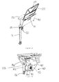
- FIG 3 shows the table arrangement 100 in place in an aircraft seat module 200.
- the aircraft set module comprises a seat 201 with an exterior shell 202 behind the seat. It also comprises a side console 203 in which the table arrangement 100 is provided. In particular, it is noted that the side console 203 provides the housing 130 of the table arrangement 100.
- the table 120 is moved from a stowed position to a presented position (as in Figures 1a and 1b ) by opening door 110. This causes the table to automatically move up to the presented position. From here, a user/passenger can pull the table up to the partially deployed position (as in Figure 2a and 2c ). This action requires the user to lift the table substantially vertically.
- the compensation arrangement (the spool 163 and band 164) assist in this by providing a spring force to counter act against the weight of the table 120, as described above. The user can then pivot the table 120 to a fully deployed horizontal position (as in Figures 2b and 2d ).
- the table 120 To stow the table 120, it is pivoted to its angled partially deployed position, and then pushed back into (or allowed to drop back into) the presented position. As the table 120 drops back down, the band 164 is unwound from the spool 163, which causes the shaft 162 to rotate. The rotary damper 165 damps the rotation of the shaft 162 so as to slow down the table as it drops to the presented position, as described above. From there, the door 110 is shut which automatically drops the table 120 back down to the stowed position.
Landscapes
- Engineering & Computer Science (AREA)
- Transportation (AREA)
- Mechanical Engineering (AREA)
- Aviation & Aerospace Engineering (AREA)
- Passenger Equipment (AREA)
Abstract
Description
- The present invention concerns a table arrangement for use in an aircraft seat module. More particularly, but not exclusively, this invention concerns the table arrangement comprising a table mounting structure, a table moveably mounted to the table mounting structure such that it can move between a lowered position and a raised position, a compensation arrangement connected between the table and table mounting structure for reducing the force required to lift the table from the lowered position to the raised position, and a damper arrangement for reducing the speed of the table as it moves from the raised position to the lowered position. The invention also concerns an aircraft seat module and a method of deploying or stowing a table arrangement.
- A prior art table arrangement comprises a table and table mounting structure where a constant force sprung band wound around a spool (compensation arrangement) is used to assist in the raising of the table from a lowered position to a raised position. The spool is rotatably mounted to the table mounting structure and a free end of the sprung band is attached to the table. The compensation arrangement acts to help pull the table up to the raised position.
- In addition, there is also a damping arrangement to slow down the table as it falls from its raised position to its lowered position. The damping arrangement comprises a rack and pinion mechanism, with the rack mounted to the table mounting structure. The rack is a vertical bar with a mesh on one side of it. A cog (with corresponding teeth to the mesh) is rotatably mounted on the table such that the teeth interlock with the mesh of the rack. Hence, the cog on the table rotates as the table moves up and down in relation to the rack. The cog's rotation on its axis is damped by a rotary damper.
- The rack and pinion mechanism can often be heavier and more complicated than is ideal. This adds weight to the table arrangement (especially undesirable in relation to an aircraft seat module) and can make maintenance, manufacture and repair more complicated and time-consuming, and therefore, more expensive.
- The present invention seeks to mitigate the above-mentioned problems. Alternatively or additionally, the present invention seeks to provide an improved table arrangement.
- The present invention provides, according to a first aspect, a table arrangement for use in an aircraft seat module, the table arrangement comprising a table mounting structure, a table moveably mounted to the table mounting structure such that it can move between a lowered position and a raised position, a compensation arrangement connected between the table and table mounting structure for reducing the force required to lift the table from the lowered position to the raised position, and a damper arrangement for reducing the speed of the table as it moves from the raised position to the lowered position, wherein the compensation arrangement is mounted on a shaft, such that as the table is lowered, the shaft rotates about its longitudinal axis and wherein the damping arrangement is arranged to act on the shaft to reduce the speed of its rotation about its longitudinal axis.
- This allows the damping arrangement to be much smaller as there is no need for a separate rack and pinion mechanism, for example. I.e. instead of providing damping in relation to a separate movement (the table in relation to the rack of the table mounting structure), the damping is provided by damping an existing shaft (associated with the compensation arrangement).
- Importantly, the damping arrangement acts on the shaft associated with the compensation arrangement. It does not simply provide damping elsewhere, for example on a separate arrangement between the table and table mounting structure (that inevitably may also damp the rotation of the shaft).
- Preferably, the damping arrangement acts directly on the shaft.
- Preferably, the damping arrangement is uni-directional. In other words, it only reduces the speed of the table as it moves from the raised position to the lowered position - it does not reduce the speed of the table as it moves from the lowered position to the raised position.
- Preferably, the compensation arrangement comprises a spool mounted on the shaft and an elongate member for winding onto and unwinding from the spool during lowering and raising of the table, wherein the compensation arrangement is biased such that the elongate member is urged to wind onto or unwind from the spool.
- More preferably, lowering and raising of the table causes winding onto and unwinding from the spool by the elongate member, and rotation of the spool.
- Even more preferably, the elongate member winds onto the spool during raising of the table. In this case, the elongate member unwinds from the spool during lowering of the table.
- Preferably, the spool is fixedly mounted on the shaft such that rotation of the spool causes rotation of the shaft about its longitudinal axis.
- Preferably, the elongate member is biased to wind onto the spool. If the elongate member winds onto the spool during raising of the table, this biases the table to the raised position.
- More preferably, the elongate member is urged to wind onto the spool by a spring returning towards its default position, and wherein the spring is tensioned away from its default position when the elongate member is unwound from the spool.
- Even more preferably, the elongate member comprises the spring. Even more preferably, the elongate member is the spring.
- Preferably, the shaft is caused to rotate by the compensation arrangement.
- Preferably, the shaft is mounted to the table and a free end of the elongate member is attached to the table mounting structure.
- Preferably, the damping arrangement comprises a rotary damper mounted on the shaft, coaxially with the compensation arrangement. More preferably, the damping arrangement and the compensation arrangement are close to each other (proximate). Even more preferably, the damping arrangement and the compensation arrangement are at the same end of the table (or table mounting structure) as each other. Even more preferably, the damping arrangement and the compensation arrangement are directly adjacent to each other.
- Preferably, the direction of table movement between the lowered and raised positions is approximately within the plane of the table. In other words, the table does not move substantially out of its plane between the lowered and raised positions. This means that the table movement between these positions requires only a small space. For example, the table could be vertical and move vertically from the lowered position to the raised position, thus only needing a small space in order to provide for this movement.
- Preferably, the table mounting structure comprises a housing which stows the table in the lowered position.
- Preferably, the table is slidably mounted to the table mounting structure with a cam follower and cam track arrangement.
- Preferably, the raised position is a deployed position and the lowered position is a stowed position.
- More preferably, the raised position is a partly deployed position. In other words, the table is further moved from the raised position to a fully deployed position.
- Even more preferably, the table will fall under its own weight (under gravity) from the raised position to the lowered position and wherein the table needs to be assisted by a user to move it from the fully deployed position to the raised position. For example, the table may be held by gravity in the fully deployed (for example, horizontal) position, by use of a stop. The table then needs to be rotated towards the raised position (for example, substantially vertical) so that it reaches past a "tipping point" and falls under gravity to the lowered position.
- According to a second aspect of the invention there is also provided an aircraft seat module comprising a seat, and a table arrangement as described above, and wherein the table mounting structure is mounted to the aircraft seat module.
- Preferably, the table is arranged such that it moves substantially vertically between the lowered and raised positions.
- According to a third aspect of the invention there is also provided an aircraft comprising a table arrangement or aircraft seat module as described above.
- According to a fourth aspect of the invention there is also provided a method of deploying and stowing a table arrangement of an aircraft seat module, the table arrangement comprising a table mounting structure and a table moveably mounted to the table mounting structure such that it can move between a lowered stowed position and a raised at least partly deployed position, a compensation arrangement connected between the table and table mounting structure and mounted on a shaft, and a damping arrangement, the method comprising the steps of raising the table, with the assistance of the compensation arrangement, from the lowered position to the raised position, and lowering the table, with the assistance of gravity, thus causing the shaft to rotate and the damper arrangement to act on the shaft to reduce the speed of its rotation about its longitudinal axis, thereby reducing the speed of the table as it moves from the raised position to the lowered position.
- The movement of the table from a stowed position (where the table is flush with or beneath a housing) to a presented position (where the table is protruding from the housing such that it can be pulled up and be raised into a deployed position) is described and claimed in UK patent application entitled "A Table Arrangement" with agent's reference "P022768GB ECT", having the same filing date as the present application. The contents of that application are fully incorporated herein by reference. The claims of the present application may incorporate any of the features disclosed in that patent application.
- It will of course be appreciated that features described in relation to one aspect of the present invention may be incorporated into other aspects of the present invention. For example, the method of the invention may incorporate any of the features described with reference to the apparatus of the invention and vice versa.
- Embodiments of the present invention will now be described by way of example only with reference to the accompanying schematic drawings of which:
- Figure 1a
- shows a perspective view of a table arrangement according to a first embodiment of the invention, in a presented configuration;
- Figure 1b
- shows an enlarged view of a damping and compensation arrangement of part of the table arrangement of
Figure 1a , in the presented configuration; - Figure 2a
- shows a perspective view of the table arrangement in fully deployed configuration;
- Figure 2b
- shows an enlarged view of the damping and compensation arrangement in the partially deployed configuration;
- Figure 2c
- shows a different perspective view of the table arrangement in the partially deployed configuration;
- Figure 2d
- shows a different enlarged view of the damping and compensation arrangement in the fully deployed configuration; and
- Figure 3
- shows a perspective view of the table arrangement in the partially deployed configuration, mounted in an aircraft seat module.
-
Figures 1a and 1b show views of atable arrangement 100 according to a first embodiment of the invention, in a presented configuration. - The
table arrangement 100 comprises adoor 110 with a rectangularfront face 112, aleft side panel 113 and aright side panel 114. A handle 111 is located towards the top of thefront face 112. Thedoor 110 is pivotally mounted to atable housing 130. The door is pivotally mounted byhinges 117 on the twoside panels door 110 also has a cam track (not shown) on the internally facing surface of theside panel 114. - Here, the
door 110 has been opened by pulling on the handle 111 to pivot thedoor 110 on thehinges 117 by approximately 20 to 30 degrees. - A table 120 is presented in the
housing 130 at substantially at the same angle as thedoor 110, with the top edge protruding above a top portion of thedoor 110. The table has a working table surface 121 (shown inFigure 2a ) and an underneath surface 121 (seen inFigure 1a , among others). The table 120 also comprises afinger hold 129 on its underneathsurface 122 for allowing a user/passenger to pull the table 120 out of thehousing 130. - A
mechanical linkage 140 connects the table 120 to thedoor 110 such that opening the door automatically moves the table from a stowed position to this presented position, where the top edge of the table protrudes above thedoor 110. Themechanical linkage 140 is connected to anactivation portion 125 of the table 120 at the bottom of thehousing 130. - A damping and
compensation arrangement 160 is connected between the table 120 and thehousing 130 to reduce the speed of the table 120 when it is dropped from a deployed or the presented position to the stowed position and to allow the table 120 to be lifted more easily from the presented position to a partially deployed position (inFigures 2a to 2d ). - The damping and
compensation arrangement 160 comprises aframe 161, attached to the table 120 and mounted on aslide 131 of thehousing 130. Theframe 161 rises when the table 120 rises and lowers when the table 120 lowers. - On the frame is a
rotatable shaft 162. On theshaft 162 is fixedly mounted aspool 163. The spool has aband 164 wound onto it, with one end portion of the band being wound 164a on the spool and the opposite end portion 164b being unwound from thespool 163. The opposite end of theband 164 is fixedly attached at 166 to thehousing 130. - The
band 164 us a constant force spring that is biased to be wound onto thespool 163. The spring force is less than the weight of the table, so that it counter acts most of the weight of the table but a small force is still needed by the user to raise the table. - A uni-directional
rotary damper 165 is mounted on thesame shaft 162 and can damp the rotation of theshaft 162 when it rotates in a given direction (the direction of theshaft 162 when the band unwinds). - From the presented position, a user/passenger can lift the table 120 (by pulling on finger hold 129) to the partially deployed position of
Figures 2a and2c . The table 120 is provided with a cam follower nodule (not shown) that is arranged inside the cam track of thedoor 110. Hence, when pulling on the table 120, the table 120 follows the path dictated by the cam track. - When the table rises (pulled up by a user), the
spring band 164 is wound onto the spool (biased to do so) and the spool rotates in a first direction, rotating theshaft 162 in the same direction. This releases tension in thespring band 164 towards its default (retracted/wound) position. - When the table lowers (allowed to fall under gravity), the
spring band 164 is unwound the spool (tensioning the band away from its default wound position) and the spool rotates in an opposite direction, rotating theshaft 162 in the same opposite direction. Therotary damper 165 damps the rotation of the shaft when it rotates in this opposite direction. Hence, the rotation of thespool 163 is slowed down and the unwinding of theband 164 is slowed down. This slows down the speed of the lowering table 120. Importantly, the overall net downwards force of the table 120 (its weight minus the tensioning of the internal spring and the force from the rotary damper 165) is still positive and so the table still lowers without additional force from the user. -
Figure 3 shows thetable arrangement 100 in place in anaircraft seat module 200. The aircraft set module comprises aseat 201 with anexterior shell 202 behind the seat. It also comprises aside console 203 in which thetable arrangement 100 is provided. In particular, it is noted that theside console 203 provides thehousing 130 of thetable arrangement 100. - In use, the table 120 is moved from a stowed position to a presented position (as in
Figures 1a and 1b ) by openingdoor 110. This causes the table to automatically move up to the presented position. From here, a user/passenger can pull the table up to the partially deployed position (as inFigure 2a and2c ). This action requires the user to lift the table substantially vertically. The compensation arrangement (thespool 163 and band 164) assist in this by providing a spring force to counter act against the weight of the table 120, as described above. The user can then pivot the table 120 to a fully deployed horizontal position (as inFigures 2b and2d ). - To stow the table 120, it is pivoted to its angled partially deployed position, and then pushed back into (or allowed to drop back into) the presented position. As the table 120 drops back down, the
band 164 is unwound from thespool 163, which causes theshaft 162 to rotate. Therotary damper 165 damps the rotation of theshaft 162 so as to slow down the table as it drops to the presented position, as described above. From there, thedoor 110 is shut which automatically drops the table 120 back down to the stowed position. - Whilst the present invention has been described and illustrated with reference to particular embodiments, it will be appreciated by those of ordinary skill in the art that the invention lends itself to many different variations not specifically illustrated herein.
- Where in the foregoing description, integers or elements are mentioned which have known, obvious or foreseeable equivalents, then such equivalents are herein incorporated as if individually set forth. Reference should be made to the claims for determining the true scope of the present invention, which should be construed so as to encompass any such equivalents. It will also be appreciated by the reader that integers or features of the invention that are described as preferable, advantageous, convenient or the like are optional and do not limit the scope of the independent claims. Moreover, it is to be understood that such optional integers or features, whilst of possible benefit in some embodiments of the invention, may not be desirable, and may therefore be absent, in other embodiments.
Claims (15)
- A table arrangement for use in an aircraft seat module, the table arrangement comprising:- a table mounting structure,- a table moveably mounted to the table mounting structure such that it can move between a lowered position and a raised position,- a compensation arrangement connected between the table and table mounting structure for reducing the force required to lift the table from the lowered position to the raised position, and- a damper arrangement for reducing the speed of the table as it moves from the raised position to the lowered position,wherein the compensation arrangement is mounted on a shaft, such that as the table is lowered, the shaft rotates about its longitudinal axis and wherein the damping arrangement is arranged to act on the shaft to reduce the speed of its rotation about its longitudinal axis.
- A table arrangement as claimed in claim 1, wherein the compensation arrangement comprises a spool mounted on the shaft and an elongate member for winding onto and unwinding from the spool during lowering and raising of the table, wherein the compensation arrangement is biased such that the elongate member is urged to wind onto or unwind from the spool.
- A table arrangement as claimed in claim 2, wherein lowering and raising of the table causes winding onto and unwinding from the spool by the elongate member, and rotation of the spool.
- A table arrangement as claimed in claim 3, wherein the elongate member winds onto the spool during raising of the table.
- A table arrangement as claimed in claim 3 or claim 4, wherein the spool is fixedly mounted on the shaft such that rotation of the spool causes rotation of the shaft about its longitudinal axis.
- A table arrangement as claimed in any of claims 2 to 5, wherein the elongate member is biased to wind onto the spool.
- A table arrangement as claimed in claim 6, wherein the elongate member is urged to wind onto the spool by a spring returning towards its default position, and wherein the spring is tensioned away from its default position when the elongate member is unwound from the spool.
- A table arrangement as claimed in any of claims 2 to 7, wherein the shaft is mounted to the table and a free end of the elongate member is attached to the table mounting structure.
- A table arrangement as claimed in any preceding claim, wherein the damping arrangement comprises a rotary damper mounted on the shaft, coaxially with the compensation arrangement.
- A table arrangement as claimed in any preceding claim, wherein the raised position is a deployed position and the lowered position is a stowed position.
- A table arrangement as claimed in claim 10, wherein the raised position is a partly deployed position.
- An aircraft seat module comprising:- a seat, and- a table arrangement of any preceding claim, andwherein the table mounting structure is mounted to the aircraft seat module.
- An aircraft seat module as claimed in claim 12, wherein the table is arranged such that it moves substantially vertically between the lowered and raised positions.
- An aircraft comprising a table arrangement or aircraft seat module of any preceding claim.
- A method of deploying and stowing a table arrangement of an aircraft seat module, the table arrangement comprising a table mounting structure and a table moveably mounted to the table mounting structure such that it can move between a lowered stowed position and a raised at least partly deployed position, a compensation arrangement connected between the table and table mounting structure and mounted on a shaft, and a damping arrangement,
the method comprising the steps of:- raising the table, with the assistance of the compensation arrangement, from the lowered position to the raised position, and- lowering the table, with the assistance of gravity, thus causing the shaft to rotate and the damper arrangement to act on the shaft to reduce the speed of its rotation about its longitudinal axis, thereby reducing the speed of the table as it moves from the raised position to the lowered position.
Applications Claiming Priority (1)
| Application Number | Priority Date | Filing Date | Title |
|---|---|---|---|
| GB1406239.2A GB2525381A (en) | 2014-04-07 | 2014-04-07 | A table arrangement |
Publications (2)
| Publication Number | Publication Date |
|---|---|
| EP2930112A1 true EP2930112A1 (en) | 2015-10-14 |
| EP2930112B1 EP2930112B1 (en) | 2017-01-25 |
Family
ID=50776943
Family Applications (1)
| Application Number | Title | Priority Date | Filing Date |
|---|---|---|---|
| EP15275112.9A Active EP2930112B1 (en) | 2014-04-07 | 2015-04-07 | A table arrangement |
Country Status (3)
| Country | Link |
|---|---|
| US (1) | US9731829B2 (en) |
| EP (1) | EP2930112B1 (en) |
| GB (1) | GB2525381A (en) |
Cited By (1)
| Publication number | Priority date | Publication date | Assignee | Title |
|---|---|---|---|---|
| EP3205579A1 (en) * | 2016-02-11 | 2017-08-16 | Thompson Aero Seating Limited | Deployable table |
Families Citing this family (13)
| Publication number | Priority date | Publication date | Assignee | Title |
|---|---|---|---|---|
| AT516253B1 (en) * | 2014-11-14 | 2016-04-15 | Facc Ag | folding table |
| FR3032178B1 (en) * | 2015-02-04 | 2017-03-03 | Dassault Aviat | AIRCRAFT CABIN INTERIOR DEVELOPMENT ASSEMBLY AND METHOD THEREOF |
| US10660809B2 (en) | 2015-09-11 | 2020-05-26 | Stryker Corporation | Telescoping assembly for use on a patient support apparatus |
| KR101904399B1 (en) * | 2016-12-16 | 2018-11-21 | 오형종 | seat back table in vehicle |
| US10442537B2 (en) * | 2017-07-20 | 2019-10-15 | Johnny A. Satterfield | Deployable table assembly |
| KR101996817B1 (en) * | 2017-11-09 | 2019-07-08 | 주식회사 서연이화 | Console table device of car |
| US10589652B2 (en) | 2017-12-18 | 2020-03-17 | Jvis-Usa, Llc | Mechanized tray table assembly |
| US10384581B2 (en) | 2017-12-18 | 2019-08-20 | Jvis-Usa, Llc | Powered mechanized tray table assembly |
| US11124301B2 (en) * | 2018-12-13 | 2021-09-21 | B/E Aerospace, Inc. | Tiered passenger seat console assembly |
| GB2598170B (en) * | 2021-01-07 | 2022-08-10 | Kotobuki & Co Ltd | A Seating Accessory Joint |
| US12151816B2 (en) * | 2022-10-11 | 2024-11-26 | B/E Aerospace, Inc. | Console mounted tray table with helical pivot |
| US12522359B2 (en) * | 2024-01-03 | 2026-01-13 | B/E Aerospace, Inc. | Meal table with rotational lifting assistance |
| US20250236390A1 (en) * | 2024-01-24 | 2025-07-24 | Textron Aviation Inc. | Aircraft Side Ledge Table Deployment System |
Citations (3)
| Publication number | Priority date | Publication date | Assignee | Title |
|---|---|---|---|---|
| GB2193744A (en) * | 1986-07-31 | 1988-02-17 | Schlegel Corp | Counterbalancing windows |
| US5311827A (en) * | 1992-06-18 | 1994-05-17 | Greene H Peter | Load compensator for spring counter-weighting mechanism |
| US20100326333A1 (en) * | 2009-06-29 | 2010-12-30 | St Louis Matthew | Aircraft table system with spring elements |
Family Cites Families (16)
| Publication number | Priority date | Publication date | Assignee | Title |
|---|---|---|---|---|
| JPH09136576A (en) * | 1995-11-15 | 1997-05-27 | Kanto Auto Works Ltd | Lid opening/closing mechanism |
| JP2002166771A (en) * | 2000-11-30 | 2002-06-11 | Johnson Controls Automotive Systems Corp | Table structure of seat |
| EP1836927B1 (en) * | 2006-03-22 | 2013-06-05 | Lufthansa Technik AG | Foldable table |
| FR2905355B1 (en) * | 2006-08-31 | 2009-05-22 | Airbus Groupement D Interet Ec | AIRCRAFT CAR AND AIRCRAFT CABIN SUB-ASSEMBLY COMPRISING SUCH A SUBSET |
| US8205563B2 (en) * | 2009-06-29 | 2012-06-26 | St. Louis Designs, Inc. | Aircraft table system with rolling sled member |
| JP5607333B2 (en) * | 2009-10-07 | 2014-10-15 | テイ・エス テック株式会社 | Folding table |
| WO2011133969A1 (en) * | 2010-04-23 | 2011-10-27 | Weber Aircraft Llc | Tray table stop assembly |
| WO2012021437A1 (en) * | 2010-08-09 | 2012-02-16 | Be Aerospace, Inc. | Deployable in-seat cup holder |
| US8528968B2 (en) * | 2010-11-30 | 2013-09-10 | Be Aerospace, Inc. | Stowable passenger seat tray table |
| US9010852B1 (en) * | 2011-12-19 | 2015-04-21 | TIMCO Aviation Services | In-arm monitor seat |
| DE102012012850B4 (en) * | 2012-06-26 | 2015-01-08 | Johnson Controls Gmbh | vehicle seat |
| CN106740348A (en) * | 2013-04-04 | 2017-05-31 | B/E航空公司 | It is capable of the tray-top table component of the vertical folding and unfolding of translational motion |
| CN105338859B (en) * | 2013-04-04 | 2019-12-20 | B/E航空公司 | Passenger seat with descending armrest assembly |
| CA3110924C (en) * | 2013-05-15 | 2023-04-11 | Bombardier Inc. | Exit row table for an aircraft |
| EP3024727A1 (en) * | 2013-07-24 | 2016-06-01 | Zodiac Seats US LLC | Tray table assembly |
| GB2525380A (en) * | 2014-04-07 | 2015-10-28 | Zodiac Seats Uk Ltd | A table arrangement |
-
2014
- 2014-04-07 GB GB1406239.2A patent/GB2525381A/en not_active Withdrawn
-
2015
- 2015-04-06 US US14/679,117 patent/US9731829B2/en not_active Expired - Fee Related
- 2015-04-07 EP EP15275112.9A patent/EP2930112B1/en active Active
Patent Citations (3)
| Publication number | Priority date | Publication date | Assignee | Title |
|---|---|---|---|---|
| GB2193744A (en) * | 1986-07-31 | 1988-02-17 | Schlegel Corp | Counterbalancing windows |
| US5311827A (en) * | 1992-06-18 | 1994-05-17 | Greene H Peter | Load compensator for spring counter-weighting mechanism |
| US20100326333A1 (en) * | 2009-06-29 | 2010-12-30 | St Louis Matthew | Aircraft table system with spring elements |
Cited By (1)
| Publication number | Priority date | Publication date | Assignee | Title |
|---|---|---|---|---|
| EP3205579A1 (en) * | 2016-02-11 | 2017-08-16 | Thompson Aero Seating Limited | Deployable table |
Also Published As
| Publication number | Publication date |
|---|---|
| US20150284091A1 (en) | 2015-10-08 |
| GB201406239D0 (en) | 2014-05-21 |
| US9731829B2 (en) | 2017-08-15 |
| GB2525381A (en) | 2015-10-28 |
| EP2930112B1 (en) | 2017-01-25 |
Similar Documents
| Publication | Publication Date | Title |
|---|---|---|
| EP2930112B1 (en) | A table arrangement | |
| EP2930111B1 (en) | A table arrangement | |
| CN107002440B (en) | Arrangement comprising a furniture door and a cavity, and drive device therefor | |
| JP5638288B2 (en) | Window shade device for vehicle | |
| CN107864648B (en) | Folding table | |
| CN103108761B (en) | Visor mechanism | |
| US20160222723A1 (en) | Cordless shade automatic lift regulator | |
| JP3201418U (en) | Lifting control structure for cordless blinds | |
| US7950438B2 (en) | Doorway screening apparatus | |
| CN102686427B (en) | Sunshade device | |
| KR20140002805U (en) | The Opening and Closing Structure of Manual Hatch For Offshore Platform | |
| US9145093B1 (en) | Trunk server/butler | |
| EP1980690A2 (en) | Engine hood door including variable door handle | |
| DE202012005606U1 (en) | Furniture and device for moving a furniture flap of a piece of furniture | |
| KR101581881B1 (en) | Automatically Monitor Receiving Type Desk | |
| JP2020026331A (en) | Dust collection booth | |
| JP3171217U (en) | Wheelchair storage device | |
| DE102013006759A1 (en) | Arrangement for shadowing disk of motor car, has flap covering roller blind device and positioned between stowing away position and guard position, and folding kinematics part fixed with closure flap and located in intermediate position | |
| KR20190074033A (en) | Wheelchair loading appatatus for vehicle | |
| JP4686334B2 (en) | Non-rail sliding door closer mechanism | |
| JPH0572350U (en) | Lid device | |
| JP2000279237A (en) | Movable storage device | |
| JP4786944B2 (en) | Sliding door retractor | |
| JP5758782B2 (en) | Window shade device | |
| JPH07331951A (en) | Overhead door |
Legal Events
| Date | Code | Title | Description |
|---|---|---|---|
| PUAI | Public reference made under article 153(3) epc to a published international application that has entered the european phase |
Free format text: ORIGINAL CODE: 0009012 |
|
| AK | Designated contracting states |
Kind code of ref document: A1 Designated state(s): AL AT BE BG CH CY CZ DE DK EE ES FI FR GB GR HR HU IE IS IT LI LT LU LV MC MK MT NL NO PL PT RO RS SE SI SK SM TR |
|
| AX | Request for extension of the european patent |
Extension state: BA ME |
|
| 17P | Request for examination filed |
Effective date: 20160219 |
|
| RBV | Designated contracting states (corrected) |
Designated state(s): AL AT BE BG CH CY CZ DE DK EE ES FI FR GB GR HR HU IE IS IT LI LT LU LV MC MK MT NL NO PL PT RO RS SE SI SK SM TR |
|
| REG | Reference to a national code |
Ref country code: DE Ref legal event code: R079 Ref document number: 602015001364 Country of ref document: DE Free format text: PREVIOUS MAIN CLASS: B64D0011060000 Ipc: A47B0003000000 |
|
| GRAP | Despatch of communication of intention to grant a patent |
Free format text: ORIGINAL CODE: EPIDOSNIGR1 |
|
| RIC1 | Information provided on ipc code assigned before grant |
Ipc: A47B 3/14 20060101ALI20160715BHEP Ipc: B64D 11/06 20060101ALI20160715BHEP Ipc: A47B 3/00 20060101AFI20160715BHEP |
|
| INTG | Intention to grant announced |
Effective date: 20160817 |
|
| GRAS | Grant fee paid |
Free format text: ORIGINAL CODE: EPIDOSNIGR3 |
|
| STAA | Information on the status of an ep patent application or granted ep patent |
Free format text: STATUS: GRANT OF PATENT IS INTENDED |
|
| GRAA | (expected) grant |
Free format text: ORIGINAL CODE: 0009210 |
|
| STAA | Information on the status of an ep patent application or granted ep patent |
Free format text: STATUS: THE PATENT HAS BEEN GRANTED |
|
| AK | Designated contracting states |
Kind code of ref document: B1 Designated state(s): AL AT BE BG CH CY CZ DE DK EE ES FI FR GB GR HR HU IE IS IT LI LT LU LV MC MK MT NL NO PL PT RO RS SE SI SK SM TR |
|
| REG | Reference to a national code |
Ref country code: GB Ref legal event code: FG4D |
|
| REG | Reference to a national code |
Ref country code: CH Ref legal event code: EP |
|
| REG | Reference to a national code |
Ref country code: AT Ref legal event code: REF Ref document number: 863607 Country of ref document: AT Kind code of ref document: T Effective date: 20170215 |
|
| REG | Reference to a national code |
Ref country code: IE Ref legal event code: FG4D |
|
| REG | Reference to a national code |
Ref country code: DE Ref legal event code: R096 Ref document number: 602015001364 Country of ref document: DE |
|
| REG | Reference to a national code |
Ref country code: FR Ref legal event code: PLFP Year of fee payment: 3 |
|
| REG | Reference to a national code |
Ref country code: LT Ref legal event code: MG4D |
|
| REG | Reference to a national code |
Ref country code: NL Ref legal event code: MP Effective date: 20170125 |
|
| REG | Reference to a national code |
Ref country code: AT Ref legal event code: MK05 Ref document number: 863607 Country of ref document: AT Kind code of ref document: T Effective date: 20170125 |
|
| PG25 | Lapsed in a contracting state [announced via postgrant information from national office to epo] |
Ref country code: NL Free format text: LAPSE BECAUSE OF FAILURE TO SUBMIT A TRANSLATION OF THE DESCRIPTION OR TO PAY THE FEE WITHIN THE PRESCRIBED TIME-LIMIT Effective date: 20170125 |
|
| REG | Reference to a national code |
Ref country code: DE Ref legal event code: R082 Ref document number: 602015001364 Country of ref document: DE Representative=s name: SCHMITT-NILSON SCHRAUD WAIBEL WOHLFROM PATENTA, DE |
|
| PG25 | Lapsed in a contracting state [announced via postgrant information from national office to epo] |
Ref country code: LT Free format text: LAPSE BECAUSE OF FAILURE TO SUBMIT A TRANSLATION OF THE DESCRIPTION OR TO PAY THE FEE WITHIN THE PRESCRIBED TIME-LIMIT Effective date: 20170125 Ref country code: GR Free format text: LAPSE BECAUSE OF FAILURE TO SUBMIT A TRANSLATION OF THE DESCRIPTION OR TO PAY THE FEE WITHIN THE PRESCRIBED TIME-LIMIT Effective date: 20170426 Ref country code: NO Free format text: LAPSE BECAUSE OF FAILURE TO SUBMIT A TRANSLATION OF THE DESCRIPTION OR TO PAY THE FEE WITHIN THE PRESCRIBED TIME-LIMIT Effective date: 20170425 Ref country code: HR Free format text: LAPSE BECAUSE OF FAILURE TO SUBMIT A TRANSLATION OF THE DESCRIPTION OR TO PAY THE FEE WITHIN THE PRESCRIBED TIME-LIMIT Effective date: 20170125 Ref country code: IS Free format text: LAPSE BECAUSE OF FAILURE TO SUBMIT A TRANSLATION OF THE DESCRIPTION OR TO PAY THE FEE WITHIN THE PRESCRIBED TIME-LIMIT Effective date: 20170525 Ref country code: FI Free format text: LAPSE BECAUSE OF FAILURE TO SUBMIT A TRANSLATION OF THE DESCRIPTION OR TO PAY THE FEE WITHIN THE PRESCRIBED TIME-LIMIT Effective date: 20170125 |
|
| PG25 | Lapsed in a contracting state [announced via postgrant information from national office to epo] |
Ref country code: AT Free format text: LAPSE BECAUSE OF FAILURE TO SUBMIT A TRANSLATION OF THE DESCRIPTION OR TO PAY THE FEE WITHIN THE PRESCRIBED TIME-LIMIT Effective date: 20170125 Ref country code: SE Free format text: LAPSE BECAUSE OF FAILURE TO SUBMIT A TRANSLATION OF THE DESCRIPTION OR TO PAY THE FEE WITHIN THE PRESCRIBED TIME-LIMIT Effective date: 20170125 Ref country code: PL Free format text: LAPSE BECAUSE OF FAILURE TO SUBMIT A TRANSLATION OF THE DESCRIPTION OR TO PAY THE FEE WITHIN THE PRESCRIBED TIME-LIMIT Effective date: 20170125 Ref country code: BG Free format text: LAPSE BECAUSE OF FAILURE TO SUBMIT A TRANSLATION OF THE DESCRIPTION OR TO PAY THE FEE WITHIN THE PRESCRIBED TIME-LIMIT Effective date: 20170425 Ref country code: ES Free format text: LAPSE BECAUSE OF FAILURE TO SUBMIT A TRANSLATION OF THE DESCRIPTION OR TO PAY THE FEE WITHIN THE PRESCRIBED TIME-LIMIT Effective date: 20170125 Ref country code: PT Free format text: LAPSE BECAUSE OF FAILURE TO SUBMIT A TRANSLATION OF THE DESCRIPTION OR TO PAY THE FEE WITHIN THE PRESCRIBED TIME-LIMIT Effective date: 20170525 Ref country code: RS Free format text: LAPSE BECAUSE OF FAILURE TO SUBMIT A TRANSLATION OF THE DESCRIPTION OR TO PAY THE FEE WITHIN THE PRESCRIBED TIME-LIMIT Effective date: 20170125 Ref country code: LV Free format text: LAPSE BECAUSE OF FAILURE TO SUBMIT A TRANSLATION OF THE DESCRIPTION OR TO PAY THE FEE WITHIN THE PRESCRIBED TIME-LIMIT Effective date: 20170125 |
|
| REG | Reference to a national code |
Ref country code: DE Ref legal event code: R097 Ref document number: 602015001364 Country of ref document: DE |
|
| PG25 | Lapsed in a contracting state [announced via postgrant information from national office to epo] |
Ref country code: EE Free format text: LAPSE BECAUSE OF FAILURE TO SUBMIT A TRANSLATION OF THE DESCRIPTION OR TO PAY THE FEE WITHIN THE PRESCRIBED TIME-LIMIT Effective date: 20170125 Ref country code: CZ Free format text: LAPSE BECAUSE OF FAILURE TO SUBMIT A TRANSLATION OF THE DESCRIPTION OR TO PAY THE FEE WITHIN THE PRESCRIBED TIME-LIMIT Effective date: 20170125 Ref country code: RO Free format text: LAPSE BECAUSE OF FAILURE TO SUBMIT A TRANSLATION OF THE DESCRIPTION OR TO PAY THE FEE WITHIN THE PRESCRIBED TIME-LIMIT Effective date: 20170125 Ref country code: SK Free format text: LAPSE BECAUSE OF FAILURE TO SUBMIT A TRANSLATION OF THE DESCRIPTION OR TO PAY THE FEE WITHIN THE PRESCRIBED TIME-LIMIT Effective date: 20170125 |
|
| PG25 | Lapsed in a contracting state [announced via postgrant information from national office to epo] |
Ref country code: DK Free format text: LAPSE BECAUSE OF FAILURE TO SUBMIT A TRANSLATION OF THE DESCRIPTION OR TO PAY THE FEE WITHIN THE PRESCRIBED TIME-LIMIT Effective date: 20170125 Ref country code: SM Free format text: LAPSE BECAUSE OF FAILURE TO SUBMIT A TRANSLATION OF THE DESCRIPTION OR TO PAY THE FEE WITHIN THE PRESCRIBED TIME-LIMIT Effective date: 20170125 |
|
| PLBE | No opposition filed within time limit |
Free format text: ORIGINAL CODE: 0009261 |
|
| STAA | Information on the status of an ep patent application or granted ep patent |
Free format text: STATUS: NO OPPOSITION FILED WITHIN TIME LIMIT |
|
| 26N | No opposition filed |
Effective date: 20171026 |
|
| REG | Reference to a national code |
Ref country code: IE Ref legal event code: MM4A |
|
| PG25 | Lapsed in a contracting state [announced via postgrant information from national office to epo] |
Ref country code: MC Free format text: LAPSE BECAUSE OF FAILURE TO SUBMIT A TRANSLATION OF THE DESCRIPTION OR TO PAY THE FEE WITHIN THE PRESCRIBED TIME-LIMIT Effective date: 20170125 |
|
| PG25 | Lapsed in a contracting state [announced via postgrant information from national office to epo] |
Ref country code: LU Free format text: LAPSE BECAUSE OF NON-PAYMENT OF DUE FEES Effective date: 20170407 Ref country code: SI Free format text: LAPSE BECAUSE OF FAILURE TO SUBMIT A TRANSLATION OF THE DESCRIPTION OR TO PAY THE FEE WITHIN THE PRESCRIBED TIME-LIMIT Effective date: 20170125 |
|
| REG | Reference to a national code |
Ref country code: FR Ref legal event code: PLFP Year of fee payment: 4 |
|
| REG | Reference to a national code |
Ref country code: BE Ref legal event code: MM Effective date: 20170430 |
|
| PG25 | Lapsed in a contracting state [announced via postgrant information from national office to epo] |
Ref country code: IE Free format text: LAPSE BECAUSE OF NON-PAYMENT OF DUE FEES Effective date: 20170407 |
|
| PG25 | Lapsed in a contracting state [announced via postgrant information from national office to epo] |
Ref country code: BE Free format text: LAPSE BECAUSE OF NON-PAYMENT OF DUE FEES Effective date: 20170430 |
|
| PG25 | Lapsed in a contracting state [announced via postgrant information from national office to epo] |
Ref country code: MT Free format text: LAPSE BECAUSE OF NON-PAYMENT OF DUE FEES Effective date: 20170407 |
|
| REG | Reference to a national code |
Ref country code: CH Ref legal event code: PL |
|
| PG25 | Lapsed in a contracting state [announced via postgrant information from national office to epo] |
Ref country code: CH Free format text: LAPSE BECAUSE OF NON-PAYMENT OF DUE FEES Effective date: 20180430 Ref country code: LI Free format text: LAPSE BECAUSE OF NON-PAYMENT OF DUE FEES Effective date: 20180430 |
|
| PG25 | Lapsed in a contracting state [announced via postgrant information from national office to epo] |
Ref country code: HU Free format text: LAPSE BECAUSE OF FAILURE TO SUBMIT A TRANSLATION OF THE DESCRIPTION OR TO PAY THE FEE WITHIN THE PRESCRIBED TIME-LIMIT; INVALID AB INITIO Effective date: 20150407 |
|
| PG25 | Lapsed in a contracting state [announced via postgrant information from national office to epo] |
Ref country code: CY Free format text: LAPSE BECAUSE OF FAILURE TO SUBMIT A TRANSLATION OF THE DESCRIPTION OR TO PAY THE FEE WITHIN THE PRESCRIBED TIME-LIMIT Effective date: 20170125 |
|
| PG25 | Lapsed in a contracting state [announced via postgrant information from national office to epo] |
Ref country code: MK Free format text: LAPSE BECAUSE OF FAILURE TO SUBMIT A TRANSLATION OF THE DESCRIPTION OR TO PAY THE FEE WITHIN THE PRESCRIBED TIME-LIMIT Effective date: 20170125 |
|
| PG25 | Lapsed in a contracting state [announced via postgrant information from national office to epo] |
Ref country code: TR Free format text: LAPSE BECAUSE OF FAILURE TO SUBMIT A TRANSLATION OF THE DESCRIPTION OR TO PAY THE FEE WITHIN THE PRESCRIBED TIME-LIMIT Effective date: 20170125 |
|
| PG25 | Lapsed in a contracting state [announced via postgrant information from national office to epo] |
Ref country code: AL Free format text: LAPSE BECAUSE OF FAILURE TO SUBMIT A TRANSLATION OF THE DESCRIPTION OR TO PAY THE FEE WITHIN THE PRESCRIBED TIME-LIMIT Effective date: 20170125 |
|
| REG | Reference to a national code |
Ref country code: DE Ref legal event code: R082 Ref document number: 602015001364 Country of ref document: DE Representative=s name: SCHMITT-NILSON SCHRAUD WAIBEL WOHLFROM PATENTA, DE Ref country code: DE Ref legal event code: R081 Ref document number: 602015001364 Country of ref document: DE Owner name: SAFRAN SEATS GB LTD., GB Free format text: FORMER OWNER: ZODIAC SEATS UK LTD., CWMBRAN, GB |
|
| PGFP | Annual fee paid to national office [announced via postgrant information from national office to epo] |
Ref country code: DE Payment date: 20230321 Year of fee payment: 9 |
|
| PGFP | Annual fee paid to national office [announced via postgrant information from national office to epo] |
Ref country code: IT Payment date: 20240320 Year of fee payment: 10 Ref country code: FR Payment date: 20240320 Year of fee payment: 10 |
|
| REG | Reference to a national code |
Ref country code: DE Ref legal event code: R119 Ref document number: 602015001364 Country of ref document: DE |
|
| PG25 | Lapsed in a contracting state [announced via postgrant information from national office to epo] |
Ref country code: DE Free format text: LAPSE BECAUSE OF NON-PAYMENT OF DUE FEES Effective date: 20251104 |
|
| PG25 | Lapsed in a contracting state [announced via postgrant information from national office to epo] |
Ref country code: FR Free format text: LAPSE BECAUSE OF NON-PAYMENT OF DUE FEES Effective date: 20250430 |
|
| PGFP | Annual fee paid to national office [announced via postgrant information from national office to epo] |
Ref country code: GB Payment date: 20260327 Year of fee payment: 12 |
|
| PG25 | Lapsed in a contracting state [announced via postgrant information from national office to epo] |
Ref country code: IT Free format text: LAPSE BECAUSE OF NON-PAYMENT OF DUE FEES Effective date: 20250407 |