EP2930092B1 - Foldable vehicle - Google Patents
Foldable vehicle Download PDFInfo
- Publication number
- EP2930092B1 EP2930092B1 EP14164491.4A EP14164491A EP2930092B1 EP 2930092 B1 EP2930092 B1 EP 2930092B1 EP 14164491 A EP14164491 A EP 14164491A EP 2930092 B1 EP2930092 B1 EP 2930092B1
- Authority
- EP
- European Patent Office
- Prior art keywords
- frame pipe
- vehicle
- lower frame
- foldable vehicle
- support portion
- Prior art date
- Legal status (The legal status is an assumption and is not a legal conclusion. Google has not performed a legal analysis and makes no representation as to the accuracy of the status listed.)
- Active
Links
Images


Classifications
-
- B—PERFORMING OPERATIONS; TRANSPORTING
- B62—LAND VEHICLES FOR TRAVELLING OTHERWISE THAN ON RAILS
- B62K—CYCLES; CYCLE FRAMES; CYCLE STEERING DEVICES; RIDER-OPERATED TERMINAL CONTROLS SPECIALLY ADAPTED FOR CYCLES; CYCLE AXLE SUSPENSIONS; CYCLE SIDE-CARS, FORECARS, OR THE LIKE
- B62K15/00—Collapsible or foldable cycles
- B62K15/006—Collapsible or foldable cycles the frame being foldable
-
- B—PERFORMING OPERATIONS; TRANSPORTING
- B62—LAND VEHICLES FOR TRAVELLING OTHERWISE THAN ON RAILS
- B62K—CYCLES; CYCLE FRAMES; CYCLE STEERING DEVICES; RIDER-OPERATED TERMINAL CONTROLS SPECIALLY ADAPTED FOR CYCLES; CYCLE AXLE SUSPENSIONS; CYCLE SIDE-CARS, FORECARS, OR THE LIKE
- B62K15/00—Collapsible or foldable cycles
- B62K2015/005—Collapsible or foldable cycles having additional wheels for use when folded or collapsed
Definitions
- the invention is related to the field of personal vehicles.
- the invention is related to a battery or mechanically powered, quickly foldable, light two-wheel or three-wheel individual vehicle.
- http://www.strida.com discloses a folding bicycle with a triangular frame.
- Publication JP S51 53337 A presents a foldable bicycle having a foldable frame.
- Publication JP 2002 160689 A also presents a foldable bicycle that has a frame the position of which can be changed between the unfolding and the folding positions.
- the invention provides a vehicle for comfortably covering short distances.
- the design of the vehicle allows to fold it easily and fast to save space.
- the advantages of the current invention The vehicle can be folded/packed up by releasing two locks from locking positions.
- the measures and proportions of the vehicle have been calculated so that in a riding position, the legs of an adult person can reach the leg supports, hands can reach the handlebars, and legs can reach the ground when stopped.
- the preferred embodiment of the invention can withstand loads up to 110 kg, despite the fact that the frame is made up of thin aluminium pipes.
- the triangular design of the middle part of the frame gives it strength and rigidity, along with the fact that elements of the frame are composed of two parallel elements.
- the vehicle of the invention provides an ergonomic riding position - the person sitting on the saddle is supported by his legs and hands.
- the invention also provides an ergonomic posture for the legs - thanks to the design of the pedals, they are located in a place where they ensure an ergonomic posture for the legs in the riding position.
- a sliding carriage on the frame is used to fold one part of the frame of the vehicle.
- the elements of the frame of the vehicle of the invention constitute a right triangle in middle of the frame where one arm is formed by the lower frame pipe part from the handlebar to leg supports and pedals, another arm is formed by the support element part between the saddle and the lower frame element, and the hypotenuse is formed by the upper frame pipe of the frame.
- the angle between the lower frame pipe and the support element of the frame of the vehicle of the invention can be less than 90° or greater than 90°.
- the goal of the present invention is to provide a vehicle design that overcomes the deficiencies of the solutions known in the art.
- the ergonomic riding position of the vehicle of the invention is achieved as a solution of the relationship between three points - the saddle, leg support and the vehicle's handlebar - whereby the weight of body is evenly distributed between these three supporting points so the load on each of these points is even. This is beneficial both for the rider and the vehicle.
- the vehicle of the invention includes:
- the location of the auxiliary wheel is designed so that the vehicle could be towed in its folded form by a regular size person, and that in the upright position (in which the vehicle takes least amount of space), the auxiliary wheels would serve as a supporting point.
- the distance between the auxiliary wheel and the rear wheel is designed so that the auxiliary wheels and the rear wheel work together to allow pulling the vehicle up the stairs so that first, the vehicle's wheel moves over the step, then the auxiliary wheels.
- the upper frame pipe has a handle for lifting the vehicle that works together with the locking device - by lifting the vehicle from the handle and holding it up, the lock of the locking device can be opened with the thumb of the same hand.
- the upright element connecting the front wheel fork and vehicle's handlebar starts towards the folded position due to gravity.
- the upright element connecting the front wheel fork and the vehicle's handlebar moves towards the unfolded position due to gravity.
- An important advantage is that lifting the entire vehicle is not needed; it is sufficient to keep the front part of the vehicle lifted up. It is also not necessary to keep the vehicle balanced because the balance is achieved through the auxiliary wheels that are resting on ground.
- a vehicle of the invention has a frame (1), front wheel (2), rear wheel (3), leg supports (4), handlebar (5), saddle (6), and auxiliary wheels (7).
- the handlebar (5) is connected to the front wheel fork (8) by an upright element (9).
- the frame comprises an upper frame pipe (10), a lower frame pipe (11), and a support element (12) between the saddle and the lower frame pipe.
- Auxiliary wheels (7) can be located at the distal end ( Fig. 2 ) of the upper frame pipe (10) or at the distal end of the lower frame pipe (11).
- the first end of the upper frame pipe (10) is connected to the lower frame pipe (11) by a hinge.
- the upper frame pipe (10) extends distally from the saddle at certain length.
- the hinge assembly comprises a connecting plate (14) with its edge connected to the upright element (9).
- the connecting plate is connected to the lower frame pipe (11) pivotally in relation to axis (15).
- the connecting plate has depressions (16) for receiving the locking bolt (17).
- the preferred embodiment has two depressions - one is for locking the vehicle in the riding position and the other is for locking the vehicle in the folded position.
- the bolt is pressed into the depression by a compression spring (18).
- the bolt can be actuated in its encasing (19) using the front trigger (20).
- the bolt (17) In the normal position, the bolt (17) is pressed to the bottom of the depression (16) by the compression spring; using the front trigger (20), the compression spring is compressed and the bolt moves out of the depression, allowing the connecting plate (14) to pivot in relation to the lower frame pipe (11). After releasing the front trigger, the bolt is pressed back into the depression by the compression spring.
- the upper frame pipe has a handle (21) near the front trigger to facilitate moving the front trigger (see Fig. 3 ). Another purpose of the handle is to allow easy folding of the vehicle. To fold the vehicle, it is sufficient to grab the handle with one hand while simultaneously pushing the front trigger; when the vehicle is slightly lifted, the front part of the vehicle smoothly moves into the locked position.
- the lower end of the support element (12) between the saddle and the lower frame pipe is pivotally connected to the lower frame pipe, while the upper end of the support pipe has a sliding carriage (22) (see Fig. 6 ).
- the saddle (6) is connected to the upper frame pipe (10) by the seatpost (23).
- the sliding carriage has a sliding sleeve (24) that is moveably connected to the upper frame pipe.
- the sliding carriage has a surface (25) for receiving the locking device (26).
- the locking device is pressed into the locking position by a locking spring (27) that can be compressed using the rear trigger (28).
- the trigger can be manipulated through an opening (29) made into the saddle.
- the seatpost (23) also acts to limit the movement of the sliding carriage (22) along the upper frame pipe (10).
- the saddle (6) is connected to the upper frame pipe; in an alternative embodiment, the seatpost (23) can be connected to the sliding carriage (22).
- the upper frame pipe has a limiter (not shown in the drawings) for the locking sliding carriage and locking the vehicle into the riding position.
- the leg supports (4) are connected to an extension of the support element (12) extending downwards from the lower frame pipe.
- the lower frame pipe (11) and support element (12) cross each other at an angle a that in a preferred embodiment is 90°; in alternative embodiments, the said angle can vary between 80-100°.
- the location of the auxiliary wheel is designed to allow a regular size adult person tow the folded vehicle so that the distance (H) of the handlebar of the folded vehicle from the ground would preferably be ca. 600mm ( Fig. 8 ).
- the upper frame element or saddle has a supporting device (now shown in drawings) that functions as a third foothold (in addition to the two auxiliary wheels (7)) for helping to maintain the stability of the upright position of the folded vehicle.
Description
- The invention is related to the field of personal vehicles. The invention is related to a battery or mechanically powered, quickly foldable, light two-wheel or three-wheel individual vehicle.
- http://www.strida.com discloses a folding bicycle with a triangular frame.
- http://www.carrymefoldingbike.com/ discloses a folding bicycle with training wheels.
- Publication
JP S51 53337 A JP 2002 160689 A - The solutions known in the art have some shortcomings:
- a) More than two operations are needed to fold the vehicle, or more time is needed to carry out each operation, and
- b) certain parts of the frame need to be disengaged to fold the vehicle.
- The invention provides a vehicle for comfortably covering short distances. The design of the vehicle allows to fold it easily and fast to save space.
- The advantages of the current invention:
The vehicle can be folded/packed up by releasing two locks from locking positions. - The measures and proportions of the vehicle have been calculated so that in a riding position, the legs of an adult person can reach the leg supports, hands can reach the handlebars, and legs can reach the ground when stopped.
- The preferred embodiment of the invention can withstand loads up to 110 kg, despite the fact that the frame is made up of thin aluminium pipes. The triangular design of the middle part of the frame gives it strength and rigidity, along with the fact that elements of the frame are composed of two parallel elements.
- The vehicle of the invention provides an ergonomic riding position - the person sitting on the saddle is supported by his legs and hands. The invention also provides an ergonomic posture for the legs - thanks to the design of the pedals, they are located in a place where they ensure an ergonomic posture for the legs in the riding position. A sliding carriage on the frame is used to fold one part of the frame of the vehicle. In the riding position, the elements of the frame of the vehicle of the invention constitute a right triangle in middle of the frame where one arm is formed by the lower frame pipe part from the handlebar to leg supports and pedals, another arm is formed by the support element part between the saddle and the lower frame element, and the hypotenuse is formed by the upper frame pipe of the frame. Alternatively, the angle between the lower frame pipe and the support element of the frame of the vehicle of the invention can be less than 90° or greater than 90°.
- The goal of the present invention is to provide a vehicle design that overcomes the deficiencies of the solutions known in the art. The ergonomic riding position of the vehicle of the invention is achieved as a solution of the relationship between three points - the saddle, leg support and the vehicle's handlebar - whereby the weight of body is evenly distributed between these three supporting points so the load on each of these points is even. This is beneficial both for the rider and the vehicle. The vehicle of the invention includes:
- a frame with:
- i) an upper frame pipe comprising two parallel parts, the front end of which is connected to the upright element connecting the fork of the front wheel and the vehicle's handlebar, with a certain part of the distal end of the upper frame pipe extending distally from under the saddle;
- ii) a lower frame pipe comprising two parallel parts, the front end on which is connected to the upright element connecting the fork of the front wheel and the vehicle's handlebar, with the rear wheel or wheels attached next to distal end of lower frame pipe for the transportation of the vehicle;
- iii) a support element between the saddle and the lower frame pipe comprising two parallel parts, with the support element extending to below the lower frame pipe so that the support element's lower can bear the leg supports;
- iv) a front wheel fork and handlebar connected to each other by means of an upright element.
- The design of the frame is characterized in that:
- i) the front end of the lower frame pipe has a swivelling hinge that is equipped with a hinge lock;
- ii) the end of the support element between the saddle and the lower frame pipe is pivotally connected to the lower frame pipe, the lower end of the support element extends below the lower frame pipe, forming leg supports, the upper end of the support element is equipped with a sliding carriage fixed to the upper frame pipe in the riding position, while in the folded position of the vehicle, the support element's upper end is shifted longitudinally along the upper frame pipe with the sliding carriage so that in the folded position, the upper and lower frame pipes and support element are essentially parallel;
- iii) the upright element connecting the front wheel fork with the vehicle's handlebar can be pivotally fixed in the riding position and/or the transport position so that in the folded position, the first wheel is turned towards the rear wheel and the vehicle's handlebar is turned forward, forming a transportation handle;
- iv) the saddle can be fixed either to the support element or alternatively to the upper frame pipe;
- v) the lower frame pipe and support element cross each other at an angle a that in a preferred embodiment is 90°, in alternative embodiments the said angle can vary between 80-100°.
- vi) the frame of the vehicle has auxiliary wheels for transportation, which are located at the distal part of the upper frame pipe in the preferred embodiment; alternatively, the auxiliary wheels can be located at the free end of the lower frame pipe, behind the rear wheel.
- The location of the auxiliary wheel is designed so that the vehicle could be towed in its folded form by a regular size person, and that in the upright position (in which the vehicle takes least amount of space), the auxiliary wheels would serve as a supporting point. The distance between the auxiliary wheel and the rear wheel is designed so that the auxiliary wheels and the rear wheel work together to allow pulling the vehicle up the stairs so that first, the vehicle's wheel moves over the step, then the auxiliary wheels.
- Another advantage of the invention is that the upper frame pipe has a handle for lifting the vehicle that works together with the locking device - by lifting the vehicle from the handle and holding it up, the lock of the locking device can be opened with the thumb of the same hand. When the vehicle is lifted by the handle and the lock unlocked, the upright element connecting the front wheel fork and vehicle's handlebar starts towards the folded position due to gravity. When unfolding the folded vehicle, the upright element connecting the front wheel fork and the vehicle's handlebar moves towards the unfolded position due to gravity. This ensures the ergonomics of the folding and unfolding steps due to the combination of the handle, the lock, the upright element connecting the front wheel fork and the vehicle's handlebar, the hinge between the upper frame pipe and the upright element connecting the front wheel fork and the vehicle's handlebar, and hand position. To complete the operation of folding up or unfolding the vehicle, it is easy to push the fork with the other hand so that it locks in the required position - either to lock it in the folded position or to lock it in the unfolded position.
- An important advantage is that lifting the entire vehicle is not needed; it is sufficient to keep the front part of the vehicle lifted up. It is also not necessary to keep the vehicle balanced because the balance is achieved through the auxiliary wheels that are resting on ground.
- The preferred embodiment of the invention is described in detail below, with reference to the attached figures, where:
-
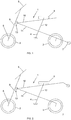
Fig. 1 depicts a schematic overview of one preferred version of the vehicle of the invention, with auxiliary wheels located at the end of the lower frame pipe; -
Fig. 2 depicts a schematic overview of another preferred version of a vehicle of the invention, with auxiliary wheels located at the end of upper frame pipe; -
Fig. 3 depicts a vehicle of the invention after the first stage of folding up; -
Fig. 4a depicts a vehicle of the invention with auxiliary wheels attached to the lower frame pipe after the second stage of folding up; -
Fig. 4b depicts a vehicle of the invention with auxiliary wheels attached to the upper frame pipe after the second stage of folding up; -
Fig. 5 depicts the triangle formed by the invented vehicle's frame; -
Fig. 6 depicts the upper end of the support pipe located between the saddle and the lower frame pipe of a vehicle of the invention; -
Fig. 7 depicts the front wheel with a fork and the pivoting connection of the upright pipe of the handlebar of a vehicle of the invention; -
Fig. 8 depicts the movement of a vehicle of the invention on stairs. - Referring to
Fig. 1 , a vehicle of the invention has a frame (1), front wheel (2), rear wheel (3), leg supports (4), handlebar (5), saddle (6), and auxiliary wheels (7). The handlebar (5) is connected to the front wheel fork (8) by an upright element (9). The frame comprises an upper frame pipe (10), a lower frame pipe (11), and a support element (12) between the saddle and the lower frame pipe. Auxiliary wheels (7) can be located at the distal end (Fig. 2 ) of the upper frame pipe (10) or at the distal end of the lower frame pipe (11). The first end of the upper frame pipe (10) is connected to the lower frame pipe (11) by a hinge. The upper frame pipe (10) extends distally from the saddle at certain length. There is a hinge assembly (13) between the first end of the lower frame pipe (11) and the upright element (9) (seeFig. 7a to 7c ). The hinge assembly comprises a connecting plate (14) with its edge connected to the upright element (9). The connecting plate is connected to the lower frame pipe (11) pivotally in relation to axis (15). The connecting plate has depressions (16) for receiving the locking bolt (17). The preferred embodiment has two depressions - one is for locking the vehicle in the riding position and the other is for locking the vehicle in the folded position. The bolt is pressed into the depression by a compression spring (18). The bolt can be actuated in its encasing (19) using the front trigger (20). In the normal position, the bolt (17) is pressed to the bottom of the depression (16) by the compression spring; using the front trigger (20), the compression spring is compressed and the bolt moves out of the depression, allowing the connecting plate (14) to pivot in relation to the lower frame pipe (11). After releasing the front trigger, the bolt is pressed back into the depression by the compression spring. The upper frame pipe has a handle (21) near the front trigger to facilitate moving the front trigger (seeFig. 3 ). Another purpose of the handle is to allow easy folding of the vehicle. To fold the vehicle, it is sufficient to grab the handle with one hand while simultaneously pushing the front trigger; when the vehicle is slightly lifted, the front part of the vehicle smoothly moves into the locked position. The lower end of the support element (12) between the saddle and the lower frame pipe is pivotally connected to the lower frame pipe, while the upper end of the support pipe has a sliding carriage (22) (seeFig. 6 ). The saddle (6) is connected to the upper frame pipe (10) by the seatpost (23). The sliding carriage has a sliding sleeve (24) that is moveably connected to the upper frame pipe. The sliding carriage has a surface (25) for receiving the locking device (26). The locking device is pressed into the locking position by a locking spring (27) that can be compressed using the rear trigger (28). The trigger can be manipulated through an opening (29) made into the saddle. The seatpost (23) also acts to limit the movement of the sliding carriage (22) along the upper frame pipe (10). In the preferred embodiment of the invention, the saddle (6) is connected to the upper frame pipe; in an alternative embodiment, the seatpost (23) can be connected to the sliding carriage (22). In that case, the upper frame pipe has a limiter (not shown in the drawings) for the locking sliding carriage and locking the vehicle into the riding position. The leg supports (4) are connected to an extension of the support element (12) extending downwards from the lower frame pipe. The lower frame pipe (11) and support element (12) cross each other at an angle a that in a preferred embodiment is 90°; in alternative embodiments, the said angle can vary between 80-100°. The location of the auxiliary wheel is designed to allow a regular size adult person tow the folded vehicle so that the distance (H) of the handlebar of the folded vehicle from the ground would preferably be ca. 600mm (Fig. 8 ). The upper frame element or saddle has a supporting device (now shown in drawings) that functions as a third foothold (in addition to the two auxiliary wheels (7)) for helping to maintain the stability of the upright position of the folded vehicle.
Claims (15)
- A foldable vehicle comprising a frame (1), a handlebar support portion for receiving a handlebar (5) at a front end of the frame (1), a front wheel support portion (8) for receiving a front wheet (2), a rear wheel support portion for receiving a rear wheel (3), at a distal end of the frame (1), a leg support portion (4) for receiving leg supports in a middle part of the frame (1), and a saddle support portion for receiving a saddle (6), a support element (12) between the saddle support portion and a lower frame pipe (11), the support element (12) being pivotally connected to the lower frame pipe (11), a lower part of the support element (12) having the leg support portion (4), characterized in that an upper part of the support element (12) has a sliding carriage (22) that is moveable along an upper frame pipe (10) and can be locked and unlocked to the upper frame pipe (10), and a connecting plate (14) is located at a handlebar side of the lower frame pipe (11) and configured to lock an upright element (9) connecting the front wheel support portion (8) and the handlebar support portion into the riding and/or transporting position.
- A foldable vehicle of claim 1, wherein the angle between the support element (12) and the lower frame pipe is between 80-100°.
- A foldable vehicle of claim 1, wherein the connecting plate (14) is rigidly connected on one side to the upright element (9) and the connecting plate (14) is pivotally connected to the lower frame pipe (11) at the middle part of the frame (1).
- A foldable vehicle of claim 1, wherein the lower frame pipe (11) has a locking bolt (17) that allows rigidly locking the lower frame pipe (11) and the connecting plate (14), whereas the connecting plate (14) has depressions (16) for receiving the locking bolt (17).
- A foldable vehicle of claim 4, wherein a spring (18) is arranged in connection with the locking bolt (17) to press the locking bolt (17) into a depression (16), one end of the locking bolt (17) is connected to a front trigger (20) to enable an actuation of the locking bolt (17).
- A foldable vehicle of claim 5, wherein one end of the front trigger (20) is pivotally connected to the lower frame pipe (11), the front trigger (20) has a depression for receiving the locking bolt (17), whereas a distance between a lower end of the front trigger (20) and the depression is less than a distance between the depression and a free end of the front trigger (20).
- A foldable vehicle of claim 5, wherein the lower frame pipe (11) has a handle (21) close to the front trigger (20) that is adapted to work with the front trigger (20) for actuating the locking bolt (17).
- A foldable vehicle of claim 1, wherein the sliding carriage (22) is moveably connected to the upper frame pipe (10) by a sliding sleeve (24).
- A foldable vehicle of claim 1, wherein the sliding carriage (22) has a locking surface (25) for receiving a locking device (26) equipped with a rear trigger (28).
- A foldable vehicle of claim 9, wherein the saddle (6) has an opening for manipulating the rear trigger (28).
- A foldable vehicle of claim 1, wherein a distal end of the lower frame pipe (11) is equipped with auxiliary transportation wheels (7).
- A foldable vehicle of claim 11, wherein the auxiliary transportation wheels (7) are attached to the lower frame pipe (11).
- A foldable vehicle of claim 1, wherein the upper frame pipe (10), lower frame pipe (11) and support element (12) each consist of two parallel elements.
- A foldable vehicle of claim 1, wherein the saddle support portion is connected to a seatpost (23).
- A foldable vehicle of claim 1, wherein the upper frame pipe (10) or the saddle (6) has a supporting device for keeping the folded vehicle stable in an upright position.
Priority Applications (4)
| Application Number | Priority Date | Filing Date | Title |
|---|---|---|---|
| EP14164491.4A EP2930092B1 (en) | 2014-04-11 | 2014-04-11 | Foldable vehicle |
| CN201410204459.3A CN104973186A (en) | 2014-04-11 | 2014-05-14 | Foldable bicycle |
| US14/681,435 US9327791B2 (en) | 2014-04-11 | 2015-04-08 | Foldable vehicle |
| HK16104213.5A HK1216244A1 (en) | 2014-04-11 | 2016-04-13 | Foldable vehicle |
Applications Claiming Priority (1)
| Application Number | Priority Date | Filing Date | Title |
|---|---|---|---|
| EP14164491.4A EP2930092B1 (en) | 2014-04-11 | 2014-04-11 | Foldable vehicle |
Publications (2)
| Publication Number | Publication Date |
|---|---|
| EP2930092A1 EP2930092A1 (en) | 2015-10-14 |
| EP2930092B1 true EP2930092B1 (en) | 2020-05-06 |
Family
ID=50842019
Family Applications (1)
| Application Number | Title | Priority Date | Filing Date |
|---|---|---|---|
| EP14164491.4A Active EP2930092B1 (en) | 2014-04-11 | 2014-04-11 | Foldable vehicle |
Country Status (4)
| Country | Link |
|---|---|
| US (1) | US9327791B2 (en) |
| EP (1) | EP2930092B1 (en) |
| CN (1) | CN104973186A (en) |
| HK (1) | HK1216244A1 (en) |
Families Citing this family (5)
| Publication number | Priority date | Publication date | Assignee | Title |
|---|---|---|---|---|
| US10150529B2 (en) * | 2014-06-06 | 2018-12-11 | Bignay, Inc. | Vertically folding bicycle with locking mechanism |
| CN203975069U (en) * | 2014-06-21 | 2014-12-03 | 浙江金棒运动器材有限公司 | A kind of toy tricycle joint position limiter |
| US9359036B2 (en) * | 2014-07-16 | 2016-06-07 | Ford Global Technologies, Llc | Folding bicycle |
| EP3205566A1 (en) * | 2016-02-10 | 2017-08-16 | Oü, Stigo | Arrangement in connection with foldable vehicle and foldable vehicle |
| CN105857474B (en) * | 2016-06-14 | 2019-01-25 | 重庆塞夫科技有限公司 | Scooter |
Family Cites Families (7)
| Publication number | Priority date | Publication date | Assignee | Title |
|---|---|---|---|---|
| JPS5153337A (en) * | 1974-11-01 | 1976-05-11 | Tomy Kogyo Co | ORITATA MISHIKIJITENSHA |
| JP2002160689A (en) * | 2000-09-13 | 2002-06-04 | Masao Kano | Portable folding bicycle |
| CN2630098Y (en) * | 2003-06-04 | 2004-08-04 | 赵弘昌 | Bicycle structure with collapsible frame |
| US20050230933A1 (en) * | 2004-04-05 | 2005-10-20 | Woo Ming F | Collapsable bicycle |
| US20070158928A1 (en) * | 2006-01-12 | 2007-07-12 | King-Chang Wu | Structural improvement for a foldaway bicycle |
| US20080185812A1 (en) * | 2007-02-02 | 2008-08-07 | Chin-Chi Liu | Collapsible bicycle |
| DE102012107253B3 (en) * | 2012-08-08 | 2013-05-29 | Karsten Bettin | bicycle |
-
2014
- 2014-04-11 EP EP14164491.4A patent/EP2930092B1/en active Active
- 2014-05-14 CN CN201410204459.3A patent/CN104973186A/en active Pending
-
2015
- 2015-04-08 US US14/681,435 patent/US9327791B2/en active Active
-
2016
- 2016-04-13 HK HK16104213.5A patent/HK1216244A1/en unknown
Non-Patent Citations (1)
| Title |
|---|
| None * |
Also Published As
| Publication number | Publication date |
|---|---|
| CN104973186A (en) | 2015-10-14 |
| US20150291243A1 (en) | 2015-10-15 |
| US9327791B2 (en) | 2016-05-03 |
| HK1216244A1 (en) | 2016-10-28 |
| EP2930092A1 (en) | 2015-10-14 |
Similar Documents
| Publication | Publication Date | Title |
|---|---|---|
| US9327791B2 (en) | Foldable vehicle | |
| EP3845433B1 (en) | Trolley with no height increase in folded state | |
| CN203111243U (en) | Folding passenger cart | |
| EP3210870B1 (en) | Foldable child's tricycle and folding method thereof | |
| US8282109B1 (en) | Convertible cargo container | |
| TWI381963B (en) | Improvement of trolley structure | |
| CN107792153B (en) | Folding structure for bicycle frame | |
| US10501141B2 (en) | Folding tricycle | |
| US20090194960A1 (en) | Scooter for seated manual propulsion | |
| US9604660B1 (en) | Foldable stroller to form a trolley | |
| US10625806B2 (en) | Convertible scooter for carrying cargo | |
| CN102616265A (en) | Deformable baby carriage | |
| EP3164323A1 (en) | Bike stroller | |
| EP2483140B1 (en) | Foldable cycle convertible into a shopping trolley | |
| NL2022079B1 (en) | Cargo bike | |
| EP2684769A1 (en) | Passenger carrier handlebar | |
| EP1927539A2 (en) | Foldable cycle | |
| NO321434B1 (en) | Scooter | |
| US20110101635A1 (en) | One-hand operation conversion and torque controller for wheelbarrow handles | |
| WO2020010799A1 (en) | Frame and tricycle | |
| CN216401486U (en) | Multi-use-form shopping cart for old people | |
| WO2010103328A1 (en) | Device for transporting foldable bicycles | |
| CN202413898U (en) | Foldable handlebar of umbrella stroller | |
| TWM440917U (en) | Vehicle frame structure and handcart using the same | |
| TW201223813A (en) | Folding bicycle |
Legal Events
| Date | Code | Title | Description |
|---|---|---|---|
| PUAI | Public reference made under article 153(3) epc to a published international application that has entered the european phase |
Free format text: ORIGINAL CODE: 0009012 |
|
| AK | Designated contracting states |
Kind code of ref document: A1 Designated state(s): AL AT BE BG CH CY CZ DE DK EE ES FI FR GB GR HR HU IE IS IT LI LT LU LV MC MK MT NL NO PL PT RO RS SE SI SK SM TR |
|
| AX | Request for extension of the european patent |
Extension state: BA ME |
|
| 17P | Request for examination filed |
Effective date: 20160331 |
|
| RBV | Designated contracting states (corrected) |
Designated state(s): AL AT BE BG CH CY CZ DE DK EE ES FI FR GB GR HR HU IE IS IT LI LT LU LV MC MK MT NL NO PL PT RO RS SE SI SK SM TR |
|
| GRAP | Despatch of communication of intention to grant a patent |
Free format text: ORIGINAL CODE: EPIDOSNIGR1 |
|
| STAA | Information on the status of an ep patent application or granted ep patent |
Free format text: STATUS: GRANT OF PATENT IS INTENDED |
|
| INTG | Intention to grant announced |
Effective date: 20191210 |
|
| GRAS | Grant fee paid |
Free format text: ORIGINAL CODE: EPIDOSNIGR3 |
|
| GRAL | Information related to payment of fee for publishing/printing deleted |
Free format text: ORIGINAL CODE: EPIDOSDIGR3 |
|
| GRAS | Grant fee paid |
Free format text: ORIGINAL CODE: EPIDOSNIGR3 |
|
| GRAA | (expected) grant |
Free format text: ORIGINAL CODE: 0009210 |
|
| STAA | Information on the status of an ep patent application or granted ep patent |
Free format text: STATUS: THE PATENT HAS BEEN GRANTED |
|
| AK | Designated contracting states |
Kind code of ref document: B1 Designated state(s): AL AT BE BG CH CY CZ DE DK EE ES FI FR GB GR HR HU IE IS IT LI LT LU LV MC MK MT NL NO PL PT RO RS SE SI SK SM TR |
|
| REG | Reference to a national code |
Ref country code: GB Ref legal event code: FG4D |
|
| REG | Reference to a national code |
Ref country code: AT Ref legal event code: REF Ref document number: 1266316 Country of ref document: AT Kind code of ref document: T Effective date: 20200515 Ref country code: CH Ref legal event code: EP |
|
| REG | Reference to a national code |
Ref country code: IE Ref legal event code: FG4D |
|
| REG | Reference to a national code |
Ref country code: DE Ref legal event code: R096 Ref document number: 602014064828 Country of ref document: DE |
|
| REG | Reference to a national code |
Ref country code: LT Ref legal event code: MG4D |
|
| REG | Reference to a national code |
Ref country code: NL Ref legal event code: MP Effective date: 20200506 |
|
| PG25 | Lapsed in a contracting state [announced via postgrant information from national office to epo] |
Ref country code: IS Free format text: LAPSE BECAUSE OF FAILURE TO SUBMIT A TRANSLATION OF THE DESCRIPTION OR TO PAY THE FEE WITHIN THE PRESCRIBED TIME-LIMIT Effective date: 20200906 Ref country code: SE Free format text: LAPSE BECAUSE OF FAILURE TO SUBMIT A TRANSLATION OF THE DESCRIPTION OR TO PAY THE FEE WITHIN THE PRESCRIBED TIME-LIMIT Effective date: 20200506 Ref country code: FI Free format text: LAPSE BECAUSE OF FAILURE TO SUBMIT A TRANSLATION OF THE DESCRIPTION OR TO PAY THE FEE WITHIN THE PRESCRIBED TIME-LIMIT Effective date: 20200506 Ref country code: NO Free format text: LAPSE BECAUSE OF FAILURE TO SUBMIT A TRANSLATION OF THE DESCRIPTION OR TO PAY THE FEE WITHIN THE PRESCRIBED TIME-LIMIT Effective date: 20200806 Ref country code: GR Free format text: LAPSE BECAUSE OF FAILURE TO SUBMIT A TRANSLATION OF THE DESCRIPTION OR TO PAY THE FEE WITHIN THE PRESCRIBED TIME-LIMIT Effective date: 20200807 Ref country code: PT Free format text: LAPSE BECAUSE OF FAILURE TO SUBMIT A TRANSLATION OF THE DESCRIPTION OR TO PAY THE FEE WITHIN THE PRESCRIBED TIME-LIMIT Effective date: 20200907 Ref country code: LT Free format text: LAPSE BECAUSE OF FAILURE TO SUBMIT A TRANSLATION OF THE DESCRIPTION OR TO PAY THE FEE WITHIN THE PRESCRIBED TIME-LIMIT Effective date: 20200506 |
|
| PG25 | Lapsed in a contracting state [announced via postgrant information from national office to epo] |
Ref country code: HR Free format text: LAPSE BECAUSE OF FAILURE TO SUBMIT A TRANSLATION OF THE DESCRIPTION OR TO PAY THE FEE WITHIN THE PRESCRIBED TIME-LIMIT Effective date: 20200506 Ref country code: BG Free format text: LAPSE BECAUSE OF FAILURE TO SUBMIT A TRANSLATION OF THE DESCRIPTION OR TO PAY THE FEE WITHIN THE PRESCRIBED TIME-LIMIT Effective date: 20200806 Ref country code: RS Free format text: LAPSE BECAUSE OF FAILURE TO SUBMIT A TRANSLATION OF THE DESCRIPTION OR TO PAY THE FEE WITHIN THE PRESCRIBED TIME-LIMIT Effective date: 20200506 Ref country code: LV Free format text: LAPSE BECAUSE OF FAILURE TO SUBMIT A TRANSLATION OF THE DESCRIPTION OR TO PAY THE FEE WITHIN THE PRESCRIBED TIME-LIMIT Effective date: 20200506 |
|
| REG | Reference to a national code |
Ref country code: AT Ref legal event code: MK05 Ref document number: 1266316 Country of ref document: AT Kind code of ref document: T Effective date: 20200506 |
|
| PG25 | Lapsed in a contracting state [announced via postgrant information from national office to epo] |
Ref country code: NL Free format text: LAPSE BECAUSE OF FAILURE TO SUBMIT A TRANSLATION OF THE DESCRIPTION OR TO PAY THE FEE WITHIN THE PRESCRIBED TIME-LIMIT Effective date: 20200506 Ref country code: AL Free format text: LAPSE BECAUSE OF FAILURE TO SUBMIT A TRANSLATION OF THE DESCRIPTION OR TO PAY THE FEE WITHIN THE PRESCRIBED TIME-LIMIT Effective date: 20200506 |
|
| PG25 | Lapsed in a contracting state [announced via postgrant information from national office to epo] |
Ref country code: EE Free format text: LAPSE BECAUSE OF FAILURE TO SUBMIT A TRANSLATION OF THE DESCRIPTION OR TO PAY THE FEE WITHIN THE PRESCRIBED TIME-LIMIT Effective date: 20200506 Ref country code: SM Free format text: LAPSE BECAUSE OF FAILURE TO SUBMIT A TRANSLATION OF THE DESCRIPTION OR TO PAY THE FEE WITHIN THE PRESCRIBED TIME-LIMIT Effective date: 20200506 Ref country code: AT Free format text: LAPSE BECAUSE OF FAILURE TO SUBMIT A TRANSLATION OF THE DESCRIPTION OR TO PAY THE FEE WITHIN THE PRESCRIBED TIME-LIMIT Effective date: 20200506 Ref country code: DK Free format text: LAPSE BECAUSE OF FAILURE TO SUBMIT A TRANSLATION OF THE DESCRIPTION OR TO PAY THE FEE WITHIN THE PRESCRIBED TIME-LIMIT Effective date: 20200506 Ref country code: RO Free format text: LAPSE BECAUSE OF FAILURE TO SUBMIT A TRANSLATION OF THE DESCRIPTION OR TO PAY THE FEE WITHIN THE PRESCRIBED TIME-LIMIT Effective date: 20200506 Ref country code: ES Free format text: LAPSE BECAUSE OF FAILURE TO SUBMIT A TRANSLATION OF THE DESCRIPTION OR TO PAY THE FEE WITHIN THE PRESCRIBED TIME-LIMIT Effective date: 20200506 Ref country code: IT Free format text: LAPSE BECAUSE OF FAILURE TO SUBMIT A TRANSLATION OF THE DESCRIPTION OR TO PAY THE FEE WITHIN THE PRESCRIBED TIME-LIMIT Effective date: 20200506 Ref country code: CZ Free format text: LAPSE BECAUSE OF FAILURE TO SUBMIT A TRANSLATION OF THE DESCRIPTION OR TO PAY THE FEE WITHIN THE PRESCRIBED TIME-LIMIT Effective date: 20200506 |
|
| REG | Reference to a national code |
Ref country code: DE Ref legal event code: R097 Ref document number: 602014064828 Country of ref document: DE |
|
| PG25 | Lapsed in a contracting state [announced via postgrant information from national office to epo] |
Ref country code: PL Free format text: LAPSE BECAUSE OF FAILURE TO SUBMIT A TRANSLATION OF THE DESCRIPTION OR TO PAY THE FEE WITHIN THE PRESCRIBED TIME-LIMIT Effective date: 20200506 Ref country code: SK Free format text: LAPSE BECAUSE OF FAILURE TO SUBMIT A TRANSLATION OF THE DESCRIPTION OR TO PAY THE FEE WITHIN THE PRESCRIBED TIME-LIMIT Effective date: 20200506 |
|
| PLBE | No opposition filed within time limit |
Free format text: ORIGINAL CODE: 0009261 |
|
| STAA | Information on the status of an ep patent application or granted ep patent |
Free format text: STATUS: NO OPPOSITION FILED WITHIN TIME LIMIT |
|
| 26N | No opposition filed |
Effective date: 20210209 |
|
| PG25 | Lapsed in a contracting state [announced via postgrant information from national office to epo] |
Ref country code: SI Free format text: LAPSE BECAUSE OF FAILURE TO SUBMIT A TRANSLATION OF THE DESCRIPTION OR TO PAY THE FEE WITHIN THE PRESCRIBED TIME-LIMIT Effective date: 20200506 |
|
| REG | Reference to a national code |
Ref country code: DE Ref legal event code: R119 Ref document number: 602014064828 Country of ref document: DE |
|
| PG25 | Lapsed in a contracting state [announced via postgrant information from national office to epo] |
Ref country code: MC Free format text: LAPSE BECAUSE OF FAILURE TO SUBMIT A TRANSLATION OF THE DESCRIPTION OR TO PAY THE FEE WITHIN THE PRESCRIBED TIME-LIMIT Effective date: 20200506 |
|
| GBPC | Gb: european patent ceased through non-payment of renewal fee |
Effective date: 20210411 |
|
| PG25 | Lapsed in a contracting state [announced via postgrant information from national office to epo] |
Ref country code: LU Free format text: LAPSE BECAUSE OF NON-PAYMENT OF DUE FEES Effective date: 20210411 |
|
| REG | Reference to a national code |
Ref country code: BE Ref legal event code: MM Effective date: 20210430 |
|
| PG25 | Lapsed in a contracting state [announced via postgrant information from national office to epo] |
Ref country code: DE Free format text: LAPSE BECAUSE OF NON-PAYMENT OF DUE FEES Effective date: 20211103 Ref country code: GB Free format text: LAPSE BECAUSE OF NON-PAYMENT OF DUE FEES Effective date: 20210411 Ref country code: FR Free format text: LAPSE BECAUSE OF NON-PAYMENT OF DUE FEES Effective date: 20210430 Ref country code: LI Free format text: LAPSE BECAUSE OF NON-PAYMENT OF DUE FEES Effective date: 20210430 Ref country code: CH Free format text: LAPSE BECAUSE OF NON-PAYMENT OF DUE FEES Effective date: 20210430 |
|
| PG25 | Lapsed in a contracting state [announced via postgrant information from national office to epo] |
Ref country code: IE Free format text: LAPSE BECAUSE OF NON-PAYMENT OF DUE FEES Effective date: 20210411 |
|
| PG25 | Lapsed in a contracting state [announced via postgrant information from national office to epo] |
Ref country code: BE Free format text: LAPSE BECAUSE OF NON-PAYMENT OF DUE FEES Effective date: 20210430 |
|
| PG25 | Lapsed in a contracting state [announced via postgrant information from national office to epo] |
Ref country code: HU Free format text: LAPSE BECAUSE OF FAILURE TO SUBMIT A TRANSLATION OF THE DESCRIPTION OR TO PAY THE FEE WITHIN THE PRESCRIBED TIME-LIMIT; INVALID AB INITIO Effective date: 20140411 |
|
| PG25 | Lapsed in a contracting state [announced via postgrant information from national office to epo] |
Ref country code: CY Free format text: LAPSE BECAUSE OF FAILURE TO SUBMIT A TRANSLATION OF THE DESCRIPTION OR TO PAY THE FEE WITHIN THE PRESCRIBED TIME-LIMIT Effective date: 20200506 |