EP2930000A1 - Tire vulcanization bladder and pneumatic tire manufacturing method - Google Patents
Tire vulcanization bladder and pneumatic tire manufacturing method Download PDFInfo
- Publication number
- EP2930000A1 EP2930000A1 EP13853728.7A EP13853728A EP2930000A1 EP 2930000 A1 EP2930000 A1 EP 2930000A1 EP 13853728 A EP13853728 A EP 13853728A EP 2930000 A1 EP2930000 A1 EP 2930000A1
- Authority
- EP
- European Patent Office
- Prior art keywords
- bladder
- tire
- ribs
- grooves
- portions
- Prior art date
- Legal status (The legal status is an assumption and is not a legal conclusion. Google has not performed a legal analysis and makes no representation as to the accuracy of the status listed.)
- Withdrawn
Links
Images


Classifications
-
- B—PERFORMING OPERATIONS; TRANSPORTING
- B29—WORKING OF PLASTICS; WORKING OF SUBSTANCES IN A PLASTIC STATE IN GENERAL
- B29D—PRODUCING PARTICULAR ARTICLES FROM PLASTICS OR FROM SUBSTANCES IN A PLASTIC STATE
- B29D30/00—Producing pneumatic or solid tyres or parts thereof
- B29D30/06—Pneumatic tyres or parts thereof (e.g. produced by casting, moulding, compression moulding, injection moulding, centrifugal casting)
- B29D30/0601—Vulcanising tyres; Vulcanising presses for tyres
- B29D30/0654—Flexible cores therefor, e.g. bladders, bags, membranes, diaphragms
-
- B—PERFORMING OPERATIONS; TRANSPORTING
- B29—WORKING OF PLASTICS; WORKING OF SUBSTANCES IN A PLASTIC STATE IN GENERAL
- B29D—PRODUCING PARTICULAR ARTICLES FROM PLASTICS OR FROM SUBSTANCES IN A PLASTIC STATE
- B29D30/00—Producing pneumatic or solid tyres or parts thereof
- B29D30/06—Pneumatic tyres or parts thereof (e.g. produced by casting, moulding, compression moulding, injection moulding, centrifugal casting)
- B29D30/0601—Vulcanising tyres; Vulcanising presses for tyres
- B29D30/0654—Flexible cores therefor, e.g. bladders, bags, membranes, diaphragms
- B29D2030/0655—Constructional or chemical features of the flexible cores
-
- B—PERFORMING OPERATIONS; TRANSPORTING
- B29—WORKING OF PLASTICS; WORKING OF SUBSTANCES IN A PLASTIC STATE IN GENERAL
- B29D—PRODUCING PARTICULAR ARTICLES FROM PLASTICS OR FROM SUBSTANCES IN A PLASTIC STATE
- B29D30/00—Producing pneumatic or solid tyres or parts thereof
- B29D30/06—Pneumatic tyres or parts thereof (e.g. produced by casting, moulding, compression moulding, injection moulding, centrifugal casting)
- B29D30/0601—Vulcanising tyres; Vulcanising presses for tyres
- B29D30/0654—Flexible cores therefor, e.g. bladders, bags, membranes, diaphragms
- B29D2030/0659—Details or accessories for the flexible cores not otherwise provided for
Definitions
- a green tire is set in a mold, then a vulcanization bladder is expanded inside the green tire and vulcanization is carried out.
- the green tire is normally set within the mold in a horizontal state, and the vulcanization bladder is arranged with the cylinder axial direction in the vertical direction.
- the cylindrical vulcanization bladder normally has a constant thickness (circumferential stiffness is constant in the vertical direction), and top and bottom ends of the bladder are fixed with clamp members and inflated, so the center portion in the vertical direction expands most, and applies a stronger pressure than other parts.
- a tire vulcanization bladder used when vulcanizing a green tire set in a horizontal state within a mold, the bladder comprising a cylindrical bladder main body portion having a thickness thereof set to a constant thickness, at least one of rubber ribs and grooves extending in the circumferential direction formed on the inner surface of the bladder at the portions corresponding to the tread portion, the shoulder portions, and the bead portions of the tire; the ribs being multiple circular ribs or helical ribs in which multiple circumferential ribs are connected in a helix, and the grooves being multiple circular grooves or helical grooves in which multiple circumferential grooves are connected in a helix.
- the method of manufacturing a pneumatic tire according to the present invention includes vulcanizing a green tire using the tire vulcanization bladder as described above.
- the thickness of the cylindrical bladder main body portion is set to a constant thickness, and at least one of rubber ribs and grooves extending in the circumferential direction is formed on the inner surface of the bladder corresponding to the tread portion, the shoulder portions, and the bead portions of the tire, so circumferential stiffness of the portion where the ribs are formed is increased, and vertical stiffness (cylinder axial direction) of the portions where the grooves are formed is reduced. Also, with multiple circular ribs or helical ribs in which multiple circumferential ribs are connected in a helix, the change in vertical stiffness of the portions where the ribs are formed is comparatively small.
- the change in circumferential stiffness of the portions where the grooves are formed is comparatively small. Accordingly, by forming the ribs or grooves on the inner surface of the vulcanization bladder, stiffness in the desired direction of the vulcanization bladder can be freely changed. Therefore, it is possible to apply the appropriate pressure to the green tire by the vulcanization bladder in accordance with the inner surface shape of each of the parts of the tire being manufactured.
- a specification in which the ribs are formed in the portion of the inner surface of the bladder corresponding to the tread portion of the tire, and the grooves are formed in the portions of the inner surface of the bladder corresponding to the shoulder portions and the bead portions of the tire can be adopted.
- this specification it is possible to prevent the portion of the vulcanization bladder corresponding to the tread portion from being excessively expanded and applying more than the necessary pressure to the green tire, while preventing the amount of expansion of the portion of the bladder corresponding to the shoulder portions and the bead portions from being too small and the pressure applied to the green tire from being weaker than necessary.
- a specification can be adopted in which the ribs are not formed in the portions corresponding to main grooves of the tire of the portion of the inner surface of the bladder corresponding to the tread portion of the tire.
- the green tire is pressed against main groove forming protrusions of the mold, so local expansion to the inner side can easily occur. Therefore, by not providing ribs on the inner surface of the vulcanization bladder corresponding to these portions, these portions of the vulcanization bladder can more easily expand outward, so it is possible to reduce the local expansion to the inner side of the green tire.
- a specification can be adopted in which circumferential stiffness of the bladder in the center portion in the vertical direction of the bladder is set to be the maximum towards the center in the vertical direction by varying at least one of a cross-sectional area and a disposal spacing of the rib. If ribs are not formed on the portions of the inner surface of the bladder corresponding to the main grooves of the tire, a specification can be adopted in which circumferential stiffness of the bladder in the center portion in the vertical direction of the bladder excluding the portions of the inner surface of the bladder corresponding to the main grooves of the tire can be set to be the maximum towards the center in the vertical direction, by the same means.
- the center portion in the vertical direction of the bladder which expands most easily expands more easily in a flat manner. More preferably, a specification can be adopted in which circumferential stiffness of the bladder in the center portion in the vertical direction of the bladder is vertically symmetrical with respect to the center in the vertical direction of the bladder.
- a specification can be adopted in which the cross-sectional shape of the ribs is an undercut shape in which the top portion is wider than the root portion. With this specification, it is possible to greatly increase circumferential stiffness, by reducing the increase in vertical stiffness of the bladder.
- the height of the ribs may be not greater than the thickness of the bladder main body portion, and the disposal spacing of the ribs may be not less than 0.5 to not greater than 2.0 of the thickness of the bladder main body portion.
- the depth of the grooves may be not less than 0.3 to not greater than 0.5 of the thickness of the bladder main body portion, and the disposal spacing of the grooves may be not less than 0.5 to not greater than 2.0 of the minimum thickness calculated by subtracting the depth of the groove from the thickness of the bladder main body portion.
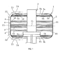
- a tire vulcanization bladder 1 (hereafter referred to as bladder 1) as illustrated in FIGS. 1 to 3 is made from rubber such as butyl rubber, formed into a cylindrical shape.
- the thickness Gb of a bladder main body portion 2 is a predetermined constant thickness, and at the two end portions in the cylinder axial direction (opening end portions), a top side clamp portion 3a and a bottom side clamp portion 3b are provided that are formed thicker than the thickness Gb of the bladder main body portion 2.
- the thickness Gb varies depending on the size of the tire, but for example is about 4 mm to 20 mm. Note that the "constant" in the constant thickness of the thickness Gb includes for a certain percentage of variation that normally occurs in bladders.
- the bladder 1 is installed in a central mechanism 7 of a vulcanization device with the cylinder axial direction in the vertical direction. Specifically, the top side clamp portion 3a and the bottom side clamp portion 3b of the bladder 1 are retained by a disc-shaped top side retaining portion 8a and a bottom side retaining portion 8b installed on the center post of the central mechanism 7.
- An injection nozzle 9a for injecting a heating medium H (and pressurizing medium), such as steam, inside the bladder 1 is provided on the center post of the central mechanism 7.
- Rubber circular ribs 4A extending in the circumferential direction are formed in the portion of the inner surface of the bladder 1 corresponding to the tread portion Z1 of the tire being manufactured, and rubber circular grooves 5A extending in the circumferential direction are formed in the portions corresponding to the shoulder portions Z2 and the bead portions Z4 of the tire being manufactured.
- the circular ribs 4A are ribs that make a full circle in the circumferential direction on the inner surface of the bladder 1, and the multiple circular ribs 4A are formed at predetermined disposal spacing Pr.
- the circular grooves 5A are grooves that make a full circle in the circumferential direction on the inner surface of the bladder 1, and multiple circular grooves 5A are formed at predetermined disposal spacing Pg.
- the cross-sectional shape of the circular ribs 4A in this embodiment has a peaked shape tapering towards the top portion 4a, but various types of shape can be adopted, and other aspects of the specification can be changed as appropriate.
- the circular grooves 5A with the same specification (same shape, groove depth D, and groove width Wg) are provided at a constant disposal spacing Pg, but the specification can be changed as appropriate.
- At least one of rubber ribs and grooves extending in the circumferential direction are formed in the portions on the inner surface of the bladder 1 corresponding to the tread portion Z1, the shoulder portions Z2, and the bead portions Z4 of the tire.
- the portion on the inner surface of the bladder 1 corresponding to the side portion Z3 of the tire has a flat shape where neither ribs nor grooves are formed.
- Ribs are formed integrally with the bladder main body portion 2 with the rubber from which the bladder main body portion 2 is configured, and grooves are formed integrally with the bladder main body portion 2 by recessing the rubber configuring the bladder main body portion 2.
- ribs are not formed in at least the portion on the inner surface of the bladder 1 corresponding to the main grooves g of the tire, from among the portion corresponding to the tread portion Z1 of the tire.
- helical ribs 4B in which multiple circumferential ribs are connected in a helix can be adopted as the ribs.
- helical grooves 5B in which multiple circumferential grooves are connected in a helix can be adopted as the grooves.
- the shoulder portions Z2 of the tire being manufactured is the location with the greatest curvature (small radius of curvature) of all the locations.
- the bead portion Z4 is a location with the opposite curvature direction to the other locations.
- a cross-sectional area and the disposal spacing Pr of the circular ribs 4A can also be set constant, but by varying at least one of the cross-sectional area and the disposal spacing Pr of the circular ribs 4A, it is possible to set circumferential stiffness of the bladder 1 in the center portion in the vertical direction of the bladder to be the maximum towards the center CL in the vertical direction of the bladder 1.
- the circular ribs 4A are not formed on the portion of the inner surface of the bladder 1 corresponding to the main grooves g of the tire, then by varying at least one of the cross-sectional area and the spacing in the vertical direction of the circular ribs 4A excluding the portion on the inner surface of the bladder 1 corresponding to the main grooves g of the tire, circumferential stiffness of the bladder 1 in the center portion in the vertical direction of the bladder is set to be the maximum towards the center in the vertical direction.
- the disposal spacing Pr of the circular ribs 4A is constant and the cross-sectional area is varied.
- the rib heights become larger in the order H3, H2, and H1 towards the center CL in the vertical direction.
- the width Wr of the root portion 4b of each of the circular ribs 4A is the same, the cross-sectional area of the circular ribs 4A is set to be the maximum towards the center CL in the vertical direction of the bladder 1.
- circumferential stiffness of the bladder 1 increases gradually by a maximum of about 40% to 60% towards the center CL in the vertical direction.
- the center portion in the vertical direction of the bladder is the range of about 5% to 20% of the length in the vertical direction of the bladder 1 (the length from the top side clamp portion 3a to the bottom side clamp portion 3b) on either side in the vertical direction from the center CL in the vertical direction of the bladder 1.
- a green tire G that is set in the horizontal state within a mold 10 installed in a vulcanization device 6 is vulcanized using the bladder 1, as illustrated in FIG. 4 .
- the mold 10 is configured from a top side mold 10a, a bottom side mold 10b, a circular upper portion plate 10c, and a circular lower portion plate 10d.
- the green tire G is arranged within the opened mold 10, and the bladder 1 is inserted into the green tire G.
- the mold 10 is closed, and the heating medium H (and pressurizing medium) is injected into the bladder 1 from the injection nozzle 9a, thereby filling the mold 10.
- the heating medium H and pressurizing medium
- the inner surface of the green tire G is heated while applying pressure by expanding the bladder 1 using a gas such as steam, air, nitrogen, or the like.
- the bladder 1 is expanded as illustrated in FIG. 4 , the bladder 1 is further expanded to apply pressure to the whole inner surface of the green tire G to vulcanize the green tire G, as illustrated in FIGS. 5 and 6 .
- circumferential stiffness of the portion corresponding to the tread portion Z1 is greater than that of other portions. Therefore, when the bladder 1 is expanded, it is possible to prevent the portion corresponding to the tread portion Z1 from expanding excessively and strongly applying pressure more than necessary to the green tire G.
- the multiple circular ribs 4A (the helical ribs 4B in which multiple circumferential ribs are connected in a helix)
- the variation in vertical stiffness of the portions where the ribs are formed is comparatively small.
- the multiple circular grooves 5A (the helical grooves 5B in which multiple circumferential grooves are connected in a helix)
- the change in circumferential stiffness of the portions where the grooves are formed is comparatively small. Accordingly, by forming the ribs or grooves on the inner surface of the bladder 1 in this way, stiffness in the desired direction of the bladder 1 can be freely changed. In other words, the degree of freedom of design of the bladder 1 is increased significantly. In this way, it is possible to apply the appropriate pressure to the green tire G by the bladder 1 in accordance with the inner surface shape of each of the parts of the tire being manufactured.
- the thickness Gb of the bladder main body portion 2 is a constant thickness, so it is possible to minimize changes in the thermal conductance. Therefore, it is possible to manufacture a high quality pneumatic tire.
- the green tire G is pressed against main groove forming protrusions 11 of the mold 10, so local expansion to the inner side can easily occur. Therefore, ribs may be not provided on the inner surface of the bladder 1 at the portions corresponding to the main grooves g, as in this embodiment, so that a flat shape is obtained. In this way, these portions of the bladder 1 can more easily expand outward, so the local expansion to the inner side of the green tire G can be reduced.
- each of the circular ribs 4A is kept constant and varying the disposal spacing Pr of the circular ribs 4A, it is possible to set circumferential stiffness of the bladder 1 in the center portion in the vertical direction of the bladder to be the maximum towards the center CL in the vertical direction.
- the circular ribs 4A in FIG. 7 are all the same (the same shape with the same rib height H and width Wr at the root portion 4b), and the disposal spacings Pr of adjacent circular ribs 4A becomes smaller in the order Pr3, Pr2, Pr1 towards the center CL in the vertical direction.
- the cross-sectional shape of the circular ribs 4A can also be an undercut shape in which the top portion 4a is wider than the root portion 4b.
- the top portion 4a has a circular shape.
- the height H of the circular ribs 4A is not greater than the thickness Gb of the bladder main body portion 2, for example from 50% to 100% of the thickness Gb.
- the disposal spacing Pr of the circular ribs 4A is not less than 0.5 and not greater than 2.0 (from 50% to 200%) of the thickness Gb of the bladder main body portion 2.
- the cross-sectional area of the bladder 1 over the range that the circular ribs 4A are provided should be about from 130% to 160% of the cross-sectional area in the case where the circular ribs 4A are not provided (in other words, where the thickness Gb is constant).
- the height H of the circular ribs 4A is less than 50% of the thickness Gb or if the disposal spacing Pr exceeds 2.0 of the thickness Gb, the increase in circumferential stiffness of the bladder 1 could be too small. If the height H of the circular ribs 4A exceeds 100% of the thickness Gb or if the disposal spacing Pr is less than 0.5 of the thickness Gb, the increase in circumferential stiffness of the bladder 1 could be too great, which creates difficulties in terms of manufacture (including increasing cost), and the difference in thermal conductance with other portions could be too great.
- the helical ribs 4B in which multiple circumferential ribs are connected in a helix at the predetermined disposal spacing Pr can be used, as in the embodiment illustrated in FIG. 9 .
- the helical ribs 4B in which multiple circumferential ribs are connected in a helix at the predetermined disposal spacing Pg can be used.
- the disposal spacings Pr and Pg are the spacing between adjacent portions with one revolution. Virtually the same effect as the previous embodiment can be obtained with this embodiment.
- the heating medium H (and pressurizing medium) is injected and filled into the bladder 1 from the injection nozzle 9a in the vulcanization process, the heating medium H flows along the helical ribs 4B and the helical grooves 5B, and this is expected to have the merit that the heating medium H can be easily agitated within the bladder 1.
- the inclination directions of the helical ribs 4B and the helical grooves 5B are different, with the helical ribs 4B having a positive slope and the helical grooves 5B having a negative slope, but the helical ribs 4B and the helical grooves 5B can have the same inclination direction. Also, the same specification and the same arrangement can be applied to the helical ribs 4B and the helical grooves 5B as the circular ribs 4A and the circular grooves 5A as described in the previous embodiment.
Landscapes
- Engineering & Computer Science (AREA)
- Mechanical Engineering (AREA)
- Moulds For Moulding Plastics Or The Like (AREA)
- Heating, Cooling, Or Curing Plastics Or The Like In General (AREA)
Abstract
Description
- The present invention relates to a tire vulcanization bladder and a pneumatic tire manufacturing method, and more particularly relates to a tire vulcanization bladder and a pneumatic tire manufacturing method using the tire vulcanization bladder capable of applying the appropriate pressure to a green tire in accordance with the inner surface shape of each part of the tire being manufactured.
- When manufacturing pneumatic tires, a green tire is set in a mold, then a vulcanization bladder is expanded inside the green tire and vulcanization is carried out. The green tire is normally set within the mold in a horizontal state, and the vulcanization bladder is arranged with the cylinder axial direction in the vertical direction. The cylindrical vulcanization bladder normally has a constant thickness (circumferential stiffness is constant in the vertical direction), and top and bottom ends of the bladder are fixed with clamp members and inflated, so the center portion in the vertical direction expands most, and applies a stronger pressure than other parts.
- Also, in recent years the trend towards low aspect ratio tires has progressed with higher performance tires, so the curvature of the inner surface in the tire cross-section varies greatly depending on the position. This curvature affects the pressure applied by the expanded vulcanization bladder to the green tire. The pressure applied by the vulcanization bladder to the portions corresponding to the locations on the inner surface of the cross-section of the tire being manufactured where the curvature is large tends to be smaller than the pressure at the portions corresponding to the locations where the curvature is small. As a result, when pressure is applied to the green tire by the vulcanization bladder, the unvulcanized rubber moves from the portions where the applied pressure is large towards the portions where it is small, which produces the problem that the rubber thickness of the manufactured tire is not same as the setting.
- For example, it has been proposed that a bladder cap part be configured from a reinforcement reduction member formed from organic fibers or the like (see Patent Document 1). Also, it has been proposed that a reinforcing layer be disposed in a specific portion only of the inner surface of the vulcanization bladder, to increase stiffness of the portion where the reinforcing layer has been provided (see Patent Document 2). However, stiffness in the portions where the reinforcement reduction member or the reinforcing layer are provided is increased in all directions, not just circumferential stiffness, so it is difficult to apply the appropriate pressure in accordance with the inner surface shape of each location of the tire being manufactured.
-
- Patent Document 1: Japanese Unexamined Patent Application Publication No.
2006-103123A - Patent Document 2: Japanese Unexamined Patent Application Publication No.
2008-126495A - It is an object of the present invention to provide the tire vulcanization bladder and the pneumatic tire manufacturing method using the tire vulcanization bladder capable of applying the appropriate pressure in accordance with the inner surface shape of each part of the tire being manufactured.
- A tire vulcanization bladder according to the present invention to achieve the above object is the tire vulcanization bladder used when vulcanizing a green tire set in a horizontal state within a mold, the bladder comprising a cylindrical bladder main body portion having a thickness thereof set to a constant thickness, at least one of rubber ribs and grooves extending in the circumferential direction formed on the inner surface of the bladder at the portions corresponding to the tread portion, the shoulder portions, and the bead portions of the tire; the ribs being multiple circular ribs or helical ribs in which multiple circumferential ribs are connected in a helix, and the grooves being multiple circular grooves or helical grooves in which multiple circumferential grooves are connected in a helix.
- Also, the method of manufacturing a pneumatic tire according to the present invention includes vulcanizing a green tire using the tire vulcanization bladder as described above.
- According to the present invention, the thickness of the cylindrical bladder main body portion is set to a constant thickness, and at least one of rubber ribs and grooves extending in the circumferential direction is formed on the inner surface of the bladder corresponding to the tread portion, the shoulder portions, and the bead portions of the tire, so circumferential stiffness of the portion where the ribs are formed is increased, and vertical stiffness (cylinder axial direction) of the portions where the grooves are formed is reduced. Also, with multiple circular ribs or helical ribs in which multiple circumferential ribs are connected in a helix, the change in vertical stiffness of the portions where the ribs are formed is comparatively small. On the other hand, with the multiple circular grooves or helical grooves in which multiple circumferential grooves are connected in a helix, the change in circumferential stiffness of the portions where the grooves are formed is comparatively small. Accordingly, by forming the ribs or grooves on the inner surface of the vulcanization bladder, stiffness in the desired direction of the vulcanization bladder can be freely changed. Therefore, it is possible to apply the appropriate pressure to the green tire by the vulcanization bladder in accordance with the inner surface shape of each of the parts of the tire being manufactured. Associated with this, it is possible to reduce movement of the unvulcanized rubber of the green tire in unwanted directions during vulcanization when the pressure is applied to the green tire by the vulcanization bladder, which has the advantage that the rubber thickness of the vulcanized tire is the same as the setting.
- Here, for example, a specification in which the ribs are formed in the portion of the inner surface of the bladder corresponding to the tread portion of the tire, and the grooves are formed in the portions of the inner surface of the bladder corresponding to the shoulder portions and the bead portions of the tire can be adopted. With this specification, it is possible to prevent the portion of the vulcanization bladder corresponding to the tread portion from being excessively expanded and applying more than the necessary pressure to the green tire, while preventing the amount of expansion of the portion of the bladder corresponding to the shoulder portions and the bead portions from being too small and the pressure applied to the green tire from being weaker than necessary.
- A specification can be adopted in which the ribs are not formed in the portions corresponding to main grooves of the tire of the portion of the inner surface of the bladder corresponding to the tread portion of the tire. At the portions corresponding to the main grooves, the green tire is pressed against main groove forming protrusions of the mold, so local expansion to the inner side can easily occur. Therefore, by not providing ribs on the inner surface of the vulcanization bladder corresponding to these portions, these portions of the vulcanization bladder can more easily expand outward, so it is possible to reduce the local expansion to the inner side of the green tire.
- A specification can be adopted in which circumferential stiffness of the bladder in the center portion in the vertical direction of the bladder is set to be the maximum towards the center in the vertical direction by varying at least one of a cross-sectional area and a disposal spacing of the rib. If ribs are not formed on the portions of the inner surface of the bladder corresponding to the main grooves of the tire, a specification can be adopted in which circumferential stiffness of the bladder in the center portion in the vertical direction of the bladder excluding the portions of the inner surface of the bladder corresponding to the main grooves of the tire can be set to be the maximum towards the center in the vertical direction, by the same means. With this specification, when the vulcanization bladder is expanded, the center portion in the vertical direction of the bladder which expands most easily expands more easily in a flat manner. More preferably, a specification can be adopted in which circumferential stiffness of the bladder in the center portion in the vertical direction of the bladder is vertically symmetrical with respect to the center in the vertical direction of the bladder.
- A specification can be adopted in which the cross-sectional shape of the ribs is an undercut shape in which the top portion is wider than the root portion. With this specification, it is possible to greatly increase circumferential stiffness, by reducing the increase in vertical stiffness of the bladder.
- In order to apply the appropriate pressure in accordance with the inner surface shape of each part of the tire being manufactured, while minimizing the effect of the thermal conductance produced by providing the ribs and grooves on the inner surface of the bladder, for example, the height of the ribs may be not greater than the thickness of the bladder main body portion, and the disposal spacing of the ribs may be not less than 0.5 to not greater than 2.0 of the thickness of the bladder main body portion. Also, the depth of the grooves may be not less than 0.3 to not greater than 0.5 of the thickness of the bladder main body portion, and the disposal spacing of the grooves may be not less than 0.5 to not greater than 2.0 of the minimum thickness calculated by subtracting the depth of the groove from the thickness of the bladder main body portion.
-
- FIG. 1
- is an explanatory view illustrating a vertical cross-section through an embodiment of a tire vulcanization bladder according to the present invention.
- FIG. 2
- is an enlarged view around ribs of
FIG. 1 . - FIG. 3
- is an enlarged view around grooves of
FIG. 1 . - FIG. 4
- is an explanatory view illustrating a half vertical cross-section of the tire vulcanization bladder of
FIG. 1 in an expanded state. - FIG. 5
- is an explanatory view illustrating a half vertical cross-section of the tire vulcanization bladder of
FIG. 4 in a state where it is abutting the whole inner surface of a green tire. - FIG. 6
- is an enlarged view of a portion of
FIG. 5 . - FIG. 7
- is a cross-sectional view illustrating ribs arranged with a disposal spacing varied.
- FIG. 8
- is a cross-sectional view illustrating a modified example of ribs.
- FIG. 9
- is an explanatory view illustrating a vertical cross-section through another embodiment of the tire vulcanization bladder according to the present invention.
- The following is a description of the tire vulcanization bladder and a pneumatic tire manufacturing method according to the present embodiment based on the embodiments illustrated on the drawings.
- A tire vulcanization bladder 1 (hereafter referred to as bladder 1) as illustrated in
FIGS. 1 to 3 is made from rubber such as butyl rubber, formed into a cylindrical shape. The thickness Gb of a bladdermain body portion 2 is a predetermined constant thickness, and at the two end portions in the cylinder axial direction (opening end portions), a topside clamp portion 3a and a bottomside clamp portion 3b are provided that are formed thicker than the thickness Gb of the bladdermain body portion 2. The thickness Gb varies depending on the size of the tire, but for example is about 4 mm to 20 mm. Note that the "constant" in the constant thickness of the thickness Gb includes for a certain percentage of variation that normally occurs in bladders. - The
bladder 1 is installed in acentral mechanism 7 of a vulcanization device with the cylinder axial direction in the vertical direction. Specifically, the topside clamp portion 3a and the bottomside clamp portion 3b of thebladder 1 are retained by a disc-shaped topside retaining portion 8a and a bottomside retaining portion 8b installed on the center post of thecentral mechanism 7. Aninjection nozzle 9a for injecting a heating medium H (and pressurizing medium), such as steam, inside thebladder 1 is provided on the center post of thecentral mechanism 7. - Rubber
circular ribs 4A extending in the circumferential direction are formed in the portion of the inner surface of thebladder 1 corresponding to the tread portion Z1 of the tire being manufactured, and rubbercircular grooves 5A extending in the circumferential direction are formed in the portions corresponding to the shoulder portions Z2 and the bead portions Z4 of the tire being manufactured. Thecircular ribs 4A are ribs that make a full circle in the circumferential direction on the inner surface of thebladder 1, and the multiplecircular ribs 4A are formed at predetermined disposal spacing Pr. Thecircular grooves 5A are grooves that make a full circle in the circumferential direction on the inner surface of thebladder 1, and multiplecircular grooves 5A are formed at predetermined disposal spacing Pg. - The cross-sectional shape of the
circular ribs 4A in this embodiment has a peaked shape tapering towards thetop portion 4a, but various types of shape can be adopted, and other aspects of the specification can be changed as appropriate. Thecircular grooves 5A with the same specification (same shape, groove depth D, and groove width Wg) are provided at a constant disposal spacing Pg, but the specification can be changed as appropriate. - In the present invention, at least one of rubber ribs and grooves extending in the circumferential direction are formed in the portions on the inner surface of the
bladder 1 corresponding to the tread portion Z1, the shoulder portions Z2, and the bead portions Z4 of the tire. The portion on the inner surface of thebladder 1 corresponding to the side portion Z3 of the tire has a flat shape where neither ribs nor grooves are formed. Ribs are formed integrally with the bladdermain body portion 2 with the rubber from which the bladdermain body portion 2 is configured, and grooves are formed integrally with the bladdermain body portion 2 by recessing the rubber configuring the bladdermain body portion 2. In this embodiment, ribs are not formed in at least the portion on the inner surface of thebladder 1 corresponding to the main grooves g of the tire, from among the portion corresponding to the tread portion Z1 of the tire. - As described later,
helical ribs 4B in which multiple circumferential ribs are connected in a helix can be adopted as the ribs. Also,helical grooves 5B in which multiple circumferential grooves are connected in a helix can be adopted as the grooves. - The shoulder portions Z2 of the tire being manufactured is the location with the greatest curvature (small radius of curvature) of all the locations. The bead portion Z4 is a location with the opposite curvature direction to the other locations.
- In the present invention, a cross-sectional area and the disposal spacing Pr of the
circular ribs 4A can also be set constant, but by varying at least one of the cross-sectional area and the disposal spacing Pr of thecircular ribs 4A, it is possible to set circumferential stiffness of thebladder 1 in the center portion in the vertical direction of the bladder to be the maximum towards the center CL in the vertical direction of thebladder 1. However, if thecircular ribs 4A are not formed on the portion of the inner surface of thebladder 1 corresponding to the main grooves g of the tire, then by varying at least one of the cross-sectional area and the spacing in the vertical direction of thecircular ribs 4A excluding the portion on the inner surface of thebladder 1 corresponding to the main grooves g of the tire, circumferential stiffness of thebladder 1 in the center portion in the vertical direction of the bladder is set to be the maximum towards the center in the vertical direction. In this embodiment, the disposal spacing Pr of thecircular ribs 4A is constant and the cross-sectional area is varied. - In other words, in the
circular ribs 4A ofFIG. 2 , the rib heights become larger in the order H3, H2, and H1 towards the center CL in the vertical direction. Because the width Wr of theroot portion 4b of each of thecircular ribs 4A is the same, the cross-sectional area of thecircular ribs 4A is set to be the maximum towards the center CL in the vertical direction of thebladder 1. In the range that thecircular ribs 4A is formed, circumferential stiffness of thebladder 1 increases gradually by a maximum of about 40% to 60% towards the center CL in the vertical direction. - The center portion in the vertical direction of the bladder is the range of about 5% to 20% of the length in the vertical direction of the bladder 1 (the length from the top
side clamp portion 3a to the bottomside clamp portion 3b) on either side in the vertical direction from the center CL in the vertical direction of thebladder 1. - In the manufacturing method of the pneumatic tire according to the present invention, a green tire G that is set in the horizontal state within a
mold 10 installed in avulcanization device 6 is vulcanized using thebladder 1, as illustrated inFIG. 4 . In this embodiment, themold 10 is configured from atop side mold 10a, abottom side mold 10b, a circularupper portion plate 10c, and a circularlower portion plate 10d. The green tire G is arranged within the openedmold 10, and thebladder 1 is inserted into the green tire G. - Next, the
mold 10 is closed, and the heating medium H (and pressurizing medium) is injected into thebladder 1 from theinjection nozzle 9a, thereby filling themold 10. Specifically the inner surface of the green tire G is heated while applying pressure by expanding thebladder 1 using a gas such as steam, air, nitrogen, or the like. - After the
bladder 1 is expanded as illustrated inFIG. 4 , thebladder 1 is further expanded to apply pressure to the whole inner surface of the green tire G to vulcanize the green tire G, as illustrated inFIGS. 5 and6 . As a result of forming the multiplecircular ribs 4A on the inner surface of thebladder 1, circumferential stiffness of the portion corresponding to the tread portion Z1 is greater than that of other portions. Therefore, when thebladder 1 is expanded, it is possible to prevent the portion corresponding to the tread portion Z1 from expanding excessively and strongly applying pressure more than necessary to the green tire G. - On the other hand, as a result of the multiple
circular grooves 5A formed on the inner surface of thebladder 1, vertical stiffness of the portions corresponding to the shoulder portions Z2 and the bead portions Z4 is smaller than that of the other portions. In this way, at the portions corresponding to the shoulder portions Z2 and the bead portions Z4, thebladder 1 deforms easily to follow the inner surface shape of the cross-section of the tire to be manufactured, even without applying high inner pressure. Therefore, when thebladder 1 is expanded, it is possible to prevent the problem that the amount of expansion at the portions corresponding to the shoulder portions Z2 and the bead portions Z4 is small and the pressure applied to the green tire G is weaker than necessary. In other words, it is possible to apply more pressure than conventionally to the portions corresponding to the shoulder portions Z2 and the bead portions Z4 of the green tire G, which were difficult to strongly apply pressure to with thebladder 1. - Also, with the multiple
circular ribs 4A (thehelical ribs 4B in which multiple circumferential ribs are connected in a helix), the variation in vertical stiffness of the portions where the ribs are formed is comparatively small. On the other hand, with the multiplecircular grooves 5A (thehelical grooves 5B in which multiple circumferential grooves are connected in a helix), the change in circumferential stiffness of the portions where the grooves are formed is comparatively small. Accordingly, by forming the ribs or grooves on the inner surface of thebladder 1 in this way, stiffness in the desired direction of thebladder 1 can be freely changed. In other words, the degree of freedom of design of thebladder 1 is increased significantly. In this way, it is possible to apply the appropriate pressure to the green tire G by thebladder 1 in accordance with the inner surface shape of each of the parts of the tire being manufactured. - Associated with this, it is possible to reduce movement of the unvulcanized rubber of the green tire G in unwanted directions during vulcanization, which has the advantage that the rubber thickness of the vulcanized tire is the same as the setting. Also, the thickness Gb of the bladder
main body portion 2 is a constant thickness, so it is possible to minimize changes in the thermal conductance. Therefore, it is possible to manufacture a high quality pneumatic tire. - At the portions corresponding to the main grooves g of the tire, the green tire G is pressed against main
groove forming protrusions 11 of themold 10, so local expansion to the inner side can easily occur. Therefore, ribs may be not provided on the inner surface of thebladder 1 at the portions corresponding to the main grooves g, as in this embodiment, so that a flat shape is obtained. In this way, these portions of thebladder 1 can more easily expand outward, so the local expansion to the inner side of the green tire G can be reduced. - Also, when the
bladder 1 is expanded, the amount of expansion is the greatest near the center CL in the vertical direction, so a specification may be adopted in which circumferential stiffness of thebladder 1 is set to be the maximum towards the center CL in the vertical direction, as in this embodiment. With this specification, the center portion in the vertical direction of the bladder can more easily expand in a flat manner, and it is possible to make the pressure applied by the expandedbladder 1 to the inner surface of the green tire G at the center portion in the vertical direction of the bladder generally constant. More preferable is a specification in which circumferential stiffness of thebladder 1 is symmetrical in the vertical direction with respect to the center CL in the vertical direction. - For example, as illustrated in
FIG. 7 , by keeping the cross-sectional area of each of thecircular ribs 4A constant and varying the disposal spacing Pr of thecircular ribs 4A, it is possible to set circumferential stiffness of thebladder 1 in the center portion in the vertical direction of the bladder to be the maximum towards the center CL in the vertical direction. Thecircular ribs 4A inFIG. 7 are all the same (the same shape with the same rib height H and width Wr at theroot portion 4b), and the disposal spacings Pr of adjacentcircular ribs 4A becomes smaller in the order Pr3, Pr2, Pr1 towards the center CL in the vertical direction. - Alternatively, by varying both the cross-sectional area of the
circular ribs 4A and the disposal spacing Pr of thecircular ribs 4A, it is possible to set circumferential stiffness of thebladder 1 to be the maximum towards the center CL in the vertical direction. - As illustrated in
FIG. 8 , the cross-sectional shape of thecircular ribs 4A can also be an undercut shape in which thetop portion 4a is wider than theroot portion 4b. In this embodiment, thetop portion 4a has a circular shape. By providing the undercut shape in this manner, the increase in vertical stiffness is easily reduced while increasing circumferential stiffness of thebladder 1. - In
FIG. 8 , the disposal spacing Pr of thecircular ribs 4A is constant, the widths Wr of theroot portions 4b are the same, and the rib height H of thecircular ribs 4A increases in the order H3, H2, H1 towards the center CL in the vertical direction. In other words, by making the disposal spacing Pr of thecircular ribs 4A constant and varying the cross-sectional area of thecircular ribs 4A, circumferential stiffness of thebladder 1 in the center portion in the vertical direction of the bladder is set to be the maximum towards the center CL in the vertical direction. - Preferably the height H of the
circular ribs 4A is not greater than the thickness Gb of the bladdermain body portion 2, for example from 50% to 100% of the thickness Gb. Also, preferably the disposal spacing Pr of thecircular ribs 4A is not less than 0.5 and not greater than 2.0 (from 50% to 200%) of the thickness Gb of the bladdermain body portion 2. In addition, the cross-sectional area of thebladder 1 over the range that thecircular ribs 4A are provided should be about from 130% to 160% of the cross-sectional area in the case where thecircular ribs 4A are not provided (in other words, where the thickness Gb is constant). - If the height H of the
circular ribs 4A is less than 50% of the thickness Gb or if the disposal spacing Pr exceeds 2.0 of the thickness Gb, the increase in circumferential stiffness of thebladder 1 could be too small. If the height H of thecircular ribs 4A exceeds 100% of the thickness Gb or if the disposal spacing Pr is less than 0.5 of the thickness Gb, the increase in circumferential stiffness of thebladder 1 could be too great, which creates difficulties in terms of manufacture (including increasing cost), and the difference in thermal conductance with other portions could be too great. - Preferably the depth D of the
circular grooves 5A is, for example, not less than 0.3 and not greater than 0.5 (from 30% to 50%) of the thickness Gb of the bladdermain body portion 2. Preferably the disposal spacing Pg of thecircular grooves 5A is not less than 0.5 and not greater than 2.0 (from 50% to 200%) of the minimum thickness calculated by subtracting the depth D of thecircular grooves 5A from the thickness Gb of the bladdermain body portion 2. In addition, the cross-sectional area of thebladder 1 over the range where thecircular grooves 5A are provided should be not less than 70% of the cross-sectional area in the case that thecircular grooves 5A are not provided (in other words, when the thickness Gb is constant). - If the depth D of the
circular grooves 5A is less than 0.3 of the thickness Gb or if the disposal spacing Pg is greater than 2.0 of the minimum thickness calculated by subtracting the depth D of thecircular grooves 5A from the thickness Gb of the bladdermain body portion 2, the reduction in vertical stiffness of thebladder 1 could be too small. If the depth D of thecircular grooves 5A exceeds 0.5 of the thickness Gb of the bladdermain body portion 2 or if the disposal spacing Pg is less than 0.5 of the minimum thickness calculated by subtracting the depth D of thecircular grooves 5A from the thickness Gb of the bladdermain body portion 2, the reduction in vertical stiffness of thebladder 1 could be too great, which would produce difficulties in terms of manufacture (including increased cost), and the difference of thermal conductance from the other portions could be too large. Various shapes can be adopted for the cross-sectional shape of thecircular grooves 5A, but preferably the bottom surface has a circular arc shaped as in the embodiments described above, from the point of view of durability and the like. - Instead of the
circular ribs 4A as described above, thehelical ribs 4B in which multiple circumferential ribs are connected in a helix at the predetermined disposal spacing Pr can be used, as in the embodiment illustrated inFIG. 9 . Also, instead of thecircular grooves 5A as described above, thehelical ribs 4B in which multiple circumferential ribs are connected in a helix at the predetermined disposal spacing Pg can be used. In the case of a helical shape, the disposal spacings Pr and Pg are the spacing between adjacent portions with one revolution. Virtually the same effect as the previous embodiment can be obtained with this embodiment. - In addition, if the
helical ribs 4B and thehelical grooves 5B are provided in this way, when the heating medium H (and pressurizing medium) is injected and filled into thebladder 1 from theinjection nozzle 9a in the vulcanization process, the heating medium H flows along thehelical ribs 4B and thehelical grooves 5B, and this is expected to have the merit that the heating medium H can be easily agitated within thebladder 1. - In this embodiment, the inclination directions of the
helical ribs 4B and thehelical grooves 5B are different, with thehelical ribs 4B having a positive slope and thehelical grooves 5B having a negative slope, but thehelical ribs 4B and thehelical grooves 5B can have the same inclination direction. Also, the same specification and the same arrangement can be applied to thehelical ribs 4B and thehelical grooves 5B as thecircular ribs 4A and thecircular grooves 5A as described in the previous embodiment. - With the spread of low aspect tires, the present invention is more effective when applied to the manufacture of tires with a low aspect ratio in which there are large differences in curvature of the inner surface of the tire cross-section with location. For example, it is ideal for the manufacture of tires with an aspect ratio of 60% or less.
-
- 1 Bladder
- 2 Bladder main body portion
- 3a Top side clamp portion
- 3b Bottom side clamp portion
- 4A Circular rib
- 4B Helical rib
- 4a Top portion
- 4b Root portion
- 5A Circular groove
- 5B Helical groove
- 6 Vulcanization device
- 7 Central mechanism
- 8a Top side retaining portion
- 8b Bottom side retaining portion
- 9a Injection nozzle
- 10, 10a, 10b, 10c, 10d Mold
- 11 Main groove forming protrusion
- G Green tire
- g Main groove
- Z1 Tread portion
- Z2 Shoulder portion
- Z3 Side portion
- Z4 Bead portion
- H Heating medium
Claims (10)
- A tire vulcanization bladder used upon vulcanizing a green tire set in a horizontal state within a mold, the bladder comprising:a cylindrical bladder main body portion having a thickness thereof set to a constant thickness; andat least one of rubber ribs and grooves extending in a circumferential direction formed on an inner surface of the bladder at portions corresponding to a tread portion, shoulder portions, and bead portions of the tire;the ribs being multiple circular ribs or helical ribs in which multiple circumferential ribs are connected in a helix; and
the grooves being multiple circular grooves or helical grooves in which multiple circumferential grooves are connected in a helix. - The tire vulcanization bladder according to claim 1, wherein
the ribs are formed in the portion of the inner surface of the bladder corresponding to the tread portion of the tire, and the grooves are formed in the portions of the inner surface of the bladder corresponding to the shoulder portions and the bead portions of the tire. - The tire vulcanization bladder according to claim 2, wherein
the ribs are not formed in portions corresponding to main grooves of the tire of the portion of the inner surface of the bladder corresponding to the tread portion of the tire. - The tire vulcanization bladder according to claim 2, wherein
circumferential stiffness of the bladder in a center portion in a vertical direction of the bladder is set to be the maximum towards a center in a vertical direction by varying at least one of a cross-sectional area and a disposal spacing of the rib. - The tire vulcanization bladder according to claim 3, wherein
circumferential stiffness of the bladder in the center portion in the vertical direction of the bladder excluding the portions corresponding to the main grooves of the tire on the inner surface of the bladder is set to be the maximum towards the center in the vertical direction, by varying at least one of the cross-sectional area and the disposal spacing of the rib. - The tire vulcanization bladder according to claim 4 or 5, wherein
circumferential stiffness of the bladder in the center portion in the vertical direction of the bladder is vertically symmetrical with respect to the center in the vertical direction of the bladder. - The tire vulcanization bladder according to any one of claims 1 to 6, wherein
a cross-sectional shape of the rib is an undercut shape with a top portion wider than a root portion. - The tire vulcanization bladder according to any one of claims 1 to 7, wherein
a height of the ribs is not greater than a thickness of the bladder main body portion, and the disposal spacing of the ribs is not less than 0.5 and not greater than 2.0 of the thickness of the bladder main body portion. - The tire vulcanization bladder according to any one of claims 1 to 8, wherein
a depth of the grooves is not less than 0.3 and not greater than 0.5 of the thickness of the bladder main body portion, and a disposal spacing of the grooves is not less than 0.5 and not greater than 2.0 of the minimum thickness calculated by subtracting the depth of the groove from the thickness of the bladder main body portion. - A method of manufacturing a pneumatic tire, the method comprising the step of: vulcanizing a green tire using the tire vulcanization bladder described in any one of claims 1 to 9.
Applications Claiming Priority (2)
| Application Number | Priority Date | Filing Date | Title |
|---|---|---|---|
| JP2012248643 | 2012-11-12 | ||
| PCT/JP2013/080422 WO2014073678A1 (en) | 2012-11-12 | 2013-11-11 | Tire vulcanization bladder and pneumatic tire manufacturing method |
Publications (2)
| Publication Number | Publication Date |
|---|---|
| EP2930000A1 true EP2930000A1 (en) | 2015-10-14 |
| EP2930000A4 EP2930000A4 (en) | 2016-09-07 |
Family
ID=50684769
Family Applications (1)
| Application Number | Title | Priority Date | Filing Date |
|---|---|---|---|
| EP13853728.7A Withdrawn EP2930000A4 (en) | 2012-11-12 | 2013-11-11 | Tire vulcanization bladder and pneumatic tire manufacturing method |
Country Status (5)
| Country | Link |
|---|---|
| US (1) | US20160214340A1 (en) |
| EP (1) | EP2930000A4 (en) |
| JP (1) | JPWO2014073678A1 (en) |
| CN (1) | CN104755242A (en) |
| WO (1) | WO2014073678A1 (en) |
Cited By (1)
| Publication number | Priority date | Publication date | Assignee | Title |
|---|---|---|---|---|
| EP3156255A4 (en) * | 2014-06-11 | 2017-04-19 | Bridgestone Corporation | Pneumatic tire and mold for vulcanizing tire |
Families Citing this family (2)
| Publication number | Priority date | Publication date | Assignee | Title |
|---|---|---|---|---|
| CN106945319A (en) * | 2017-05-18 | 2017-07-14 | 正新橡胶(中国)有限公司 | A kind of tyre vulcanization gasbag mould |
| CN116619800B (en) * | 2023-07-20 | 2023-10-24 | 山东豪迈机械科技股份有限公司 | A tire vulcanization equipment |
Family Cites Families (13)
| Publication number | Priority date | Publication date | Assignee | Title |
|---|---|---|---|---|
| US2695424A (en) * | 1951-12-17 | 1954-11-30 | Us Rubber Co | Thin walled curing bag |
| US2970344A (en) * | 1958-11-06 | 1961-02-07 | William T Morris | Tire curing bag construction |
| GB938797A (en) * | 1960-06-07 | 1963-10-09 | Macbeth Patents Ltd | Improvements in or relating to the manufacture of vehicle tyres |
| JPS60114711U (en) * | 1983-12-29 | 1985-08-03 | 横浜ゴム株式会社 | Bladder for tire curing |
| JPS61162306A (en) * | 1985-01-10 | 1986-07-23 | Sumitomo Rubber Ind Ltd | Bladder for vulcanization of tire |
| JPH07232331A (en) * | 1994-02-24 | 1995-09-05 | Bridgestone Corp | Tire vulcanizing bladder |
| JP2000006154A (en) * | 1998-06-29 | 2000-01-11 | Bridgestone Corp | Vulcanization mold for pneumatic tire, manufacture of pneumatic tire, and pneumatic tire |
| JP4595243B2 (en) * | 2001-05-18 | 2010-12-08 | 横浜ゴム株式会社 | Manufacturing method of pneumatic radial tire |
| JP2005066879A (en) * | 2003-08-27 | 2005-03-17 | Yokohama Rubber Co Ltd:The | Tire vulcanizing bladder |
| JP4507808B2 (en) | 2004-10-05 | 2010-07-21 | 横浜ゴム株式会社 | Manufacturing method of tire vulcanizing bladder |
| JP2007098873A (en) * | 2005-10-07 | 2007-04-19 | Bridgestone Corp | Tire vulcanizing method and apparatus |
| US20080084007A1 (en) * | 2006-10-05 | 2008-04-10 | Carlisle Intangible Company | Low aspect ratio tire curing bladder |
| JP5050804B2 (en) * | 2007-11-21 | 2012-10-17 | 横浜ゴム株式会社 | Tire vulcanization method |
-
2013
- 2013-11-11 JP JP2014524169A patent/JPWO2014073678A1/en active Pending
- 2013-11-11 CN CN201380056329.3A patent/CN104755242A/en active Pending
- 2013-11-11 US US14/442,398 patent/US20160214340A1/en not_active Abandoned
- 2013-11-11 EP EP13853728.7A patent/EP2930000A4/en not_active Withdrawn
- 2013-11-11 WO PCT/JP2013/080422 patent/WO2014073678A1/en not_active Ceased
Cited By (1)
| Publication number | Priority date | Publication date | Assignee | Title |
|---|---|---|---|---|
| EP3156255A4 (en) * | 2014-06-11 | 2017-04-19 | Bridgestone Corporation | Pneumatic tire and mold for vulcanizing tire |
Also Published As
| Publication number | Publication date |
|---|---|
| JPWO2014073678A1 (en) | 2016-09-08 |
| US20160214340A1 (en) | 2016-07-28 |
| CN104755242A (en) | 2015-07-01 |
| WO2014073678A1 (en) | 2014-05-15 |
| EP2930000A4 (en) | 2016-09-07 |
Similar Documents
| Publication | Publication Date | Title |
|---|---|---|
| CN101161447B (en) | Method for manufacturing pneumatic tire | |
| US20150013863A1 (en) | Tire With Pre-Formed Tread And Method Of Making Same | |
| EP2930000A1 (en) | Tire vulcanization bladder and pneumatic tire manufacturing method | |
| BRPI0917223B1 (en) | method for controlling a molding phase of a green tire annular attachment structure, and green tire molding and curing equipment | |
| JP5389962B2 (en) | Tire manufacturing method | |
| JP2008213289A (en) | Inner mold for manufacturing tire and tire manufacturing method using inner mold | |
| JP6055592B2 (en) | Tire manufacturing method | |
| JP5026900B2 (en) | Vulcanized bladder manufacturing method and vulcanized bladder | |
| JP4604783B2 (en) | Manufacturing method of rigid core for tire vulcanization and pneumatic tire | |
| RU2641131C1 (en) | Hard reinforcement ring and method for tyre curing using it | |
| US7513282B1 (en) | Air bladder for tire liners with vee shaped air chambers | |
| EP2993019B1 (en) | Method for manufacturing tire | |
| KR101425038B1 (en) | multi pressure tire bladder | |
| JP5371231B2 (en) | Tire vulcanization mold | |
| KR102301165B1 (en) | Pneumatic tire | |
| JP5367219B2 (en) | Tire manufacturing method | |
| JP2014019136A (en) | Bladder for tire vulcanization, and production method of pneumatic tire | |
| KR101796466B1 (en) | A bladder for tire vulcanization | |
| KR20170062588A (en) | Bladder for vulcanizing tire | |
| JP2015054408A (en) | Mold for tire vulcanization molding, pneumatic tire produced with the mold for tire vulcanization molding and method of producing the pneumatic tire | |
| KR200196975Y1 (en) | Reinforcement Structure of Tire Vulcanization Brad | |
| JP2017042957A (en) | Pneumatic tire manufacturing method | |
| JP2014019135A (en) | Bladder for tire vulcanization, and production method of pneumatic tire | |
| JP2016083855A (en) | Rigidity strengthening ring and tire vulcanization method using the same | |
| JP2012081659A (en) | Vulcanizing mold and method of manufacturing pneumatic tire |
Legal Events
| Date | Code | Title | Description |
|---|---|---|---|
| PUAI | Public reference made under article 153(3) epc to a published international application that has entered the european phase |
Free format text: ORIGINAL CODE: 0009012 |
|
| 17P | Request for examination filed |
Effective date: 20150611 |
|
| AK | Designated contracting states |
Kind code of ref document: A1 Designated state(s): AL AT BE BG CH CY CZ DE DK EE ES FI FR GB GR HR HU IE IS IT LI LT LU LV MC MK MT NL NO PL PT RO RS SE SI SK SM TR |
|
| AX | Request for extension of the european patent |
Extension state: BA ME |
|
| DAX | Request for extension of the european patent (deleted) | ||
| RA4 | Supplementary search report drawn up and despatched (corrected) |
Effective date: 20160804 |
|
| RIC1 | Information provided on ipc code assigned before grant |
Ipc: B29C 33/02 20060101AFI20160729BHEP Ipc: B29C 35/02 20060101ALI20160729BHEP Ipc: B29D 30/06 20060101ALI20160729BHEP Ipc: B29L 30/00 20060101ALI20160729BHEP |
|
| STAA | Information on the status of an ep patent application or granted ep patent |
Free format text: STATUS: REQUEST FOR EXAMINATION WAS MADE |
|
| STAA | Information on the status of an ep patent application or granted ep patent |
Free format text: STATUS: THE APPLICATION IS DEEMED TO BE WITHDRAWN |
|
| 18D | Application deemed to be withdrawn |
Effective date: 20170303 |