EP2929591B1 - Drehbares transpondersystem - Google Patents
Drehbares transpondersystem Download PDFInfo
- Publication number
- EP2929591B1 EP2929591B1 EP13815166.7A EP13815166A EP2929591B1 EP 2929591 B1 EP2929591 B1 EP 2929591B1 EP 13815166 A EP13815166 A EP 13815166A EP 2929591 B1 EP2929591 B1 EP 2929591B1
- Authority
- EP
- European Patent Office
- Prior art keywords
- antenna
- transponder
- signal
- arrays
- antenna elements
- Prior art date
- Legal status (The legal status is an assumption and is not a legal conclusion. Google has not performed a legal analysis and makes no representation as to the accuracy of the status listed.)
- Active
Links
Images

Classifications
-
- H—ELECTRICITY
- H01—ELECTRIC ELEMENTS
- H01Q—ANTENNAS, i.e. RADIO AERIALS
- H01Q21/00—Antenna arrays or systems
- H01Q21/30—Combinations of separate antenna units operating in different wavebands and connected to a common feeder system
-
- H—ELECTRICITY
- H01—ELECTRIC ELEMENTS
- H01Q—ANTENNAS, i.e. RADIO AERIALS
- H01Q3/00—Arrangements for changing or varying the orientation or the shape of the directional pattern of the waves radiated from an antenna or antenna system
- H01Q3/12—Arrangements for changing or varying the orientation or the shape of the directional pattern of the waves radiated from an antenna or antenna system using mechanical relative movement between primary active elements and secondary devices of antennas or antenna systems
-
- H—ELECTRICITY
- H01—ELECTRIC ELEMENTS
- H01Q—ANTENNAS, i.e. RADIO AERIALS
- H01Q3/00—Arrangements for changing or varying the orientation or the shape of the directional pattern of the waves radiated from an antenna or antenna system
- H01Q3/26—Arrangements for changing or varying the orientation or the shape of the directional pattern of the waves radiated from an antenna or antenna system varying the relative phase or relative amplitude of energisation between two or more active radiating elements; varying the distribution of energy across a radiating aperture
- H01Q3/2605—Array of radiating elements provided with a feedback control over the element weights, e.g. adaptive arrays
- H01Q3/2647—Retrodirective arrays
Definitions
- the invention relates to transponder/repeater devices configured for receiving and transmitting electro-magnetic signals.
- Radio frequency transponders are used in a variety of applications.
- a typical transponder system operates to collect an electromagnetic signal/waveform and transmit a response signal/waveform, being similar to the collected signal or not.
- Some transponders utilize a plurality of antenna elements in order to enable direction transmission of electromagnetic signals/waveforms resulting from phase variations between signal portions transmitted by different antenna elements.
- the Van-Atta type repeater is disclosed in U.S. Patent No. 2,90,8002 .
- the Van-Atta type repeater is a passive electromagnetic device for receiving an incident electromagnetic wave and transmitting the received wave back in the direction from whence it has been received.
- the device includes a linear array of no less than four antennas, and means providing electromagnetic paths of equal length between antennas disposed symmetrically with respect to a geometrical center of said linear array.
- U.S. Patent No. 3,736,592 discloses a method and apparatus for obtaining automatic, selective retrodirective beam formation from a circularly symmetric antenna array.
- This system may be employed in an active or passive manner and accomplishes selective retrodirectivity by manipulation of beam terminals of a multiple beam matrix which in turn controls a multimodal network.
- the combination of the two matrix networks provides N separate beams from the circular antenna array.
- control of the reradiated beam pattern is possible.
- This system has the ability to identify the angle of incidence of any particular transmission, and is particularly suited for navigational beacon systems since the reradiated signal can provide bearing information in response to interrogation.
- U.S. Patent No. 4,806,938 Another example of a radio frequency transponder/repeater is disclosed in U.S. Patent No. 4,806,938 .
- an array of receiving antenna elements is coupled to an array of transmitting antenna elements to provide a directional antenna system and including additionally an internal radio frequency source which is also coupled to the array of transmitting antenna elements.
- an internally generated signal provided by the radio frequency source may be transmitted using the transmitting array of the Van Atta System.
- the present invention fulfills the above needs by providing a technique for transponding and/or repeating electromagnetic radiation signals (waveforms) towards a desired direction (i.e. with adjustable angular shift between the received and transmitted signals) while having a relatively simple and robust construction.
- the technique of the present invention may be used to obviate a need for processing the signals to be received and transmitted, and accordingly it may be implemented utilizing relatively simple and robust analogue circuitry and/or by utilizing a simple digital circuitry.
- the transponder of the present invention utilizes two antenna arrays having interconnected antenna elements arranged in a predetermined order, while at least one of the antenna arrays is rotatable with respect to the other to provide a desirably changeable angular shift, including all technical features set out in claim 1.
- transponder of the present invention is capable of operating as a transponder and/or repeater and for clarity will be referred to herein below as a "transponder”.
- transponder referring to the device should be interpreted as referring to the repeater as well, and also describes retrorepeater and directional repeater systems.
- the transponder of the present invention comprises a plurality of antenna elements arranged in first and second antenna arrays (e.g. being respectively receiving and transmitting arrays).
- Each of the antenna elements of the first array is interconnected with an antenna element of the second array, in accordance with the order of said antenna elements in the respective arrays, to form a plurality of receiving-transmitting pairs of antenna elements.
- the receiving-transmitting pairs are configured such that electromagnetic (EM) signals (electromagnetic radiation) collected by one of the antenna elements of the pair (i.e. receiving element) are routed via a connection line to the second antenna element of the pair (i.e. transmitting element) to be transmitted thereby to form a corresponding electromagnetic signal/radiation.
- EM electromagnetic
- an EM waveform collectively received by the receiving array e.g. first array
- the antenna elements of the transmitting array e.g. second array
- a waveform of corresponding characteristics propagation in a desired (e.g. controllable) direction is reconstructed from the radiation transmitted by the antenna elements of the transmitting array (e.g. second array) to form a waveform of corresponding characteristics propagation in a desired (e.g. controllable) direction.
- the antenna elements of the first and second antenna arrays are paired according to a sequential order of the elements in the arrays, to thereby maintain phase profile (phase variations) of the collected EM signal, associated with the signal's direction of propagation, and reconstruct a corresponding phase profile by the transmitting antenna elements (of the receiving-transmitting pairs) collectively generating a corresponding output (transmitted) signal. More specifically, a wavefront of an electromagnetic signal, propagating from a certain direction, is collected by the plurality of antenna elements of the first array (or the second array) while each antenna element collects the signal with a different phase, or at different times.
- connection lines connecting the antenna elements and forming the receiving-transmitting pairs, with substantially similar electrical properties the signal portions that reach the second antenna element of each pair have similar phase differences between antenna elements and thus form a similar phase profile.
- the phase profile generated by signal portions transmitted by antenna elements of the second antenna array, produces a collective wavefront providing a directional output signal which corresponds to the direction of the collected wavefront (signal). It should be noted that the directionality of the collectively transmitted waveform is determined by both the phase relations between the signal portions transmitted by different antenna elements, as well as the geometry and spacing of the antenna elements in the corresponding antenna array.
- the transponder of the present invention is configured such that at least one of the antenna arrays is rotatable about at least one axis with respect to the other antenna array. This enables simple variations of the direction of the collectively transmitted waveform with respect to the collected waveform by varying a relative angle between the orientation of the first and second antenna arrays.
- connection lines, connecting antenna elements of the first and second arrays to form said receiving-transmitting pairs are preferably configured with similar electrical properties, i.e. similar length, electrical impedance (e.g. resistance, inductance and/or capacitance). Additionally, the connection lines may include signal amplifiers configured to operate at a desired frequency range (e.g. radio frequency in the order of 3GHz and/or X-band of about 10 GHz).
- the transponder system includes an EM isolation system configured to prevent cross-talk between antenna elements of the first and second antenna arrays. Specifically, such an EM isolation system may be employed to reduce cross talk when signal amplifiers are used, and to prevent noise enhancement through resonation "feedback loop".
- a transponder system comprising a first and a second antenna array each comprising a plurality of antenna elements arranged in a predetermined geometry.
- the antenna elements of the first antenna array are respectively interconnected with corresponding antenna elements of the second antenna array by respective connection lines forming a plurality of receiving-transmitting pairs of antenna elements.
- the receiving-transmitting pairs are configured to receive an input electro-magnetic signal by one antenna element and transmit a corresponding output signal by its corresponding antenna element, thereby enabling collective collection of signal waveform and transmission of a corresponding output signal waveform.
- At least one of said first and second antenna arrays are rotatable with respect to the other about at least one predetermined rotation axis to thereby enable variation of direction of propagation of the output signal waveform with respect to direction of propagation of the collected signal waveform.
- the connection lines are preferably of substantially similar length and electrical properties.
- the first and second antenna arrays may have substantially similar spacing between their antenna elements.
- each antenna element of the first antenna array is connected to a corresponding antenna element of the second array in accordance with sequential location of the antenna elements within the arrays to form said receiving-transmitting pairs.
- the first and second antenna arrays may be configured with substantially similar geometries and may have one- or two-dimensional geometries.
- the first and second antenna arrays may be closed loop arrays, being circular or polygonal arrays.
- the first and second antenna arrays may be concentric with respect to one another.
- Said at least one rotation axis may comprise an axis intersecting with a plane defined by one or both of the antenna arrays at a center of the closed loop.
- the antenna arrays may be located in parallel planes.
- the first and second antenna arrays may intersect with an axis of rotation of said at least one rotatable antenna array.
- the transponder comprises an actuation module connected to said at least one rotatable antenna array and configured to enable controllable rotation of said rotatable antenna array about said at least one predetermined rotation axis.
- the transponder comprises a control unit connected to the actuation module and configured for receiving data indicative of a desired angular shift between direction of propagation of the output signal wavefront with respect to direction of propagation of the collected signal waveform, and for operating said actuation module to vary a relative angle between said first and second antenna arrays for providing said angular shift.
- the control unit may comprise a wireless communication module configured to receive appropriate control signals indicative of said angular shift, said control unit being responsive to said appropriate control signals to operate said actuation module accordingly, to thereby enable remote variation of said relative angle between said first and second antenna arrays.
- the transponder may comprise a plurality of signal amplifiers respectively associated with said connection lines and configured to amplify signals passing between the associated antenna elements of the corresponding receiving-transmitting pair.
- the plurality of signal amplifiers may be configured to provide substantially similar signal amplification.
- the plurality of antenna elements may comprise antenna elements configured to receive and transmit electromagnetic radiation with two or more different polarization orientations.
- the transponder may comprise an isolation system configured to reduce cross talk between antenna elements of said first and second antenna arrays.
- the transponder may also comprise a plurality of signal amplifiers respectively associated with the connection lines, wherein the isolation system is configured to suppress said cross talk by a factor greater than signal amplification provided by said signal amplifiers.
- the said isolation system may comprise one or more of the following: (a) one or more parasitic antennas; (b) an electromagnetic isolation layer; (c) one or more frequency dividers/multipliers configured to change the frequency of the transmitted signals relative to the frequency of the received signals in accordance with the antenna elements' spacings of said first and second antenna arrays; and (d) one or more filters configured to filter out frequency components associated with the received signals, while transfer frequency components are associated with the transmitted signals in accordance with antenna elements' spacing of said first and second antenna arrays.
- a signal transmission network comprising two or more transponder systems wherein at least one transponder system is configured as described above.
- the two or more transponders may be arranged at certain locations to enable establishment of signal propagation trajectory along the signal transmission network, such a segment of said signal propagation trajectory being defined between two adjacent transponder systems; wherein a control over the angular shift provided by said at least one transponder system enables establishment of a desired signal propagation trajectory along the network.
- the signal transmission network may comprise a controller connectable to said at least one transponder system and configured and operable to utilize data indicative of a desired trajectory for signal transmission along said signal transmission network, determine at least one corresponding angular shift for said at least one transponder system, and communicate operational instructions indicative of said at least one corresponding angular shift to said at least one transponder system respectively, to thereby establish said desired trajectory through the signal transmission network.
- a transponder comprising a plurality of antenna elements comprising antenna elements associated with first and second antenna arrays having predetermined closed-loop geometry and spacing, each antenna element of the first antenna array being connected to a corresponding antenna element of the second antenna array via a connection line to thereby form a plurality of receiving-transmitting pairs of antenna elements.
- At least one of said first and second antenna arrays is rotatable about at least one axis to thereby enable variation of a relative angle between said first and second antenna arrays.
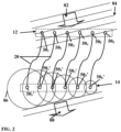
- Fig. 1 schematically illustrating a transponder 10 including first 12 and second 14 antenna arrays, each including a plurality of antenna elements 50 1 -50 n and 50 1 '-50 n ' respectively.
- the antenna elements 50 i of the first antenna array 12 are interconnected via a plurality of connection lines 20 to antenna elements 50 i ' of the second antenna array 14 thereby forming a plurality of receiving-transmitting pairs of antenna elements.
- At least one of the first 12 and second 14 antenna arrays is rotatable about at least one axis with respect to the other array. In the example illustrated in Fig.
- the second antenna array 14 is shown as being rotatable about an axis 24 with respect to the first antenna array 12, however it should be noted that the first antenna array 12 may be rotatable, and in some embodiments, both antenna arrays may be rotatable about the parallel or intersecting axes.
- the receiving-transmitting pairs of antenna elements are configured such that any electromagnetic radiation collected by the receiving antenna element of the pair (e.g. element 50 i of the first antenna array 12 ) is routed (e.g. electrically conveyed and possibly amplified and/or filtered and/or delayed) via the corresponding connection line 20 and transmitted by the other antenna element of the pair (e.g. element 50 i ' of the second antenna array 14 ).
- a waveform collected collectively by the plurality of antenna elements of the first array 12 is conveyed via the connection lines and reconstructed by signal portions transmitted by the antenna elements of the second array 14, and optionally also vice versa.
- orientation of the rotatable antenna array (being the first array, the second array or both) is selected to provide a desired angular shift between collected a electromagnetic waveform and a corresponding collectively transmitted electromagnetic waveform as will be described further below with reference to Fig. 2 .
- connection lines 20 between antenna elements of the first and second antenna arrays may be unidirectional with respect to signal transmission. In some embodiments however both arrays may be configured to receive and transmit EM radiation such that a waveform collected by any one of them is transmitted by the other one.
- the connection lines 20 between antenna elements of the first and second antenna arrays may be bidirectional lines. Therefore the receiving antenna elements may be associated with either the first or second antenna array, or all antenna elements may receive and transmit in accordance with the EM radiation present in their vicinity.
- the connection lines may include signal amplifiers configured to amplify electric signals and to provide amplified repeating/transponding of collected signals.
- the transponder 10 also includes an actuation module 75 configured to controllably rotate the rotatable antenna array (second antenna array 14 in the present example) to select a desired angular shift between the collected waveform and the collectively transmitted waveform.
- the actuation module 75 may be a motor, a piezoelectric actuation module, a manual rotation module or any other type of controllable actuation module configured to controllably rotate the corresponding antenna array.
- the actuation module is configured to keep the rotatable antenna arrays in a fixed angular orientation for most of its operation time and rotate the antenna array when a different angular shift between collected and transmitted signals is desired (e.g. by an operator). In this configuration, only when the angular shift is to be changed, the actuation module operates to rotate the corresponding antenna array to a different angular orientation.
- the transponder 10 includes a control unit 70 connected to the actuation module 75.
- the control unit 70 is configured to receive data indicative of a desired angular shift between the collected waveform and the collectively transmitted waveform and to controllably operate the actuation module 75 to rotate the appropriate antenna array accordingly.
- data indicative of the desired angular shift may be received through a communication module 72 associated with the control unit 70.
- the communication module 72 may be a wired or wireless communication module, or it may include an input interface configured to receive manually input data.
- the control unit 70 may determine an appropriate angular orientation of the rotatable antenna array(s) and operate the actuation module 75 to rotate the antenna array accordingly towards the desired angular shift.
- Fig. 2 illustrates the main principles of operation of the transponder 10 shown in Fig. 1 .
- the transponder 10 includes first 12 and second 14 antenna arrays, each including six antenna elements 50 1 -50 6 and 50 1 '-50 6 ' respectively.
- the antenna elements 50 1 -50 6 and 50 1 '-50 6 ' are interconnected between them by connection lines 20 to form receiving transmitting pairs ( 50 1 -50 1 ', 50 2 -50 2 ' ... 50 6 -50 6 ' ).
- the antenna elements are sequentially connected/paired in direct or reverse sequential order.
- the wavefront 84 of the radiation waveform is received by the antenna elements 50 1 -50 6 and thereby electric signals are generated by those elements in accordance with their location (e.g. the phase, time delay and amplitude of the signals may vary between the antenna elements).
- the electric signals received by antenna elements 50 1 -50 6 are routed, via the respective connection lines 20, to the corresponding antenna elements 50 1 '-50 6 ' and the other end of the receiving-transmitting pairs thereby generating electromagnetic radiation which substantially reproduces the collected waveform (e.g. due to the sequential order of the pairing of the antenna elements of the arrays and similar geometry of the arrays).
- an electromagnetic waveform/signal 82 propagates along a certain direction of propagation and is collected by the first antenna array 12 of the transponder.
- the repeating wavefronts 84 of the signal 82 are collected by different antenna elements with time delay which corresponds to the distance between the antenna elements and the relative angle between the antenna array 12 and the incoming signal 82.
- variation of the relative angular orientation of at least one of the first 12 and second 14 antenna arrays generate a corresponding angular shift between the collected 82 and collectively transmitted 86 electromagnetic signals.
- the first and second antenna arrays preferably have a substantially similar geometry; however the antenna elements of the arrays may form a linear geometry, closed loop geometry, or be arranged in any one- or two-dimensional array.
- a substantially similar geometry of the first and second antenna arrays actually means that relative locations of corresponding antenna elements and ratios between distances from one antenna element to another are similar up to an unavoidable manufacturing error.
- the sizes of the first and second antenna arrays may be different while maintaining geometrical similarity between the arrays.
- the spacing between the antenna elements of the receiving array may be different from the spacing between the antenna elements of the transmitting array.
- appropriate frequency dividers/multipliers are used for adjusting the frequency of the transmitted signals in accordance with that of the received signals. It is noted that the different frequencies employed for receiving and transmission may contribute to isolation between the arrays.
- connection lines 20 may include or be associated with frequency dividers/multipliers which are appropriately configured to maintain coherency of the signals received/transmitted by each of the antenna elements of each of the first and second arrays to enable the coherent reconstruction of a signal which is received by one of the arrays, by the other array although the elements' spacings are different these arrays.
- each antenna array includes six antenna elements 50 1 -50 6 and 50 1 '-50 6 ' arranged in a closed loop polygonal geometry.
- the first antenna array 12 is rotatable with respect to the second antenna array 14 about a predetermined axis 24.
- either one or both of the antenna arrays may be configured to be rotatable about one or more axes to thereby provide flexibility in determining a desired angular shift between collected and collectively transmitted signals.
- connection lines 20 may include signal amplifiers 22 located therealong and configured to amplify the electric signals passing between the antenna elements.
- the signal amplifiers 22 are typically configured to amplify radio-frequency (RF) signals, or electric signals at any other desired frequency, and provide a bidirectional or unidirectional signal transmission and amplifying.
- RF radio-frequency
- the plurality of signal amplifiers 22 are configured to provide substantially similar signal manipulation/amplification, and have a similar band-width and gain and/or other electric properties.
- the transponder system 10 may utilize signal amplifiers 22 along the connection lines 20.
- the transponder 10 may in some cases include an isolation system/module 30 configured to prevent cross-talk between the antenna elements of the transponder 10.
- the isolation system 30 may utilize an arrangement of parasitic antenna elements, isolation layer (e.g. conductive sheet) or any other type of radio frequency (RF) isolation system configured to prevent cross talk between antenna elements of the first and second antenna arrays.
- RF radio frequency
- the isolation system 30 is typically used to reduce resonance feedback signals caused by cross-talk between antenna elements of a single receiving-transmitting pair. Such an isolation system 30 may be used in the transponder 10 regardless of the use of signal amplifiers along the connection lines, while in case the transponder does utilize signal amplifiers, the isolation system 30 is preferably used since the amplifiers may generate a positive feedback loop and increase cross-talk noise. Accordingly, the EM isolation system is typically configured to provide damping of the cross-talk signal at a level comparable or higher than the amplifiers' gain. In this connection it should be understood that in some embodiments sufficient isolation between the arrays may also be achieved by location of the arrays with sufficient distance from one another or at different height levels (e.g. arrays whose gain is high in the horizontal plane position at different heights with respect to this plane and/or with sufficient distance between them). This provides that cross-talk signals are sufficiently attenuated due to the distance by more than the amplification gain.
- the signals to be transmitted are reconstructed with different frequencies than the received signals.
- the receiving frequency can be filtered out before amplifying the transmitted signal, by an appropriate filtering of the signal before the amplifier.
- the connection transducer, or its connection lines may include one or more filters configured to filter out frequency components associated with the received signals while transferring frequency components associated with the transmitted signals. Filtering parameters may be determined in accordance with spacing between antenna elements of the first and second antenna arrays. Also, in certain cases, the antenna elements of the receiving and transmitting arrays may be characterized with different frequency responses. These techniques contribute to reduced cross-talk between the first and second antenna arrays and thus improve efficiency and signal-to-noise ratio.
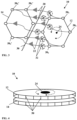
- the closed loop configuration of the first 12 and second 14 antenna arrays provides the transponder 10 of the present invention with an ability for omni-directional collection and transmission of electromagnetic signals, i.e. the transponder is capable of collecting electromagnetic signals (waveforms) arriving from substantially any direction and re-transmit corresponding signals with a desired angular shift relative to the collected signal.
- a planar closed-loop configuration of the array typically provides radiation collection from 360 degrees around the antenna array. This is while the exact configuration of the antenna elements (i.e. antenna elements type/polarization/orientation) may vary with the degree of radiation collection outside of a plane defined by the array. Specifically, the configuration/type of the antenna elements and the corresponding structure of their elemental beam actually define preferred directions for EM radiation collection transmission (e.g. shape, polarization and orientation of the reception/transmission beams).
- the transponder 10 includes two circular antenna arrays 12 and 14 (i.e. polygonal arrays) arranged one on top of the other and independently rotatable with respect to one other about a common axis 24.
- Each of the first and second antenna arrays includes a plurality of antenna elements 50.
- the antenna elements of the different arrays are paired between them to form a plurality of receiving-transmitting pairs.
- Other possible elements of the transponder such as wired connection lines, actuation module, control unit, signal amplifiers etc, may optionally be located near the rotation axis (e.g. within the circle created by the antenna arrays to reduce/prevent interference on the connection lines).
- antenna elements 50 are shown as having single orientation, it should be noted that the antenna elements of the transponder according to the present invention may be configured as electric monopole, electric dipole, magnetic dipole or any other type of antenna elements, and may be positioned with any orientation to collect or transmit EM radiation of any polarization.
- Antenna elements or each array may be arranged with the same or different orientation to interact with EM radiation of the same or different (e.g. orthogonal) polarization.
- antenna elements of each pair may be of a similar orientation/polarization or of different orientation/polarization. Such polarization variation may cause the transponder to repeat/transpond collected signals with the desired angular shift and with an altered polarization.
- a signal transmission network comprising one or more transponder systems as described above.
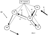
- the transponder systems 10a-10d are positioned successively along a predetermined signal path/propagation trajectory and each of them is configured to receive an EM signal/waveform and transmit a corresponding EM signal/waveform with a desired/predetermined angular shift with respect to the received signal/waveform.
- Transponder system 10e is positioned to enable an alternative signal trajectory, enabled by varying the angular shift provided by transponder system 10b.
- each of the transponder systems 10a-10e is configured to repeat collected EM signals/waveforms with a selected angular shift in accordance with a desired signal path/trajectory, e.g. in accordance with cornering angles associated with the desired trajectory segment where the transponder systems are located.
- transponder system 10a receives input signal/waveform W, and redirects a corresponding output signal W' along a segment S 1 of the trajectory towards a selected destination where system 10b is located; system 10b generates a corresponding output signal W" to propagate along a selected successive trajectory segment (e.g.
- Each of the transponder systems 10a-10e of the signal transmission network 100 receives and transmits signals from a certain selected preceding transponder system (located upstream thereof with respect to the desired signal path/trajectory) to a selected successive transponder system (located downstream thereof along the selected path).
- the signal transmission network 100 may include, or be associated with, one or more signal sources (transmission utilities) which are capable of feeding the network 100 with signals/waveforms to be wirelessly transmitted therethrough along a selected trajectory. Additionally, the signal transmission network 100 may also include, or be associated with, one or more signal receivers (receiving utilities) which are capable of collecting signals /waveforms which are wirelessly propagated/transmitted along a selected trajectory in the network 100.
- the signal transmission network 100 also includes a controller 200 connected to one or more of the transponder systems (by wired or wireless connection).
- the controller 200 may be configured to utilize data indicative of a desired trajectory(ies) for signal transmission through the signal transmission network 100 and is configured for generating operational data for operating the one or more transponder systems to adjust their angular shift for establishing the desired trajectory.
- the controller may communicate the operational data/instructions to the one or more transponder systems 10a-10e for rotating their rotatable antenna array(s) to vary the selected angular shift between collected and collectively transmitted EM signals/waveforms and thereby establish their trajectory.
- the controller 200 may be associated with a wired and/or wireless communication module (not specifically shown) capable of communicating operational instructions/data to the communication modules (i.e. 72 in Fig. 1 above) of the one or more transponder systems 10a-10e .
- the operational instructions may be communicated by utilizing the signal transmission network 100 itself.
- the operational data/instructions for each of the transponder systems 10a-10e along the route may be encoded to signal/waveform which is to be transmitted through the selected route while each of the communication modules (i.e. 72 ) may be adapted for identifying these encoded instructions in the waveform and operate their respective transponder systems accordingly (e.g. operate their respective actuation module).
- the signal trajectory/route provided by the transmission network 100 may be controllably adjusted by varying the angular shift provided by any one of the transponder systems 10a-10e .
- the rotatable antenna array of the transponder systems along the desired route may be rotated to provide suitable angular shifts of signal retransmission thereby to establish a transmission path along the desired route for directing signal transmission along the new route.
- each transponder system configured as described above provides a certain/selected angular shift between the collected and transmitted signals irrespective of the direction of the received signals.
- the direction of a signal transmitted by a certain transponder system relates to the direction from which the signal is received. Therefore, the angular shifts provided by any of the transponder systems 10a-10e of the signal transmission network 100 should be adjusted to comply with the selected trajectory (as may be operated by the controller 200 ).
- the respective locations of the transponder systems 10a-10e in the network 100 may be selected to provide more than one possible route.
- transponder system 10b may be operated to provide a certain angular shift, directing signals propagating along segment S 1 towards segment S 2 , or a certain different angular shift directing the signals arriving through segment S 1 to propagate along segment S 3 .
- locations of the transponder systems 10a-10e in the signal transmission network may be arranged to enable dynamic establishment of multiple concurrent signal transmission trajectories through the network (e.g. the different trajectories may be between pluralities of transmitters to a plurality of receivers).
- the transponder systems may be located in a lattice formation and/or the location of one or more of the transponder systems may be configured to enable concurrent signal repetition/replication between two pairs of signal sources and destinations (e.g. other transponders and/or receivers and transmitters).
- the present invention provides a simple configuration of a reliable and efficient transponder system enabling controllable adjustment of the angular shift between the received and repeated signals/waveforms and thus being capable of desirably varying its repeating pattern. Also, the invention provides a signal transmission network comprising a plurality of transponder systems and capable of exploiting the adjustability of the angular shift of the transponder systems to enable establishment of selected transmission paths.
Landscapes
- Variable-Direction Aerials And Aerial Arrays (AREA)
- Near-Field Transmission Systems (AREA)
Claims (15)
- Transpondersystem (10), umfassend:eine erste Antennengruppe (12) und eine zweite Antennengruppe (14), jeweils umfassend eine Vielzahl von Antennenelementen (50, 50'), die in einer vorbestimmten Geometrie angeordnet sind, wobei die Antennenelemente (50) der ersten Antennengruppe (12) jeweils durch jeweilige Verbindungsleitungen (20) mit entsprechenden Antennenelementen (50') der zweiten Antennengruppe (14) verbunden sind, um eine Vielzahl von Empfangs-/Sendepaaren von Antennenelementen zu bilden, wobei mindestens eine von der ersten und der zweiten Antennengruppe (12, 14) in Bezug auf die andere um mindestens eine vorbestimmte Drehachse (24) drehbar ist;ein Betätigungsmodul (75), das mit der mindestens einen drehbaren Antennengruppe (12, 14) verbunden und konfiguriert ist, um eine steuerbare Drehung der drehbaren Antennengruppe (12, 14) um die mindestens eine vorbestimmte Drehachse (24) zu ermöglichen;eine Steuereinheit (70), die mit dem Betätigungsmodul (75) verbunden und konfiguriert ist, um Daten zu empfangen, die indikativ für eine gewünschte Winkelverschiebung zwischen einer Ausbreitungsrichtung der Ausgangssignal-Wellenfront in Bezug auf die Ausbreitungsrichtung der gesammelten Signalwellenform sind, und um das Betätigungsmodul (75) zu betätigen, um einen relativen Winkel zwischen der ersten und der zweiten Antennengruppe (12, 14) zu variieren, um die Winkelverschiebung bereitzustellen,wobei die Empfangs-/Sendepaare konfiguriert sind, um ein elektromagnetisches Eingangssignal durch ein Antennenelement (50) zu empfangen, das Signal über seine entsprechende Verbindungsleitung (20) zu den entsprechenden Antennenelementen (50') des Empfangs-/Sendepaares zu leiten und ein entsprechendes Ausgangssignal durch sein entsprechendes Antennenelement zu senden, wodurch ein gemeinsames Sammeln einer Signalwellenform und ein Senden einer entsprechenden Ausgangssignal-Wellenform mit selektiver Variation der Ausbreitungsrichtung der Ausgangssignal-Wellenform in Bezug auf eine Ausbreitungsrichtung der gesammelten Signalwellenform ermöglicht wird.
- Transponder nach Anspruch 1, wobei jedes Antennenelement (50) der ersten Antennengruppe (12) in Übereinstimmung mit einer sequentiellen Anordnung der Antennenelemente innerhalb der Gruppen mit einem entsprechenden Antennenelement (50') der zweiten Gruppe (14) verbunden ist, um die Empfangs-/Sendepaare zu bilden.
- Transponder nach Anspruch 1 oder 2, wobei die Verbindungsleitungen (20) von im Wesentlichen ähnlicher Länge und ähnlichen elektrischen Eigenschaften sind.
- Transponder nach einem der vorherigen Ansprüche, wobei die erste und die zweite Antennengruppe (12, 14) mit im Wesentlichen ähnlichen Geometrien konfiguriert sind.
- Transponder nach einem der vorherigen Ansprüche, wobei die erste und die zweite Antennengruppe (12, 14) mindestens eine der folgenden Konfigurationen aufweisen: die erste und die zweite Antennengruppe weisen eine lineare Geometrie auf; die erste und die zweite Antennengruppe weisen zweidimensionale Geometrien auf; die erste und die zweite Antennengruppe weisen einen im Wesentlichen ähnlichen Abstand zwischen ihren Antennenelementen auf; die erste und die zweite Antennengruppe befinden sich auf einer parallelen Ebene, die sich mit einer Drehachse der mindestens einen drehbaren Antennengruppe schneidet.
- Transponder nach einem der vorherigen Ansprüche, wobei die erste und die zweite Antennengruppe (12, 14) geschlossene Schleifen sind.
- Transponder nach Anspruch 6, wobei die erste und die zweite Antennengruppe (12, 14) mindestens eine der folgenden Konfigurationen aufweisen: die erste und die zweite Antennengruppe (12, 14) sind kreisförmige oder polygonale Gruppen; die erste und die zweite Antennengruppe (12, 14) sind konzentrisch in Bezug aufeinander, die mindestens eine Drehachse (24) umfasst eine Achse, die eine Ebene schneidet, die durch mindestens eine der Antennengruppen (12, 14) in einer Mitte der geschlossenen Schleife definiert ist; die erste und die zweite Antennengruppe (12, 14) sind in parallelen Ebenen angeordnet.
- Transponder nach Anspruch 1, wobei die Steuereinheit (70) ein drahtloses Kommunikationsmodul (72) umfasst, das konfiguriert ist, um geeignete Steuersignale zu empfangen, die indikativ für die Winkelverschiebung sind, wobei die Steuereinheit (70) auf die geeigneten Steuersignale anspricht, um das Betätigungsmodul (75) entsprechend zu betreiben, um dadurch eine ferngesteuerte Variation des relativen Winkels zwischen der ersten und der zweiten Antennengruppe (12, 14) zu ermöglichen.
- Transponder nach einem der vorherigen Ansprüche, umfassend eine Vielzahl von Signalverstärkern (22), die jeweils mit den Verbindungsleitungen (20) assoziiert und konfiguriert sind, um Signale verstärken, die zwischen den assoziierten Antennenelementen (50, 50') des entsprechenden Empfangs-/Sendepaars verlaufen, wobei die Vielzahl von Signalverstärkern (22) konfiguriert ist, um eine im Wesentlichen ähnliche Signalverstärkung bereitzustellen.
- Transponder nach einem der vorherigen Ansprüche, wobei die Vielzahl von Antennenelementen (50, 50') Antennenelemente umfassen, die konfiguriert sind, um elektromagnetische Strahlung mit zwei oder mehreren unterschiedlichen Polarisationsausrichtungen zu empfangen und zu senden.
- Transponder nach einem der vorherigen Ansprüche, umfassend ein Isolationssystem (30), das konfiguriert ist, um ein Übersprechen zwischen Antennenelementen (50, 50') der ersten und der zweiten Antennengruppe (12, 14) zu reduzieren.
- Transponder nach Anspruch 11, umfassend eine Vielzahl von Signalverstärkern (22), die jeweils mit den Verbindungsleitungen (20) assoziiert sind, und wobei das Isolationssystem konfiguriert ist, um das Übersprechen um einen Faktor zu unterdrücken, der größer ist als die Signalverstärkung, die von den Signalverstärkern (22) bereitgestellt wird.
- Transponder nach Anspruch 11 oder 12, wobei das Isolationssystem (30) mindestens eines von Folgenden umfasst: (a) eine oder mehrere parasitäre Antennen; (b) eine elektromagnetische Isolationsschicht; (c) einen oder mehrere Frequenzteiler/-vervielfacher, die konfiguriert sind, um die Frequenz der gesendeten Signale in Bezug auf die Frequenz der empfangenen Signale entsprechend den Abständen der Antennenelemente der ersten und der zweiten Antennengruppe (12, 14) zu ändern; und (d) ein oder mehrere Filter, die konfiguriert sind, um Frequenzkomponenten herauszufiltern, die mit den empfangenen Signalen assoziiert sind, während Übertragungsfrequenzkomponenten gemäß Abständen von Antennenelementen mit der ersten und der zweiten Antennengruppe (12, 14) assoziiert sind.
- Signalübertragungsnetz (100), umfassend zwei oder mehrere Transpondersysteme (10a, 10b, 10c, 10d, 10e), wobei mindestens ein Transpondersystem (10a, 10b, 10c, 10d, 10e) gemäß einem der vorherigen Ansprüche konfiguriert ist; wobei die zwei oder mehreren Transponder (10a, 10b, 10c, 10d, 10e) an gewissen Orten angeordnet sind, um eine Herstellung einer Signalausbreitungstrajektorie entlang des Signalübertragungsnetzwerks (100) zu ermöglichen, wobei ein solches Segment (S1, S2, S3) der Signalausbreitungstrajektorie zwischen zwei benachbarten Transpondersystemen (10a, 10b, 10c, 10d, 10e) definiert ist; wobei eine Kontrolle über die Winkelverschiebung, die von dem mindestens einen Transpondersystem (10a, 10b, 10c, 10d, 10e) bereitgestellt wird, eine Herstellung einer gewünschten Signalausbreitungstrajektorie entlang des Netzwerks (100) ermöglicht.
- Signalübertragungsnetzwerk nach Anspruch 14, umfassend eine Steuerung (200), die mit dem mindestens einen Transpondersystem (10a, 10b, 10c, 10d, 10e) verbunden werden kann und konfiguriert ist und betrieben werden kann, um Daten zu verwenden, die indikativ für eine gewünschte Trajektorie zur Signalübertragung entlang des Signalübertragungsnetzwerks (100) sind, mindestens eine entsprechende Winkelverschiebung für das mindestens eine Transpondersystem (10a, 10b, 10c, 10d, 10e) zu bestimmen und Betriebsanweisungen, die indikativ für die mindestens eine entsprechende Winkelverschiebung sind, an das mindestens eine Transpondersystem (10a, 10b, 10c, 10d, 10e) zu übermitteln, um dadurch die gewünschte Trajektorie durch das Signalübertragungsnetzwerk (100) herzustellen.
Applications Claiming Priority (2)
| Application Number | Priority Date | Filing Date | Title |
|---|---|---|---|
| IL223415A IL223415A (en) | 2012-12-04 | 2012-12-04 | A rotating transducer system |
| PCT/IL2013/050985 WO2014087398A1 (en) | 2012-12-04 | 2013-12-01 | Rotatable transponder system |
Publications (2)
| Publication Number | Publication Date |
|---|---|
| EP2929591A1 EP2929591A1 (de) | 2015-10-14 |
| EP2929591B1 true EP2929591B1 (de) | 2023-06-07 |
Family
ID=49887022
Family Applications (1)
| Application Number | Title | Priority Date | Filing Date |
|---|---|---|---|
| EP13815166.7A Active EP2929591B1 (de) | 2012-12-04 | 2013-12-01 | Drehbares transpondersystem |
Country Status (6)
| Country | Link |
|---|---|
| US (1) | US10998644B2 (de) |
| EP (1) | EP2929591B1 (de) |
| AU (1) | AU2013353641B2 (de) |
| IL (1) | IL223415A (de) |
| SG (2) | SG11201503819TA (de) |
| WO (1) | WO2014087398A1 (de) |
Families Citing this family (12)
| Publication number | Priority date | Publication date | Assignee | Title |
|---|---|---|---|---|
| FR3028075B1 (fr) * | 2014-11-04 | 2017-05-05 | Ask Sa | Support mince de dipositif radiofrequence a l'epreuve des perforations |
| JP6129427B1 (ja) * | 2016-03-25 | 2017-05-17 | 三菱電機株式会社 | 分散アンテナシステム |
| DE102016220866A1 (de) * | 2016-10-24 | 2018-04-26 | Robert Bosch Gmbh | Kommunikationsanordnung zur drahtlosen Kommunikation und Verfahren zum Steuern einer solchen Kommunikationsanordnung |
| US10051497B1 (en) * | 2017-07-19 | 2018-08-14 | Sprint Communications Company L.P. | Optimizing a relay antenna in a communications network |
| JP2020197433A (ja) * | 2019-05-31 | 2020-12-10 | キヤノン株式会社 | 情報処理装置および位置検出システム |
| MX2022005127A (es) * | 2019-10-29 | 2022-08-04 | Tmrw Life Sciences Inc | Aparato para facilitar la transferencia de especimenes biologicos almacenados en condiciones criogenicas. |
| KR102644271B1 (ko) * | 2020-03-02 | 2024-03-06 | 삼성전자주식회사 | 무선 통신을 위한 안테나 배치 시스템 및 방법 |
| US11817187B2 (en) | 2020-05-18 | 2023-11-14 | TMRW Life Sciences, Inc. | Handling and tracking of biological specimens for cryogenic storage |
| JP7610303B2 (ja) | 2020-09-24 | 2025-01-08 | ティーエムアールダブリュ ライフサイエンシーズ,インコーポレイテツド | 極低温条件で保管された生物学的試料の移送を容易にするためのワークステーション及び装置 |
| EP4252009B1 (de) | 2021-01-13 | 2025-03-05 | TMRW Life Sciences, Inc. | System zur entnahme und/oder platzierung von probenbehältern |
| US12527318B2 (en) | 2021-10-08 | 2026-01-20 | TMRW Life Sciences, Inc. | Systems, apparatus and methods to pick and/or place specimen containers |
| CN114188726B (zh) * | 2021-10-29 | 2024-04-26 | 电子科技大学长三角研究院(湖州) | 一种有源智能反射表面 |
Family Cites Families (23)
| Publication number | Priority date | Publication date | Assignee | Title |
|---|---|---|---|---|
| US2908002A (en) | 1955-06-08 | 1959-10-06 | Hughes Aircraft Co | Electromagnetic reflector |
| US3518672A (en) * | 1969-02-28 | 1970-06-30 | Raytheon Co | Radar transponder |
| US3680137A (en) * | 1970-12-03 | 1972-07-25 | Us Navy | Circular symmetric bootlace lens system |
| US3715749A (en) * | 1971-05-11 | 1973-02-06 | Raytheon Co | Multi-beam radio frequency system |
| US3731313A (en) * | 1971-09-09 | 1973-05-01 | Tokyo Shibaura Electric Co | Van-atta array antenna device |
| US3736592A (en) | 1972-05-25 | 1973-05-29 | Us Navy | Multiple beam retrodirective array with circular symmetry |
| US4001691A (en) * | 1975-01-30 | 1977-01-04 | Gruenberg Elliot | Communications relay system |
| US4042926A (en) * | 1975-03-27 | 1977-08-16 | The United States Of America As Represented By The Administrator Of The National Aeronautics And Space Administration | Automatic transponder |
| US4121221A (en) * | 1977-03-14 | 1978-10-17 | Raytheon Company | Radio frequency array antenna system |
| US4806938A (en) * | 1984-11-20 | 1989-02-21 | Raytheon Company | Integrated self-adaptive array repeater and electronically steered directional transponder |
| US5179386A (en) * | 1986-08-21 | 1993-01-12 | Rudish Ronald M | Cylindrical phased array antenna system to produce wide open coverage of a wide angular sector with high directive gain and strong capability to resolve multiple signals |
| US5543807A (en) * | 1992-11-25 | 1996-08-06 | Loral Corporation | Electronic commutation switch for cylindrical array antennas |
| US5686928A (en) * | 1995-10-13 | 1997-11-11 | Lockheed Martin Corporation | Phased array antenna for radio frequency identification |
| US5945938A (en) * | 1996-11-14 | 1999-08-31 | National University Of Singapore | RF identification transponder |
| EP1269643A1 (de) * | 2000-03-01 | 2003-01-02 | Geir Monsen Vavik | Transponder und transpondersystem |
| WO2002027863A1 (en) * | 2000-09-29 | 2002-04-04 | British Telecommunications Public Limited Company | Antenna assembly |
| US6480167B2 (en) * | 2001-03-08 | 2002-11-12 | Gabriel Electronics Incorporated | Flat panel array antenna |
| US7944396B2 (en) * | 2007-04-09 | 2011-05-17 | Physical Domains, LLC | Retrodirective transmit and receive radio frequency system based on pseudorandom modulated waveforms |
| US8446253B2 (en) * | 2009-03-11 | 2013-05-21 | Checkpoint Systems, Inc. | Localization using virtual antenna arrays in modulated backscatter RFID systems |
| US8633856B2 (en) * | 2009-07-02 | 2014-01-21 | Blackberry Limited | Compact single feed dual-polarized dual-frequency band microstrip antenna array |
| US9232558B1 (en) * | 2010-06-28 | 2016-01-05 | Google Inc. | Multi sector antenna and mesh network system |
| US20120086602A1 (en) * | 2010-10-08 | 2012-04-12 | Electronics And Telecommunications Research Institute | Hybrid beam forming apparatus in wideband wireless communication system |
| US8674870B2 (en) * | 2011-01-19 | 2014-03-18 | Photonic Systems, Inc. | Methods and apparatus for active reflection |
-
2012
- 2012-12-04 IL IL223415A patent/IL223415A/en active IP Right Grant
-
2013
- 2013-12-01 AU AU2013353641A patent/AU2013353641B2/en not_active Ceased
- 2013-12-01 SG SG11201503819TA patent/SG11201503819TA/en unknown
- 2013-12-01 EP EP13815166.7A patent/EP2929591B1/de active Active
- 2013-12-01 WO PCT/IL2013/050985 patent/WO2014087398A1/en not_active Ceased
- 2013-12-01 SG SG10201704408PA patent/SG10201704408PA/en unknown
- 2013-12-01 US US14/441,787 patent/US10998644B2/en active Active
Also Published As
| Publication number | Publication date |
|---|---|
| SG10201704408PA (en) | 2017-06-29 |
| IL223415A (en) | 2017-06-29 |
| WO2014087398A1 (en) | 2014-06-12 |
| AU2013353641B2 (en) | 2017-09-07 |
| US20150295328A1 (en) | 2015-10-15 |
| US10998644B2 (en) | 2021-05-04 |
| SG11201503819TA (en) | 2015-06-29 |
| AU2013353641A1 (en) | 2015-05-21 |
| EP2929591A1 (de) | 2015-10-14 |
Similar Documents
| Publication | Publication Date | Title |
|---|---|---|
| EP2929591B1 (de) | Drehbares transpondersystem | |
| CN107403991B (zh) | 超超宽带aesa的系统和方法 | |
| US20140152523A1 (en) | Device for decoupling antennas in compact antenna array and antenna array with the device | |
| CN104823323B (zh) | 具有4tx/4rx三频带天线布置的无线通信节点 | |
| CN104660311A (zh) | 一种波束赋形方法、确定初始波束索引集合的方法及装置 | |
| US3396398A (en) | Small unidirectional antenna array employing spaced electrically isolated antenna elements | |
| CN105051971A (zh) | 移相器、天线以及无线装置 | |
| CN104685708A (zh) | 具有用于双频带接收和传送的天线布置的无线通信节点 | |
| Holzman | On the use of dummy elements to match edge elements in transmit arrays | |
| JP2012124901A (ja) | マルチビームアンテナのシステム | |
| EP2880462B1 (de) | Transpondervorrichtung | |
| CN109786978B (zh) | 一种实现卫星与地面通信的地面站 | |
| CN105762534B (zh) | 宽角度高增益北斗导航系统星载低剖面天线阵列 | |
| CN105186137A (zh) | 一种基于多谐振结构的单馈电抗多径自适应天线 | |
| CN218824699U (zh) | 一种全空域接收转发的多模转发式导航欺骗干扰系统 | |
| US11902005B2 (en) | Relay apparatus and relay method | |
| CN110521130B (zh) | 利用干涉图案的mimo系统和方法 | |
| CN103367875A (zh) | 半波阵子阵元及其组成的微带阵列天线 | |
| KR101421141B1 (ko) | 대수주기 다이폴 배열(lpda) 안테나를 위한 인쇄 회로 기판 및 통합 시스템 | |
| Siddiqui et al. | Concept of beam steerable transponder based on load modulation | |
| Lee et al. | An Efficient RF Power Transfer Scheme using Location-based Phase-controlled Array Antenna | |
| US2133806A (en) | Radio communication system | |
| US20120268346A1 (en) | Biologically inspired beam forming small antenna arrays | |
| WO2003067710A1 (en) | System for three-dimensional evaluation | |
| CN113517537A (zh) | 立体式新型射频前端装置 |
Legal Events
| Date | Code | Title | Description |
|---|---|---|---|
| PUAI | Public reference made under article 153(3) epc to a published international application that has entered the european phase |
Free format text: ORIGINAL CODE: 0009012 |
|
| 17P | Request for examination filed |
Effective date: 20150629 |
|
| AK | Designated contracting states |
Kind code of ref document: A1 Designated state(s): AL AT BE BG CH CY CZ DE DK EE ES FI FR GB GR HR HU IE IS IT LI LT LU LV MC MK MT NL NO PL PT RO RS SE SI SK SM TR |
|
| AX | Request for extension of the european patent |
Extension state: BA ME |
|
| DAX | Request for extension of the european patent (deleted) | ||
| STAA | Information on the status of an ep patent application or granted ep patent |
Free format text: STATUS: EXAMINATION IS IN PROGRESS |
|
| 17Q | First examination report despatched |
Effective date: 20200512 |
|
| GRAP | Despatch of communication of intention to grant a patent |
Free format text: ORIGINAL CODE: EPIDOSNIGR1 |
|
| STAA | Information on the status of an ep patent application or granted ep patent |
Free format text: STATUS: GRANT OF PATENT IS INTENDED |
|
| INTG | Intention to grant announced |
Effective date: 20230102 |
|
| GRAS | Grant fee paid |
Free format text: ORIGINAL CODE: EPIDOSNIGR3 |
|
| GRAA | (expected) grant |
Free format text: ORIGINAL CODE: 0009210 |
|
| STAA | Information on the status of an ep patent application or granted ep patent |
Free format text: STATUS: THE PATENT HAS BEEN GRANTED |
|
| AK | Designated contracting states |
Kind code of ref document: B1 Designated state(s): AL AT BE BG CH CY CZ DE DK EE ES FI FR GB GR HR HU IE IS IT LI LT LU LV MC MK MT NL NO PL PT RO RS SE SI SK SM TR |
|
| REG | Reference to a national code |
Ref country code: GB Ref legal event code: FG4D |
|
| REG | Reference to a national code |
Ref country code: CH Ref legal event code: EP Ref country code: AT Ref legal event code: REF Ref document number: 1577703 Country of ref document: AT Kind code of ref document: T Effective date: 20230615 Ref country code: DE Ref legal event code: R096 Ref document number: 602013083966 Country of ref document: DE |
|
| REG | Reference to a national code |
Ref country code: LT Ref legal event code: MG9D |
|
| REG | Reference to a national code |
Ref country code: NL Ref legal event code: MP Effective date: 20230607 |
|
| PG25 | Lapsed in a contracting state [announced via postgrant information from national office to epo] |
Ref country code: SE Free format text: LAPSE BECAUSE OF FAILURE TO SUBMIT A TRANSLATION OF THE DESCRIPTION OR TO PAY THE FEE WITHIN THE PRESCRIBED TIME-LIMIT Effective date: 20230607 Ref country code: NO Free format text: LAPSE BECAUSE OF FAILURE TO SUBMIT A TRANSLATION OF THE DESCRIPTION OR TO PAY THE FEE WITHIN THE PRESCRIBED TIME-LIMIT Effective date: 20230907 Ref country code: ES Free format text: LAPSE BECAUSE OF FAILURE TO SUBMIT A TRANSLATION OF THE DESCRIPTION OR TO PAY THE FEE WITHIN THE PRESCRIBED TIME-LIMIT Effective date: 20230607 |
|
| REG | Reference to a national code |
Ref country code: AT Ref legal event code: MK05 Ref document number: 1577703 Country of ref document: AT Kind code of ref document: T Effective date: 20230607 |
|
| PG25 | Lapsed in a contracting state [announced via postgrant information from national office to epo] |
Ref country code: RS Free format text: LAPSE BECAUSE OF FAILURE TO SUBMIT A TRANSLATION OF THE DESCRIPTION OR TO PAY THE FEE WITHIN THE PRESCRIBED TIME-LIMIT Effective date: 20230607 Ref country code: NL Free format text: LAPSE BECAUSE OF FAILURE TO SUBMIT A TRANSLATION OF THE DESCRIPTION OR TO PAY THE FEE WITHIN THE PRESCRIBED TIME-LIMIT Effective date: 20230607 Ref country code: LV Free format text: LAPSE BECAUSE OF FAILURE TO SUBMIT A TRANSLATION OF THE DESCRIPTION OR TO PAY THE FEE WITHIN THE PRESCRIBED TIME-LIMIT Effective date: 20230607 Ref country code: LT Free format text: LAPSE BECAUSE OF FAILURE TO SUBMIT A TRANSLATION OF THE DESCRIPTION OR TO PAY THE FEE WITHIN THE PRESCRIBED TIME-LIMIT Effective date: 20230607 Ref country code: HR Free format text: LAPSE BECAUSE OF FAILURE TO SUBMIT A TRANSLATION OF THE DESCRIPTION OR TO PAY THE FEE WITHIN THE PRESCRIBED TIME-LIMIT Effective date: 20230607 Ref country code: GR Free format text: LAPSE BECAUSE OF FAILURE TO SUBMIT A TRANSLATION OF THE DESCRIPTION OR TO PAY THE FEE WITHIN THE PRESCRIBED TIME-LIMIT Effective date: 20230908 |
|
| PGFP | Annual fee paid to national office [announced via postgrant information from national office to epo] |
Ref country code: FR Payment date: 20230929 Year of fee payment: 11 |
|
| PG25 | Lapsed in a contracting state [announced via postgrant information from national office to epo] |
Ref country code: FI Free format text: LAPSE BECAUSE OF FAILURE TO SUBMIT A TRANSLATION OF THE DESCRIPTION OR TO PAY THE FEE WITHIN THE PRESCRIBED TIME-LIMIT Effective date: 20230607 |
|
| PG25 | Lapsed in a contracting state [announced via postgrant information from national office to epo] |
Ref country code: SK Free format text: LAPSE BECAUSE OF FAILURE TO SUBMIT A TRANSLATION OF THE DESCRIPTION OR TO PAY THE FEE WITHIN THE PRESCRIBED TIME-LIMIT Effective date: 20230607 |
|
| PGFP | Annual fee paid to national office [announced via postgrant information from national office to epo] |
Ref country code: GB Payment date: 20231012 Year of fee payment: 11 |
|
| PG25 | Lapsed in a contracting state [announced via postgrant information from national office to epo] |
Ref country code: IS Free format text: LAPSE BECAUSE OF FAILURE TO SUBMIT A TRANSLATION OF THE DESCRIPTION OR TO PAY THE FEE WITHIN THE PRESCRIBED TIME-LIMIT Effective date: 20231007 |
|
| PG25 | Lapsed in a contracting state [announced via postgrant information from national office to epo] |
Ref country code: SM Free format text: LAPSE BECAUSE OF FAILURE TO SUBMIT A TRANSLATION OF THE DESCRIPTION OR TO PAY THE FEE WITHIN THE PRESCRIBED TIME-LIMIT Effective date: 20230607 Ref country code: SK Free format text: LAPSE BECAUSE OF FAILURE TO SUBMIT A TRANSLATION OF THE DESCRIPTION OR TO PAY THE FEE WITHIN THE PRESCRIBED TIME-LIMIT Effective date: 20230607 Ref country code: RO Free format text: LAPSE BECAUSE OF FAILURE TO SUBMIT A TRANSLATION OF THE DESCRIPTION OR TO PAY THE FEE WITHIN THE PRESCRIBED TIME-LIMIT Effective date: 20230607 Ref country code: PT Free format text: LAPSE BECAUSE OF FAILURE TO SUBMIT A TRANSLATION OF THE DESCRIPTION OR TO PAY THE FEE WITHIN THE PRESCRIBED TIME-LIMIT Effective date: 20231009 Ref country code: IS Free format text: LAPSE BECAUSE OF FAILURE TO SUBMIT A TRANSLATION OF THE DESCRIPTION OR TO PAY THE FEE WITHIN THE PRESCRIBED TIME-LIMIT Effective date: 20231007 Ref country code: EE Free format text: LAPSE BECAUSE OF FAILURE TO SUBMIT A TRANSLATION OF THE DESCRIPTION OR TO PAY THE FEE WITHIN THE PRESCRIBED TIME-LIMIT Effective date: 20230607 Ref country code: CZ Free format text: LAPSE BECAUSE OF FAILURE TO SUBMIT A TRANSLATION OF THE DESCRIPTION OR TO PAY THE FEE WITHIN THE PRESCRIBED TIME-LIMIT Effective date: 20230607 Ref country code: AT Free format text: LAPSE BECAUSE OF FAILURE TO SUBMIT A TRANSLATION OF THE DESCRIPTION OR TO PAY THE FEE WITHIN THE PRESCRIBED TIME-LIMIT Effective date: 20230607 |
|
| PGFP | Annual fee paid to national office [announced via postgrant information from national office to epo] |
Ref country code: IT Payment date: 20231110 Year of fee payment: 11 |
|
| PG25 | Lapsed in a contracting state [announced via postgrant information from national office to epo] |
Ref country code: PL Free format text: LAPSE BECAUSE OF FAILURE TO SUBMIT A TRANSLATION OF THE DESCRIPTION OR TO PAY THE FEE WITHIN THE PRESCRIBED TIME-LIMIT Effective date: 20230607 |
|
| REG | Reference to a national code |
Ref country code: DE Ref legal event code: R097 Ref document number: 602013083966 Country of ref document: DE |
|
| PLBE | No opposition filed within time limit |
Free format text: ORIGINAL CODE: 0009261 |
|
| STAA | Information on the status of an ep patent application or granted ep patent |
Free format text: STATUS: NO OPPOSITION FILED WITHIN TIME LIMIT |
|
| PG25 | Lapsed in a contracting state [announced via postgrant information from national office to epo] |
Ref country code: DK Free format text: LAPSE BECAUSE OF FAILURE TO SUBMIT A TRANSLATION OF THE DESCRIPTION OR TO PAY THE FEE WITHIN THE PRESCRIBED TIME-LIMIT Effective date: 20230607 |
|
| PG25 | Lapsed in a contracting state [announced via postgrant information from national office to epo] |
Ref country code: SI Free format text: LAPSE BECAUSE OF FAILURE TO SUBMIT A TRANSLATION OF THE DESCRIPTION OR TO PAY THE FEE WITHIN THE PRESCRIBED TIME-LIMIT Effective date: 20230607 |
|
| 26N | No opposition filed |
Effective date: 20240308 |
|
| PG25 | Lapsed in a contracting state [announced via postgrant information from national office to epo] |
Ref country code: SI Free format text: LAPSE BECAUSE OF FAILURE TO SUBMIT A TRANSLATION OF THE DESCRIPTION OR TO PAY THE FEE WITHIN THE PRESCRIBED TIME-LIMIT Effective date: 20230607 |
|
| REG | Reference to a national code |
Ref country code: CH Ref legal event code: PL |
|
| PG25 | Lapsed in a contracting state [announced via postgrant information from national office to epo] |
Ref country code: LU Free format text: LAPSE BECAUSE OF NON-PAYMENT OF DUE FEES Effective date: 20231201 |
|
| PG25 | Lapsed in a contracting state [announced via postgrant information from national office to epo] |
Ref country code: MC Free format text: LAPSE BECAUSE OF FAILURE TO SUBMIT A TRANSLATION OF THE DESCRIPTION OR TO PAY THE FEE WITHIN THE PRESCRIBED TIME-LIMIT Effective date: 20230607 |
|
| REG | Reference to a national code |
Ref country code: BE Ref legal event code: MM Effective date: 20231231 |
|
| PG25 | Lapsed in a contracting state [announced via postgrant information from national office to epo] |
Ref country code: MC Free format text: LAPSE BECAUSE OF FAILURE TO SUBMIT A TRANSLATION OF THE DESCRIPTION OR TO PAY THE FEE WITHIN THE PRESCRIBED TIME-LIMIT Effective date: 20230607 Ref country code: LU Free format text: LAPSE BECAUSE OF NON-PAYMENT OF DUE FEES Effective date: 20231201 |
|
| REG | Reference to a national code |
Ref country code: IE Ref legal event code: MM4A |
|
| PG25 | Lapsed in a contracting state [announced via postgrant information from national office to epo] |
Ref country code: IE Free format text: LAPSE BECAUSE OF NON-PAYMENT OF DUE FEES Effective date: 20231201 |
|
| PG25 | Lapsed in a contracting state [announced via postgrant information from national office to epo] |
Ref country code: BE Free format text: LAPSE BECAUSE OF NON-PAYMENT OF DUE FEES Effective date: 20231231 |
|
| PG25 | Lapsed in a contracting state [announced via postgrant information from national office to epo] |
Ref country code: CH Free format text: LAPSE BECAUSE OF NON-PAYMENT OF DUE FEES Effective date: 20231231 |
|
| PG25 | Lapsed in a contracting state [announced via postgrant information from national office to epo] |
Ref country code: IE Free format text: LAPSE BECAUSE OF NON-PAYMENT OF DUE FEES Effective date: 20231201 Ref country code: CH Free format text: LAPSE BECAUSE OF NON-PAYMENT OF DUE FEES Effective date: 20231231 Ref country code: BE Free format text: LAPSE BECAUSE OF NON-PAYMENT OF DUE FEES Effective date: 20231231 |
|
| PG25 | Lapsed in a contracting state [announced via postgrant information from national office to epo] |
Ref country code: BG Free format text: LAPSE BECAUSE OF FAILURE TO SUBMIT A TRANSLATION OF THE DESCRIPTION OR TO PAY THE FEE WITHIN THE PRESCRIBED TIME-LIMIT Effective date: 20230607 |
|
| PG25 | Lapsed in a contracting state [announced via postgrant information from national office to epo] |
Ref country code: BG Free format text: LAPSE BECAUSE OF FAILURE TO SUBMIT A TRANSLATION OF THE DESCRIPTION OR TO PAY THE FEE WITHIN THE PRESCRIBED TIME-LIMIT Effective date: 20230607 |
|
| PGFP | Annual fee paid to national office [announced via postgrant information from national office to epo] |
Ref country code: DE Payment date: 20241120 Year of fee payment: 12 |
|
| PG25 | Lapsed in a contracting state [announced via postgrant information from national office to epo] |
Ref country code: CY Free format text: LAPSE BECAUSE OF FAILURE TO SUBMIT A TRANSLATION OF THE DESCRIPTION OR TO PAY THE FEE WITHIN THE PRESCRIBED TIME-LIMIT; INVALID AB INITIO Effective date: 20131201 |
|
| PG25 | Lapsed in a contracting state [announced via postgrant information from national office to epo] |
Ref country code: HU Free format text: LAPSE BECAUSE OF FAILURE TO SUBMIT A TRANSLATION OF THE DESCRIPTION OR TO PAY THE FEE WITHIN THE PRESCRIBED TIME-LIMIT; INVALID AB INITIO Effective date: 20131201 |
|
| GBPC | Gb: european patent ceased through non-payment of renewal fee |
Effective date: 20241201 |
|
| PG25 | Lapsed in a contracting state [announced via postgrant information from national office to epo] |
Ref country code: IT Free format text: LAPSE BECAUSE OF NON-PAYMENT OF DUE FEES Effective date: 20241201 |
|
| PG25 | Lapsed in a contracting state [announced via postgrant information from national office to epo] |
Ref country code: GB Free format text: LAPSE BECAUSE OF NON-PAYMENT OF DUE FEES Effective date: 20241201 |
|
| PG25 | Lapsed in a contracting state [announced via postgrant information from national office to epo] |
Ref country code: FR Free format text: LAPSE BECAUSE OF NON-PAYMENT OF DUE FEES Effective date: 20241231 |
|
| PG25 | Lapsed in a contracting state [announced via postgrant information from national office to epo] |
Ref country code: TR Free format text: LAPSE BECAUSE OF FAILURE TO SUBMIT A TRANSLATION OF THE DESCRIPTION OR TO PAY THE FEE WITHIN THE PRESCRIBED TIME-LIMIT Effective date: 20230607 |