EP2928093A1 - Radio broadcast receiving apparatus and broadcast frequency detection method - Google Patents
Radio broadcast receiving apparatus and broadcast frequency detection method Download PDFInfo
- Publication number
- EP2928093A1 EP2928093A1 EP15156253.5A EP15156253A EP2928093A1 EP 2928093 A1 EP2928093 A1 EP 2928093A1 EP 15156253 A EP15156253 A EP 15156253A EP 2928093 A1 EP2928093 A1 EP 2928093A1
- Authority
- EP
- European Patent Office
- Prior art keywords
- frequency
- broadcast
- broadcastable
- reception
- frequencies
- Prior art date
- Legal status (The legal status is an assumption and is not a legal conclusion. Google has not performed a legal analysis and makes no representation as to the accuracy of the status listed.)
- Granted
Links
Images



Classifications
-
- H—ELECTRICITY
- H04—ELECTRIC COMMUNICATION TECHNIQUE
- H04H—BROADCAST COMMUNICATION
- H04H40/00—Arrangements specially adapted for receiving broadcast information
- H04H40/18—Arrangements characterised by circuits or components specially adapted for receiving
- H04H40/27—Arrangements characterised by circuits or components specially adapted for receiving specially adapted for broadcast systems covered by groups H04H20/53 - H04H20/95
-
- H—ELECTRICITY
- H04—ELECTRIC COMMUNICATION TECHNIQUE
- H04B—TRANSMISSION
- H04B1/00—Details of transmission systems, not covered by a single one of groups H04B3/00 - H04B13/00; Details of transmission systems not characterised by the medium used for transmission
- H04B1/06—Receivers
- H04B1/16—Circuits
-
- H—ELECTRICITY
- H04—ELECTRIC COMMUNICATION TECHNIQUE
- H04B—TRANSMISSION
- H04B17/00—Monitoring; Testing
- H04B17/30—Monitoring; Testing of propagation channels
- H04B17/309—Measuring or estimating channel quality parameters
- H04B17/318—Received signal strength
-
- H—ELECTRICITY
- H04—ELECTRIC COMMUNICATION TECHNIQUE
- H04H—BROADCAST COMMUNICATION
- H04H20/00—Arrangements for broadcast or for distribution combined with broadcast
- H04H20/65—Arrangements characterised by transmission systems for broadcast
- H04H20/71—Wireless systems
-
- H—ELECTRICITY
- H04—ELECTRIC COMMUNICATION TECHNIQUE
- H04H—BROADCAST COMMUNICATION
- H04H60/00—Arrangements for broadcast applications with a direct linking to broadcast information or broadcast space-time; Broadcast-related systems
- H04H60/35—Arrangements for identifying or recognising characteristics with a direct linkage to broadcast information or to broadcast space-time, e.g. for identifying broadcast stations or for identifying users
- H04H60/38—Arrangements for identifying or recognising characteristics with a direct linkage to broadcast information or to broadcast space-time, e.g. for identifying broadcast stations or for identifying users for identifying broadcast time or space
- H04H60/41—Arrangements for identifying or recognising characteristics with a direct linkage to broadcast information or to broadcast space-time, e.g. for identifying broadcast stations or for identifying users for identifying broadcast time or space for identifying broadcast space, i.e. broadcast channels, broadcast stations or broadcast areas
- H04H60/43—Arrangements for identifying or recognising characteristics with a direct linkage to broadcast information or to broadcast space-time, e.g. for identifying broadcast stations or for identifying users for identifying broadcast time or space for identifying broadcast space, i.e. broadcast channels, broadcast stations or broadcast areas for identifying broadcast channels
Definitions
- the present invention relates to a technique for detecting a frequency at which a receivable broadcast is performed in a radio broadcast receiving apparatus.
- a technique for allowing a radio broadcast receiving apparatus for receiving a radio broadcast to detect a frequency at which a receivable broadcast is performed a technique is known for searching for a frequency at which the value of reception strength (S meter value) is greater than a predetermined threshold value and is greater than the value of reception strength at a frequency adjacent to the frequency by one step while changing a frequency in predetermined steps and determining the retrieved frequency as a frequency at which a receivable broadcast is performed (see, for example, JP 2006-340004 A ).
- a frequency at which a broadcast is not actually performed may be incorrectly retrieved as a frequency at which a broadcast is performed in a frequency band in which a noise level is higher than the threshold value.
- the accuracy of search is low.
- the invention relates to a radio broadcast receiving apparatus and a method according to the independent claims. Embodiments are disclosed in the dependent claims.
- a radio broadcast receiving apparatus for receiving a radio broadcast performed with one of broadcastable frequencies arranged at predetermined frequency intervals in a predetermined frequency range.
- the radio broadcast receiving apparatus includes a receiving section configured to detect a broadcast signal of one of the broadcastable frequencies set as a reception target frequency and output the broadcast signal as a received signal, a demodulation section configured to demodulate the received signal to an audio signal and output the audio signal, a reception strength detection section configured to detect a strength of the received signal as a reception strength value at the broadcastable frequency set as the reception target frequency in the receiving section, and a reception control section including a broadcast frequency detection unit configured to detect a frequency at which a receivable broadcast is performed as a broadcast frequency.
- the broadcast frequency detected by the broadcast frequency detection unit is one of the broadcastable frequencies at which the reception strength value is greater than a predetermined threshold value, is equal to or greater than a criterion value determined in accordance with the reception strength value at the broadcastable frequency, and is greater than both the reception strength values at two of the broadcastable frequencies which are adjacent to the broadcastable frequency in an increasing frequency direction and a decreasing frequency direction.
- the criterion value increases with an increase in the reception strength value.
- the reception control section may further include a search control unit configured to cause the broadcast frequency detection unit to detect the broadcast frequency while sequentially changing in the increasing frequency direction or the decreasing frequency direction the broadcastable frequencies one of which is set as the reception target frequency in the receiving section, stop sequentially changing the broadcastable frequencies when the broadcast frequency is detected, and perform control processing so that a next reception target frequency becomes the detected broadcast frequency in the receiving section.
- a search control unit configured to cause the broadcast frequency detection unit to detect the broadcast frequency while sequentially changing in the increasing frequency direction or the decreasing frequency direction the broadcastable frequencies one of which is set as the reception target frequency in the receiving section, stop sequentially changing the broadcastable frequencies when the broadcast frequency is detected, and perform control processing so that a next reception target frequency becomes the detected broadcast frequency in the receiving section.
- the reception control section may further include a scan control unit and a preset frequency reception control unit.
- the scan control unit may cause the broadcast frequency detection unit to detect the broadcast frequency while sequentially changing in the increasing frequency direction or the decreasing frequency direction in the predetermined frequency range the broadcastable frequencies one of which is set as the reception target frequency in the receiving section and store the broadcastable frequencies each of which has been detected as the broadcast frequency as preset frequencies.
- the preset frequency reception control unit may set one of the stored preset frequencies selected by a user as the reception target frequency in the receiving section.
- a criterion value which is used to determine whether a broadcastable frequency is the broadcast frequency and is a condition used for the difference between reception strengths at broadcastable frequencies adjacent to each other, is set so that it increases with the increase in the reception strength at the broadcast frequency.
- a radio broadcast receiving apparatus includes an antenna 1, a tuner 2, an audio processing section 3, a speaker 4, a control section 5, an operation section 6, and a display device 7.
- the tuner 2 includes an RF amplifier 201, a mixer 202, an IF filter 203, an IF amplifier 204, a demodulator 205, an amplifier 206, a local oscillator 207, a PLL 208, an IF counter detection unit 209, an S meter detection unit 210, a reception control unit 211, and a memory 212.
- the antenna 1 receives a broadcast signal.
- the RF amplifier 201 amplifies a signal output from the antenna 1 and the mixer 202 mixes a signal output from the RF amplifier 201 and a local oscillation signal generated by the oscillator 207, so that the signal output from the antenna 1 is converted into an IF signal.
- the IF filter 203 selectively passes a signal component of a predetermined frequency in the IF signal output from the mixer 202.
- the IF amplifier 204 amplifies the IF signal that has passed through the IF filter 203.
- the demodulator 205 performs AM detection upon the IF signal amplified by the IF amplifier 204, thereby demodulating the IF signal to an audio signal.
- the amplifier 206 amplifies the audio signal output from the demodulator 205 and outputs the amplified audio signal to the audio processing section 3.
- a reception frequency to be received by the tuner 2 is determined in accordance with the oscillation frequency of a local oscillation signal generated by the local oscillator 207.
- the reception control unit 211 controls the division ratio of the PLL 208 and sets the oscillation frequency of a local oscillation signal, thereby controlling the reception frequency of the tuner 2.
- the S meter detection unit 210 detects the strength of the IF signal amplified by the IF amplifier 204 and outputs a result of the detection to the reception control unit 211 as an S meter value.
- An S meter value detected by the S meter detection unit 210 indicates the reception strength of a broadcast signal of a current reception frequency.
- the IF counter detection unit 209 detects the frequency of the IF signal amplified by the IF amplifier 204 and outputs a result of the detection to the reception control unit 211.
- the audio processing section 3 performs pieces of audio processing such as amplification and the change of a frequency characteristic on the received audio signal and outputs the processed audio signal to the speaker 4.
- the control section 5 provides user interfaces corresponding to the operation section 6 and the display device 7 and controls the reception frequency of the tuner 2 and the audio processing operation of the audio processing section 3 in accordance with a user's operation performed via the user interfaces.
- the broadcast frequency search process is started by the control section 5 in response to a user's search operation performed via the operation section 6.
- the user's search operation includes an up-search operation and a down-search operation.
- an increasing frequency direction is set as a search direction.
- a decreasing frequency direction is set as the search direction.
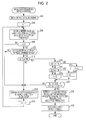
- Fig. 2 illustrates a broadcast frequency search process performed by the reception control unit 211 in the tuner 2.
- the reception control unit 211 controls the amplifier 206 so as to mute (stop) the output of an audio signal to the audio processing section 3 (step 202).
- An S meter value (reception strength value) detected by the S meter detection unit 210 at a current reception frequency is stored as S(i), and an IF counter value (frequency) detected by the IF counter detection unit 209 at the current reception frequency is stored as IFC(i) (step 206).
- i is equal to or greater than 3 (step 208).
- a reception frequency to be received by the tuner 2 is changed from the current reception frequency in the search direction by one step (step 214).
- the one step is a spacing between frequencies that can be used as broadcast frequencies, and is set to 9 kHz in AM broadcasting in Japan and is set to 9 or 10 kHz in AM broadcasting in foreign countries. In order to prevent a mutual interference, both of frequencies that are adjacent to each other by one step in the same area are not generally set as broadcast frequencies.
- the change of a reception frequency in the search direction by one step means that the reception frequency is increased by 9 kHz.
- the change of a reception frequency in the search direction by one step means that the reception frequency is decreased by 9 kHz.
- step 216 it is determined whether an IF counter value IFC(i - 1) stored for the last reception frequency (a reception frequency from which a current reception frequency has been changed in the search direction by one step) is in a predetermined frequency range (step 210).
- the IF counter value IFC(i - 1) is not in the predetermined frequency range, the reception frequency of the tuner 2 is changed from the current reception frequency in the search direction by one step (step 214) and i increments by one (step 216). The process returns to step 206.
- an S meter value S(i - 1) stored for the last reception frequency is equal to or greater than a predetermined threshold value Th0 (step 212).
- the reception frequency of the tuner 2 is changed from the current reception frequency in the search direction by one step (step 214) and i increments by one (step 216). The process returns to step 206.
- the value of X is set as follows under the assumption that ThL, ThM, L, M, and S are determined so that ThL > ThM and L > M > S are satisfied.
- X L is set (step 230).
- X M is set (step 232).
- the reception frequency of the tuner 2 is changed from the current reception frequency in the search direction by one step (step 214) and i increments by one (step 216). The process returns to step 206.
- the S meter value S(i - 1) at the last reception frequency is greater than the S meter value S(i - 2) at the second last reception frequency by X or more and is greater than the S meter value S(i) at the current reception frequency by X or more (step 224), the last reception frequency (a frequency at which the S meter value S(i - 1) has been detected) is detected as a broadcast frequency at which a receivable broadcast is performed and is set as the reception frequency of the tuner 2 (step 226).
- the reception control unit 211 controls the amplifier 206 so as to recover the output of an audio signal to the audio processing section 3 (step 228).
- the broadcast frequency search process ends. According to the above-described broadcast frequency search process performed by the reception control unit 211 in the tuner 2, a frequency fm at which the reception strength (the S meter value) is equal to or greater than the threshold value Th0 and is greater than both reception strengths at frequencies (fm - 1) and (fm + 1) adjacent to the frequency fm by one step by X or more is detected as a broadcast reception frequency that is a frequency at which a receivable broadcast is performed.
- the value of X increases with the increase in the reception strength (S meter value) at the frequency fm.
- S meter value the reception strength
- the threshold value Th0 34 dB ⁇ V
- ThL 55 dB ⁇ V
- M 10 dB ⁇ V
- Fig. 3A is a diagram illustrating an exemplary reception strength (S meter value) measured in a frequency range of 981 kHz to 1017 kHz.
- the horizontal axis represents a frequency and the vertical axis represents a reception strength (S meter value).
- a frequency at which a broadcast is actually performed is 999 kHz.
- 990 kHz and 1008 kHz are not detected as broadcast frequencies since the S meter value at 999 kHz that is adjacent to these frequencies by one step is greater than the S meter values at these frequencies.
- Fig. 3B illustrates an exemplary case in which a reception strength at a broadcast frequency is small, and, like Fig. 3A , illustrates reception strengths (S meter values) measured in the frequency range of 981 kHz to 1017 kHz. Referring to Fig. 3B , a frequency at which a broadcast is actually performed is also 999 kHz.
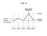
- Fig. 4 illustrates an exemplary case in which a noise level is high with some cause in a frequency range around a broadcast frequency, and illustrates reception strengths (S meter values) measured in the frequency range of 981 kHz to 1017 kHz.
- a frequency at which a broadcast is actually performed is 1008 kHz.
- 981 kHz, 999 kHz, and 1017 kHz are not detected as broadcast frequencies since S meter values at frequencies adjacent to these frequencies by one step are greater than S meter values at these frequencies.
- X 5 dB ⁇ V is used for 990 kHz.
- the difference X between reception strengths at frequencies adjacent to each other by one step which is a condition used to determine whether a frequency is the broadcast frequency, is set so that it increases with the increase in the reception strength at the broadcast frequency.
- both of frequencies adjacent to each other by one step in the same area are not generally set as broadcast frequencies.
- a frequency at which a receivable broadcast is performed can be accurately detected.
- a broadcast frequency scan process performed by the reception control unit 211 in the tuner 2 will be described.
- all of frequencies at which receivable broadcasts are performed are searched for, are associated with preset numbers as preset frequencies, and are stored in the memory 212.
- the control section 5 causes the reception control unit 211 to set a preset frequency associated with the selected preset number as the reception frequency of the tuner 2.
- Fig. 5 illustrates the broadcast frequency scan process performed by the reception control unit 211 in the tuner 2.
- the reception control unit 211 controls the amplifier 206 so as to mute (stop) the output of an audio signal to the audio processing section 3 (step 502).
- the reception frequency of the tuner 2 is set to a frequency that is lower than the lowest frequency in a scan frequency range (a frequency range between the highest frequency and the lowest frequency at which a receivable broadcast is probably performed: a frequency range of 531 kHz to 1602 kHz in the case of AM broadcasting in Japan) by one step (step 506).
- An S meter value (a reception strength value) detected by the S meter detection unit 210 at a current reception frequency is stored as S(i), and an IF counter value (frequency) detected by the IF counter detection unit 209 at the current reception frequency is stored as IFC(i) (step 508).
- step 510 it is determined whether i is equal to or greater than 3 (step 510). When i is not equal to or greater than 3, the process proceeds to step 516. On the other hand, when i is equal to or greater than 3 (step 510), it is determined whether an IF counter value IFC(i - 1) stored for the last reception frequency (a reception frequency from which a current reception frequency has been increased by one step) is in a predetermined frequency range (step 512). When the IF counter value IFC(i - 1) is not in the predetermined frequency range, the process proceeds to step 516.
- step 512 when the IF counter value IFC(i - 1) stored for the last reception frequency is in the predetermined frequency range (step 512), it is determined whether an S meter value S(i - 1) stored for the last reception frequency is equal to or greater than a predetermined threshold value Th0 (step 514). When the S meter value S(i - 1) is not equal to or greater than the predetermined threshold value Th0, the process proceeds to step 516.
- step 514 when the S meter value S(i - 1) stored for the last reception frequency is equal to or greater than the predetermined threshold value Th0 (step 514), the process proceeds to step 522.
- the S meter value S(i - 1) is equal to or greater than ThL (step 522)
- the S meter value S(i - 1) is less than ThL and is equal to or greater than ThM (steps 522 and 524)
- the S meter value S(i - 1) is less than ThM (step 524)
- step 528 When the S meter value S(i - 1) at the last reception frequency is not greater than the S meter value S(i - 2) at the second last reception frequency by X or more or is not greater than the S meter value S(i) at the current reception frequency by X or more (step 528), the process proceeds to step 516.
- the S meter value S(i - 1) at the last reception frequency is greater than the S meter value S(i - 2) at the second last reception frequency by X or more and is greater than the S meter value S(i) at the current reception frequency by X or more (step 528)
- the last reception frequency (a frequency at which the S meter value S(i - 1) has been detected) is detected as a preset frequency, is associated with a preset number j, and is stored in the memory 212 (step 530).
- j increments by one (step 532). The process proceeds to step 516.
- step 516 It is determined whether the current reception frequency is equal to a frequency to which the highest frequency in the scan frequency range has been increased by one step (step 516). When the current reception frequency is not equal to the frequency, the reception frequency of the tuner 2 is increased from the current reception frequency by one step (step 518) and i increments by one (step 520). The process returns to step 508.
- the reception control unit 211 controls the amplifier 206 so as to recover the output of an audio signal to the audio processing section 3 (step 532).
- the broadcast frequency scan process ends.
- the broadcast frequency scan process performed by the reception control unit 211 in the tuner 2 has been be described.
- This broadcast frequency scan process like in the case of the broadcast frequency search process, a frequency at which a receivable broadcast is performed can be accurately detected and be stored as a preset frequency.
Landscapes
- Engineering & Computer Science (AREA)
- Signal Processing (AREA)
- Computer Networks & Wireless Communication (AREA)
- Quality & Reliability (AREA)
- Physics & Mathematics (AREA)
- Electromagnetism (AREA)
- Circuits Of Receivers In General (AREA)
- Channel Selection Circuits, Automatic Tuning Circuits (AREA)
Abstract
Description
- The present invention relates to a technique for detecting a frequency at which a receivable broadcast is performed in a radio broadcast receiving apparatus.
- As a technique for allowing a radio broadcast receiving apparatus for receiving a radio broadcast to detect a frequency at which a receivable broadcast is performed, a technique is known for searching for a frequency at which the value of reception strength (S meter value) is greater than a predetermined threshold value and is greater than the value of reception strength at a frequency adjacent to the frequency by one step while changing a frequency in predetermined steps and determining the retrieved frequency as a frequency at which a receivable broadcast is performed (see, for example,
JP 2006-340004 A - When the above-described technique for searching for a frequency at which a broadcast is performed is used, a frequency at which a broadcast is not actually performed may be incorrectly retrieved as a frequency at which a broadcast is performed in a frequency band in which a noise level is higher than the threshold value. The accuracy of search is low.
- It is an object of the present invention to more accurately detect a frequency at which a broadcast is performed.
- The invention relates to a radio broadcast receiving apparatus and a method according to the independent claims. Embodiments are disclosed in the dependent claims.
- According to an embodiment of the present invention, there is provided a radio broadcast receiving apparatus for receiving a radio broadcast performed with one of broadcastable frequencies arranged at predetermined frequency intervals in a predetermined frequency range. The radio broadcast receiving apparatus includes a receiving section configured to detect a broadcast signal of one of the broadcastable frequencies set as a reception target frequency and output the broadcast signal as a received signal, a demodulation section configured to demodulate the received signal to an audio signal and output the audio signal, a reception strength detection section configured to detect a strength of the received signal as a reception strength value at the broadcastable frequency set as the reception target frequency in the receiving section, and a reception control section including a broadcast frequency detection unit configured to detect a frequency at which a receivable broadcast is performed as a broadcast frequency. The broadcast frequency detected by the broadcast frequency detection unit is one of the broadcastable frequencies at which the reception strength value is greater than a predetermined threshold value, is equal to or greater than a criterion value determined in accordance with the reception strength value at the broadcastable frequency, and is greater than both the reception strength values at two of the broadcastable frequencies which are adjacent to the broadcastable frequency in an increasing frequency direction and a decreasing frequency direction. The criterion value increases with an increase in the reception strength value.
- In the radio broadcast receiving apparatus, the reception control section may further include a search control unit configured to cause the broadcast frequency detection unit to detect the broadcast frequency while sequentially changing in the increasing frequency direction or the decreasing frequency direction the broadcastable frequencies one of which is set as the reception target frequency in the receiving section, stop sequentially changing the broadcastable frequencies when the broadcast frequency is detected, and perform control processing so that a next reception target frequency becomes the detected broadcast frequency in the receiving section.
- In the radio broadcast receiving apparatus, the reception control section may further include a scan control unit and a preset frequency reception control unit. The scan control unit may cause the broadcast frequency detection unit to detect the broadcast frequency while sequentially changing in the increasing frequency direction or the decreasing frequency direction in the predetermined frequency range the broadcastable frequencies one of which is set as the reception target frequency in the receiving section and store the broadcastable frequencies each of which has been detected as the broadcast frequency as preset frequencies. The preset frequency reception control unit may set one of the stored preset frequencies selected by a user as the reception target frequency in the receiving section.
- According to the radio broadcast receiving apparatus, by taking advantage of the fact that the difference between reception strengths at a broadcast frequency and a broadcastable frequency adjacent to the broadcast frequency increases with the increase in the reception strength at the broadcast frequency and such a relationship is not present between broadcastable frequencies other than the broadcast frequency which are adjacent to each other, a criterion value, which is used to determine whether a broadcastable frequency is the broadcast frequency and is a condition used for the difference between reception strengths at broadcastable frequencies adjacent to each other, is set so that it increases with the increase in the reception strength at the broadcast frequency. As a result, only a broadcast frequency can be accurately detected.
- According to an embodiment of the present invention, it is possible to more accurately detect a frequency at which a broadcast is performed.
-
-
Fig. 1 is a block diagram illustrating the configuration of a radio broadcast receiving apparatus according to an embodiment of the present invention; -
Fig. 2 is a flowchart illustrating a broadcast frequency search process according to an embodiment of the present invention; -
Figs. 3A and 3B are diagrams illustrating pieces of exemplary processing in a broadcast frequency search process according to an embodiment of the present invention; -
Fig. 4 is a diagram illustrating exemplary processing in a broadcast frequency search process according to an embodiment of the present invention; and -
Fig. 5 is a flowchart illustrating a frequency scan process according to an embodiment of the present invention. - A radio broadcast receiving apparatus according to an embodiment of the present invention will be described below. The configuration of a radio broadcast receiving apparatus according to an embodiment of the present invention is illustrated in
Fig. 1 . As illustrated inFig. 1 , a radio broadcast receiving apparatus includes anantenna 1, a tuner 2, an audio processing section 3, aspeaker 4, acontrol section 5, anoperation section 6, and a display device 7. The tuner 2 includes anRF amplifier 201, amixer 202, anIF filter 203, anIF amplifier 204, ademodulator 205, anamplifier 206, alocal oscillator 207, aPLL 208, an IFcounter detection unit 209, an Smeter detection unit 210, areception control unit 211, and amemory 212. - With this configuration, the
antenna 1 receives a broadcast signal. In the tuner 2, theRF amplifier 201 amplifies a signal output from theantenna 1 and themixer 202 mixes a signal output from theRF amplifier 201 and a local oscillation signal generated by theoscillator 207, so that the signal output from theantenna 1 is converted into an IF signal. The IF filter 203 selectively passes a signal component of a predetermined frequency in the IF signal output from themixer 202. TheIF amplifier 204 amplifies the IF signal that has passed through theIF filter 203. Thedemodulator 205 performs AM detection upon the IF signal amplified by theIF amplifier 204, thereby demodulating the IF signal to an audio signal. Theamplifier 206 amplifies the audio signal output from thedemodulator 205 and outputs the amplified audio signal to the audio processing section 3. - A reception frequency to be received by the tuner 2 is determined in accordance with the oscillation frequency of a local oscillation signal generated by the
local oscillator 207. Thereception control unit 211 controls the division ratio of thePLL 208 and sets the oscillation frequency of a local oscillation signal, thereby controlling the reception frequency of the tuner 2. - The S
meter detection unit 210 detects the strength of the IF signal amplified by theIF amplifier 204 and outputs a result of the detection to thereception control unit 211 as an S meter value. An S meter value detected by the Smeter detection unit 210 indicates the reception strength of a broadcast signal of a current reception frequency. The IFcounter detection unit 209 detects the frequency of the IF signal amplified by theIF amplifier 204 and outputs a result of the detection to thereception control unit 211. - The audio processing section 3 performs pieces of audio processing such as amplification and the change of a frequency characteristic on the received audio signal and outputs the processed audio signal to the
speaker 4. Thecontrol section 5 provides user interfaces corresponding to theoperation section 6 and the display device 7 and controls the reception frequency of the tuner 2 and the audio processing operation of the audio processing section 3 in accordance with a user's operation performed via the user interfaces. - A broadcast frequency search process performed by the
reception control unit 211 in the tuner 2 will be described below. The broadcast frequency search process is started by thecontrol section 5 in response to a user's search operation performed via theoperation section 6. The user's search operation includes an up-search operation and a down-search operation. When the broadcast frequency search process is started in response to the up-search operation, an increasing frequency direction is set as a search direction. When the broadcast frequency search process is started the in response to the down-search operation, a decreasing frequency direction is set as the search direction. -
Fig. 2 illustrates a broadcast frequency search process performed by thereception control unit 211 in the tuner 2. As illustrated in the drawing, in the broadcast frequency search process, thereception control unit 211 controls theamplifier 206 so as to mute (stop) the output of an audio signal to the audio processing section 3 (step 202). Subsequently, the equation of i = 1 is set (step 204). An S meter value (reception strength value) detected by the Smeter detection unit 210 at a current reception frequency is stored as S(i), and an IF counter value (frequency) detected by the IFcounter detection unit 209 at the current reception frequency is stored as IFC(i) (step 206). - Subsequently, it is determined whether i is equal to or greater than 3 (step 208). When i is not equal to or greater than 3, a reception frequency to be received by the tuner 2 is changed from the current reception frequency in the search direction by one step (step 214). The one step is a spacing between frequencies that can be used as broadcast frequencies, and is set to 9 kHz in AM broadcasting in Japan and is set to 9 or 10 kHz in AM broadcasting in foreign countries. In order to prevent a mutual interference, both of frequencies that are adjacent to each other by one step in the same area are not generally set as broadcast frequencies.
- When the 1 step is 9 kHz and the search direction is the increasing frequency direction, the change of a reception frequency in the search direction by one step means that the reception frequency is increased by 9 kHz. When the 1 step is 9 kHz and the search direction is the decreasing frequency direction, the change of a reception frequency in the search direction by one step means that the reception frequency is decreased by 9 kHz.
- Subsequently, i increments by one (step 216) and the process returns to
step 206. On the other hand, when i is equal to or greater than 3 (step 208), it is determined whether an IF counter value IFC(i - 1) stored for the last reception frequency (a reception frequency from which a current reception frequency has been changed in the search direction by one step) is in a predetermined frequency range (step 210). When the IF counter value IFC(i - 1) is not in the predetermined frequency range, the reception frequency of the tuner 2 is changed from the current reception frequency in the search direction by one step (step 214) and i increments by one (step 216). The process returns tostep 206. - On the other hand, when the IF counter value IFC(i - 1) stored for the last reception frequency is in the predetermined frequency range (step 210), an S meter value S(i - 1) stored for the last reception frequency is equal to or greater than a predetermined threshold value Th0 (step 212). When the S meter value S(i - 1) is not equal to or greater than the predetermined threshold value Th0, the reception frequency of the tuner 2 is changed from the current reception frequency in the search direction by one step (step 214) and i increments by one (step 216). The process returns to
step 206. - On the other hand, when the S meter value S(i - 1) stored for the last reception frequency is equal to or greater than the predetermined threshold value Th0 (step 212), the value of X is set as follows under the assumption that ThL, ThM, L, M, and S are determined so that ThL > ThM and L > M > S are satisfied. When the S meter value S(i - 1) is equal to or greater than ThL (step 218), X = L is set (step 230). When the S meter value S(i - 1) is less than ThL and is equal to or greater than ThM (
steps 218 and 220), X = M is set (step 232). The S meter value S(i - 1) is less than ThM (steps 218 and 220), X = S is set (step 222). - It is determined whether the S meter value S(i - 1) at the last reception frequency is greater than an S meter value S(i - 2) at the second last reception frequency by X or more and is greater than the S meter value S(i) at the current reception frequency by X or more (step 224).
- When the S meter value S(i - 1) at the last reception frequency is not greater than the S meter value S(i - 2) at the second last reception frequency by X or more or is not greater than the S meter value S(i) at the current reception frequency by X or more (step 224), the reception frequency of the tuner 2 is changed from the current reception frequency in the search direction by one step (step 214) and i increments by one (step 216). The process returns to step 206.
- On the other hand, the S meter value S(i - 1) at the last reception frequency is greater than the S meter value S(i - 2) at the second last reception frequency by X or more and is greater than the S meter value S(i) at the current reception frequency by X or more (step 224), the last reception frequency (a frequency at which the S meter value S(i - 1) has been detected) is detected as a broadcast frequency at which a receivable broadcast is performed and is set as the reception frequency of the tuner 2 (step 226).
- The
reception control unit 211 controls theamplifier 206 so as to recover the output of an audio signal to the audio processing section 3 (step 228). The broadcast frequency search process ends. According to the above-described broadcast frequency search process performed by thereception control unit 211 in the tuner 2, a frequency fm at which the reception strength (the S meter value) is equal to or greater than the threshold value Th0 and is greater than both reception strengths at frequencies (fm - 1) and (fm + 1) adjacent to the frequency fm by one step by X or more is detected as a broadcast reception frequency that is a frequency at which a receivable broadcast is performed. - The value of X increases with the increase in the reception strength (S meter value) at the frequency fm. As a result, in a frequency band in which a noise level is higher than the threshold value Th0, a frequency at which no broadcast is performed is not incorrectly detected as a frequency at which a broadcast is performed.
- Exemplary broadcast frequency detection in the broadcast frequency search process performed by the
reception control unit 211 in the tuner 2 will be described below. Descriptions will be made under the assumption that 1 step = 9 kHz, the threshold value Th0 = 34 dBµV, ThL = 55 dBµV, ThM = 45 dBµV, L = 15 dBµV, M = 10 dBµV, and S = 5 dBµV. In this case, when the S meter value is equal to or greater than 55 dBµV, X = L = 15 dBµV is set. When the S meter value is equal to or greater than 45 dBµV and is less than 55 dBµV, X = M = 10 dBµV is set. When the S meter value is less than 45 dBµV, X = S = 5 dBµV is set. -
Fig. 3A is a diagram illustrating an exemplary reception strength (S meter value) measured in a frequency range of 981 kHz to 1017 kHz. In the drawing, the horizontal axis represents a frequency and the vertical axis represents a reception strength (S meter value). - In this exemplary case, a frequency at which a broadcast is actually performed is 999 kHz. At 990 kHz, 999 kHz, and 1008 kHz, S meter values exceed the threshold value Th0 = 34 dBµV. However, 990 kHz and 1008 kHz are not detected as broadcast frequencies since the S meter value at 999 kHz that is adjacent to these frequencies by one step is greater than the S meter values at these frequencies.
- The value of X set for the S meter value of 90 dBµV at 999 kHz is L = 15 dBµV. Since the S meter value of 90 dBµV at 999 kHz is greater than both the S meter value of 45 dBµV at an adjacent frequency of 990 kHz and the S meter value of 40 dBµV at an adjacent frequency of 1008 kHz by X = 15 dBµV or more, 999 kHz is detected as a broadcast frequency.
-
Fig. 3B illustrates an exemplary case in which a reception strength at a broadcast frequency is small, and, likeFig. 3A , illustrates reception strengths (S meter values) measured in the frequency range of 981 kHz to 1017 kHz. Referring toFig. 3B , a frequency at which a broadcast is actually performed is also 999 kHz. - In this exemplary case, only at 999 kHz, an S meter value exceeds the threshold value of Th0 = 34 dBµV. Accordingly, 990 kHz and 1008 kHz are not detected as broadcast frequencies. The value of X set for the S meter value of 36 dBµV at 999 kHz is S = 5 dBµV. Since the S meter value of 36 dBµV at 999 kHz is greater than both the S meter value of 27 dBµV at an adjacent frequency of 990 kHz and the S meter value of 25 dBµV at an adjacent frequency of 1008 kHz by X = 5 dBµV or more, 999 kHz is detected as a broadcast frequency.
- It is assumed that, like in the exemplary case illustrated in
Fig. 3A , in the exemplary case illustrated inFig. 3B , X = 15 dBµV is used for 999 kHz. Since the S meter value of 36 dBµV at 999 kHz is not greater than both the S meter value of 27 dBµV at the adjacent frequency of 990 kHz and the S meter value of 25 dBµV at the adjacent frequency of 1008 kHz by X = 15 dBµV or more, 999 kHz at which a broadcast is actually performed is not detected as a broadcast frequency. When X = 10 dBµV is used, the S meter value of 36 dBµV at 999 kHz is not similarly greater than the S meter value of 27 dBµV at the adjacent frequency of 990 kHz by X = 10 dBµV or more. Accordingly, 999 kHz at which a broadcast is actually performed is not detected as a broadcast frequency. -
Fig. 4 illustrates an exemplary case in which a noise level is high with some cause in a frequency range around a broadcast frequency, and illustrates reception strengths (S meter values) measured in the frequency range of 981 kHz to 1017 kHz. Referring toFig. 4 , a frequency at which a broadcast is actually performed is 1008 kHz. - In this exemplary case, at 981 kHz, 990 kHz, 999 kHz, 1008 kHz, and 1017 kHz, S meter values exceed the threshold value of Th0 = 34 dBµV. However, 981 kHz, 999 kHz, and 1017 kHz are not detected as broadcast frequencies since S meter values at frequencies adjacent to these frequencies by one step are greater than S meter values at these frequencies.
- The value of X set for the S meter value of 51 dBµV at 990 kHz is M = 10 dBµV. Since the S meter value of 51 dBµV at 990 kHz is not greater than both the S meter value of 43 dBµV at an adjacent frequency of 981 kHz and the S meter value of 45 dBµV at an adjacent frequency of 999 kHz by X = 10 dBµV or more, 990 kHz is not detected as a broadcast frequency.
- It is assumed that, like in the exemplary case illustrated in
Fig. 3B , in this exemplary case, X = 5 dBµV is used for 990 kHz. The S meter value of 51 dBµV at 990 kHz is greater than both the S meter value of 43 dBµV at the adjacent frequency of 981 kHz and the S meter value of 45 dBµV at the adjacent frequency of 999 kHz by X = 5 dBµV or more. Accordingly, 990 kHz is incorrectly detected as a broadcast frequency. - The value of X set for the S meter value of 85 dBµV at 1008 kHz at which a broadcast is actually performed is L = 15 dBµV. Since the S meter value of 85 dBµV at 1008 kHz is greater than both the S meter value of 45 dBµV at the adjacent frequency of 999 kHz and the S meter value of 48 dBµV at the adjacent frequency of 1017 kHz by X = 15 dBµV or more, 1008 kHz is detected as a broadcast frequency.
- As described previously, in a broadcast frequency search process according to an embodiment of the present invention, by taking advantage of the fact that the difference between reception strengths at a broadcast frequency and a frequency adjacent to the broadcast frequency by one step increases with the increase in the reception strength at the broadcast frequency and such a relationship is not present between frequencies other than the broadcast frequency which are adjacent to each other by one step, the difference X between reception strengths at frequencies adjacent to each other by one step, which is a condition used to determine whether a frequency is the broadcast frequency, is set so that it increases with the increase in the reception strength at the broadcast frequency. As a result, only a broadcast frequency can be accurately detected. As described previously, both of frequencies adjacent to each other by one step in the same area are not generally set as broadcast frequencies.
- According to an embodiment of the present invention, a frequency at which a receivable broadcast is performed can be accurately detected. Next, a broadcast frequency scan process performed by the
reception control unit 211 in the tuner 2 will be described. In the broadcast frequency scan process performed by thereception control unit 211 in the tuner 2, all of frequencies at which receivable broadcasts are performed are searched for, are associated with preset numbers as preset frequencies, and are stored in thememory 212. - When one of preset numbers associated with preset frequencies in
memory 212 is selected via theoperation section 6, thecontrol section 5 causes thereception control unit 211 to set a preset frequency associated with the selected preset number as the reception frequency of the tuner 2. -
Fig. 5 illustrates the broadcast frequency scan process performed by thereception control unit 211 in the tuner 2. As illustrated in the drawing, in this process, thereception control unit 211 controls theamplifier 206 so as to mute (stop) the output of an audio signal to the audio processing section 3 (step 502). Subsequently, the equations of i = 1 and j = 1 are set (step 504). The reception frequency of the tuner 2 is set to a frequency that is lower than the lowest frequency in a scan frequency range (a frequency range between the highest frequency and the lowest frequency at which a receivable broadcast is probably performed: a frequency range of 531 kHz to 1602 kHz in the case of AM broadcasting in Japan) by one step (step 506). - An S meter value (a reception strength value) detected by the S
meter detection unit 210 at a current reception frequency is stored as S(i), and an IF counter value (frequency) detected by the IFcounter detection unit 209 at the current reception frequency is stored as IFC(i) (step 508). - Subsequently, it is determined whether i is equal to or greater than 3 (step 510). When i is not equal to or greater than 3, the process proceeds to step 516. On the other hand, when i is equal to or greater than 3 (step 510), it is determined whether an IF counter value IFC(i - 1) stored for the last reception frequency (a reception frequency from which a current reception frequency has been increased by one step) is in a predetermined frequency range (step 512). When the IF counter value IFC(i - 1) is not in the predetermined frequency range, the process proceeds to step 516.
- On the other hand, when the IF counter value IFC(i - 1) stored for the last reception frequency is in the predetermined frequency range (step 512), it is determined whether an S meter value S(i - 1) stored for the last reception frequency is equal to or greater than a predetermined threshold value Th0 (step 514). When the S meter value S(i - 1) is not equal to or greater than the predetermined threshold value Th0, the process proceeds to step 516.
- On the other hand, when the S meter value S(i - 1) stored for the last reception frequency is equal to or greater than the predetermined threshold value Th0 (step 514), the process proceeds to step 522. When the S meter value S(i - 1) is equal to or greater than ThL (step 522), X = L is set (step 536). When the S meter value S(i - 1) is less than ThL and is equal to or greater than ThM (
steps 522 and 524), X = M is set (step 538). When the S meter value S(i - 1) is less than ThM (step 524), X = S is set (step 526). - It is determined whether the S meter value S(i - 1) at the last reception frequency is greater than an S meter value S(i - 2) at the second last reception frequency by X or more and is greater than the S meter value S(i) at the current reception frequency by X or more (step 528).
- When the S meter value S(i - 1) at the last reception frequency is not greater than the S meter value S(i - 2) at the second last reception frequency by X or more or is not greater than the S meter value S(i) at the current reception frequency by X or more (step 528), the process proceeds to step 516.
- On the other hand, the S meter value S(i - 1) at the last reception frequency is greater than the S meter value S(i - 2) at the second last reception frequency by X or more and is greater than the S meter value S(i) at the current reception frequency by X or more (step 528), the last reception frequency (a frequency at which the S meter value S(i - 1) has been detected) is detected as a preset frequency, is associated with a preset number j, and is stored in the memory 212 (step 530). Subsequently, j increments by one (step 532). The process proceeds to step 516.
- It is determined whether the current reception frequency is equal to a frequency to which the highest frequency in the scan frequency range has been increased by one step (step 516). When the current reception frequency is not equal to the frequency, the reception frequency of the tuner 2 is increased from the current reception frequency by one step (step 518) and i increments by one (step 520). The process returns to step 508.
- On the other hand, when the current reception frequency is equal to the frequency to which the highest frequency in the scan frequency range has been increased by one step (step 516), the
reception control unit 211 controls theamplifier 206 so as to recover the output of an audio signal to the audio processing section 3 (step 532). The broadcast frequency scan process ends. - The broadcast frequency scan process performed by the
reception control unit 211 in the tuner 2 has been be described. By performing this broadcast frequency scan process, like in the case of the broadcast frequency search process, a frequency at which a receivable broadcast is performed can be accurately detected and be stored as a preset frequency.
Claims (6)
- A radio broadcast receiving apparatus for receiving a radio broadcast performed with one of broadcastable frequencies arranged at predetermined frequency intervals in a predetermined frequency range comprising:a receiving section configured to detect a broadcast signal of one of the broadcastable frequencies set as a reception target frequency and output the broadcast signal as a received signal;a demodulation section configured to demodulate the received signal to an audio signal and output the audio signal;a reception strength detection section configured to detect a strength of the received signal as a reception strength value at the broadcastable frequency set as the reception target frequency in the receiving section; anda reception control section including a broadcast frequency detection unit configured to detect a frequency at which a receivable broadcast is performed as a broadcast frequency, andwherein the broadcast frequency detected by the broadcast frequency detection unit is one of the broadcastable frequencies at which the reception strength value is greater than a predetermined threshold value, is equal to or greater than a criterion value determined in accordance with the reception strength value at the broadcastable frequency, and is greater than both the reception strength values at two of the broadcastable frequencies which are adjacent to the broadcastable frequency in an increasing frequency direction and a decreasing frequency direction, andwherein the criterion value increases with an increase in the reception strength value.
- The radio broadcast receiving apparatus according to Claim 1,
wherein the reception control section further includes a search control unit configured to cause the broadcast frequency detection unit to detect the broadcast frequency while sequentially changing in the increasing frequency direction or the decreasing frequency direction the broadcastable frequencies one of which is set as the reception target frequency in the receiving section, stop sequentially changing the broadcastable frequencies when the broadcast frequency is detected, and perform control processing so that a next reception target frequency becomes the detected broadcast frequency in the receiving section. - The radio broadcast receiving apparatus according to Claim 1 or 2,
wherein the reception control section further includes a scan control unit and a preset frequency reception control unit,
wherein the scan control unit causes the broadcast frequency detection unit to detect the broadcast frequency while sequentially changing in the increasing frequency direction or the decreasing frequency direction in the predetermined frequency range the broadcastable frequencies one of which is set as the reception target frequency in the receiving section and stores the broadcastable frequencies each of which has been detected as the broadcast frequency as preset frequencies, and
wherein the preset frequency reception control unit sets one of the stored preset frequencies selected by a user as the reception target frequency in the receiving section. - A broadcast frequency detection method of detecting a frequency at which a receivable broadcast is performed as a broadcast frequency in a radio broadcast receiving apparatus that receives a radio broadcast performed with one of broadcastable frequencies arranged at predetermined frequency intervals in a predetermined frequency range and includes a receiving section configured to detect a broadcast signal of one of the broadcastable frequencies set as a reception target frequency and output the broadcast signal as a received signal, a demodulation section configured to demodulate the received signal to an audio signal and output the audio signal, and a reception strength detection section configured to detect a strength of the received signal as a reception strength value at the broadcastable frequency set as the reception target frequency in the receiving section, the method comprising:a broadcastable frequency detecting step of detecting one of the broadcastable frequencies at which the reception strength value is greater than a predetermined threshold value;a criterion value setting step of setting a criterion value so that the criterion value increases with an increase in the reception strength value at the detected broadcastable frequency; anda broadcast frequency detecting step of detecting the detected one of the broadcastable frequencies as the broadcast frequency when the detected one of the broadcastable frequencies is equal to or greater than the set criterion value and is greater than both the reception strength values at two of the broadcastable frequencies which are adjacent to the broadcastable frequency in the increasing frequency direction and the decreasing frequency direction.
- The broadcast frequency detection method according to Claim 4, further comprising:a searching step of performing the broadcast frequency detecting step while sequentially changing in the increasing frequency direction or the decreasing frequency direction the broadcastable frequencies one of which is set as the reception target frequency in the receiving section, detecting the broadcast frequency, stopping sequentially changing the broadcastable frequencies when the broadcast frequency is detected, and performing control processing so that a next reception target frequency set in the receiving section becomes the detected broadcast frequency, andwherein, in the broadcast frequency detecting step, the detected broadcast frequency is one of the broadcastable frequencies at which the reception strength value is greater than a predetermined threshold value, is equal to or greater than a criterion value that is determined in accordance with the reception strength value at the broadcastable frequency so that the criterion value increases with an increase in the reception strength value, and is greater than both the reception strength values at two of the broadcastable frequencies which are adjacent to the broadcastable frequency in the increasing frequency direction and the decreasing frequency direction.
- The broadcast frequency detection method according to Claim 4 or 5, further comprising:a preset frequency storing step of performing the broadcast frequency detecting step while sequentially changing in the increasing frequency direction or the decreasing frequency direction over the predetermined frequency range the broadcastable frequencies one of which is set as the reception target frequency in the receiving section, detecting the broadcast frequency, and storing the broadcastable frequencies each of which has been detected as the broadcast frequency as preset frequencies, andwherein, in the broadcast frequency detecting step, the detected broadcast frequency is one of the broadcastable frequencies at which the reception strength value is greater than a predetermined threshold value, is equal to or greater than a criterion value that is determined in accordance with the reception strength value at the broadcastable frequency so that the criterion value increases with an increase in the reception strength value, and is greater than both the reception strength values at two of the broadcastable frequencies which are adjacent to the broadcastable frequency in the increasing frequency direction and the decreasing frequency direction.
Applications Claiming Priority (1)
| Application Number | Priority Date | Filing Date | Title |
|---|---|---|---|
| JP2014077598A JP6393061B2 (en) | 2014-04-04 | 2014-04-04 | Radio broadcast receiving apparatus, broadcast frequency detection method, broadcast frequency search method, and broadcast frequency scan method |
Publications (2)
| Publication Number | Publication Date |
|---|---|
| EP2928093A1 true EP2928093A1 (en) | 2015-10-07 |
| EP2928093B1 EP2928093B1 (en) | 2020-09-23 |
Family
ID=52669417
Family Applications (1)
| Application Number | Title | Priority Date | Filing Date |
|---|---|---|---|
| EP15156253.5A Active EP2928093B1 (en) | 2014-04-04 | 2015-02-24 | Radio broadcast receiving apparatus and broadcast frequency detection method |
Country Status (4)
| Country | Link |
|---|---|
| US (1) | US9281910B2 (en) |
| EP (1) | EP2928093B1 (en) |
| JP (1) | JP6393061B2 (en) |
| CN (1) | CN104980175B (en) |
Families Citing this family (4)
| Publication number | Priority date | Publication date | Assignee | Title |
|---|---|---|---|---|
| CN106060650A (en) * | 2016-06-01 | 2016-10-26 | 乐视控股(北京)有限公司 | Method and device for acquiring signal intensity |
| CN108449153A (en) * | 2018-03-20 | 2018-08-24 | 深圳市中科汉天下电子有限公司 | A kind of broadcast channel search method and device |
| CN108880583B (en) * | 2018-06-29 | 2021-03-23 | 播思通讯技术(北京)有限公司 | Radio channel searching optimization method |
| CN109039346B (en) * | 2018-07-17 | 2020-10-09 | 珠海格力电器股份有限公司 | Antenna tuning system, tuning method and communication equipment thereof |
Citations (2)
| Publication number | Priority date | Publication date | Assignee | Title |
|---|---|---|---|---|
| US20050101273A1 (en) * | 2003-10-07 | 2005-05-12 | Shunichi Suto | Audio broadcast receiver and automatic broadcasting-station selecting method |
| JP2006340004A (en) | 2005-06-01 | 2006-12-14 | Sanyo Electric Co Ltd | Radio tuner |
Family Cites Families (9)
| Publication number | Priority date | Publication date | Assignee | Title |
|---|---|---|---|---|
| JP2004056500A (en) * | 2002-07-19 | 2004-02-19 | Matsushita Electric Ind Co Ltd | Auto-preset method and broadcast receiving device |
| JP4349865B2 (en) * | 2003-08-29 | 2009-10-21 | 三洋電機株式会社 | AM receiver circuit |
| JP4309731B2 (en) | 2003-09-25 | 2009-08-05 | 京セラ株式会社 | Solar cell element |
| JP4030507B2 (en) * | 2004-02-06 | 2008-01-09 | 三洋電機株式会社 | Mobile phone equipment. |
| CN101084629B (en) * | 2004-12-24 | 2013-03-20 | 夏普株式会社 | Broadcast receiver |
| US7920839B2 (en) * | 2008-02-04 | 2011-04-05 | Skyworks Solutions, Inc. | System and method for station detection and seek in a radio receiver |
| US20100289756A1 (en) * | 2009-05-15 | 2010-11-18 | Anzures Freddy A | Accelerometer-based control for radio broadcast receivers |
| CN102055489B (en) * | 2009-10-28 | 2014-07-16 | 博通集成电路(上海)有限公司 | Channel searching device and method for broadcasting receiver |
| CN102545927A (en) * | 2011-12-07 | 2012-07-04 | 惠州Tcl移动通信有限公司 | Mobile terminal and processing method of reception function of mobile terminal |
-
2014
- 2014-04-04 JP JP2014077598A patent/JP6393061B2/en active Active
-
2015
- 2015-02-11 CN CN201510071271.0A patent/CN104980175B/en active Active
- 2015-02-24 EP EP15156253.5A patent/EP2928093B1/en active Active
- 2015-03-10 US US14/643,312 patent/US9281910B2/en active Active
Patent Citations (2)
| Publication number | Priority date | Publication date | Assignee | Title |
|---|---|---|---|---|
| US20050101273A1 (en) * | 2003-10-07 | 2005-05-12 | Shunichi Suto | Audio broadcast receiver and automatic broadcasting-station selecting method |
| JP2006340004A (en) | 2005-06-01 | 2006-12-14 | Sanyo Electric Co Ltd | Radio tuner |
Also Published As
| Publication number | Publication date |
|---|---|
| US20150288470A1 (en) | 2015-10-08 |
| EP2928093B1 (en) | 2020-09-23 |
| CN104980175A (en) | 2015-10-14 |
| JP2015201675A (en) | 2015-11-12 |
| CN104980175B (en) | 2019-02-26 |
| JP6393061B2 (en) | 2018-09-19 |
| US9281910B2 (en) | 2016-03-08 |
Similar Documents
| Publication | Publication Date | Title |
|---|---|---|
| EP2928093B1 (en) | Radio broadcast receiving apparatus and broadcast frequency detection method | |
| JP4159964B2 (en) | Audio broadcast receiving apparatus and automatic channel selection method | |
| JP6173166B2 (en) | Digital broadcast receiving apparatus and preset switching method | |
| KR20160012328A (en) | Apparatus for displaying name of radio broadcasting station and method thereof | |
| KR101332051B1 (en) | Signal processing apparatus, system and method for automatic gain control using the same | |
| US9294990B2 (en) | Channel searching method and apparatus for receiving broadcast signal using the same | |
| JP2010087616A (en) | Receiver, and reception method | |
| JP2007104365A (en) | Broadcast receiver | |
| JP2008245076A (en) | On-board broadcast receiving device and automatic presetting method | |
| KR101914074B1 (en) | Apparatus and method for changing a radio broadcasting channel | |
| JP5926076B2 (en) | Signal level measuring device | |
| CN106452640A (en) | Broadcast receiving device and broadcast receiving method | |
| KR101472384B1 (en) | Method for Searching Channel of Broadcast Receiver | |
| US9742452B2 (en) | Receiver, receiving method for receiving RF signal in superheterodyne system | |
| US10320498B2 (en) | Radio receiving device | |
| JP2006352488A (en) | Digital broadcast receiver, method and program for judging broadcasting system | |
| JP4869455B2 (en) | Radio receiver | |
| JP2012105039A (en) | Radio receiver and radio reception method | |
| KR101896926B1 (en) | Tuner module using lookup table | |
| US9807529B2 (en) | Wireless receiver | |
| EP3018846A1 (en) | Broadcast receiver | |
| JP2004312081A (en) | Broadcast wave receiver | |
| JP6167919B2 (en) | Broadcasting station type determining apparatus and broadcasting station type determining method | |
| JP2011142427A (en) | Broadcast receiver holding automatic channel presetting function, and automatic channel presetting method | |
| JP4724143B2 (en) | Automatic channel selection device, in-vehicle broadcast reception device, and automatic channel selection method |
Legal Events
| Date | Code | Title | Description |
|---|---|---|---|
| PUAI | Public reference made under article 153(3) epc to a published international application that has entered the european phase |
Free format text: ORIGINAL CODE: 0009012 |
|
| AK | Designated contracting states |
Kind code of ref document: A1 Designated state(s): AL AT BE BG CH CY CZ DE DK EE ES FI FR GB GR HR HU IE IS IT LI LT LU LV MC MK MT NL NO PL PT RO RS SE SI SK SM TR |
|
| AX | Request for extension of the european patent |
Extension state: BA ME |
|
| 17P | Request for examination filed |
Effective date: 20151217 |
|
| RBV | Designated contracting states (corrected) |
Designated state(s): AL AT BE BG CH CY CZ DE DK EE ES FI FR GB GR HR HU IE IS IT LI LT LU LV MC MK MT NL NO PL PT RO RS SE SI SK SM TR |
|
| STAA | Information on the status of an ep patent application or granted ep patent |
Free format text: STATUS: EXAMINATION IS IN PROGRESS |
|
| 17Q | First examination report despatched |
Effective date: 20180925 |
|
| GRAP | Despatch of communication of intention to grant a patent |
Free format text: ORIGINAL CODE: EPIDOSNIGR1 |
|
| STAA | Information on the status of an ep patent application or granted ep patent |
Free format text: STATUS: GRANT OF PATENT IS INTENDED |
|
| INTG | Intention to grant announced |
Effective date: 20200415 |
|
| GRAS | Grant fee paid |
Free format text: ORIGINAL CODE: EPIDOSNIGR3 |
|
| GRAA | (expected) grant |
Free format text: ORIGINAL CODE: 0009210 |
|
| STAA | Information on the status of an ep patent application or granted ep patent |
Free format text: STATUS: THE PATENT HAS BEEN GRANTED |
|
| AK | Designated contracting states |
Kind code of ref document: B1 Designated state(s): AL AT BE BG CH CY CZ DE DK EE ES FI FR GB GR HR HU IE IS IT LI LT LU LV MC MK MT NL NO PL PT RO RS SE SI SK SM TR |
|
| REG | Reference to a national code |
Ref country code: GB Ref legal event code: FG4D |
|
| REG | Reference to a national code |
Ref country code: CH Ref legal event code: EP |
|
| REG | Reference to a national code |
Ref country code: IE Ref legal event code: FG4D |
|
| REG | Reference to a national code |
Ref country code: AT Ref legal event code: REF Ref document number: 1317449 Country of ref document: AT Kind code of ref document: T Effective date: 20201015 Ref country code: DE Ref legal event code: R096 Ref document number: 602015059415 Country of ref document: DE |
|
| PG25 | Lapsed in a contracting state [announced via postgrant information from national office to epo] |
Ref country code: NO Free format text: LAPSE BECAUSE OF FAILURE TO SUBMIT A TRANSLATION OF THE DESCRIPTION OR TO PAY THE FEE WITHIN THE PRESCRIBED TIME-LIMIT Effective date: 20201223 Ref country code: GR Free format text: LAPSE BECAUSE OF FAILURE TO SUBMIT A TRANSLATION OF THE DESCRIPTION OR TO PAY THE FEE WITHIN THE PRESCRIBED TIME-LIMIT Effective date: 20201224 Ref country code: FI Free format text: LAPSE BECAUSE OF FAILURE TO SUBMIT A TRANSLATION OF THE DESCRIPTION OR TO PAY THE FEE WITHIN THE PRESCRIBED TIME-LIMIT Effective date: 20200923 Ref country code: SE Free format text: LAPSE BECAUSE OF FAILURE TO SUBMIT A TRANSLATION OF THE DESCRIPTION OR TO PAY THE FEE WITHIN THE PRESCRIBED TIME-LIMIT Effective date: 20200923 Ref country code: BG Free format text: LAPSE BECAUSE OF FAILURE TO SUBMIT A TRANSLATION OF THE DESCRIPTION OR TO PAY THE FEE WITHIN THE PRESCRIBED TIME-LIMIT Effective date: 20201223 Ref country code: HR Free format text: LAPSE BECAUSE OF FAILURE TO SUBMIT A TRANSLATION OF THE DESCRIPTION OR TO PAY THE FEE WITHIN THE PRESCRIBED TIME-LIMIT Effective date: 20200923 |
|
| REG | Reference to a national code |
Ref country code: AT Ref legal event code: MK05 Ref document number: 1317449 Country of ref document: AT Kind code of ref document: T Effective date: 20200923 |
|
| PG25 | Lapsed in a contracting state [announced via postgrant information from national office to epo] |
Ref country code: RS Free format text: LAPSE BECAUSE OF FAILURE TO SUBMIT A TRANSLATION OF THE DESCRIPTION OR TO PAY THE FEE WITHIN THE PRESCRIBED TIME-LIMIT Effective date: 20200923 Ref country code: LV Free format text: LAPSE BECAUSE OF FAILURE TO SUBMIT A TRANSLATION OF THE DESCRIPTION OR TO PAY THE FEE WITHIN THE PRESCRIBED TIME-LIMIT Effective date: 20200923 |
|
| REG | Reference to a national code |
Ref country code: NL Ref legal event code: MP Effective date: 20200923 |
|
| REG | Reference to a national code |
Ref country code: LT Ref legal event code: MG4D |
|
| PG25 | Lapsed in a contracting state [announced via postgrant information from national office to epo] |
Ref country code: EE Free format text: LAPSE BECAUSE OF FAILURE TO SUBMIT A TRANSLATION OF THE DESCRIPTION OR TO PAY THE FEE WITHIN THE PRESCRIBED TIME-LIMIT Effective date: 20200923 Ref country code: SM Free format text: LAPSE BECAUSE OF FAILURE TO SUBMIT A TRANSLATION OF THE DESCRIPTION OR TO PAY THE FEE WITHIN THE PRESCRIBED TIME-LIMIT Effective date: 20200923 Ref country code: RO Free format text: LAPSE BECAUSE OF FAILURE TO SUBMIT A TRANSLATION OF THE DESCRIPTION OR TO PAY THE FEE WITHIN THE PRESCRIBED TIME-LIMIT Effective date: 20200923 Ref country code: LT Free format text: LAPSE BECAUSE OF FAILURE TO SUBMIT A TRANSLATION OF THE DESCRIPTION OR TO PAY THE FEE WITHIN THE PRESCRIBED TIME-LIMIT Effective date: 20200923 Ref country code: PT Free format text: LAPSE BECAUSE OF FAILURE TO SUBMIT A TRANSLATION OF THE DESCRIPTION OR TO PAY THE FEE WITHIN THE PRESCRIBED TIME-LIMIT Effective date: 20210125 Ref country code: NL Free format text: LAPSE BECAUSE OF FAILURE TO SUBMIT A TRANSLATION OF THE DESCRIPTION OR TO PAY THE FEE WITHIN THE PRESCRIBED TIME-LIMIT Effective date: 20200923 Ref country code: CZ Free format text: LAPSE BECAUSE OF FAILURE TO SUBMIT A TRANSLATION OF THE DESCRIPTION OR TO PAY THE FEE WITHIN THE PRESCRIBED TIME-LIMIT Effective date: 20200923 |
|
| PG25 | Lapsed in a contracting state [announced via postgrant information from national office to epo] |
Ref country code: IS Free format text: LAPSE BECAUSE OF FAILURE TO SUBMIT A TRANSLATION OF THE DESCRIPTION OR TO PAY THE FEE WITHIN THE PRESCRIBED TIME-LIMIT Effective date: 20210123 Ref country code: PL Free format text: LAPSE BECAUSE OF FAILURE TO SUBMIT A TRANSLATION OF THE DESCRIPTION OR TO PAY THE FEE WITHIN THE PRESCRIBED TIME-LIMIT Effective date: 20200923 Ref country code: ES Free format text: LAPSE BECAUSE OF FAILURE TO SUBMIT A TRANSLATION OF THE DESCRIPTION OR TO PAY THE FEE WITHIN THE PRESCRIBED TIME-LIMIT Effective date: 20200923 Ref country code: AL Free format text: LAPSE BECAUSE OF FAILURE TO SUBMIT A TRANSLATION OF THE DESCRIPTION OR TO PAY THE FEE WITHIN THE PRESCRIBED TIME-LIMIT Effective date: 20200923 Ref country code: AT Free format text: LAPSE BECAUSE OF FAILURE TO SUBMIT A TRANSLATION OF THE DESCRIPTION OR TO PAY THE FEE WITHIN THE PRESCRIBED TIME-LIMIT Effective date: 20200923 |
|
| REG | Reference to a national code |
Ref country code: DE Ref legal event code: R097 Ref document number: 602015059415 Country of ref document: DE |
|
| PG25 | Lapsed in a contracting state [announced via postgrant information from national office to epo] |
Ref country code: SK Free format text: LAPSE BECAUSE OF FAILURE TO SUBMIT A TRANSLATION OF THE DESCRIPTION OR TO PAY THE FEE WITHIN THE PRESCRIBED TIME-LIMIT Effective date: 20200923 |
|
| PLBE | No opposition filed within time limit |
Free format text: ORIGINAL CODE: 0009261 |
|
| STAA | Information on the status of an ep patent application or granted ep patent |
Free format text: STATUS: NO OPPOSITION FILED WITHIN TIME LIMIT |
|
| PG25 | Lapsed in a contracting state [announced via postgrant information from national office to epo] |
Ref country code: DK Free format text: LAPSE BECAUSE OF FAILURE TO SUBMIT A TRANSLATION OF THE DESCRIPTION OR TO PAY THE FEE WITHIN THE PRESCRIBED TIME-LIMIT Effective date: 20200923 Ref country code: SI Free format text: LAPSE BECAUSE OF FAILURE TO SUBMIT A TRANSLATION OF THE DESCRIPTION OR TO PAY THE FEE WITHIN THE PRESCRIBED TIME-LIMIT Effective date: 20200923 |
|
| 26N | No opposition filed |
Effective date: 20210624 |
|
| PG25 | Lapsed in a contracting state [announced via postgrant information from national office to epo] |
Ref country code: MC Free format text: LAPSE BECAUSE OF FAILURE TO SUBMIT A TRANSLATION OF THE DESCRIPTION OR TO PAY THE FEE WITHIN THE PRESCRIBED TIME-LIMIT Effective date: 20200923 |
|
| REG | Reference to a national code |
Ref country code: BE Ref legal event code: MM Effective date: 20210228 |
|
| PG25 | Lapsed in a contracting state [announced via postgrant information from national office to epo] |
Ref country code: IT Free format text: LAPSE BECAUSE OF FAILURE TO SUBMIT A TRANSLATION OF THE DESCRIPTION OR TO PAY THE FEE WITHIN THE PRESCRIBED TIME-LIMIT Effective date: 20200923 Ref country code: LI Free format text: LAPSE BECAUSE OF NON-PAYMENT OF DUE FEES Effective date: 20210228 Ref country code: LU Free format text: LAPSE BECAUSE OF NON-PAYMENT OF DUE FEES Effective date: 20210224 Ref country code: CH Free format text: LAPSE BECAUSE OF NON-PAYMENT OF DUE FEES Effective date: 20210228 |
|
| PG25 | Lapsed in a contracting state [announced via postgrant information from national office to epo] |
Ref country code: IE Free format text: LAPSE BECAUSE OF NON-PAYMENT OF DUE FEES Effective date: 20210224 |
|
| PG25 | Lapsed in a contracting state [announced via postgrant information from national office to epo] |
Ref country code: BE Free format text: LAPSE BECAUSE OF NON-PAYMENT OF DUE FEES Effective date: 20210228 |
|
| PG25 | Lapsed in a contracting state [announced via postgrant information from national office to epo] |
Ref country code: HU Free format text: LAPSE BECAUSE OF FAILURE TO SUBMIT A TRANSLATION OF THE DESCRIPTION OR TO PAY THE FEE WITHIN THE PRESCRIBED TIME-LIMIT; INVALID AB INITIO Effective date: 20150224 |
|
| PG25 | Lapsed in a contracting state [announced via postgrant information from national office to epo] |
Ref country code: CY Free format text: LAPSE BECAUSE OF FAILURE TO SUBMIT A TRANSLATION OF THE DESCRIPTION OR TO PAY THE FEE WITHIN THE PRESCRIBED TIME-LIMIT Effective date: 20200923 |
|
| PG25 | Lapsed in a contracting state [announced via postgrant information from national office to epo] |
Ref country code: MK Free format text: LAPSE BECAUSE OF FAILURE TO SUBMIT A TRANSLATION OF THE DESCRIPTION OR TO PAY THE FEE WITHIN THE PRESCRIBED TIME-LIMIT Effective date: 20200923 |
|
| PG25 | Lapsed in a contracting state [announced via postgrant information from national office to epo] |
Ref country code: MT Free format text: LAPSE BECAUSE OF FAILURE TO SUBMIT A TRANSLATION OF THE DESCRIPTION OR TO PAY THE FEE WITHIN THE PRESCRIBED TIME-LIMIT Effective date: 20200923 |
|
| PG25 | Lapsed in a contracting state [announced via postgrant information from national office to epo] |
Ref country code: TR Free format text: LAPSE BECAUSE OF FAILURE TO SUBMIT A TRANSLATION OF THE DESCRIPTION OR TO PAY THE FEE WITHIN THE PRESCRIBED TIME-LIMIT Effective date: 20200923 |
|
| PGFP | Annual fee paid to national office [announced via postgrant information from national office to epo] |
Ref country code: GB Payment date: 20260219 Year of fee payment: 12 |
|
| PGFP | Annual fee paid to national office [announced via postgrant information from national office to epo] |
Ref country code: DE Payment date: 20260218 Year of fee payment: 12 |
|
| PGFP | Annual fee paid to national office [announced via postgrant information from national office to epo] |
Ref country code: FR Payment date: 20260218 Year of fee payment: 12 |