EP2928055A1 - Modular power converter and method for generating a sinusoidal output voltage with reduced harmonics - Google Patents
Modular power converter and method for generating a sinusoidal output voltage with reduced harmonics Download PDFInfo
- Publication number
- EP2928055A1 EP2928055A1 EP14001185.9A EP14001185A EP2928055A1 EP 2928055 A1 EP2928055 A1 EP 2928055A1 EP 14001185 A EP14001185 A EP 14001185A EP 2928055 A1 EP2928055 A1 EP 2928055A1
- Authority
- EP
- European Patent Office
- Prior art keywords
- power converter
- submodules
- modular power
- submodule
- converter
- Prior art date
- Legal status (The legal status is an assumption and is not a legal conclusion. Google has not performed a legal analysis and makes no representation as to the accuracy of the status listed.)
- Granted
Links
- 238000000034 method Methods 0.000 title claims abstract description 16
- 239000004065 semiconductor Substances 0.000 claims abstract description 9
- 238000001816 cooling Methods 0.000 claims description 4
- 239000003990 capacitor Substances 0.000 claims description 2
- 230000002123 temporal effect Effects 0.000 claims 1
- 238000006243 chemical reaction Methods 0.000 description 3
- 230000005540 biological transmission Effects 0.000 description 2
- 230000000903 blocking effect Effects 0.000 description 1
- 238000010276 construction Methods 0.000 description 1
- 239000002826 coolant Substances 0.000 description 1
- 230000008878 coupling Effects 0.000 description 1
- 238000010168 coupling process Methods 0.000 description 1
- 238000005859 coupling reaction Methods 0.000 description 1
- 230000001419 dependent effect Effects 0.000 description 1
- 238000010438 heat treatment Methods 0.000 description 1
- 230000001105 regulatory effect Effects 0.000 description 1
- 238000009827 uniform distribution Methods 0.000 description 1
- XLYOFNOQVPJJNP-UHFFFAOYSA-N water Substances O XLYOFNOQVPJJNP-UHFFFAOYSA-N 0.000 description 1
Images
Classifications
-
- H—ELECTRICITY
- H02—GENERATION; CONVERSION OR DISTRIBUTION OF ELECTRIC POWER
- H02M—APPARATUS FOR CONVERSION BETWEEN AC AND AC, BETWEEN AC AND DC, OR BETWEEN DC AND DC, AND FOR USE WITH MAINS OR SIMILAR POWER SUPPLY SYSTEMS; CONVERSION OF DC OR AC INPUT POWER INTO SURGE OUTPUT POWER; CONTROL OR REGULATION THEREOF
- H02M7/00—Conversion of ac power input into dc power output; Conversion of dc power input into ac power output
- H02M7/42—Conversion of dc power input into ac power output without possibility of reversal
- H02M7/44—Conversion of dc power input into ac power output without possibility of reversal by static converters
- H02M7/48—Conversion of dc power input into ac power output without possibility of reversal by static converters using discharge tubes with control electrode or semiconductor devices with control electrode
- H02M7/483—Converters with outputs that each can have more than two voltages levels
-
- H—ELECTRICITY
- H02—GENERATION; CONVERSION OR DISTRIBUTION OF ELECTRIC POWER
- H02M—APPARATUS FOR CONVERSION BETWEEN AC AND AC, BETWEEN AC AND DC, OR BETWEEN DC AND DC, AND FOR USE WITH MAINS OR SIMILAR POWER SUPPLY SYSTEMS; CONVERSION OF DC OR AC INPUT POWER INTO SURGE OUTPUT POWER; CONTROL OR REGULATION THEREOF
- H02M1/00—Details of apparatus for conversion
- H02M1/12—Arrangements for reducing harmonics from ac input or output
-
- H—ELECTRICITY
- H02—GENERATION; CONVERSION OR DISTRIBUTION OF ELECTRIC POWER
- H02M—APPARATUS FOR CONVERSION BETWEEN AC AND AC, BETWEEN AC AND DC, OR BETWEEN DC AND DC, AND FOR USE WITH MAINS OR SIMILAR POWER SUPPLY SYSTEMS; CONVERSION OF DC OR AC INPUT POWER INTO SURGE OUTPUT POWER; CONTROL OR REGULATION THEREOF
- H02M7/00—Conversion of ac power input into dc power output; Conversion of dc power input into ac power output
- H02M7/42—Conversion of dc power input into ac power output without possibility of reversal
- H02M7/44—Conversion of dc power input into ac power output without possibility of reversal by static converters
- H02M7/48—Conversion of dc power input into ac power output without possibility of reversal by static converters using discharge tubes with control electrode or semiconductor devices with control electrode
- H02M7/483—Converters with outputs that each can have more than two voltages levels
- H02M7/4835—Converters with outputs that each can have more than two voltages levels comprising two or more cells, each including a switchable capacitor, the capacitors having a nominal charge voltage which corresponds to a given fraction of the input voltage, and the capacitors being selectively connected in series to determine the instantaneous output voltage
Definitions
- the invention relates to a method for operating a modular power converter having a multiplicity of submodules, wherein the modular power converter generates an AC voltage by switching operations of power semiconductors of the submodules on at least one AC-side connection.
- Power converters are used to convert electrical power in terms of voltage level, current level, frequency and phase angle. Power converters for the conversion of AC voltage to DC voltage or from AC to DC are referred to as rectifiers. In contrast, one designates converters for the conversion of DC voltage into AC voltage or from DC to AC as an inverter. Power converters for the conversion of power with voltages / currents of one frequency into another frequency are called (frequency) inverters.
- Power converters are used to specifically supply electrical machines and motors with electrical energy. As a result, these electrical machines and motors can be controlled and regulated by the power converters. Another field of application is the control of energy flows, the compensation of harmonics and the provision of reactive power in power grids. In addition, converters are involved in the low-loss transmission of energy by means of high voltage direct current (HVDC) transmission.
- HVDC high voltage direct current
- a voltage source frequency converter supplies a motor with a pulsed voltage which contains the fundamental of the motor voltage in its pulse pattern.
- the high-frequency components in the voltage generate leakage currents to the reference ground, which are present as interference currents in the system.
- filter circuits so-called EMC filters must be used.
- an inverter phase is carried out not by a single semiconductor or a series circuit of semiconductors, but by a number of series-connected cells, which are also referred to as submodules.
- the output voltage of the phase depends on how many cells of the upper bridge branch and how many cells of the lower bridge branch are switched on.
- a bridge branch is also called a converter valve.
- Such a frequency converter is from the DE 101 03 031 A1 as well as from the publication "Modular Converter Concept for Mains Coupling Application at High Voltages", by Rainer Marquardt, Anton Lesnicar and Jürgen Hildinger, reprinted in the proceedings of the ETG conference 2002 known.
- the output voltage corresponds to a voltage at the AC-side terminal of the inverter and is then no longer a pulsed voltage between the two DC potentials, but a stepped voltage, the step height with a larger number of cells is smaller.
- devices which operate as a linear amplifier and are capable of an exact at the inverter output Sinusoidal voltage ready to provide.
- Such devices are known as linear network replicas. They usually consist of a bridge circuit of MOSFETs. However, these MOSFETs are not switched, but driven in the linear actuator, whereby any voltage at the inverter output can be adjusted.
- the invention has for its object to provide a method for minimizing interference currents of a modular power converter, which causes both low losses and is easy and reliable feasible.
- This object is achieved by a method for operating a modular power converter having a plurality of submodules, wherein the modular power converter generates an AC voltage by switching operations of power semiconductors of the submodules at at least one AC side terminal, characterized in that at least one submodule extending between the AC side terminal and a positive terminal of a DC link, and at least one sub-module arranged between the AC-side terminal and a negative terminal of a DC link are linearly operated.
- the invention is based on the finding that the minimization of interference currents achieved by a
- Multi-level topology is used, but at least one of the submodules connected in series in the power converter valves operates in linear mode.
- the proportion of (n-1) / n of the output voltage is realized with low loss by switched operation, while the proportion of 1 / n is set in linear mode.
- the method according to the invention can be used both for power converters on the mains side and on the motor side.
- the invention is applicable to frequency converters intended to deliver exactly sinusoidal output voltage. It is also applicable to linear amplifiers whose losses are to be drastically reduced.
- the submodules operated in linear operation are controlled in such a way that the voltage at the AC-side terminal assumes a sinusoidal time characteristic.
- the particular advantage is that the sine curve is needed for many applications and in the past had to be realized by more or less complex and costly filter circuits. On this filter circuit can now be dispensed with.
- an assignment, which submodule is operated in linear operation is made anew after recurring times by at least one criterion. If the development goal is to make all submodules similar, e.g. To achieve a high degree of uniformity in the converter, so different submodules can be controlled linearly alternately to distribute the power loss of the linear control as evenly as possible to all submodules. The recurring times can result from a cyclically recurring check.
- Operating parameters of the submodules such as the current temperature of the power semiconductors, in particular at the blocking layer, and / or the current or predicted power loss are used as criteria at specific times, at the same time interval, in order to make a decision as to which submodule from a certain point in time to be operated in linear operation. In addition to a cyclical check, this can also be event-controlled, for example controlled by exceeding of temperature values.
- the assignment is carried out by the at least one criterion in such a way that the temperature and / or the power loss of the submodules assume the same value in the time average.
- the aim of the uniform distribution of the loss energy to all submodules is to make the heating of the submodules the same over time, so that each module undergoes the same load during operation. This makes it possible the maximum To ensure the lifetime of the individual submodules. An early failure of modules is thereby avoided.
- the submodule with the lowest temperature is used for the assignment, which submodule is next operated in linear mode.
- the submodule cell can always adopt the linear control whose temperature is the lowest. This selection logic represents a simple criterion for the same thermal load of the submodules and contributes to a long lifetime of the converter.
- the modular power converter has at least one submodule which is provided for linear operation and wherein the submodules provided for linear operation have particularly good cooling.
- This single, linearly controlled submodule can be provided with particularly good cooling in order to dissipate the relatively high losses of this single cell. This can be realized for example by larger or more powerful heatsink. Another possibility is to arrange them at the beginning of a cooling circuit in which the cooling medium such as air or water without the preheating by other components still has the lowest temperature.
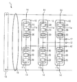
- FIG. 1 shows the construction of a modular power converter 1 which is designed as a modular multilevel converter (M2C). This is designed in this embodiment with three AC-side terminals 12 for connection to a three-phase power grid or to a three-phase load. On the DC side, this modular power converter 1 has a DC voltage connection 13. The DC voltage terminal 13 includes a positive and a negative terminal.
- the phase modules 10 are connected to the connection points 14 with the intermediate circuit 15.
- the intermediate circuit 15 has a busbar with a positive potential and a busbar with a negative potential.
- the phase module 10 comprises a series connection of an upper converter valve 11a and a lower converter valve 11b.
- the individual converter valves 11a and 11b have a series connection of submodules 20, 30.
- the connection point between the upper converter valve 11a and the lower converter valve 11b represents the AC-side terminal 12.
- the phase module 10 has in this embodiment, a provided for linear operation submodule 30 on. With this it is possible to optimize the voltage applied to the AC-side terminal 12 with respect to a reference potential or between two AC-side terminals 12 voltage applied in such a way that the harmonic content of this voltage is eliminated due to the sinusoidal form of the voltage at the AC voltage side terminal. This eliminates the need for a filter to reduce harmonics. It has proved to be positive for the control of currents when between inductance-side terminal 12 and the busbar with positive potential as well as between AC voltage side terminal 12 and busbar with negative potential each inductances are arranged. These are in the FIG. 1 not shown.
- power converter circuit 1 can be extended by the parallel connection of further phase modules 10 to the already existing phase modules 10 by more AC-side terminals 12.
- the submodules 30 provided for linear operation are each arranged in an upper converter valve 11a and in a lower converter valve 11b. It is irrelevant for the operation of the power converter circuit 1 at which position of the series connection of the submodules 20, 30 the submodule 30 provided for the linear operation is located within the series circuit of the power converter valve 11a, 11b.
- each of the two converter valves 11a, 11b in each phase module 10 has a submodule 30 provided for linear operation, which is operated in linear mode during operation of the modular converter, the voltage at the alternating voltage side terminal 12 can be realized with an ideal sinusoidal waveform.
Abstract
Die Erfindung betrifft Verfahren zum Betreiben eines modularen Stromrichters (1) mit einer Vielzahl von Submodulen (20,30), wobei der modulare Stromrichter (1) an mindestens einem wechselspannungsseitigen Anschluss (12) eine Wechselspannung durch Schalthandlungen von Leistungshalbleitern der Submodule (20,30) erzeugt, wobei mindestens ein Submodul (30), das sich zwischen dem wechselspannungsseitigen Anschluss (12) und einem positiven Anschluss eines Zwischenkreises (15) angeordnet ist, und mindestens ein Submodul (30), das sich zwischen dem wechselspannungsseitigen Anschluss und einem negativen Anschluss eines Zwischenkreises (15) angeordnet ist, im Linearbetrieb betrieben werden. Des Weiteren betrifft die Erfindung einen modularen Stromrichter (1) mit einer Vielzahl von Submodulen (20, 30) zur Durchführung des erfindungsgemäßen Verfahrens.The invention relates to a method for operating a modular power converter (1) having a multiplicity of submodules (20, 30), wherein the modular power converter (1) generates an AC voltage at at least one AC-side terminal (12) by switching operations of power semiconductors of the submodules (20, 30 ), wherein at least one submodule (30) disposed between the AC side terminal (12) and a positive terminal of an intermediate circuit (15) and at least one submodule (30) located between the AC side terminal and a negative terminal a DC link (15) is arranged to be operated in linear operation. Furthermore, the invention relates to a modular power converter (1) having a multiplicity of submodules (20, 30) for carrying out the method according to the invention.
Description
Die Erfindung betrifft ein Verfahren zum Betreiben eines modularen Stromrichters mit einer Vielzahl von Submodulen, wobei der modulare Stromrichter an mindestens einem wechselspannungsseitigen Anschluss eine Wechselspannung durch Schalthandlungen von Leistungshalbleitern der Submodule erzeugt.The invention relates to a method for operating a modular power converter having a multiplicity of submodules, wherein the modular power converter generates an AC voltage by switching operations of power semiconductors of the submodules on at least one AC-side connection.
Stromrichter werden dazu verwendet, elektrische Leistung bezüglich Spannungshöhe, Stromhöhe, Frequenz und Phasenlage umzuwandeln. Stromrichter für die Umwandlung von Wechselspannung in Gleichspannung bzw. von Wechselstrom in Gleichstrom werden als Gleichrichter bezeichnet. Demgegenüber bezeichnet man Stromrichter für die Umwandlung von Gleichspannung in Wechselspannung bzw. von Gleichstrom in Wechselstrom als Wechselrichter. Stromrichter für die Umwandlung von Leistungen mit Spannungen/Strömen einer Frequenz in eine andere Frequenz werden als (Frequenz-)Umrichter bezeichnet.Power converters are used to convert electrical power in terms of voltage level, current level, frequency and phase angle. Power converters for the conversion of AC voltage to DC voltage or from AC to DC are referred to as rectifiers. In contrast, one designates converters for the conversion of DC voltage into AC voltage or from DC to AC as an inverter. Power converters for the conversion of power with voltages / currents of one frequency into another frequency are called (frequency) inverters.
Stromrichter werden eingesetzt, um elektrische Maschinen und Motoren gezielt mit elektrischer Energie zu versorgen. Dadurch sind diese elektrische Maschinen und Motoren durch die Stromrichter steuerbar und regelbar. Ein weiteres Anwendungsgebiet ist die Steuerung von Energieflüssen, die Kompensation von Oberschwingungen und das Bereitstellen von Blindleistung in Energieversorgungsnetzen. Darüber hinaus sind Stromrichter an der verlustarmen Übertragung von Energie mittels Hochspannungsgleichstromübertragung (HGÜ) beteiligt.Power converters are used to specifically supply electrical machines and motors with electrical energy. As a result, these electrical machines and motors can be controlled and regulated by the power converters. Another field of application is the control of energy flows, the compensation of harmonics and the provision of reactive power in power grids. In addition, converters are involved in the low-loss transmission of energy by means of high voltage direct current (HVDC) transmission.
Ein Frequenzumrichter mit Spannungszwischenkreis versorgt einen Motor mit einer gepulsten Spannung, die die Grundschwingung der Motorspannung in ihrem Pulsmuster enthält. Die hochfrequenten Anteile in der Spannung erzeugen Ableitströme zur Bezugserde, die als Störströme im System vorhanden sind. Um diese Störströme zu begrenzen, müssen Filterschaltungen, sogenannte EMV-Filter, eingesetzt werden.A voltage source frequency converter supplies a motor with a pulsed voltage which contains the fundamental of the motor voltage in its pulse pattern. The high-frequency components in the voltage generate leakage currents to the reference ground, which are present as interference currents in the system. Around To limit these interference currents, filter circuits, so-called EMC filters must be used.
Nach einem ersten Stand der Technik wird dieses Problem dadurch gelöst, dass der Umrichter als Multilevel-Topologie ausgeführt wird. In einer bevorzugten Ausführungsform wird dabei eine Umrichterphase nicht durch einen einzelnen Halbleiter oder eine Reihenschaltung von Halbleitern ausgeführt, sondern durch eine Anzahl von in Reihe geschalteten Zellen, die auch als Submodule bezeichnet werden. Die Ausgangsspannung der Phase ist dabei davon abhängig, wie viele Zellen des oberen Brückenzweiges und wie viele Zellen des unteren Brückenzweiges zugeschaltet werden. Ein Brückenzweig wird auch als Stromrichterventil bezeichnet. Ein solcher Frequenzumrichter ist aus der
Der Nachteil dieser Ausführungsformen in Bezug auf EMV-Störströme liegt darin, dass auch bei vielen Submodulen noch eine endliche Stufenhöhe verbleibt. Diese kleine Stufenhöhe reduziert zwar die Störströme proportional zur Anzahl der Stufen, zur Einhaltung von EMV-Grenzwerten sind jedoch sehr kleine Störströme gefordert. Um deren Höhe zu unterschreiten, insbesondere ohne zusätzlichen EMV-Filter, sind extrem viele Stufen erforderlich. Um den Störstrom zu halbieren (6dB Reduzierung), ist eine Verdopplung der Stufenanzahl erforderlich, was bei hohen Stufenzahlen einen sehr hohen Aufwand bedeutet.The disadvantage of these embodiments with respect to EMC interference currents is that even with many submodules, a finite step height still remains. Although this small step height reduces the interference currents in proportion to the number of stages, compliance with EMC limit values requires very small interference currents. To fall below their height, especially without additional EMC filter, extremely many steps are required. To halve the interference current (6dB reduction), a doubling of the number of stages is required, which means a very high cost at high levels.
Des Weiteren sind Geräte bekannt, die als Linearverstärker arbeiten und in der Lage sind, am Umrichterausgang eine exakte Sinusspannung bereit zu stellen. Derartige Geräte sind als lineare Netznachbildungen bekannt. Sie bestehen zumeist aus einer Brückenschaltung von MOSFETs. Allerdings werden diese MOSFETs nicht geschaltet, sondern im Linearbetieb angesteuert, wodurch jede beliebige Spannung am Umrichterausgang eingestellt werden kann.Furthermore, devices are known which operate as a linear amplifier and are capable of an exact at the inverter output Sinusoidal voltage ready to provide. Such devices are known as linear network replicas. They usually consist of a bridge circuit of MOSFETs. However, these MOSFETs are not switched, but driven in the linear actuator, whereby any voltage at the inverter output can be adjusted.
Der Vorteil dieser Variante liegt darin, dass die Störströme aufgrund des echt sinusförmigen Verlaufs der Ausgangsspannung minimal sind. Allerdings ist die Verlustleistung dieser Lösung sehr hoch, da an den MOSFETs ständig hohe Spannung anliegt, während sie Strom führen. Deshalb liegt der Wirkungsgrad solcher Geräte unter 30%.The advantage of this variant is that the interference currents due to the true sinusoidal waveform of the output voltage are minimal. However, the power dissipation of this solution is very high, since the MOSFETs constantly high voltage is present while they carry power. Therefore, the efficiency of such devices is less than 30%.
Der Erfindung liegt die Aufgabe zugrunde, ein Verfahren zur Minimierung von Störströmen eines modularen Stromrichters anzugeben, das sowohl geringe Verluste verursacht als auch einfach und zuverlässig durchführbar ist.The invention has for its object to provide a method for minimizing interference currents of a modular power converter, which causes both low losses and is easy and reliable feasible.
Diese Aufgabe wird durch ein Verfahren zum Betreiben eines modularen Stromrichters mit einer Vielzahl von Submodulen, wobei der modulare Stromrichter an mindestens einem wechselspannungsseitigen Anschluss eine Wechselspannung durch Schalthandlungen von Leistungshalbleitern der Submodule erzeugt, dadurch gelöst, dass mindestens ein Submodul, das sich zwischen dem wechselspannungsseitigen Anschluss und einem positiven Anschluss eines Zwischenkreises angeordnet ist, und mindestens ein Submodul, das sich zwischen dem wechselspannungsseitigen Anschluss und einem negativen Anschluss eines Zwischenkreises angeordnet ist, im Linearbetrieb betrieben werden.This object is achieved by a method for operating a modular power converter having a plurality of submodules, wherein the modular power converter generates an AC voltage by switching operations of power semiconductors of the submodules at at least one AC side terminal, characterized in that at least one submodule extending between the AC side terminal and a positive terminal of a DC link, and at least one sub-module arranged between the AC-side terminal and a negative terminal of a DC link are linearly operated.
Diese Aufgabe wird weiter durch einen Modularen Stromrichter mit einer Vielzahl von Submodulen zur Durchführung des Verfahrens nach einem der Ansprüche 1 bis 5 gelöst.This object is further achieved by a modular power converter with a plurality of submodules for carrying out the method according to one of claims 1 to 5.
Der Erfindung liegt die Erkenntnis zugrunde, dass die Minimierung der Störströme dadurch erreicht, dass eineThe invention is based on the finding that the minimization of interference currents achieved by a
Multivevel-Topologie verwendet wird, wobei jedoch zumindest eine der in den Stromrichterventilen in Reihe geschalteten Submodule im Linearbetrieb arbeitet. Damit werden bei einem Stromrichterventile mit n in Reihe geschalteten Zellen der Anteil von (n-1)/n der Ausgangsspannung durch geschalteten Betrieb verlustarm realisiert, während der Anteil von 1/n im Linearbetrieb eingestellt wird.Multi-level topology is used, but at least one of the submodules connected in series in the power converter valves operates in linear mode. Thus, in a converter valves with n series-connected cells, the proportion of (n-1) / n of the output voltage is realized with low loss by switched operation, while the proportion of 1 / n is set in linear mode.
Mit dieser Lösung ist es möglich, wie bei dem Linearverstärker, am wechselspannungsseitigen Anschluss, der den Stromrichterausgang darstellt, jeden beliebigen Spannungswert exakt einzustellen. Da jedoch nur eine Zelle im Linearbetrieb arbeitet, entsteht auch nur in dieser einen Zelle die relativ hohe Verlustleistung. Die Verlustleistung ist deutlich geringer als bei dem Linearverstärker nach Stand der Technik, weil das einzelne Submodul nur einen Bruchteil der Zwischenkreisspannung aufnimmt.With this solution it is possible, as with the linear amplifier, to set exactly any voltage value at the AC-side connection, which represents the converter output. However, since only one cell works in linear mode, the relatively high power loss occurs only in this one cell. The power loss is significantly lower than in the linear amplifier according to the prior art, because the individual submodule receives only a fraction of the DC link voltage.
Das erfindungsgemäße Verfahren kann sowohl für Stromrichter auf der Netzseite als auch auf der Motorseite verwendet werden. Die Erfindung ist anwendbar für Frequenzumrichter, die exakt sinusförmige Ausgangsspannung liefern sollen. Sie ist ebenfalls anwendbar für Linearverstärker, deren Verluste drastisch reduziert werden sollen.The method according to the invention can be used both for power converters on the mains side and on the motor side. The invention is applicable to frequency converters intended to deliver exactly sinusoidal output voltage. It is also applicable to linear amplifiers whose losses are to be drastically reduced.
Vorteilhafte Ausgestaltungen der Erfindung sind in den abhängigen Ansprüchen angegeben.Advantageous embodiments of the invention are specified in the dependent claims.
Bei einer vorteilhaften Ausgestaltungsform werden die im Linearbetrieb betriebenen Submodule derart angesteuert, dass die Spannung am wechselspannungsseitigen Anschluss einen sinusförmigen Zeitverlauf annimmt. Der besondere Vorteil besteht darin, dass der Sinusverlauf für viele Anwendung benötigt wird und in der Vergangenheit durch mehr oder weniger aufwändige und kostenintensive Filterschaltungen realisiert werden musste. Auf diese Filterschaltung kann nun verzichtet werden. Beim Anschluss beispielsweise an ein Energieversorgungsnetz treten aufgrund des guten sinusförmigen Verlaufs der Ausgangsspannung der Stromrichterschaltung keine hochfrequenten störenden Ströme auf. Genauso verhält es sich bei an der Stromrichterschaltung angeschlossenen Lasten. Auch diese sind teilweise empfindlich gegenüber Oberschwingungen, die mit der erfindungsgemäßen Stromrichterschaltung nicht weitestgehend unterdrückt und teilweise komplett beseitigt werden.In an advantageous embodiment, the submodules operated in linear operation are controlled in such a way that the voltage at the AC-side terminal assumes a sinusoidal time characteristic. The particular advantage is that the sine curve is needed for many applications and in the past had to be realized by more or less complex and costly filter circuits. On this filter circuit can now be dispensed with. When connecting for example to a power grid occur due to the good sinusoidal course the output voltage of the converter circuit no high-frequency disturbing currents. The same applies to loads connected to the converter circuit. These are also partially sensitive to harmonics, which are not largely suppressed with the converter circuit according to the invention and partially completely eliminated.
Bei einer weiteren vorteilhaften Ausgestaltungsform wird eine Zuordnung, welches Submodul im Linearbetrieb betrieben wird, nach wiederkehrenden Zeitpunkten durch mindestens ein Kriterium neu vorgenommen. Liegt das Entwicklungsziel darin, alle Submodule gleichartig auszuführen, um z.B. einen hohen Grad an Gleichteiligkeit im Stromrichter zu erreichen, so können abwechselnd verschiedene Submodule linear geregelt werden, um die Verlustleistung der Linearregelung möglichst gleichmäßig auf alle Submodule zu verteilen. Dabei können die wiederkehrenden Zeitpunkte sich aus einer zyklisch sich wiederholenden Überprüfung ergeben. Dabei werden zu bestimmten Zeitpunkten, im gleichen zeitlichen Abstand zueinander Betriebsparameter der Submodule wie beispielsweise die derzeitige Temperatur der Leistungshalbleiter, insbesondere an der Sperrschicht, und/oder die derzeitige oder prognostizierte Verlustleistung als Kriterium herangezogen um eine Entscheidung zu treffen, welches Submodul ab einen bestimmten Zeitpunkt im Linearbetrieb betrieben werden soll. Neben einer zyklischen Überprüfung kann diese auch ereignisgesteuert, beispielsweise durch Überschreiten von Temperaturwerten gesteuert werden.In a further advantageous embodiment, an assignment, which submodule is operated in linear operation, is made anew after recurring times by at least one criterion. If the development goal is to make all submodules similar, e.g. To achieve a high degree of uniformity in the converter, so different submodules can be controlled linearly alternately to distribute the power loss of the linear control as evenly as possible to all submodules. The recurring times can result from a cyclically recurring check. Operating parameters of the submodules, such as the current temperature of the power semiconductors, in particular at the blocking layer, and / or the current or predicted power loss are used as criteria at specific times, at the same time interval, in order to make a decision as to which submodule from a certain point in time to be operated in linear operation. In addition to a cyclical check, this can also be event-controlled, for example controlled by exceeding of temperature values.
Bei einer weiteren vorteilhaften Ausgestaltungsform erfolgt die Zuordnung durch das mindestens eine Kriterium derart, dass die Temperatur und/oder die Verlustleistung der Submodule im zeitlichen Mittel den gleichen Wert annehmen. Ziel der gleichmäßigen Verteilung der Verlustenergie auf alle Submodule ist es, die Erwärmung der Submodule im zeitlichen Mittel gleich zu gestalten, so dass jedes Modul im Betrieb die gleiche Belastung erfährt. Damit ist es möglich das Maximum an Lebensdauer der einzelnen Submodule sicherzustellen. Ein frühzeitiger Ausfall von Modulen wird dadurch vermieden.In a further advantageous embodiment, the assignment is carried out by the at least one criterion in such a way that the temperature and / or the power loss of the submodules assume the same value in the time average. The aim of the uniform distribution of the loss energy to all submodules is to make the heating of the submodules the same over time, so that each module undergoes the same load during operation. This makes it possible the maximum To ensure the lifetime of the individual submodules. An early failure of modules is thereby avoided.
Bei einer weiteren vorteilhaften Ausgestaltungsform wird für die Zuordnung, welches Submodul als nächstes im Linearbetrieb betrieben wird, das Submodul mit niedrigster Temperatur herangezogen. In dieser bevorzugten Ausführungsform kann immer das Submodul Zelle die Linearregelung übernehmen, deren Temperatur die niedrigste ist. Diese Auswahllogik stellt ein einfaches Kriterium für die gleiche thermische Belastung der Submodule dar und trägt zu einer langen Lebensdauer des Stromrichters bei.In a further advantageous embodiment, the submodule with the lowest temperature is used for the assignment, which submodule is next operated in linear mode. In this preferred embodiment, the submodule cell can always adopt the linear control whose temperature is the lowest. This selection logic represents a simple criterion for the same thermal load of the submodules and contributes to a long lifetime of the converter.
Bei einer weiteren vorteilhaften Ausgestaltungsform weist der modulare Stromrichter
- einen Gleichspannungsanschluss,
- mindestens einen wechselspannungsseitigen Anschluss und
- mindestens ein Phasenmodul auf,
wobei eine elektrische Verbindung zwischen dem ersten und dem zweiten Stromrichterventil den wechselspannungsseitigen Anschluss darstellt,
wobei die Anschlüsse des Phasenmoduls mit dem Gleichspannungsanschluss elektrisch verbunden sind,
wobei das erste und das zweite Stromrichterventil jeweils wenigstens zwei Submodule aufweisen, die elektrisch in Reihe angeordnet sind,
wobei die Submodule mindestens einen Kondensator und mindestens einen Leistungshalbleiter aufweisen. Das erfindungsgemäße Verfahren ist insbesondere für den M2C Stromrichter geeignet, der durch die oben genannten Merkmale beschrieben wird. Der Stromrichter eignet sich sowohl für Antriebsanwendungen als auch zum Anschluss an ein Energieversorgungsnetz. Die Submodule des Umrichters werden von einer Regelung angesteuert, die auf einfache Weise auch die Regelung/Steuerung des Linearbetriebs übernehmen kann. Durch die Anwendung des Verfahrens können die Aspekte der idealen Sinusform bei gleichzeitig niedrigen Verlusten auf besonders einfache Weise realisiert werden.In a further advantageous embodiment, the modular power converter
- a DC voltage connection,
- at least one AC-side connection and
- at least one phase module,
wherein an electrical connection between the first and second converter valves represents the AC side terminal,
wherein the terminals of the phase module are electrically connected to the DC voltage terminal,
wherein the first and second power converter valves each have at least two sub-modules arranged electrically in series,
wherein the submodules have at least one capacitor and at least one power semiconductor. The inventive method is particularly suitable for the M2C power converter, which is described by the features mentioned above. The converter is suitable for drive applications as well as for connection to a power supply network. The submodules of the inverter are controlled by a controller, which can easily take over the control of linear operation. By applying the method, aspects of the ideal sinusoidal shape can be added simultaneously low losses can be realized in a particularly simple manner.
Bei einer weiteren vorteilhaften Ausgestaltungsform weist der modulare Stromrichter mindestens ein Submodul auf, das für den Linearbetrieb vorgesehen ist und wobei das für den Linearbetrieb vorgesehene Submodule eine besonders gute Kühlung aufweist. Dieses einzelne, linear geregelte Submodul kann mit besonders guter Kühlung versehen werden, um die relativ hohen Verluste dieser einzelnen Zelle abzuführen. Dies kann beispielsweise durch größere oder leistungsfähigere Kühlkörper realisiert werde. Eine andere Möglichkeit besteht darin, diese am Anfang eines Kühlkreises anzuordnen, bei dem das Kühlmedium wie Luft oder Wasser ohne die Vorerwärmung durch andere Komponenten noch die geringste Temperatur aufweist.In a further advantageous embodiment, the modular power converter has at least one submodule which is provided for linear operation and wherein the submodules provided for linear operation have particularly good cooling. This single, linearly controlled submodule can be provided with particularly good cooling in order to dissipate the relatively high losses of this single cell. This can be realized for example by larger or more powerful heatsink. Another possibility is to arrange them at the beginning of a cooling circuit in which the cooling medium such as air or water without the preheating by other components still has the lowest temperature.
Im Folgenden wird die Erfindung anhand der in den Figuren dargestellten Ausführungsbeispiele näher beschrieben und erläutert. Es zeigt:
- FIG 1
- ein Ausführungsbeispiel eines modularen Stromrichters mit einem für den Linearbetrieb vorgesehenem Submodul pro Stromrichterventil.
- FIG. 1
- An embodiment of a modular converter with a provided for linear operation submodule per converter valve.
Claims (8)
wobei eine elektrische Verbindung zwischen dem oberen und dem unteren Stromrichterventil (11a,11b) den wechselspannungsseitigen Anschluss (12) darstellt,
wobei die Anschlüsse (14) des Phasenmoduls (10) mit dem Gleichspannungsanschluss (13) elektrisch verbunden sind, wobei das obere und das untere Stromrichterventil (11a,11b) jeweils wenigstens zwei Submodule (20,30) aufweisen, die elektrisch in Reihe angeordnet sind,
wobei die Submodule (20,30) mindestens einen Kondensator (42) und mindestens einen Leistungshalbleiter (21) aufweisen.Modular power converter (1) according to claim 6, characterized in that the modular power converter (1)
wherein an electrical connection between the upper and lower power converter valves (11a, 11b) represents the AC side terminal (12),
wherein the terminals (14) of the phase module (10) are electrically connected to the DC terminal (13), the upper and lower converter valves (11a, 11b) each having at least two sub-modules (20, 30) arranged in electrical series .
wherein the submodules (20, 30) have at least one capacitor (42) and at least one power semiconductor (21).
Priority Applications (2)
| Application Number | Priority Date | Filing Date | Title |
|---|---|---|---|
| DK14001185.9T DK2928055T3 (en) | 2014-03-31 | 2014-03-31 | Modular converter and method for generating a sinusoidal output voltage with reduced harmonic vibration content |
| EP14001185.9A EP2928055B1 (en) | 2014-03-31 | 2014-03-31 | Modular power converter and method for generating a sinusoidal output voltage with reduced harmonics |
Applications Claiming Priority (1)
| Application Number | Priority Date | Filing Date | Title |
|---|---|---|---|
| EP14001185.9A EP2928055B1 (en) | 2014-03-31 | 2014-03-31 | Modular power converter and method for generating a sinusoidal output voltage with reduced harmonics |
Publications (2)
| Publication Number | Publication Date |
|---|---|
| EP2928055A1 true EP2928055A1 (en) | 2015-10-07 |
| EP2928055B1 EP2928055B1 (en) | 2019-02-06 |
Family
ID=50439111
Family Applications (1)
| Application Number | Title | Priority Date | Filing Date |
|---|---|---|---|
| EP14001185.9A Active EP2928055B1 (en) | 2014-03-31 | 2014-03-31 | Modular power converter and method for generating a sinusoidal output voltage with reduced harmonics |
Country Status (2)
| Country | Link |
|---|---|
| EP (1) | EP2928055B1 (en) |
| DK (1) | DK2928055T3 (en) |
Cited By (1)
| Publication number | Priority date | Publication date | Assignee | Title |
|---|---|---|---|---|
| DE102019112826B3 (en) | 2019-05-16 | 2020-06-18 | Dr. Ing. H.C. F. Porsche Aktiengesellschaft | Analog-digital module for a modular multilevel converter |
Citations (3)
| Publication number | Priority date | Publication date | Assignee | Title |
|---|---|---|---|---|
| US5886504A (en) * | 1994-09-14 | 1999-03-23 | Coleman Powermate, Inc. | Throttle controlled generator system |
| DE10103031A1 (en) | 2001-01-24 | 2002-07-25 | Rainer Marquardt | Current rectification circuit for voltage source inverters with separate energy stores replaces phase blocks with energy storing capacitors |
| WO2011124260A1 (en) * | 2010-04-08 | 2011-10-13 | Areva T&D Uk Limited | Modularised converter for hvdc and statcom |
-
2014
- 2014-03-31 DK DK14001185.9T patent/DK2928055T3/en active
- 2014-03-31 EP EP14001185.9A patent/EP2928055B1/en active Active
Patent Citations (3)
| Publication number | Priority date | Publication date | Assignee | Title |
|---|---|---|---|---|
| US5886504A (en) * | 1994-09-14 | 1999-03-23 | Coleman Powermate, Inc. | Throttle controlled generator system |
| DE10103031A1 (en) | 2001-01-24 | 2002-07-25 | Rainer Marquardt | Current rectification circuit for voltage source inverters with separate energy stores replaces phase blocks with energy storing capacitors |
| WO2011124260A1 (en) * | 2010-04-08 | 2011-10-13 | Areva T&D Uk Limited | Modularised converter for hvdc and statcom |
Cited By (1)
| Publication number | Priority date | Publication date | Assignee | Title |
|---|---|---|---|---|
| DE102019112826B3 (en) | 2019-05-16 | 2020-06-18 | Dr. Ing. H.C. F. Porsche Aktiengesellschaft | Analog-digital module for a modular multilevel converter |
Also Published As
| Publication number | Publication date |
|---|---|
| DK2928055T3 (en) | 2019-04-23 |
| EP2928055B1 (en) | 2019-02-06 |
Similar Documents
| Publication | Publication Date | Title |
|---|---|---|
| EP3496259B1 (en) | Electrical converter system | |
| EP2596980B1 (en) | Multiple point frequency converter with brake chopper | |
| EP3245727B1 (en) | Converter module for a multi-level energy converter | |
| DE102008014898A1 (en) | Method for controlling a multiphase power converter with distributed energy stores at low output frequencies | |
| WO2002023703A1 (en) | Controlling and regulating method for a three-level power converter having active clamping switches, and a device therefor | |
| EP2654190B1 (en) | Method for operating an electric circuit | |
| EP3211784A1 (en) | Double submodule for a modular multilevel converter and modular multilevel converter comprising same | |
| DE102008036811A1 (en) | Redundancy control method of a multi-phase power converter with distributed energy storage | |
| EP2807738B1 (en) | Multicell converter | |
| WO2014206704A1 (en) | Converter assembly having multi-step converters connected in parallel and method for controlling said multi-step converters | |
| EP2928060A1 (en) | Modular frequency converter circuit with submodules having different switching capacities | |
| DE10140747A1 (en) | Control and regulating method for a three-point converter with active clamp switches and device therefor | |
| WO2017080928A1 (en) | Modular multi-step converter, and method for operating a modular multi-step converter | |
| WO2019063214A1 (en) | Precharging a power converter voltage dc link by means of an auxiliary power supply | |
| EP3095178B1 (en) | Modular power converter circuit with submodules which are operated in linear mode | |
| WO2013023914A1 (en) | Inverter arrangement | |
| EP2928055B1 (en) | Modular power converter and method for generating a sinusoidal output voltage with reduced harmonics | |
| DE102015105889A1 (en) | Switching module and converter with at least one switching module | |
| EP3353885B1 (en) | Method for operating a modular multi-level power converter, modular multi-level power converter, and computer program | |
| DE102013109714A1 (en) | Method for operating an electrical circuit and electrical circuit | |
| EP3331118B1 (en) | System for transmitting electric power | |
| EP2928056B1 (en) | Method and apparatus for operating a modular power converter with adjustable slew rates of the switching operations in the sub-modules | |
| EP1473822B1 (en) | Power converter circuit and method for controlling the same | |
| EP2958225A2 (en) | Method for operating an intermediate voltage circuit having modular multi-stage inverter | |
| DE102020203994A1 (en) | Method for controlling switching elements of a modular multilevel converter |
Legal Events
| Date | Code | Title | Description |
|---|---|---|---|
| PUAI | Public reference made under article 153(3) epc to a published international application that has entered the european phase |
Free format text: ORIGINAL CODE: 0009012 |
|
| AK | Designated contracting states |
Kind code of ref document: A1 Designated state(s): AL AT BE BG CH CY CZ DE DK EE ES FI FR GB GR HR HU IE IS IT LI LT LU LV MC MK MT NL NO PL PT RO RS SE SI SK SM TR |
|
| AX | Request for extension of the european patent |
Extension state: BA ME |
|
| 17P | Request for examination filed |
Effective date: 20160406 |
|
| RBV | Designated contracting states (corrected) |
Designated state(s): AL AT BE BG CH CY CZ DE DK EE ES FI FR GB GR HR HU IE IS IT LI LT LU LV MC MK MT NL NO PL PT RO RS SE SI SK SM TR |
|
| RAP1 | Party data changed (applicant data changed or rights of an application transferred) |
Owner name: SIEMENS AKTIENGESELLSCHAFT |
|
| GRAP | Despatch of communication of intention to grant a patent |
Free format text: ORIGINAL CODE: EPIDOSNIGR1 |
|
| STAA | Information on the status of an ep patent application or granted ep patent |
Free format text: STATUS: GRANT OF PATENT IS INTENDED |
|
| INTG | Intention to grant announced |
Effective date: 20181004 |
|
| GRAS | Grant fee paid |
Free format text: ORIGINAL CODE: EPIDOSNIGR3 |
|
| GRAA | (expected) grant |
Free format text: ORIGINAL CODE: 0009210 |
|
| STAA | Information on the status of an ep patent application or granted ep patent |
Free format text: STATUS: THE PATENT HAS BEEN GRANTED |
|
| AK | Designated contracting states |
Kind code of ref document: B1 Designated state(s): AL AT BE BG CH CY CZ DE DK EE ES FI FR GB GR HR HU IE IS IT LI LT LU LV MC MK MT NL NO PL PT RO RS SE SI SK SM TR |
|
| REG | Reference to a national code |
Ref country code: GB Ref legal event code: FG4D Free format text: NOT ENGLISH |
|
| REG | Reference to a national code |
Ref country code: CH Ref legal event code: EP Ref country code: AT Ref legal event code: REF Ref document number: 1095482 Country of ref document: AT Kind code of ref document: T Effective date: 20190215 |
|
| REG | Reference to a national code |
Ref country code: IE Ref legal event code: FG4D Free format text: LANGUAGE OF EP DOCUMENT: GERMAN |
|
| REG | Reference to a national code |
Ref country code: CH Ref legal event code: NV Representative=s name: SIEMENS SCHWEIZ AG, CH |
|
| REG | Reference to a national code |
Ref country code: DE Ref legal event code: R096 Ref document number: 502014010738 Country of ref document: DE |
|
| REG | Reference to a national code |
Ref country code: DK Ref legal event code: T3 Effective date: 20190415 |
|
| REG | Reference to a national code |
Ref country code: SE Ref legal event code: TRGR |
|
| REG | Reference to a national code |
Ref country code: NL Ref legal event code: MP Effective date: 20190206 |
|
| REG | Reference to a national code |
Ref country code: NO Ref legal event code: T2 Effective date: 20190206 |
|
| REG | Reference to a national code |
Ref country code: LT Ref legal event code: MG4D |
|
| PG25 | Lapsed in a contracting state [announced via postgrant information from national office to epo] |
Ref country code: PT Free format text: LAPSE BECAUSE OF FAILURE TO SUBMIT A TRANSLATION OF THE DESCRIPTION OR TO PAY THE FEE WITHIN THE PRESCRIBED TIME-LIMIT Effective date: 20190606 Ref country code: LT Free format text: LAPSE BECAUSE OF FAILURE TO SUBMIT A TRANSLATION OF THE DESCRIPTION OR TO PAY THE FEE WITHIN THE PRESCRIBED TIME-LIMIT Effective date: 20190206 Ref country code: NL Free format text: LAPSE BECAUSE OF FAILURE TO SUBMIT A TRANSLATION OF THE DESCRIPTION OR TO PAY THE FEE WITHIN THE PRESCRIBED TIME-LIMIT Effective date: 20190206 |
|
| PG25 | Lapsed in a contracting state [announced via postgrant information from national office to epo] |
Ref country code: RS Free format text: LAPSE BECAUSE OF FAILURE TO SUBMIT A TRANSLATION OF THE DESCRIPTION OR TO PAY THE FEE WITHIN THE PRESCRIBED TIME-LIMIT Effective date: 20190206 Ref country code: LV Free format text: LAPSE BECAUSE OF FAILURE TO SUBMIT A TRANSLATION OF THE DESCRIPTION OR TO PAY THE FEE WITHIN THE PRESCRIBED TIME-LIMIT Effective date: 20190206 Ref country code: GR Free format text: LAPSE BECAUSE OF FAILURE TO SUBMIT A TRANSLATION OF THE DESCRIPTION OR TO PAY THE FEE WITHIN THE PRESCRIBED TIME-LIMIT Effective date: 20190507 Ref country code: HR Free format text: LAPSE BECAUSE OF FAILURE TO SUBMIT A TRANSLATION OF THE DESCRIPTION OR TO PAY THE FEE WITHIN THE PRESCRIBED TIME-LIMIT Effective date: 20190206 Ref country code: IS Free format text: LAPSE BECAUSE OF FAILURE TO SUBMIT A TRANSLATION OF THE DESCRIPTION OR TO PAY THE FEE WITHIN THE PRESCRIBED TIME-LIMIT Effective date: 20190606 Ref country code: BG Free format text: LAPSE BECAUSE OF FAILURE TO SUBMIT A TRANSLATION OF THE DESCRIPTION OR TO PAY THE FEE WITHIN THE PRESCRIBED TIME-LIMIT Effective date: 20190506 |
|
| PG25 | Lapsed in a contracting state [announced via postgrant information from national office to epo] |
Ref country code: EE Free format text: LAPSE BECAUSE OF FAILURE TO SUBMIT A TRANSLATION OF THE DESCRIPTION OR TO PAY THE FEE WITHIN THE PRESCRIBED TIME-LIMIT Effective date: 20190206 Ref country code: CZ Free format text: LAPSE BECAUSE OF FAILURE TO SUBMIT A TRANSLATION OF THE DESCRIPTION OR TO PAY THE FEE WITHIN THE PRESCRIBED TIME-LIMIT Effective date: 20190206 Ref country code: RO Free format text: LAPSE BECAUSE OF FAILURE TO SUBMIT A TRANSLATION OF THE DESCRIPTION OR TO PAY THE FEE WITHIN THE PRESCRIBED TIME-LIMIT Effective date: 20190206 Ref country code: ES Free format text: LAPSE BECAUSE OF FAILURE TO SUBMIT A TRANSLATION OF THE DESCRIPTION OR TO PAY THE FEE WITHIN THE PRESCRIBED TIME-LIMIT Effective date: 20190206 Ref country code: SK Free format text: LAPSE BECAUSE OF FAILURE TO SUBMIT A TRANSLATION OF THE DESCRIPTION OR TO PAY THE FEE WITHIN THE PRESCRIBED TIME-LIMIT Effective date: 20190206 Ref country code: AL Free format text: LAPSE BECAUSE OF FAILURE TO SUBMIT A TRANSLATION OF THE DESCRIPTION OR TO PAY THE FEE WITHIN THE PRESCRIBED TIME-LIMIT Effective date: 20190206 |
|
| REG | Reference to a national code |
Ref country code: DE Ref legal event code: R097 Ref document number: 502014010738 Country of ref document: DE |
|
| PG25 | Lapsed in a contracting state [announced via postgrant information from national office to epo] |
Ref country code: LU Free format text: LAPSE BECAUSE OF NON-PAYMENT OF DUE FEES Effective date: 20190331 Ref country code: PL Free format text: LAPSE BECAUSE OF FAILURE TO SUBMIT A TRANSLATION OF THE DESCRIPTION OR TO PAY THE FEE WITHIN THE PRESCRIBED TIME-LIMIT Effective date: 20190206 Ref country code: SM Free format text: LAPSE BECAUSE OF FAILURE TO SUBMIT A TRANSLATION OF THE DESCRIPTION OR TO PAY THE FEE WITHIN THE PRESCRIBED TIME-LIMIT Effective date: 20190206 |
|
| REG | Reference to a national code |
Ref country code: BE Ref legal event code: MM Effective date: 20190331 |
|
| PLBE | No opposition filed within time limit |
Free format text: ORIGINAL CODE: 0009261 |
|
| STAA | Information on the status of an ep patent application or granted ep patent |
Free format text: STATUS: NO OPPOSITION FILED WITHIN TIME LIMIT |
|
| PG25 | Lapsed in a contracting state [announced via postgrant information from national office to epo] |
Ref country code: MC Free format text: LAPSE BECAUSE OF FAILURE TO SUBMIT A TRANSLATION OF THE DESCRIPTION OR TO PAY THE FEE WITHIN THE PRESCRIBED TIME-LIMIT Effective date: 20190206 |
|
| 26N | No opposition filed |
Effective date: 20191107 |
|
| PG25 | Lapsed in a contracting state [announced via postgrant information from national office to epo] |
Ref country code: IE Free format text: LAPSE BECAUSE OF NON-PAYMENT OF DUE FEES Effective date: 20190331 |
|
| PG25 | Lapsed in a contracting state [announced via postgrant information from national office to epo] |
Ref country code: BE Free format text: LAPSE BECAUSE OF NON-PAYMENT OF DUE FEES Effective date: 20190331 Ref country code: SI Free format text: LAPSE BECAUSE OF FAILURE TO SUBMIT A TRANSLATION OF THE DESCRIPTION OR TO PAY THE FEE WITHIN THE PRESCRIBED TIME-LIMIT Effective date: 20190206 |
|
| PG25 | Lapsed in a contracting state [announced via postgrant information from national office to epo] |
Ref country code: TR Free format text: LAPSE BECAUSE OF FAILURE TO SUBMIT A TRANSLATION OF THE DESCRIPTION OR TO PAY THE FEE WITHIN THE PRESCRIBED TIME-LIMIT Effective date: 20190206 |
|
| PGFP | Annual fee paid to national office [announced via postgrant information from national office to epo] |
Ref country code: DK Payment date: 20200324 Year of fee payment: 7 Ref country code: IT Payment date: 20200326 Year of fee payment: 7 Ref country code: SE Payment date: 20200317 Year of fee payment: 7 Ref country code: GB Payment date: 20200311 Year of fee payment: 7 |
|
| PG25 | Lapsed in a contracting state [announced via postgrant information from national office to epo] |
Ref country code: MT Free format text: LAPSE BECAUSE OF FAILURE TO SUBMIT A TRANSLATION OF THE DESCRIPTION OR TO PAY THE FEE WITHIN THE PRESCRIBED TIME-LIMIT Effective date: 20190206 |
|
| PGFP | Annual fee paid to national office [announced via postgrant information from national office to epo] |
Ref country code: FR Payment date: 20200316 Year of fee payment: 7 |
|
| PGFP | Annual fee paid to national office [announced via postgrant information from national office to epo] |
Ref country code: CH Payment date: 20200602 Year of fee payment: 7 |
|
| REG | Reference to a national code |
Ref country code: AT Ref legal event code: MM01 Ref document number: 1095482 Country of ref document: AT Kind code of ref document: T Effective date: 20190331 |
|
| REG | Reference to a national code |
Ref country code: FI Ref legal event code: MAE |
|
| PG25 | Lapsed in a contracting state [announced via postgrant information from national office to epo] |
Ref country code: FI Free format text: LAPSE BECAUSE OF NON-PAYMENT OF DUE FEES Effective date: 20200331 |
|
| PG25 | Lapsed in a contracting state [announced via postgrant information from national office to epo] |
Ref country code: AT Free format text: LAPSE BECAUSE OF NON-PAYMENT OF DUE FEES Effective date: 20190331 |
|
| PG25 | Lapsed in a contracting state [announced via postgrant information from national office to epo] |
Ref country code: CY Free format text: LAPSE BECAUSE OF FAILURE TO SUBMIT A TRANSLATION OF THE DESCRIPTION OR TO PAY THE FEE WITHIN THE PRESCRIBED TIME-LIMIT Effective date: 20190206 |
|
| PG25 | Lapsed in a contracting state [announced via postgrant information from national office to epo] |
Ref country code: HU Free format text: LAPSE BECAUSE OF FAILURE TO SUBMIT A TRANSLATION OF THE DESCRIPTION OR TO PAY THE FEE WITHIN THE PRESCRIBED TIME-LIMIT; INVALID AB INITIO Effective date: 20140331 |
|
| REG | Reference to a national code |
Ref country code: CH Ref legal event code: PL |
|
| REG | Reference to a national code |
Ref country code: DK Ref legal event code: EBP Effective date: 20210331 |
|
| GBPC | Gb: european patent ceased through non-payment of renewal fee |
Effective date: 20210331 |
|
| REG | Reference to a national code |
Ref country code: SE Ref legal event code: EUG |
|
| PG25 | Lapsed in a contracting state [announced via postgrant information from national office to epo] |
Ref country code: GB Free format text: LAPSE BECAUSE OF NON-PAYMENT OF DUE FEES Effective date: 20210331 Ref country code: FR Free format text: LAPSE BECAUSE OF NON-PAYMENT OF DUE FEES Effective date: 20210331 Ref country code: SE Free format text: LAPSE BECAUSE OF NON-PAYMENT OF DUE FEES Effective date: 20210401 Ref country code: LI Free format text: LAPSE BECAUSE OF NON-PAYMENT OF DUE FEES Effective date: 20210331 Ref country code: CH Free format text: LAPSE BECAUSE OF NON-PAYMENT OF DUE FEES Effective date: 20210331 |
|
| PG25 | Lapsed in a contracting state [announced via postgrant information from national office to epo] |
Ref country code: IT Free format text: LAPSE BECAUSE OF NON-PAYMENT OF DUE FEES Effective date: 20210331 Ref country code: DK Free format text: LAPSE BECAUSE OF NON-PAYMENT OF DUE FEES Effective date: 20210331 |
|
| PG25 | Lapsed in a contracting state [announced via postgrant information from national office to epo] |
Ref country code: MK Free format text: LAPSE BECAUSE OF FAILURE TO SUBMIT A TRANSLATION OF THE DESCRIPTION OR TO PAY THE FEE WITHIN THE PRESCRIBED TIME-LIMIT Effective date: 20190206 |
|
| PGFP | Annual fee paid to national office [announced via postgrant information from national office to epo] |
Ref country code: NO Payment date: 20230308 Year of fee payment: 10 |
|
| P01 | Opt-out of the competence of the unified patent court (upc) registered |
Effective date: 20230512 |
|
| PGFP | Annual fee paid to national office [announced via postgrant information from national office to epo] |
Ref country code: DE Payment date: 20230519 Year of fee payment: 10 |
|
| REG | Reference to a national code |
Ref country code: DE Ref legal event code: R081 Ref document number: 502014010738 Country of ref document: DE Owner name: INNOMOTICS GMBH, DE Free format text: FORMER OWNER: SIEMENS AKTIENGESELLSCHAFT, 80333 MUENCHEN, DE |
|
| REG | Reference to a national code |
Ref country code: NO Ref legal event code: CHAD Owner name: LNNOMOTICS GMBH, DE |