EP2958225A2 - Method for operating an intermediate voltage circuit having modular multi-stage inverter - Google Patents
Method for operating an intermediate voltage circuit having modular multi-stage inverter Download PDFInfo
- Publication number
- EP2958225A2 EP2958225A2 EP15169194.6A EP15169194A EP2958225A2 EP 2958225 A2 EP2958225 A2 EP 2958225A2 EP 15169194 A EP15169194 A EP 15169194A EP 2958225 A2 EP2958225 A2 EP 2958225A2
- Authority
- EP
- European Patent Office
- Prior art keywords
- voltage
- power converter
- energy storage
- storage means
- phase
- Prior art date
- Legal status (The legal status is an assumption and is not a legal conclusion. Google has not performed a legal analysis and makes no representation as to the accuracy of the status listed.)
- Withdrawn
Links
Images

Classifications
-
- H—ELECTRICITY
- H02—GENERATION; CONVERSION OR DISTRIBUTION OF ELECTRIC POWER
- H02M—APPARATUS FOR CONVERSION BETWEEN AC AND AC, BETWEEN AC AND DC, OR BETWEEN DC AND DC, AND FOR USE WITH MAINS OR SIMILAR POWER SUPPLY SYSTEMS; CONVERSION OF DC OR AC INPUT POWER INTO SURGE OUTPUT POWER; CONTROL OR REGULATION THEREOF
- H02M7/00—Conversion of ac power input into dc power output; Conversion of dc power input into ac power output
- H02M7/42—Conversion of dc power input into ac power output without possibility of reversal
- H02M7/44—Conversion of dc power input into ac power output without possibility of reversal by static converters
- H02M7/48—Conversion of dc power input into ac power output without possibility of reversal by static converters using discharge tubes with control electrode or semiconductor devices with control electrode
- H02M7/483—Converters with outputs that each can have more than two voltages levels
- H02M7/4835—Converters with outputs that each can have more than two voltages levels comprising two or more cells, each including a switchable capacitor, the capacitors having a nominal charge voltage which corresponds to a given fraction of the input voltage, and the capacitors being selectively connected in series to determine the instantaneous output voltage
-
- H—ELECTRICITY
- H02—GENERATION; CONVERSION OR DISTRIBUTION OF ELECTRIC POWER
- H02M—APPARATUS FOR CONVERSION BETWEEN AC AND AC, BETWEEN AC AND DC, OR BETWEEN DC AND DC, AND FOR USE WITH MAINS OR SIMILAR POWER SUPPLY SYSTEMS; CONVERSION OF DC OR AC INPUT POWER INTO SURGE OUTPUT POWER; CONTROL OR REGULATION THEREOF
- H02M7/00—Conversion of ac power input into dc power output; Conversion of dc power input into ac power output
- H02M7/42—Conversion of dc power input into ac power output without possibility of reversal
- H02M7/44—Conversion of dc power input into ac power output without possibility of reversal by static converters
- H02M7/48—Conversion of dc power input into ac power output without possibility of reversal by static converters using discharge tubes with control electrode or semiconductor devices with control electrode
- H02M7/53—Conversion of dc power input into ac power output without possibility of reversal by static converters using discharge tubes with control electrode or semiconductor devices with control electrode using devices of a triode or transistor type requiring continuous application of a control signal
- H02M7/537—Conversion of dc power input into ac power output without possibility of reversal by static converters using discharge tubes with control electrode or semiconductor devices with control electrode using devices of a triode or transistor type requiring continuous application of a control signal using semiconductor devices only, e.g. single switched pulse inverters
- H02M7/539—Conversion of dc power input into ac power output without possibility of reversal by static converters using discharge tubes with control electrode or semiconductor devices with control electrode using devices of a triode or transistor type requiring continuous application of a control signal using semiconductor devices only, e.g. single switched pulse inverters with automatic control of output wave form or frequency
- H02M7/5395—Conversion of dc power input into ac power output without possibility of reversal by static converters using discharge tubes with control electrode or semiconductor devices with control electrode using devices of a triode or transistor type requiring continuous application of a control signal using semiconductor devices only, e.g. single switched pulse inverters with automatic control of output wave form or frequency by pulse-width modulation
Definitions
- the invention relates to a method for operating a voltage intermediate circuit having a modular multistage converter having a plurality of converter modules, each converter module comprises a series circuit of submodules and each submodule is associated with a voltage interval and switching elements and an energy storage means, wherein a power converter module to increase the headroom one Shifting voltage between zero points of the modular multi-stage converter on the AC voltage and the DC side generating zero system voltage is switched.
- Such a modular multistage power converter is also referred to as a modular multilevel power converter (MMC).
- MMC modular multilevel power converter
- the submodules which are also referred to as phase elements, each comprise an arrangement of switching elements which each have at least two turn-off power semiconductors and at least two freewheeling diodes and energy storage means connected in parallel thereto.
- WO 2007/028349 A1 is a modular multi-stage power converter with multiple power converter modules known.
- Such devices have, for example, two rectifiers connected on the DC side in order to transmit electrical energy between two electrically separate AC voltage networks and to control this transmission in a targeted manner. Such a control is necessary because in AC networks local overloads or unequal load distributions may occur. These overloads can be compensated by the regulated energy transfer.
- HVDC high-voltage DC transmission
- VSC Voltage Source Converter
- an energy storage means eg. As a capacitor needed.
- Such an HVDC system usually comprises a first converter as a converter for converting the AC voltage into a DC voltage, a transmission cable as a DC voltage line and a second converter as a converter for converting the DC voltage into an AC voltage.
- a power converter comprises a plurality of branches, wherein an upper and a lower branch together form a phase module, which is also referred to as a converter phase.
- phase module comprises a plurality of submodules arranged in series with switching elements, wherein a switching element has two power semiconductors, two diodes and a capacitor as energy storage means.
- the power semiconductors are electronic switches, z. IGBTs.
- WO 2007/028349 A1 is described as an example of a power converter, a H-circuit, which is used in an HVDC system.
- the maximum realizable amplitude of the AC output voltage through the intermediate circuit voltage of the central energy storage means, the z. B. may be formed as a storage capacitor determined.
- the ratio of the sum voltage of the energy storage means to the amplitude of the module voltage of the associated power converter module is called the degree of duty for which an upper limit exists.
- a zero system voltage also referred to as a zero system
- a zero system is a voltage shift between the natural zero points of a converter on the AC and DC sides, increasing the duty cycle.
- the invention is therefore based on the object to provide a method for operating a voltage intermediate circuit having a modular multistage power converter, in which permanently a control reserve is present.
- amplitude and phase of the output voltage of a power converter module by means of the zero system voltage can be chosen so that the largest possible control reserve is obtained taking into account the voltage of the energy storage means.
- the application of a zero system voltage causes a voltage shift between the zero point of the MMC and the voltages on the AC side of the multi-stage converter, thereby allowing an increase in the headroom.
- the amplitude and phase position of the output voltage of a converter module are selected by means of the zero system so that there is sufficient reserve reserve at all times. This means that the over time changing voltage of the energy storage means is always higher than the output voltage of a power converter module, so that a transfer of energy from the energy storage means to the or the converter modules is possible.
- the invention provides the advantage that with a constant headroom, the number of submodules can be reduced. Alternatively or additionally, the size of the energy storage means can be reduced.
- the time profile of the voltage of the energy storage means is taken into account, whereby the drive reserve can be further increased, while in a conventional method only the amplitude of the output voltage with respect to the zero point of the power converter is minimized.
- the sum of the voltages of all energy storage means of a power converter module is preferably taken into account.
- the disadvantage of the conventional method is eliminated by the method according to the invention by modifying the output voltage of the multistage converter by means of the connected zero system voltage such that there is always a maximum possible voltage difference, and thus a maximum possible drive reserve can be achieved at any time.
- a capacitor is used as energy storage means.
- the voltages of the energy storage means of all six converter modules are shifted, ie, for example, the voltages of the six capacitors are shifted.
- a zero system voltage based on the 3rd harmonic is applied.
- any other zero system can also be activated.
- a zero system voltage based on the 3rd harmonic is particularly well suited for reducing the harmonic content.
- a zero system voltage based on balanced sine modulation can be applied.
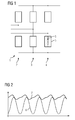
- Fig. 1 shows a conventional modular multi-stage power converter 1, which is provided for a three-phase AC power network and three phase modules 2, 3, 4, which are also referred to as power converter modules.
- Each phase module is connected to one phase of the AC voltage network.
- the phase modules 2, 3, 4 comprise a total of six converter modules 5, each having a plurality of serially connected submodules 6, each associated with a voltage interval.
- Each submodule 6 has switching elements and an energy storage device.
- the conventional modular multistage power converter in this case comprises six single-phase converters with a power converter module for each upper and lower branch.
- Fig. 2 the course of the module voltage of a single conventional power converter module is shown, of which, as already mentioned six are present, between each of which a phase difference is present.
- Fig. 3 shows the voltage curves of all six converter modules of the multi-stage converter.
- the course of the voltage 7 of an energy storage means is shown, which is formed in the illustrated embodiment as a capacitor.
- the time is plotted on the horizontal axis and the voltage of the phase of a converter module is plotted on the vertical axis.
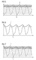
- Fig. 4 and 5 are similar diagrams like that Fig. 2 and 3 and show the time characteristic of the voltage of an energy storage means designated by the reference numeral 9 and the time profile of the voltage of a power converter module designated by the reference numeral 10 when carrying out the method.
- Fig. 5 shows the time course of the voltages of all six converter modules.
- the multistage power converter has a zero system, that is, a zero system voltage, based on the 3rd harmonic.
- the six voltages of the converter modules serve as input variables when calculating the zero system. After calculating the zero-sequence voltage, this is applied to the fundamental oscillation, ie the basic oscillation is superimposed.
- the 6 and 7 show an embodiment of the method for operating the multi-stage converter, in which a balanced sine-modulation based zero system is switched. Symmetrical sine modulation is also referred to as space vector modulation. From the current voltages, a correction system is formed as the -0.5 times the sum of the largest and smallest voltage value. This zero system is then added to the voltages, resulting in the in the 6 and 7 shown voltage curves.
- the reference numeral 11 denotes the Voltage of the energy storage means, the reference numeral 12, the course of a voltage of a power converter module.
- Fig. 7 shows the curves of all six voltages 12 of the converter modules.
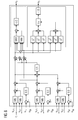
- Fig. 8 is a diagram and shows schematically the calculation of the zero system, where both variants described, ie both in the Fig. 4 and 5 shown superimposition of a based on the 3rd harmonic zero system as well as in the 6 and 7 shown superimposition of a symmetrical sine modulation based zero system are included.
- the six voltages of the converter modules of the basic system are used as input variables, whereby a positive value and a negative value are taken into account.
- the calculation of the zero system based on symmetrical sine modulation is shown on the top right, and the calculation of the third system based on the third harmonic is shown on the bottom right.
Abstract
Verfahren zum Betreiben eines einen Spannungszwischenkreis aufweisenden modularen Mehrstufenstromrichters, der mehrere Stromrichtermodule aufweist, wobei jedes Stromrichtermodul eine Reihenschaltung von Submodulen aufweist und jedes Submodul einem Spannungsintervall zugeordnet ist und Schaltelemente und ein Energiespeichermittel aufweist, wobei einem Stromrichtermodul zur Vergrößerung der Aussteuerreserve eine eine Spannungsverschiebung zwischen Nullpunkten des modularen Mehrstufenstromrichters auf der Wechselspannungs- und der Gleichspannungsseite erzeugende Nullsystemspannung aufgeschaltet wird, dadurch gekennzeichnet, dass Amplitude und Phasenlage der Ausgangsspannung eines Stromrichtermoduls mittels der Nullsystemspannung so gewählt werden, dass unter Berücksichtigung der Spannung der Energiespeichermittel eine möglichst große Aussteuerreserve erhalten wird.A method for operating a multilevel modular multistage power converter having multiple power converter modules, each power converter module having a series connection of submodules and each submodule being associated with a voltage interval and having switching elements and an energy storage means, wherein a power converter module for increasing the headroom has a voltage shift between zero points Modular multi-stage converter on the AC voltage and the DC voltage side generating zero system voltage is switched, characterized in that the amplitude and phase of the output voltage of a power converter module by means of the zero system voltage are chosen so that taking into account the voltage of the energy storage means the largest possible control reserve is obtained.
Description
Die Erfindung betrifft ein Verfahren zum Betreiben eines einen Spannungszwischenkreis aufweisenden modularen Mehrstufenstromrichters, der mehrere Stromrichtermodule aufweist, wobei jedes Stromrichtermodul eine Reihenschaltung von Submodulen aufweist und jedes Submodul einem Spannungsintervall zugeordnet ist und Schaltelemente und ein Energiespeichermittel aufweist, wobei einem Stromrichtermodul zur Vergrößerung der Aussteuerreserve eine eine Spannungsverschiebung zwischen Nullpunkten des modularen Mehrstufenstromrichters auf der Wechselspannungs- und der Gleichspannungsseite erzeugende Nullsystemspannung aufgeschaltet wird.The invention relates to a method for operating a voltage intermediate circuit having a modular multistage converter having a plurality of converter modules, each converter module comprises a series circuit of submodules and each submodule is associated with a voltage interval and switching elements and an energy storage means, wherein a power converter module to increase the headroom one Shifting voltage between zero points of the modular multi-stage converter on the AC voltage and the DC side generating zero system voltage is switched.
Ein derartiger modularer Mehrstufenstromrichter wird auch als Modularer Multilevel Stromrichter (modular multilevel converter, MMC) bezeichnet.Such a modular multistage power converter is also referred to as a modular multilevel power converter (MMC).
Üblicherweise umfassen die Submodule, die auch als Phasenelemente bezeichnet werden, jeweils eine Anordnung von Schaltelementen, die jeweils mindestens zwei abschaltbare Leistungshalbleiter und mindestens zwei jeweils dazu parallel geschaltete Freilaufdioden und Energiespeichermittel aufweisen.Usually, the submodules, which are also referred to as phase elements, each comprise an arrangement of switching elements which each have at least two turn-off power semiconductors and at least two freewheeling diodes and energy storage means connected in parallel thereto.
Aus der
Bei Mehrstufenstromrichtern mit Spannungszwischenkreis wird die maximal realisierbare Amplitude der Ausgangswechselspannung durch die Zwischenkreisspannung des zentralen Energiespeichermittels, das z. B. als Speicherkondensator ausgebildet sein kann, bestimmt. Das Verhältnis der Summenspannung der Energiespeichermittel zu der Amplitude der Modulspannung des zugehörigen Stromrichtermoduls wird Aussteuergrad genannt, für den eine obere Grenze existiert.In multi-stage converters with voltage intermediate circuit, the maximum realizable amplitude of the AC output voltage through the intermediate circuit voltage of the central energy storage means, the z. B. may be formed as a storage capacitor determined. The ratio of the sum voltage of the energy storage means to the amplitude of the module voltage of the associated power converter module is called the degree of duty for which an upper limit exists.
Es ist bereits bekannt, bei Stromrichtern den Aussteuergrad zu erhöhen, indem eine Nullsystemspannung aufgeschaltet wird. Eine Nullsystemspannung, die auch als Nullsystem bezeichnet wird, ist eine Spannungsverschiebung zwischen den natürlichen Nullpunkten eines Stromrichters auf der Wechselspannungs- und der Gleichspannungsseite, wodurch der Aussteuergrad erhöht wird. Ein Nullsystem, das z. B. drei Phasen aufweist, kann durch die Gleichung u0(t)=(u1(t)+u2(t)+u3(t))/3 ausgedrückt werden.It is already known to increase the Aussteuergrad at converters by a zero system voltage is switched. A zero system voltage, also referred to as a zero system, is a voltage shift between the natural zero points of a converter on the AC and DC sides, increasing the duty cycle. A zero system, the z. B. has three phases can be expressed by the equation u 0 (t) = (u 1 (t) + u 2 (t) + u 3 (t)) / 3.
Allerdings kann in der Praxis beim Aufschalten eines Nullsystems das Problem auftreten, dass die zum Schalten zur Verfügung stehende Kondensatorspannung kleiner als die momentane Zweigspannung des Stromrichtermoduls ist, sodass dieser übersteuert wird. Dementsprechend ist der Aussteuergrad in diesen Fällen begrenzt. Um diesen Nachteil zu beseitigen, müsste eine größere Anzahl von Stromrichtermodulen eingesetzt oder die Größe der Energiespeichermittel erhöht werden. Allerdings führen beide Maßnahmen zu erhöhten Kosten.However, in practice when connecting a zero system, the problem may arise that the capacitor voltage available for switching is smaller than the instantaneous branch voltage of the converter module, so that it is overdriven. Accordingly, the Aussteuergrad is limited in these cases. In order to eliminate this disadvantage, a larger number of power converter modules would have to be used or the size of the energy storage means would have to be increased. However, both measures lead to increased costs.
Der Erfindung liegt daher die Aufgabe zugrunde, ein Verfahren zum Betreiben eines einen Spannungszwischenkreis aufweisenden modularen Mehrstufenstromrichters anzugeben, bei dem permanent eine Aussteuerreserve vorhanden ist.The invention is therefore based on the object to provide a method for operating a voltage intermediate circuit having a modular multistage power converter, in which permanently a control reserve is present.
Zur Lösung dieser Aufgabe ist bei einem Verfahren der eingangs genannten Art erfindungsgemäß vorgesehen, dass Amplitude und Phasenlage der Ausgangsspannung eines Stromrichtermoduls mittels der Nullsystemspannung so gewählt werden, dass unter Berücksichtigung der Spannung der Energiespeichermittel eine möglichst große Aussteuerreserve erhalten wird.To solve this problem, it is provided according to the invention in a method of the type mentioned that amplitude and phase of the output voltage of a power converter module by means of the zero system voltage can be chosen so that the largest possible control reserve is obtained taking into account the voltage of the energy storage means.
Das Aufschalten einer Nullsystemspannung bewirkt eine Spannungsverschiebung zwischen dem Nullpunkt des MMC und den Spannungen auf der Wechselspannungsseite des Mehrstufenstromrichters, wodurch eine Erhöhung der Aussteuerreserve ermöglicht wird. Bei dem erfindungsgemäßen Verfahren werden Amplitude und Phasenlage der Ausgangsspannung eines Stromrichtermoduls mittels des Nullsystems so gewählt, dass jederzeit eine genügende Stellreserve vorhanden ist. Das bedeutet, dass die sich im Zeitverlauf ändernde Spannung der Energiespeichermittel stets höher als die Ausgangsspannung eines Stromrichtermoduls ist, sodass eine Energieübertragung von den Energiespeichermitteln an das bzw. die Stromrichtermodule möglich ist.The application of a zero system voltage causes a voltage shift between the zero point of the MMC and the voltages on the AC side of the multi-stage converter, thereby allowing an increase in the headroom. In the method according to the invention, the amplitude and phase position of the output voltage of a converter module are selected by means of the zero system so that there is sufficient reserve reserve at all times. This means that the over time changing voltage of the energy storage means is always higher than the output voltage of a power converter module, so that a transfer of energy from the energy storage means to the or the converter modules is possible.
Durch die Erfindung ergibt sich der Vorteil, dass bei gleich bleibender Aussteuerreserve die Anzahl der Submodule reduziert werden kann. Alternativ oder zusätzlich kann die Größe der Energiespeichermittel verringert werden.The invention provides the advantage that with a constant headroom, the number of submodules can be reduced. Alternatively or additionally, the size of the energy storage means can be reduced.
Bei dem erfindungsgemäßen Verfahren wird der zeitliche Verlauf der Spannung des Energiespeichermittels berücksichtigt, wodurch die Aussteuerreserve weiter erhöht werden kann, während bei einem herkömmlichen Verfahren nur die Amplitude der Ausgangsspannung gegenüber dem Nullpunkt des Stromrichters minimiert wird.In the method according to the invention, the time profile of the voltage of the energy storage means is taken into account, whereby the drive reserve can be further increased, while in a conventional method only the amplitude of the output voltage with respect to the zero point of the power converter is minimized.
Vorzugsweise wird beim Festlegen von Amplitude und Phasenlage der Ausgangsspannung eines Stromrichtermoduls die Summe der Spannungen aller Energiespeichermittel eines Stromrichtermoduls berücksichtigt.When determining the amplitude and phase position of the output voltage of a power converter module, the sum of the voltages of all energy storage means of a power converter module is preferably taken into account.
Der Nachteil des herkömmlichen Verfahrens wird durch das erfindungsgemäße Verfahren beseitigt, indem die Ausgangsspannung des Mehrstufenstromrichters mittels der aufgeschalteten Nullsystemspannung so modifiziert wird, dass stets eine maximal mögliche Spannungsdifferenz vorhanden ist, und somit zu jedem Zeitpunkt eine maximal mögliche Aussteuerreserve erreicht werden kann.The disadvantage of the conventional method is eliminated by the method according to the invention by modifying the output voltage of the multistage converter by means of the connected zero system voltage such that there is always a maximum possible voltage difference, and thus a maximum possible drive reserve can be achieved at any time.
Bei dem erfindungsgemäßen Verfahren wird es bevorzugt, dass ein Kondensator als Energiespeichermittel verwendet wird.In the method according to the invention it is preferred that a capacitor is used as energy storage means.
Es liegt auch im Rahmen der Erfindung, dass bei dem Verfahren ein modularer Mehrstufenstromrichter mit drei Phasenmodulen und sechs Stromrichtermodulen, die auch als Konvertermodule bezeichnet werden, zum Einsatz kommt.It is also within the scope of the invention that in the method a modular multi-stage power converter with three phase modules and six power converter modules, which are also referred to as converter modules, is used.
Vorzugsweise werden erfindungsgemäß die Spannungen der Energiespeichermittel aller sechs Stromrichtermodule (Konvertermodule) verschoben, d.h. beispielsweise werden die Spannungen der sechs Kondensatoren verschoben.Preferably, according to the invention, the voltages of the energy storage means of all six converter modules (converter modules) are shifted, ie, for example, the voltages of the six capacitors are shifted.
Gemäß einer bevorzugten Ausgestaltung des erfindungsgemäßen Verfahrens wird eine auf der 3. Oberschwingung basierende Nullsystemspannung aufgeschaltet. Grundsätzlich kann jedoch auch ein beliebiges anderes Nullsystem aufgeschaltet werden. Im Rahmen der Erfindung wurde herausgefunden, dass eine auf der 3. Oberschwingung basierende Nullsystemspannung besonders gut geeignet ist, um den Oberschwingungsgehalt zu reduzieren.According to a preferred embodiment of the method according to the invention, a zero system voltage based on the 3rd harmonic is applied. In principle, however, any other zero system can also be activated. In the context of the invention, it has been found that a zero system voltage based on the 3rd harmonic is particularly well suited for reducing the harmonic content.
Alternativ kann eine auf symmetrierter Sinusmodulation beruhende Nullsystemspannung aufgeschaltet werden.Alternatively, a zero system voltage based on balanced sine modulation can be applied.
Weitere Vorteile und Einzelheiten der Erfindung werden nachfolgend anhand eines Ausführungsbeispiels unter Bezugnahme auf die Zeichnungen erläutert. Die Zeichnungen sind schematische Darstellungen und zeigen:
- Fig. 1
- den Aufbau eines herkömmlichen modularen Mehrstufenstromrichters;
- Fig. 2 und 3
- den zeitlichen Verlauf der Spannung eines Stromrichtermoduls sowie den zeitlichen Verlauf der Summenspannung der Energiespeichermittel bei einem herkömmlichen Verfahren;
- Fig. 4 und 5
- den zeitlichen Verlauf der Spannung eines Stromrichtermoduls und den zeitlichen Verlauf der Summenspannung der Energiespeichermittel gemäß einem Ausführungsbeispiel des erfindungsgemäßen Verfahrens;
- Fig. 6 und 7
- den zeitlichen Verlauf der Spannung eines Stromrichtermoduls und den zeitlichen Verlauf der Summenspannung der Energiespeichermittel gemäß einem weiteren Ausführungsbeispiel des erfindungsgemäßen Verfahrens; und
- Fig. 8
- die Berechnung der Nullsystemspannung für die beiden erfindungsgemäßen Ausführungsbeispiele.
- Fig. 1
- the construction of a conventional modular multi-stage converter;
- FIGS. 2 and 3
- the time profile of the voltage of a power converter module and the time course of the sum voltage of the energy storage means in a conventional method;
- 4 and 5
- the time profile of the voltage of a power converter module and the time course of the sum voltage of the energy storage means according to an embodiment of the method according to the invention;
- 6 and 7
- the time profile of the voltage of a power converter module and the time course of the sum voltage of the energy storage means according to a further embodiment of the method according to the invention; and
- Fig. 8
- the calculation of the zero system voltage for the two embodiments of the invention.
Der herkömmliche modulare Mehrstufenstromrichter umfasst in diesem Fall sechs Einphasenstromrichter mit einem Stromrichtermodul für jeden oberen und unteren Zweig. In
In den
In den Darstellungen der
Die
Anders als in dem vorangehenden Ausführungsbeispiel ist dem Mehrstufenstromrichter ein Nullsystem, das heißt eine Nullsystemspannung aufgeschaltet worden, das bzw. die auf der 3. Oberschwingung beruht. Die sechs Spannungen der Stromrichtermodule dienen als Eingangsgrößen bei der Berechnung des Nullsystems. Nach der Berechnung der Nullsystemspannung wird diese der Grundschwingung aufgeschaltet, d.h. der Grundschwingung überlagert. Dadurch ergibt sich der in den
Die
Obwohl die Erfindung im Detail durch das bevorzugte Ausführungsbeispiel näher illustriert und beschrieben wurde, so ist die Erfindung nicht durch die offenbarten Beispiele eingeschränkt und andere Variationen (andere Harmonische im Nullsystem) können vom Fachmann hieraus abgeleitet werden, ohne den Schutzumfang der Erfindung zu verlassen.Although the invention has been further illustrated and described in detail by the preferred embodiment, the invention is not limited by the disclosed examples, and other variations (other null system harmonics) can be deduced therefrom by those skilled in the art without departing from the scope of the invention.
- 11
- MehrstufenstromrichterMulti-stage power converter
- 22
- Phasenmodulphase module
- 33
- Phasenmodulphase module
- 44
- Phasenmodulphase module
- 55
- Konvertermodulconverter module
- 66
- Submodulsubmodule
- 77
- Spannungtension
- 88th
- Modulspannungmodule voltage
- 99
- Spannungtension
- 1010
- Modulspannungmodule voltage
- 1111
- Spannungtension
- 1212
- Modulspannungmodule voltage
Claims (7)
dadurch gekennzeichnet, dass Amplitude und Phasenlage der Ausgangsspannung eines Stromrichtermoduls mittels der Nullsystemspannung so gewählt werden, dass unter Berücksichtigung der Spannung der Energiespeichermittel eine möglichst große Aussteuerreserve erhalten wird.A method for operating a multilevel modular multistage power converter having multiple power converter modules, each power converter module having a series connection of submodules, each submodule being associated with a voltage interval, and having switching elements and an energy storage means, wherein a power converter module for increasing the headroom has a voltage shift between zero points modular multistage converter is switched on the AC voltage and the DC side generating zero system voltage,
characterized in that the amplitude and phase of the output voltage of a power converter module by means of the zero system voltage are selected so that, taking into account the voltage of the energy storage means as large a headroom is obtained.
dadurch gekennzeichnet, dass beim Festlegen von Amplitude und Phasenlage der Ausgangsspannung eines Stromrichtermoduls die Summe der Spannungen aller Energiespeichermittel eines Stromrichtermoduls berücksichtigt wird.Method according to claim 1,
characterized in that when setting the amplitude and phase of the output voltage of a power converter module, the sum of the voltages of all energy storage means of a power converter module is taken into account.
dadurch gekennzeichnet, dass ein Kondensator als Energiespeichermittel verwendet wird.Method according to claim 1 or 2,
characterized in that a capacitor is used as energy storage means.
dadurch gekennzeichnet, dass ein modularer Mehrstufenstromrichter mit drei Phasenmodulen und sechs Stromrichtermodulen verwendet wird.Method according to one of the preceding claims,
characterized in that a modular multi-stage power converter with three phase modules and six power converter modules is used.
dadurch gekennzeichnet, dass die Spannungen der Energiespeichermittel aller sechs Stromrichtermodule, insbesondere die Spannungen der sechs Kondensatoren, verschoben werden.Method according to claim 4,
characterized in that the voltages of the energy storage means of all six power converter modules, in particular the voltages of the six capacitors, are shifted.
dadurch gekennzeichnet, dass eine auf der 3. Oberschwingung basierende Nullsystemspannung aufgeschaltet wird.Method according to one of the preceding claims,
characterized in that a based on the 3rd harmonic zero system voltage is switched.
dadurch gekennzeichnet, dass eine auf symmetrierter Sinusmodulation beruhende Nullsystemspannung aufgeschaltet wird.Method according to one of claims 1 to 5,
characterized in that a based on balanced sine modulation zero system voltage is switched.
Applications Claiming Priority (1)
| Application Number | Priority Date | Filing Date | Title |
|---|---|---|---|
| DE102014211892.1A DE102014211892A1 (en) | 2014-06-20 | 2014-06-20 | A method of operating a modular multistage power converter having a voltage link |
Publications (2)
| Publication Number | Publication Date |
|---|---|
| EP2958225A2 true EP2958225A2 (en) | 2015-12-23 |
| EP2958225A3 EP2958225A3 (en) | 2016-05-25 |
Family
ID=53191612
Family Applications (1)
| Application Number | Title | Priority Date | Filing Date |
|---|---|---|---|
| EP15169194.6A Withdrawn EP2958225A3 (en) | 2014-06-20 | 2015-05-26 | Method for operating an intermediate voltage circuit having modular multi-stage inverter |
Country Status (2)
| Country | Link |
|---|---|
| EP (1) | EP2958225A3 (en) |
| DE (1) | DE102014211892A1 (en) |
Cited By (1)
| Publication number | Priority date | Publication date | Assignee | Title |
|---|---|---|---|---|
| WO2022012759A1 (en) * | 2020-07-17 | 2022-01-20 | Siemens Aktiengesellschaft | Controlling a multilevel power converter |
Citations (1)
| Publication number | Priority date | Publication date | Assignee | Title |
|---|---|---|---|---|
| WO2007028349A1 (en) | 2005-09-09 | 2007-03-15 | Siemens Aktiengesellschaft | Device for electron energy transfer |
-
2014
- 2014-06-20 DE DE102014211892.1A patent/DE102014211892A1/en not_active Withdrawn
-
2015
- 2015-05-26 EP EP15169194.6A patent/EP2958225A3/en not_active Withdrawn
Patent Citations (1)
| Publication number | Priority date | Publication date | Assignee | Title |
|---|---|---|---|---|
| WO2007028349A1 (en) | 2005-09-09 | 2007-03-15 | Siemens Aktiengesellschaft | Device for electron energy transfer |
Cited By (1)
| Publication number | Priority date | Publication date | Assignee | Title |
|---|---|---|---|---|
| WO2022012759A1 (en) * | 2020-07-17 | 2022-01-20 | Siemens Aktiengesellschaft | Controlling a multilevel power converter |
Also Published As
| Publication number | Publication date |
|---|---|
| DE102014211892A1 (en) | 2015-12-24 |
| EP2958225A3 (en) | 2016-05-25 |
Similar Documents
| Publication | Publication Date | Title |
|---|---|---|
| EP2432109B1 (en) | Modular switch for an electric converter, electric converter and method for operating an electric converter | |
| EP3496259B1 (en) | Electrical converter system | |
| AT406434B (en) | DEVICE FOR FORMING A THREE-PHASE VOLTAGE SYSTEM INTO A PREDIBLE DC VOLTAGE SUPPLYING A CONSUMER | |
| EP2845288B1 (en) | On- or off-coupling of power in a branch at a node of a dc network by a voltage source connected in series | |
| EP3136581A1 (en) | Modular multilevel converter and method for operating same | |
| EP3002866B1 (en) | Intermediate power circuit converter in five point topology | |
| EP2807738B1 (en) | Multicell converter | |
| DE102011086087A1 (en) | Electric inverter | |
| EP2992595A1 (en) | Converter assembly having multi-step converters connected in parallel and method for controlling said multi-step converters | |
| EP2928060A1 (en) | Modular frequency converter circuit with submodules having different switching capacities | |
| EP3195440B1 (en) | Method for transmitting electric energy between an ac grid and a dc grid | |
| EP3138176B1 (en) | Converter for symmetrical reactive power compensation, and a method for controlling same | |
| EP3353885B1 (en) | Method for operating a modular multi-level power converter, modular multi-level power converter, and computer program | |
| EP2958225A2 (en) | Method for operating an intermediate voltage circuit having modular multi-stage inverter | |
| WO2016091300A1 (en) | Bidirectional dc/dc controller with a divided intermediate circuit | |
| DE19843692C2 (en) | Inverter for feeding sinusoidal currents into an AC grid | |
| DE102013109714A1 (en) | Method for operating an electrical circuit and electrical circuit | |
| EP3331118B1 (en) | System for transmitting electric power | |
| EP3639352B1 (en) | Converter assembly with the capability to disconnect a residual current and method for disconnecting a residual current in a converter assembly of this type | |
| DE102015008369A1 (en) | Circuit arrangement for the bidirectional coupling of a DC voltage system with a plurality of AC systems and method for controlling such a circuit arrangement | |
| DE202016102164U1 (en) | Power converter with surge arrester | |
| EP3556003B1 (en) | Multi-level converter and method for operating the same | |
| EP2928055B1 (en) | Modular power converter and method for generating a sinusoidal output voltage with reduced harmonics | |
| EP3682539B1 (en) | Method for operating a multi-phase multi-stage power converter and a corresponding multi-phase multi-stage power converter | |
| DE102013207894A1 (en) | Electrical circuit for converting direct current (DC) voltage into alternating current (AC) voltage or vice versa, has power converters that are connected on DC voltage side to form series arrangement and provided with modular switch |
Legal Events
| Date | Code | Title | Description |
|---|---|---|---|
| PUAI | Public reference made under article 153(3) epc to a published international application that has entered the european phase |
Free format text: ORIGINAL CODE: 0009012 |
|
| AK | Designated contracting states |
Kind code of ref document: A2 Designated state(s): AL AT BE BG CH CY CZ DE DK EE ES FI FR GB GR HR HU IE IS IT LI LT LU LV MC MK MT NL NO PL PT RO RS SE SI SK SM TR |
|
| AX | Request for extension of the european patent |
Extension state: BA ME |
|
| PUAL | Search report despatched |
Free format text: ORIGINAL CODE: 0009013 |
|
| AK | Designated contracting states |
Kind code of ref document: A3 Designated state(s): AL AT BE BG CH CY CZ DE DK EE ES FI FR GB GR HR HU IE IS IT LI LT LU LV MC MK MT NL NO PL PT RO RS SE SI SK SM TR |
|
| AX | Request for extension of the european patent |
Extension state: BA ME |
|
| RIC1 | Information provided on ipc code assigned before grant |
Ipc: H02M 7/5395 20060101ALI20160418BHEP Ipc: H02M 7/483 20070101AFI20160418BHEP |
|
| STAA | Information on the status of an ep patent application or granted ep patent |
Free format text: STATUS: THE APPLICATION IS DEEMED TO BE WITHDRAWN |
|
| 18D | Application deemed to be withdrawn |
Effective date: 20161126 |