EP2927926A1 - Medium voltage switchgear comprising two switches per phase - Google Patents
Medium voltage switchgear comprising two switches per phase Download PDFInfo
- Publication number
- EP2927926A1 EP2927926A1 EP15305395.4A EP15305395A EP2927926A1 EP 2927926 A1 EP2927926 A1 EP 2927926A1 EP 15305395 A EP15305395 A EP 15305395A EP 2927926 A1 EP2927926 A1 EP 2927926A1
- Authority
- EP
- European Patent Office
- Prior art keywords
- medium voltage
- voltage switchgear
- switch
- switchgear according
- vacuum bottle
- Prior art date
- Legal status (The legal status is an assumption and is not a legal conclusion. Google has not performed a legal analysis and makes no representation as to the accuracy of the status listed.)
- Granted
Links
Images



Classifications
-
- H—ELECTRICITY
- H01—ELECTRIC ELEMENTS
- H01H—ELECTRIC SWITCHES; RELAYS; SELECTORS; EMERGENCY PROTECTIVE DEVICES
- H01H33/00—High-tension or heavy-current switches with arc-extinguishing or arc-preventing means
- H01H33/02—Details
- H01H33/04—Means for extinguishing or preventing arc between current-carrying parts
- H01H33/12—Auxiliary contacts on to which the arc is transferred from the main contacts
- H01H33/121—Load break switches
- H01H33/125—Load break switches comprising a separate circuit breaker
- H01H33/126—Load break switches comprising a separate circuit breaker being operated by the distal end of a sectionalising contact arm
-
- H—ELECTRICITY
- H01—ELECTRIC ELEMENTS
- H01H—ELECTRIC SWITCHES; RELAYS; SELECTORS; EMERGENCY PROTECTIVE DEVICES
- H01H33/00—High-tension or heavy-current switches with arc-extinguishing or arc-preventing means
- H01H33/02—Details
- H01H33/04—Means for extinguishing or preventing arc between current-carrying parts
- H01H33/12—Auxiliary contacts on to which the arc is transferred from the main contacts
- H01H33/121—Load break switches
- H01H33/122—Load break switches both breaker and sectionaliser being enclosed, e.g. in SF6-filled container
-
- H—ELECTRICITY
- H01—ELECTRIC ELEMENTS
- H01H—ELECTRIC SWITCHES; RELAYS; SELECTORS; EMERGENCY PROTECTIVE DEVICES
- H01H33/00—High-tension or heavy-current switches with arc-extinguishing or arc-preventing means
- H01H33/60—Switches wherein the means for extinguishing or preventing the arc do not include separate means for obtaining or increasing flow of arc-extinguishing fluid
- H01H33/66—Vacuum switches
- H01H33/666—Operating arrangements
- H01H33/6661—Combination with other type of switch, e.g. for load break switches
-
- H—ELECTRICITY
- H01—ELECTRIC ELEMENTS
- H01H—ELECTRIC SWITCHES; RELAYS; SELECTORS; EMERGENCY PROTECTIVE DEVICES
- H01H31/00—Air-break switches for high tension without arc-extinguishing or arc-preventing means
- H01H31/003—Earthing switches
Definitions
- the invention relates to a medium voltage switchgear comprising two switches per phase and designed to be used in medium voltage distribution networks and particularly in secondary distribution systems, said switchgear being able to perform the functions respectively of current flow between two parts, of current interruption between these parts and of earthing of one of the parts.
- the more popular switchgear architecture which is needed is the ring main unit (RMU) described in EP 0283189 , and which is used in the power distribution industry, particularly for ring main equipment.
- RMU ring main unit
- This apparatus is composed on the one hand, of two main switches performing the disconnection function, theses switches being connected to a distribution ring, and on the other hand, of one fuse-switch disconnector or circuit breaker per phase protecting the MV/LV transformer. All these switches are connected to a busbar. Practically, all the switches are grouped together into a unique tank filled with SF6 gas, as dielectric media, and sealed for life. This architecture gives optimum design for low cost, low foot print, reliability, insensitivity to atmospheric conditions and high quantity units.
- SF6 SF6 doesn't want to be used by the power grid operator
- the manufacturer of switches must find out another mean in order to break nominal current or transfer current. This means can be a puffer type switch using gas like CO2 or air but there is a limited number of full load operations. Or, the manufacturer can use the vacuum bottle as interrupter as described previously. In this case, in the apparatus disclosed above, it requires two vacuum bottles for two switches per phase and operated independently, and that represent a costly solution.
- the aim of the invention is to provide a very compact and less costly three positions medium voltage switchgear working in air or any gaz or liquid without current breaking in this medium and with high performance of current breaking.
- the main object of the invention is to provide a medium voltage switchgear comprising per phase, two switches, each switch comprising means for performing the disconnection function and means for performing the breaking function, characterized in that it comprises per phase, one single breaking system, said breaking system being adapted to be operated, independently relative to each other, by either one or the other of two mechanisms, said mechanisms being operated respectively by said two switches, said switches belonging respectively to two independent medium voltage power electrical circuits.
- said breaking system uses vacuum break technology such as a vacuum bottle.
- one or each switch is a three-positions switch, respectively a current flow position, an open position, and an earthed position.
- one or each switch uses gas-insulated technology such nitrogen, C02, air, fluorinated gases...and so on, and any mixture of these gases.
- each switch is a one-phase switch or a three-phases switch.
- said breaking system comprises a vacuum bottle, and in that each switch comprises a movable contact and a stationary contact, said stationary contacts (or said movable contacts) being electrically connected to a bus bar, and in that said vacuum bottle is arranged so that its longitudinal direction extends sensibly perpendicularly to the longitudinal direction of said busbar.
- said stationary contact of the vacuum bottle is electrically connected to the busbar.
- said longitudinal direction of the vacuum bottle is sensibly parallel to the height of the medium voltage switchgear.
- each mechanism comprises pivot links pivoted on a bracket of the switchgear, connecting links being hinged by one of their ends, with pivot links at one end of said pivot links, said pivot links comprising another end operating in conjunction with the movable contact of the corresponding switch, and said connecting links operating in conjunction, by another of their ends, with the movable contact of the vacuum bottle by means of intermediary means allowing said two mechanisms to work independently one with respect to the other.
- said intermediary means comprise sliders mounted sliding with respect to the vacuum bottle, said sliders comprising at least one internal sliders drivable by one of said two mechanisms, and at least one external sliders drivable by the other of the two mechanisms, said sliders bearing on a plate which itself bears on the movable contact of the vacuum bottle.
- each mechanism comprises a spring provided for returning back said pivot links to their original position after a certain degree of rotation of the moving contact of the vacuum bottle, said spring comprising a first end bearing on said pivot levers and a second end bearing on the bus bar.
- said switchgear comprises, for each switch, a slot provided in pivot levers, said slot operating in conjunction with a pin belonging to the corresponding connecting links, so that a sufficient gap between moving contact and stationary contact of the switch is reached to withstand TRV before opening of vacuum breaking system.
- each switchgear comprises for each mechanism, a slot provided in the bracket of the switchgear and able to operate in conjunction with said pin integrated with said corresponding connecting links, so that this slot guide the movement of the pin and connecting links such that the vacuum bottle will open with the speed that allows to break the current, and up to its full stroke and remain open for 20 to 30ms.
- said switchgear comprises per phase, two front switches being arranged one with respect to the other, so that their moving contacts moves in rotation in opposite direction.
- each mechanism comprises a flexible wire, said wire being connected by one of its ends, to the moving contact of said vacuum bottle, and by its other end, to the corresponding contact assembly, said wire extending in a plane sensibly parallel to the plane comprising the two switches and the central axis of said vacuum bottle.
- said switchgear comprises at least one isolating shield integral with the moving contact of the vacuum bottle and a stationary shield adapted to work as a dielectric barrier.
- said switchgear comprises per phase, two linearly arranged switches having their moving contacts moving in rotation in same direction, one of said connecting links being replaced by a longer connecting link and said sliders being added around the vacuum bottle.
- said switchgear comprises per phase, two linear switches having their moving contacts moving in translation in same direction.
- said switchgear is rated from 1 KV to 52 KV.
- said switchgear is a circuit breaker, an interrupter or a load break switch.
- FIG. 1 The figures illustrate a part of a medium voltage switchgear according to the invention used in a ring main unit commonly called RMU and more particularly described in EP 0 283189 .
- This ring main unit is composed principally of a first part comprising per phase two main switches disconnectors A,B connected on the one hand, to the distribution ring, and on the other hand, to a common busbar 28, and a second part non illustrated in this figure, comprising one fuse-switch disconnector or circuit breaker per phase, and designed to protect a Medium voltage/Low Voltage transformer. All these switches of the two parts are grouped together into a unique tank filled with Nitrogen, CO2, Air or any fluorinated gas, as dielectric media, and sealed for life.
- the lower module has a first set of three bushes, non illustrated in this figure, one for each phase of a first three-phase electrical supply.
- Each of the conductors passes respectively through respective ones of the bushes to terminate within the lower chamber.
- Each of the conductors has an input contact which pivotally supports a switching contact 23 respectively.
- Each of the switching contacts is connected by a respective link to an operating shaft non illustrated in this figure, all three switching contacts thus being driven from the same operating shaft. These switching contacts are be driven by rotation of shaft either downwardly into connection with respective earth contacts or upwardly into contact with respective output contacts 27 electrically connected to respective bus bars.
- a second set of three tapered input bushes and appropriate conductors, one for each phase of a second three-phase electrical supply, is associated with the lower module at the opposite side thereof, the arrangement being substantially a mirror image of the switching arrangement associated with input conductors.
- each conductor has an associated switching contact 22 driven from an operating shaft so that it can adopt a central off position, a lower earth on position in contact with a respective one of three earth contacts, or an upper on position in contact with a respective one of three output contacts 26.
- the lower chamber thus houses two single/three-phase ring switches A,B each capable of connecting a respective set of three input contacts to a respective set of three output contacts. Each switch is driven from a separate shaft, which is in turn driven by an operating mechanism under control of the respective switch control panel.
- a single vacuum interrupter 2 is used as breaking chamber for two medium voltage three position switches A,B, for each phase, in order to break a load current, these two switches belonging respectively to two independent circuits C1,C2.
- the common vacuum interrupter 2 act in parallel during breaking with either of the two switches which are located in front of each other.
- figure 1 is disclosed the mechanism for operating the movable contact 42 of the vacuum interrupter 2.
- This mechanism comprises four pivot links 3, 18, 4, 19 mounted in articulated manner by one of their end with respect to a support, four connecting links 5,16 and 6,17 pivoted by one of their end to one of the pivot link and by another end to the stem of the movable contact 42 of the vacuum interrupter 2, four sliders 9,10,11,12 and a bracket 13.
- the set of four sliders 9,10,11,12 and pushing plate 8 allows the opening of vacuum bottle independently by the external sliders 9 and 10 if the RH switch opens or by the internal sliders 11 and 12 if the left switch opens.
- the pivot links are pivoted on bracket 13 at point 14,15. Pivot links 3 and 18 are operated from right side and pivot links 4 and 19 are operated from left side.
- Two connecting links 5 and 16 are hinged with pivot links 3 and 18 respectively at one end by the common pin 35. The other end is hinged to slider 9 and 10 respectively. Similarly, the other two connecting links 6 and 17 are connected with pivot links 4, 19 by the common pin 36 and with slider 11, 12.
- Said sliders 9,10,11,12 are provided with vertical guides to slide linearly in vertical direction. These sliders are touching on the pushing plate 8 which is holding by bush 7.
- the bush 7 is connected to moving end 42 of vacuum interrupter 2.
- Each pair of pivot links 3, 18 and 4,19 are connected by contact assembly 20 and 21 respectively.
- the vacuum interrupter forms a parallel circuit with main circuit only during an opening operation of either switch. The switches are made open and close by their moving contacts 22 and 23.
- the translation of current to the parallel circuit during opening operation is through a flexible wire 24 and 25. One end of wire is connected to the moving end 42 of vacuum interrupter and the other end is connected to the contact assembly 20,21.
- FIG. 1 it can be seen that under the pushing plate 8 an insulating screen 40 has been added which is moving when the vacuum bottle 2 is opening, which offer a dynamic insulation protection allowing to compact more the architecture by increasing the creepage distances between the two switches A,B.
- This insulating screen 40 is associated to a stationary screen 41, the assembly of these two screens allowing to have a compact architecture, to reduce the chances of internal arc between functions, to achieve a quasi separation between functions which is important for the reliability of the device.
- the vacuum interrupter 2 is not operating by the virtue of pivot links 3,18 and 4,19. These links are toggling during closing operation and thus not affected to the vacuum interrupter 2.
- the moving contacts 22 and 23 are in contact with the fixed contact 26 and 27 respectively. Both fixed contacts 26 and 27 are connected to a common bus bar 28.
- the right hand side switch will be noted RH switch whereas the left hand side switch will be noted LH switch.
- the switchgear according to the invention is in a closed position, in which the two switches are in a closed position.
- the moving contact 22 of the RH switch pivoted at point 29, is activating by handle not shown in this figure.
- the moving contact 22 starts rotating anti clock wise. Before it leaves the fixed contact 26, it touches the contact 20, as illustrated in figure 3 . Thus, one current is passing through fixed contact 26 and moving contact 22, and the other current is passing through vacuum interrupter 2 and the moving contact 22 via a flexible wire 24.
- the moving contact 22 operates the pivot levers 3,18 via contact 20. Once the moving contact leaves the fixed contact 26, as illustrated in figure 4 , whole current is passing through the vacuum interrupter 2.
- the rotational movement of the pivot levers 3, 18 operates the connecting links 5,16. These connecting links 5,16 moves the sliders 9,10 to downward side, as illustrated in figure 8 .
- these two sliders 9,10 push the pushing plate 8 .
- the sliders 11,12 are disconnected from the pushing plate 8 so that the LH contact 21 is not moving and the spring 32 is not involved in the operation, which is reducing the energy involved in the operation.
- the pushing plate 8 is hold by the bush 7, it pulls downward the bush, which in turn pulls the moving stem or moving contact 42 of the vacuum interrupter.
- the moving stem operates, it separates from the fixed contact 43 of the vacuum interrupter as illustrated in figure 5 and 6 .
- arcing is quenching rapidly due to high dielectric recovery of vacuum.
- the moving contact of the vacuum interrupter is connected both to contact 20 and 21, it means that the gap between fixed contact 26 and moving contact 22, and between fixed contact 27 and moving contact 23 must withstand the Transient Recovery Voltage (TRV), that could occurs depending on the incoming and outgoing network.
- TRV Transient Recovery Voltage
- a slot 39 is provided in pivot links 3,18 and 4,19 cooperating with pivot pins 35,36 belonging to connecting links 5,16 and 6,17.
- the switch is operating to close by handle not shown in figure.
- the moving contact 22 operates in clockwise direction. Almost at the end of travel, it touches to the contact 20 at the back side which is insulated by plastic. Thus no current or arcing established. This time, the pivot lever 3,18 is not operated because the contact assembly is toggle due to some flexibility, as illustrated in fig.9 and fig.10 .
- pivot levers 4 and 19 connecting links 6, 17 and sliders 11,12 remains stable.
- the vacuum bottle is oriented vertically and directly connected to the busbar 28.
- vacuum bottle Due to the fact that the vacuum bottle is oriented vertically, it is possible to increase its rated voltage by increasing its length which advantageously does not impact the size of the switchgear with respect to width and depth.
- the two switches E,F are linear switches and comprise movable contacts 47,48 which are moving in translation and no more in rotation and except this difference
- the mechanisms for operating the vacuum bottle comprise the same elements as for the preceding embodiment and have the same reference numerals, as well as the sequencing principle is the same as previously disclosed. Consequently, the structure and the sequencing of this embodiment will not be disclosed again.
- each switch is modular type, is independent, and has its own switching capacity.
- the elements are the same and are referenced with the same reference numerals, the only difference being that one of the connecting link is replaced by a longer connecting link 46 and the structure with sliders 9,10,11,12 is added around the vacuum bottle.
- This invention allows to offer a simple three positions switch that is using enduring and reliable vacuum technology to break the current.
- the invention allows to make it working independently from the two switches, and respecting the breaking sequence and optimizing the space needed.
- This invention can be used in both rotative and linear breaking technology and may be extended to circuit breaker.
- This invention will be used preferably as breaking technology in medium voltage switches rated from 1 kV to 52 kV.
- a global electrical endurance is easy to improve compare to SF6 or gas or oil breaking system because vacuum technology is able to withstand more operations both electrically and mechanically.
- the configuration in which the switchgear uses rotation technology and a vacuum bottle oriented vertically presents some advantages which are that the necessary space inside the switchgear is reduced, in that it is possible to increase the rated voltage as the vacuum bottle length is increasing, in that the distance between the movable contact of the vacuum bottle and the bus bar is increased resulting in no more necessity to provide over insulation such as sleeve around the vacuum bottle to withstand the TRV, and finally in that a single wire can be used for each switch which is places in line with the centre line or central axis X of vacuum interrupter, which allows to reduce the distance between phases, and consequently the isolating distance and consequently the congestion of the switchgear.
- the novelty of this invention is the mutualisation of the breaking system between two independent medium voltage power electrical circuits and the making such a way that it behaves as per as if there was no mutualisation, said switchgear needing same energy to open the switch and the vacuum bottle, respecting the speed for vacuum bottle opening, respecting the sequence of closing, respecting the speed of closing.
- switch gear panel allows to share the current breaking system between at least two switches allowing cost reduction on breaking system.
- the breaking system is the one described in EP 2 479 769 , it allows to save at least three Vacuum bottle for two switches.
- This architecture allows to keep almost same foot print that SF6 equipment and will work in equipment such as this disclosed in EP 0 283 189 even if SF6 is not used as breaking gas media.
Landscapes
- Gas-Insulated Switchgears (AREA)
- High-Tension Arc-Extinguishing Switches Without Spraying Means (AREA)
- Driving Mechanisms And Operating Circuits Of Arc-Extinguishing High-Tension Switches (AREA)
Abstract
Description
- The invention relates to a medium voltage switchgear comprising two switches per phase and designed to be used in medium voltage distribution networks and particularly in secondary distribution systems, said switchgear being able to perform the functions respectively of current flow between two parts, of current interruption between these parts and of earthing of one of the parts.
- In medium voltage distribution network, the more popular switchgear architecture which is needed is the ring main unit (RMU) described in
EP 0283189 , and which is used in the power distribution industry, particularly for ring main equipment. - This apparatus is composed on the one hand, of two main switches performing the disconnection function, theses switches being connected to a distribution ring, and on the other hand, of one fuse-switch disconnector or circuit breaker per phase protecting the MV/LV transformer. All these switches are connected to a busbar. Practically, all the switches are grouped together into a unique tank filled with SF6 gas, as dielectric media, and sealed for life. This architecture gives optimum design for low cost, low foot print, reliability, insensitivity to atmospheric conditions and high quantity units.
- Among non toxic dielectric gas that can be used, only SF6 has also strong capacities to break nominal current without any special device to help the breaking of current and this within the range of usual temperatures, (from -25°C to 70°C). Because of its great GWP, there is a strong trend on the market to avoid the use of SF6 as well as for insulation or breaking. Some manufacturer propose SF6 free equipment with the switch equipped with typical vacuum bottles which is a costly solution.
- If SF6 doesn't want to be used by the power grid operator, the manufacturer of switches must find out another mean in order to break nominal current or transfer current. This means can be a puffer type switch using gas like CO2 or air but there is a limited number of full load operations. Or, the manufacturer can use the vacuum bottle as interrupter as described previously. In this case, in the apparatus disclosed above, it requires two vacuum bottles for two switches per phase and operated independently, and that represent a costly solution.
- We know the
document EP 2 479 769 which describes an apparatus which allow to break into vacuum but keeping the gas for the insulation. Thus, the cost of vacuum bottle can be reduced and the switch is less costly than a typical vacuum switch, and all the more so that vacuum bottle need to perform the disconnection too. - The aim of the invention is to provide a very compact and less costly three positions medium voltage switchgear working in air or any gaz or liquid without current breaking in this medium and with high performance of current breaking.
- The main object of the invention is to provide a medium voltage switchgear comprising per phase, two switches, each switch comprising means for performing the disconnection function and means for performing the breaking function, characterized in that it comprises per phase, one single breaking system, said breaking system being adapted to be operated, independently relative to each other, by either one or the other of two mechanisms, said mechanisms being operated respectively by said two switches, said switches belonging respectively to two independent medium voltage power electrical circuits.
- According to a particular embodiment, said breaking system uses vacuum break technology such as a vacuum bottle.
- According to a particular feature, one or each switch is a three-positions switch, respectively a current flow position, an open position, and an earthed position.
- According to another particular feature, one or each switch uses gas-insulated technology such nitrogen, C02, air, fluorinated gases...and so on, and any mixture of these gases.
- According to a particular embodiment, each switch is a one-phase switch or a three-phases switch.
- According to a particular embodiment, said breaking system comprises a vacuum bottle, and in that each switch comprises a movable contact and a stationary contact, said stationary contacts (or said movable contacts) being electrically connected to a bus bar, and in that said vacuum bottle is arranged so that its longitudinal direction extends sensibly perpendicularly to the longitudinal direction of said busbar.
- According to a particular feature, said stationary contact of the vacuum bottle is electrically connected to the busbar.
- According to another particular feature, said longitudinal direction of the vacuum bottle is sensibly parallel to the height of the medium voltage switchgear.
- According to another feature, each mechanism comprises pivot links pivoted on a bracket of the switchgear, connecting links being hinged by one of their ends, with pivot links at one end of said pivot links, said pivot links comprising another end operating in conjunction with the movable contact of the corresponding switch, and said connecting links operating in conjunction, by another of their ends, with the movable contact of the vacuum bottle by means of intermediary means allowing said two mechanisms to work independently one with respect to the other.
- According to another feature, said intermediary means comprise sliders mounted sliding with respect to the vacuum bottle, said sliders comprising at least one internal sliders drivable by one of said two mechanisms, and at least one external sliders drivable by the other of the two mechanisms, said sliders bearing on a plate which itself bears on the movable contact of the vacuum bottle.
- According to another feature, each mechanism comprises a spring provided for returning back said pivot links to their original position after a certain degree of rotation of the moving contact of the vacuum bottle, said spring comprising a first end bearing on said pivot levers and a second end bearing on the bus bar.
- According to a another feature, said switchgear comprises, for each switch, a slot provided in pivot levers, said slot operating in conjunction with a pin belonging to the corresponding connecting links, so that a sufficient gap between moving contact and stationary contact of the switch is reached to withstand TRV before opening of vacuum breaking system.
- According to another feature, each switchgear comprises for each mechanism, a slot provided in the bracket of the switchgear and able to operate in conjunction with said pin integrated with said corresponding connecting links, so that this slot guide the movement of the pin and connecting links such that the vacuum bottle will open with the speed that allows to break the current, and up to its full stroke and remain open for 20 to 30ms.
- According to another feature, said switchgear comprises per phase, two front switches being arranged one with respect to the other, so that their moving contacts moves in rotation in opposite direction.
- According to another switchgear, each mechanism comprises a flexible wire, said wire being connected by one of its ends, to the moving contact of said vacuum bottle, and by its other end, to the corresponding contact assembly, said wire extending in a plane sensibly parallel to the plane comprising the two switches and the central axis of said vacuum bottle.
- According to another feature, said switchgear comprises at least one isolating shield integral with the moving contact of the vacuum bottle and a stationary shield adapted to work as a dielectric barrier.
- According to a particular embodiment, said switchgear comprises per phase, two linearly arranged switches having their moving contacts moving in rotation in same direction, one of said connecting links being replaced by a longer connecting link and said sliders being added around the vacuum bottle.
- According to another embodiment, said switchgear comprises per phase, two linear switches having their moving contacts moving in translation in same direction.
- According to a particular feature, said switchgear is rated from 1 KV to 52 KV.
- According to a particular feature, said switchgear is a circuit breaker, an interrupter or a load break switch.
- But other advantages and features of the invention will become more clearly apparent from the following detailed description which refers to the accompanying drawings given for example purposes only and in which :
-
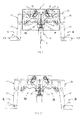
Fig.1 describes a partial view in perspective, of the two mechanisms for operating the breaking system, according to a particular embodiment of the invention, -
Fig.2 is a partial front and plan view of the switchgear according to a particular embodiment of the invention, in a closed position, -
Figures 3 to 5 are three views similar tofigure 2 , and illustrating several stages of the opening of the right hand switch of the switchgear according to the invention, -
Figure 6 describes a partial front and plan view similar tofigure 1 , at the end of opening of the switchgear, -
Figures 7 and 8 are partial views and in perspective, illustrating the internal part of the vacuum bottle respectively in a closed and in an open position of the contacts of the vacuum bottle, -
Figures 9 and10 are two views similar toFig.6 , and illustrating the switchgear at the end of the closing operation, -
Fig.11 is a front and plan view illustrating another embodiment of the switchgear according to the invention, in a closed position, -
Figure 12 to Figure 18 illustrate another embodiment of the switchgear, and in particular:-
Fig.12 is a front and plan view of this embodiment, -
Fig.13 is a partial view offig.12 illustrating a part of this switchgear comprising the two contact assemblies of the two switches, a connecting link and a vacuum bottle, -
Fig.14 is a partial and perspective view of one of the contacts assemblies which is not associated with the vacuum bottle, -
Fig.15 is a perspective view of the assembly offig.13 , -
Fig.16 is a top and elevation view of a vacuum bottle with a part of the mechanism for actuating its moveable contact, -
Fig.17 is a top view of the assembly offig.13 without the first contact assembly, and -
Fig.18 is a part of the second contact assembly associated with the vacuum bottle.
-
- The figures illustrate a part of a medium voltage switchgear according to the invention used in a ring main unit commonly called RMU and more particularly described in
EP 0 283189 - This ring main unit is composed principally of a first part comprising per phase two main switches disconnectors A,B connected on the one hand, to the distribution ring, and on the other hand, to a
common busbar 28, and a second part non illustrated in this figure, comprising one fuse-switch disconnector or circuit breaker per phase, and designed to protect a Medium voltage/Low Voltage transformer. All these switches of the two parts are grouped together into a unique tank filled with Nitrogen, CO2, Air or any fluorinated gas, as dielectric media, and sealed for life. The lower module has a first set of three bushes, non illustrated in this figure, one for each phase of a first three-phase electrical supply. Three conductors of the supply pass respectively through respective ones of the bushes to terminate within the lower chamber. Each of the conductors has an input contact which pivotally supports aswitching contact 23 respectively. Each of the switching contacts is connected by a respective link to an operating shaft non illustrated in this figure, all three switching contacts thus being driven from the same operating shaft. These switching contacts are be driven by rotation of shaft either downwardly into connection with respective earth contacts or upwardly into contact withrespective output contacts 27 electrically connected to respective bus bars. - A second set of three tapered input bushes and appropriate conductors, one for each phase of a second three-phase electrical supply, is associated with the lower module at the opposite side thereof, the arrangement being substantially a mirror image of the switching arrangement associated with input conductors. Thus, each conductor has an associated
switching contact 22 driven from an operating shaft so that it can adopt a central off position, a lower earth on position in contact with a respective one of three earth contacts, or an upper on position in contact with a respective one of threeoutput contacts 26. The lower chamber thus houses two single/three-phase ring switches A,B each capable of connecting a respective set of three input contacts to a respective set of three output contacts. Each switch is driven from a separate shaft, which is in turn driven by an operating mechanism under control of the respective switch control panel. - According to a particular and preferred embodiment of the invention, a
single vacuum interrupter 2 is used as breaking chamber for two medium voltage three position switches A,B, for each phase, in order to break a load current, these two switches belonging respectively to two independent circuits C1,C2. - The
common vacuum interrupter 2 act in parallel during breaking with either of the two switches which are located in front of each other. - In
figure 1 is disclosed the mechanism for operating themovable contact 42 of thevacuum interrupter 2. - This mechanism comprises four
pivot links 3, 18, 4, 19 mounted in articulated manner by one of their end with respect to a support, four connectinglinks movable contact 42 of thevacuum interrupter 2, foursliders bracket 13. The set of foursliders plate 8 allows the opening of vacuum bottle independently by theexternal sliders internal sliders bracket 13 atpoint Pivot links 3 and 18 are operated from right side and pivot links 4 and 19 are operated from left side. Two connecting links 5 and 16 are hinged withpivot links 3 and 18 respectively at one end by thecommon pin 35. The other end is hinged toslider links common pin 36 and withslider - These
pins respective slot bracket 13. - Said
sliders plate 8 which is holding bybush 7. Thebush 7 is connected to movingend 42 ofvacuum interrupter 2. Each pair ofpivot links 3, 18 and 4,19 are connected bycontact assembly contacts flexible wire end 42 of vacuum interrupter and the other end is connected to thecontact assembly - On this
figure 1 , it can be seen that under the pushingplate 8 an insulatingscreen 40 has been added which is moving when thevacuum bottle 2 is opening, which offer a dynamic insulation protection allowing to compact more the architecture by increasing the creepage distances between the two switches A,B. This insulatingscreen 40 is associated to astationary screen 41, the assembly of these two screens allowing to have a compact architecture, to reduce the chances of internal arc between functions, to achieve a quasi separation between functions which is important for the reliability of the device. - The sequencing principle will be described in the following with reference to
figures 1 to 10 . - During closing operation, the
vacuum interrupter 2 is not operating by the virtue ofpivot links 3,18 and 4,19. These links are toggling during closing operation and thus not affected to thevacuum interrupter 2. In close condition, the movingcontacts contact contacts common bus bar 28. - The right hand side switch will be noted RH switch whereas the left hand side switch will be noted LH switch.
- In
figure 2 , the switchgear according to the invention is in a closed position, in which the two switches are in a closed position. - At the beginning of the opening operation, the moving
contact 22 of the RH switch, pivoted atpoint 29, is activating by handle not shown in this figure. The movingcontact 22 starts rotating anti clock wise. Before it leaves the fixedcontact 26, it touches thecontact 20, as illustrated infigure 3 . Thus, one current is passing through fixedcontact 26 and movingcontact 22, and the other current is passing throughvacuum interrupter 2 and the movingcontact 22 via aflexible wire 24. During its movement, the movingcontact 22 operates the pivot levers 3,18 viacontact 20. Once the moving contact leaves the fixedcontact 26, as illustrated infigure 4 , whole current is passing through thevacuum interrupter 2. The rotational movement of the pivot levers 3, 18 operates the connecting links 5,16. These connecting links 5,16 moves thesliders figure 8 . Thus, these twosliders plate 8 . In the same time, thesliders plate 8 so that theLH contact 21 is not moving and thespring 32 is not involved in the operation, which is reducing the energy involved in the operation. As the pushingplate 8 is hold by thebush 7, it pulls downward the bush, which in turn pulls the moving stem or movingcontact 42 of the vacuum interrupter. As the moving stem operates, it separates from the fixedcontact 43 of the vacuum interrupter as illustrated infigure 5 and 6 . - Thus, the arcing is quenching rapidly due to high dielectric recovery of vacuum. As the moving contact of the vacuum interrupter is connected both to contact 20 and 21, it means that the gap between
fixed contact 26 and movingcontact 22, and betweenfixed contact 27 and movingcontact 23 must withstand the Transient Recovery Voltage (TRV), that could occurs depending on the incoming and outgoing network. To this end, aslot 39 is provided inpivot links 3,18 and 4,19 cooperating with pivot pins 35,36 belonging to connectinglinks pivot links 3, 18, and 4,19 which provides sufficient gap between movingcontact contact figure 4 . - After a certain degree of rotation of moving
contact 22, it leaves thecontact 20, which returns back pivot levers 3,18 to its original position due to spring 31 andstopper 33. Theseslots pins contact 22 leaves thecontact 20. Thevacuum interrupter 2 also returns to its close position and the pushingplate 8 too, so that the circuit is ready for an opening operation of the LH switch. As the operation takes less than 100ms, there is no chance that the operator will operate the second switch while the first is in process. The movingcontact 22 is stable at defined opening position. Thus, the opening operation is completed. - The closing operation is now disclosed as follows :
- The switch is operating to close by handle not shown in figure. The moving
contact 22 operates in clockwise direction. Almost at the end of travel, it touches to thecontact 20 at the back side which is insulated by plastic. Thus no current or arcing established. This time, thepivot lever 3,18 is not operated because the contact assembly is toggle due to some flexibility, as illustrated infig.9 andfig.10 . - Hence, the vacuum interrupter contacts remain stable and no current flows through vacuum interrupter. Finally, the moving
contact 22 is engaged with fixedcontact 26. Thus, the closing operation is completed, as disclosed infigure 10 . - During closing and opening operation of RH switch, pivot levers 4 and 19, connecting
links sliders - Similar operation happens when the LH switch is operated by operating handle.
- According to a preferred embodiment of the invention, the vacuum bottle is oriented vertically and directly connected to the
busbar 28. - As a result, it is possible to re-use the existing frame as disclosed in
EP 0 283 189 - The advantages relative to the use of a Circuit breaker system as disclosed in
EP 2 479769 - Due to the fact that the vacuum bottle is oriented vertically, it is possible to increase its rated voltage by increasing its length which advantageously does not impact the size of the switchgear with respect to width and depth.
- According to another embodiment illustrated in
figure 11 , the two switches E,F are linear switches and comprise movable contacts 47,48 which are moving in translation and no more in rotation and except this difference, the mechanisms for operating the vacuum bottle comprise the same elements as for the preceding embodiment and have the same reference numerals, as well as the sequencing principle is the same as previously disclosed. Consequently, the structure and the sequencing of this embodiment will not be disclosed again. - According to an alternative embodiment of the invention disclosed in
figures 12 to 18 , the invention is applied to a switch gear comprising two linearly arranged switches C,D comprising movable contacts 44,45 which are moving in rotation. In this embodiment, each switch is modular type, is independent, and has its own switching capacity. - With respect to the previous disclosed embodiment, the elements are the same and are referenced with the same reference numerals, the only difference being that one of the connecting link is replaced by a longer connecting
link 46 and the structure withsliders - This invention allows to offer a simple three positions switch that is using enduring and reliable vacuum technology to break the current.
- The use of only one vacuum bottle can save space, and reduce the cost of the switch compare to two switches as disclosed in
EP 2 479 769 - The invention allows to make it working independently from the two switches, and respecting the breaking sequence and optimizing the space needed.
- This invention can be used in both rotative and linear breaking technology and may be extended to circuit breaker.
- This invention will be used preferably as breaking technology in medium voltage switches rated from 1 kV to 52 kV.
- This type of switches will be advantageously used in secondary distribution system.
- It is provided due to the invention a reduction in size for two switches because only one breaking system is used instead of two, which is associated to a reduction in cost.
- A global electrical endurance is easy to improve compare to SF6 or gas or oil breaking system because vacuum technology is able to withstand more operations both electrically and mechanically.
- The configuration in which the switchgear uses rotation technology and a vacuum bottle oriented vertically, presents some advantages which are that the necessary space inside the switchgear is reduced, in that it is possible to increase the rated voltage as the vacuum bottle length is increasing, in that the distance between the movable contact of the vacuum bottle and the bus bar is increased resulting in no more necessity to provide over insulation such as sleeve around the vacuum bottle to withstand the TRV, and finally in that a single wire can be used for each switch which is places in line with the centre line or central axis X of vacuum interrupter, which allows to reduce the distance between phases, and consequently the isolating distance and consequently the congestion of the switchgear.
- Consequently of this, it is possible to use a bigger vacuum bottle, then to get an increased rated voltage while keeping a good insulation and without increasing the width of the apparatus which is the most important dimension of the switchgear. Another advantage of this particular configuration is that it is possible to place only one spring on the bus bar, what allows to fix its potential and to reduce the distance between devices. It is then possible to have a distance between phases of 105mm equivalent to the distance between the electric bushings whereas this was impossible in the current architectures which require at least a distance between phases of at least 125 mm. In fact, the distance between phase is depending only of the air gap needed for dielectric withstand plus the width of the levers plus the diameter of the vacuum bottle. For 12 kV design, it is then possible to keep the distance between phases of 105mm which is also the distance between the bushings allowing a direct connection between the bushings and the switch due to the new implementation of spring which allows to save distance between phases. These features allow a direct connection between the bushings and the switch.
- This configuration of the spring thus allows to reduce the in-depth dimensions of the switchgear. In the systems of the previous art, springs are placed in rotative center of
pivot links 31,32 offig.2 , what is cumbersome and furthermore, they are at floating potential, which increase the risks of partial discharges. - So, the novelty of this invention is the mutualisation of the breaking system between two independent medium voltage power electrical circuits and the making such a way that it behaves as per as if there was no mutualisation, said switchgear needing same energy to open the switch and the vacuum bottle, respecting the speed for vacuum bottle opening, respecting the sequence of closing, respecting the speed of closing.
- Then, such an architecture of switch gear panel allows to share the current breaking system between at least two switches allowing cost reduction on breaking system.
- Particularly, if the breaking system is the one described in
EP 2 479 769 - This architecture allows to keep almost same foot print that SF6 equipment and will work in equipment such as this disclosed in
EP 0 283 189 - The invention is naturally in no way limited to the embodiments that have been described and illustrated which have been given for example purposes only.
- On the contrary, the invention extends to encompass all technical equivalents of the means described as well as combinations thereof if the latter are performed according to the spirit of the invention.
Claims (20)
- Medium voltage switchgear comprising per phase, two switches, each switch comprising means for performing the disconnection function and means for performing the breaking function,
characterized in that it comprises per phase, one single breaking system (2), said breaking system being adapted to be operated, independently relative to each other, by either one or the other of two mechanisms M,N, said mechanisms being operated respectively by said two switches (A,B),(C,D),(E,F), said switches belonging respectively to two independent medium voltage power electrical circuits C1,C2. - Medium voltage switchgear according to claim 1, characterized in that said breaking system (2) uses vacuum break technology such as a vacuum bottle.
- Medium voltage switchgear according to claim 1 or 2, characterized in that one or each switch (A,B),(C,D) and (E,F) is a three-positions switch, respectively a current flow position, an open position, and an earthed position.
- Medium voltage switchgear according to claim 3, characterized in that one or each switch (A,B),(C,D) and (E,F) uses gas-insulated technology such nitrogen, C02, fluorinated gases, air,...and so on, and every mixture of such gases.
- Medium voltage switchgear according to any one of the preceding claims, characterized in that each switch is a one-phase switch or a three-phase switch.
- Medium voltage switchgear according to anyone of the preceding claims, characterized in that said breaking system (2) comprises a vacuum bottle, and in that each switch comprises a movable contact (22, 23) and a stationary contact (26,27), said stationary contacts (or said movable contacts) being electrically connected to a bus bar (28), and in that said vacuum bottle (2) is arranged so that its longitudinal direction extends sensibly perpendicularly to the longitudinal direction of said busbar (28).
- Medium voltage switchgear according to claim 6, characterized in that said stationary contact (43) of the vacuum bottle (2) is electrically connected to the busbar (28).
- Medium voltage switchgear according to claim 6 or 7, characterized in that said longitudinal direction of the vacuum bottle (2) is sensibly parallel to the height of the medium voltage switchgear.
- Medium voltage switchgear according to anyone of the claims 6 to 8, characterized in that each mechanism M,N comprises pivot links (3,18,4,19) pivoted on a bracket (13) of the switchgear, connecting links (5,16,6,17) being hinged by one of their ends, with pivot links (3,18,4,19) at one end of said pivot links, said pivot links comprising another end operating in conjunction with the movable contact (22,23) of the corresponding switch, and said connecting links operating in conjunction, by another of their ends, with the movable contact (42) of the vacuum bottle (2) by means of intermediary means allowing said two mechanisms to work independently one with respect to the other.
- Medium voltage switchgear according to claim 9, characterized in that said intermediary means comprise sliders (9,10,11,12) mounted sliding with respect to the vacuum bottle (2), said sliders comprising at least one internal sliders (11,12) drivable by one of said two mechanisms M,N, and at least one external sliders (9,10) drivable by the other of the two mechanisms, said sliders bearing on a plate (8) which itself bears on the movable contact (42) of the vacuum bottle (2).
- Medium voltage switchgear according to claim 9 or 10, characterized in that each mechanism M, N comprises a spring (31,32) provided for returning back said pivot links (3,18,4,19) to their original position after a certain degree of rotation of the moving contact (42) of the vacuum bottle (2), said spring comprising a first end bearing on said pivot levers and a second end bearing on the bus bar (28).
- Medium voltage switchgear according to anyone of claims 9 to 11, characterized in that it comprises, for each switch A,B, a slot (39) provided in pivot levers (3,18,4,19), said slot operating in conjunction with a pin (35,36) belonging to the corresponding connecting links (5,16,6,17), so that a sufficient gap between moving contact (22,23) and stationary contact (26,27) of the switch A,B is reached to withstand TRV before opening of vacuum breaking system (2).
- Medium voltage switchgear according to anyone of claims 9 to 12, characterized in that it comprises for each mechanism M,N, a slot (37,38) provided in the bracket (13) of the switchgear and able to operate in conjunction with said pin (35,36) integrated with said corresponding connecting links (5,16,6,17), so that this slot guide the movement of the pin and connecting links such that the vacuum bottle will open with the speed that allows to break the current, and up to its full stroke and remain open for 20 to 30ms.
- Medium voltage switchgear according to anyone of the preceding claims, characterized in that it comprises per phase, two front switches A,B being arranged one with respect to the other, so that their moving contacts (22,23) moves in rotation in opposite direction.
- Medium voltage switchgear according to claim 14, characterized in that each mechanism M,N comprises a flexible wire (24,25), said wire being connected by one of its ends, to the moving contact (42) of said vacuum bottle (2), and by its other end, to the corresponding contact assembly (20,21), said wire extending in a plane sensibly parallel to the plane comprising the two switches and the central axis X of said vacuum bottle (2).
- Medium voltage switchgear according to claim 14 or 15, characterized in that it comprises at least one isolating shield (40) integral with the moving contact (42) of the vacuum bottle (2) and a stationary shield (41) adapted to work as a dielectric barrier.
- Medium voltage switchgear according to anyone of claims 9 to 13, characterized in that it comprises per phase, two linearly arranged switches C,D having their moving contacts (44,45) moving in rotation in same direction, one of said connecting links being replaced by a longer connecting link (46) and said sliders (9,10,11,12) being added around the vacuum bottle (2).
- Medium voltage switchgear according to any one of claims 9 to 13, characterized in that it comprises per phase, two linear switches (E,F) having their moving contacts (47,48) moving in translation in same direction.
- Medium voltage switchgear according to anyone of the preceding claims, characterized in that it is rated from 1 KV to 52 KV.
- Medium voltage switchgear according to any one of the preceding claims, characterized in that it is a circuit breaker, an interrupter or a load break switch.
Applications Claiming Priority (1)
| Application Number | Priority Date | Filing Date | Title |
|---|---|---|---|
| IN434KO2014 IN2014KO00434A (en) | 2014-04-03 | 2014-04-03 |
Publications (2)
| Publication Number | Publication Date |
|---|---|
| EP2927926A1 true EP2927926A1 (en) | 2015-10-07 |
| EP2927926B1 EP2927926B1 (en) | 2017-02-01 |
Family
ID=54275549
Family Applications (1)
| Application Number | Title | Priority Date | Filing Date |
|---|---|---|---|
| EP15305395.4A Active EP2927926B1 (en) | 2014-04-03 | 2015-03-18 | Medium voltage switchgear comprising two switches per phase |
Country Status (3)
| Country | Link |
|---|---|
| EP (1) | EP2927926B1 (en) |
| CN (1) | CN104979129B (en) |
| IN (1) | IN2014KO00434A (en) |
Cited By (3)
| Publication number | Priority date | Publication date | Assignee | Title |
|---|---|---|---|---|
| CN115000864A (en) * | 2022-07-20 | 2022-09-02 | 华源中瑞科技(北京)有限公司 | A ring network switch cabinet |
| WO2023285716A1 (en) * | 2021-07-13 | 2023-01-19 | Ormazabal Corporate Technology, A.I.E. | Load break or short-circuit currents switch and electrical equipment incorporating said switch |
| EP4195229A1 (en) * | 2021-12-13 | 2023-06-14 | Schneider Electric Industries SAS | Apparatus for interrupting current on an electrical line comprising a vacuum bulb |
Families Citing this family (3)
| Publication number | Priority date | Publication date | Assignee | Title |
|---|---|---|---|---|
| CN110660607B (en) * | 2019-09-30 | 2021-06-25 | 顾天琪 | Bridge type contact load switch and smart electric meter |
| CN111968877A (en) * | 2020-09-17 | 2020-11-20 | 安徽普众机电有限公司 | High-voltage vacuum circuit breaker structure |
| CN114446679A (en) * | 2022-01-26 | 2022-05-06 | 沈阳斯沃电器有限公司 | Isolating switch |
Citations (6)
| Publication number | Priority date | Publication date | Assignee | Title |
|---|---|---|---|---|
| US3070680A (en) * | 1959-02-27 | 1962-12-25 | Chance Co Ab | Switch gear |
| US4220837A (en) * | 1977-01-06 | 1980-09-02 | Westinghouse Electric Corp. | Bi-switch construction having an auxiliary interrupting device associated therewith |
| EP0283189A2 (en) | 1987-03-12 | 1988-09-21 | Merlin Gerin Limited | Electrical ring main unit |
| DE4008623A1 (en) * | 1990-03-17 | 1991-09-19 | Driescher Spezialfab Fritz | Metal encapsulated electric switchgear - has circuit breaker with switching drive mechanically linked to load-separating switch |
| EP2479769A1 (en) | 2011-01-25 | 2012-07-25 | Schneider Electric Industries SAS | Medium-voltage cutting device including a vacuum tube |
| EP2565897A1 (en) * | 2011-08-29 | 2013-03-06 | Hitachi Ltd. | Switchgear and switchgear operating method |
Family Cites Families (1)
| Publication number | Priority date | Publication date | Assignee | Title |
|---|---|---|---|---|
| US8319136B2 (en) * | 2010-06-29 | 2012-11-27 | Schneider Electric USA, Inc. | Arcing fault and arc flash protection system having a high-speed switch |
-
2014
- 2014-04-03 IN IN434KO2014 patent/IN2014KO00434A/en unknown
-
2015
- 2015-03-18 EP EP15305395.4A patent/EP2927926B1/en active Active
- 2015-04-02 CN CN201510153536.1A patent/CN104979129B/en active Active
Patent Citations (6)
| Publication number | Priority date | Publication date | Assignee | Title |
|---|---|---|---|---|
| US3070680A (en) * | 1959-02-27 | 1962-12-25 | Chance Co Ab | Switch gear |
| US4220837A (en) * | 1977-01-06 | 1980-09-02 | Westinghouse Electric Corp. | Bi-switch construction having an auxiliary interrupting device associated therewith |
| EP0283189A2 (en) | 1987-03-12 | 1988-09-21 | Merlin Gerin Limited | Electrical ring main unit |
| DE4008623A1 (en) * | 1990-03-17 | 1991-09-19 | Driescher Spezialfab Fritz | Metal encapsulated electric switchgear - has circuit breaker with switching drive mechanically linked to load-separating switch |
| EP2479769A1 (en) | 2011-01-25 | 2012-07-25 | Schneider Electric Industries SAS | Medium-voltage cutting device including a vacuum tube |
| EP2565897A1 (en) * | 2011-08-29 | 2013-03-06 | Hitachi Ltd. | Switchgear and switchgear operating method |
Cited By (5)
| Publication number | Priority date | Publication date | Assignee | Title |
|---|---|---|---|---|
| WO2023285716A1 (en) * | 2021-07-13 | 2023-01-19 | Ormazabal Corporate Technology, A.I.E. | Load break or short-circuit currents switch and electrical equipment incorporating said switch |
| EP4195229A1 (en) * | 2021-12-13 | 2023-06-14 | Schneider Electric Industries SAS | Apparatus for interrupting current on an electrical line comprising a vacuum bulb |
| FR3130446A1 (en) * | 2021-12-13 | 2023-06-16 | Schneider Electric Industries Sas | Switching device on an electric line comprising a vacuum interrupter |
| US12087527B2 (en) | 2021-12-13 | 2024-09-10 | Schneider Electric Industries Sas | Switching device on an electric line comprising a vacuum interrupter |
| CN115000864A (en) * | 2022-07-20 | 2022-09-02 | 华源中瑞科技(北京)有限公司 | A ring network switch cabinet |
Also Published As
| Publication number | Publication date |
|---|---|
| IN2014KO00434A (en) | 2015-10-09 |
| CN104979129A (en) | 2015-10-14 |
| EP2927926B1 (en) | 2017-02-01 |
| CN104979129B (en) | 2019-10-08 |
Similar Documents
| Publication | Publication Date | Title |
|---|---|---|
| EP2927926B1 (en) | Medium voltage switchgear comprising two switches per phase | |
| CN104576175B (en) | High-voltage double-break circuit breaker | |
| CN104335312B (en) | Three-position load isolating switch for medium-voltage switchgear assemblies | |
| US8081407B2 (en) | Compact disconnector circuit-breaker for an alternator | |
| JP4906892B2 (en) | Switchgear | |
| AU2009334695B2 (en) | Medium-voltage electric distribution cubicle | |
| US8975550B2 (en) | Switch unit and switchgear | |
| EP2565897A1 (en) | Switchgear and switchgear operating method | |
| CN115602480A (en) | Three-position switch and three-position environment-friendly gas combined electric appliance ring main unit | |
| EP3046128B1 (en) | Shunt breaking system | |
| CN102176396B (en) | Three-phase common-box type high-speed earthing switch device | |
| KR20070092590A (en) | Medium Voltage Switchgear | |
| JP5183794B2 (en) | Switchgear | |
| KR100370103B1 (en) | Disconnecting switch of Gas Insulator Switchgear | |
| EP3046129B1 (en) | Shunt breaking system | |
| KR101279894B1 (en) | Switch for solid insulated switchgear | |
| EP3716422A1 (en) | Gas-insulated switchgear for electric distribution networks | |
| JP7766127B2 (en) | Switchgear structure | |
| KR20150134206A (en) | Gas circuit breaker for gas insulated switchgear | |
| CN105990068B (en) | shunt break system | |
| KR100281086B1 (en) | Gas Insulated Switchgear | |
| WO2026062418A1 (en) | Load break switch assembly with shunt vacuum interruption | |
| RU2609567C1 (en) | High-voltage circuit breaker | |
| CN114342029A (en) | Single-pole disconnector with vacuum interrupter as auxiliary contact system | |
| JP2633643B2 (en) | Three-phase batch gas circuit breaker |
Legal Events
| Date | Code | Title | Description |
|---|---|---|---|
| PUAI | Public reference made under article 153(3) epc to a published international application that has entered the european phase |
Free format text: ORIGINAL CODE: 0009012 |
|
| AK | Designated contracting states |
Kind code of ref document: A1 Designated state(s): AL AT BE BG CH CY CZ DE DK EE ES FI FR GB GR HR HU IE IS IT LI LT LU LV MC MK MT NL NO PL PT RO RS SE SI SK SM TR |
|
| AX | Request for extension of the european patent |
Extension state: BA ME |
|
| 17P | Request for examination filed |
Effective date: 20151103 |
|
| RBV | Designated contracting states (corrected) |
Designated state(s): AL AT BE BG CH CY CZ DE DK EE ES FI FR GB GR HR HU IE IS IT LI LT LU LV MC MK MT NL NO PL PT RO RS SE SI SK SM TR |
|
| GRAP | Despatch of communication of intention to grant a patent |
Free format text: ORIGINAL CODE: EPIDOSNIGR1 |
|
| RIC1 | Information provided on ipc code assigned before grant |
Ipc: H01H 33/12 20060101AFI20160831BHEP Ipc: H01H 33/666 20060101ALI20160831BHEP |
|
| INTG | Intention to grant announced |
Effective date: 20160929 |
|
| GRAS | Grant fee paid |
Free format text: ORIGINAL CODE: EPIDOSNIGR3 |
|
| GRAA | (expected) grant |
Free format text: ORIGINAL CODE: 0009210 |
|
| AK | Designated contracting states |
Kind code of ref document: B1 Designated state(s): AL AT BE BG CH CY CZ DE DK EE ES FI FR GB GR HR HU IE IS IT LI LT LU LV MC MK MT NL NO PL PT RO RS SE SI SK SM TR |
|
| REG | Reference to a national code |
Ref country code: GB Ref legal event code: FG4D |
|
| REG | Reference to a national code |
Ref country code: CH Ref legal event code: EP Ref country code: AT Ref legal event code: REF Ref document number: 866171 Country of ref document: AT Kind code of ref document: T Effective date: 20170215 |
|
| REG | Reference to a national code |
Ref country code: IE Ref legal event code: FG4D |
|
| REG | Reference to a national code |
Ref country code: FR Ref legal event code: PLFP Year of fee payment: 3 |
|
| REG | Reference to a national code |
Ref country code: DE Ref legal event code: R096 Ref document number: 602015001438 Country of ref document: DE |
|
| REG | Reference to a national code |
Ref country code: NL Ref legal event code: MP Effective date: 20170201 |
|
| REG | Reference to a national code |
Ref country code: LT Ref legal event code: MG4D |
|
| REG | Reference to a national code |
Ref country code: AT Ref legal event code: MK05 Ref document number: 866171 Country of ref document: AT Kind code of ref document: T Effective date: 20170201 |
|
| PG25 | Lapsed in a contracting state [announced via postgrant information from national office to epo] |
Ref country code: LT Free format text: LAPSE BECAUSE OF FAILURE TO SUBMIT A TRANSLATION OF THE DESCRIPTION OR TO PAY THE FEE WITHIN THE PRESCRIBED TIME-LIMIT Effective date: 20170201 Ref country code: FI Free format text: LAPSE BECAUSE OF FAILURE TO SUBMIT A TRANSLATION OF THE DESCRIPTION OR TO PAY THE FEE WITHIN THE PRESCRIBED TIME-LIMIT Effective date: 20170201 Ref country code: NO Free format text: LAPSE BECAUSE OF FAILURE TO SUBMIT A TRANSLATION OF THE DESCRIPTION OR TO PAY THE FEE WITHIN THE PRESCRIBED TIME-LIMIT Effective date: 20170501 Ref country code: IS Free format text: LAPSE BECAUSE OF FAILURE TO SUBMIT A TRANSLATION OF THE DESCRIPTION OR TO PAY THE FEE WITHIN THE PRESCRIBED TIME-LIMIT Effective date: 20170601 Ref country code: HR Free format text: LAPSE BECAUSE OF FAILURE TO SUBMIT A TRANSLATION OF THE DESCRIPTION OR TO PAY THE FEE WITHIN THE PRESCRIBED TIME-LIMIT Effective date: 20170201 Ref country code: GR Free format text: LAPSE BECAUSE OF FAILURE TO SUBMIT A TRANSLATION OF THE DESCRIPTION OR TO PAY THE FEE WITHIN THE PRESCRIBED TIME-LIMIT Effective date: 20170502 |
|
| PG25 | Lapsed in a contracting state [announced via postgrant information from national office to epo] |
Ref country code: SE Free format text: LAPSE BECAUSE OF FAILURE TO SUBMIT A TRANSLATION OF THE DESCRIPTION OR TO PAY THE FEE WITHIN THE PRESCRIBED TIME-LIMIT Effective date: 20170201 Ref country code: PT Free format text: LAPSE BECAUSE OF FAILURE TO SUBMIT A TRANSLATION OF THE DESCRIPTION OR TO PAY THE FEE WITHIN THE PRESCRIBED TIME-LIMIT Effective date: 20170601 Ref country code: NL Free format text: LAPSE BECAUSE OF NON-PAYMENT OF DUE FEES Effective date: 20170201 Ref country code: RS Free format text: LAPSE BECAUSE OF FAILURE TO SUBMIT A TRANSLATION OF THE DESCRIPTION OR TO PAY THE FEE WITHIN THE PRESCRIBED TIME-LIMIT Effective date: 20170201 Ref country code: BG Free format text: LAPSE BECAUSE OF FAILURE TO SUBMIT A TRANSLATION OF THE DESCRIPTION OR TO PAY THE FEE WITHIN THE PRESCRIBED TIME-LIMIT Effective date: 20170501 Ref country code: PL Free format text: LAPSE BECAUSE OF FAILURE TO SUBMIT A TRANSLATION OF THE DESCRIPTION OR TO PAY THE FEE WITHIN THE PRESCRIBED TIME-LIMIT Effective date: 20170201 Ref country code: ES Free format text: LAPSE BECAUSE OF FAILURE TO SUBMIT A TRANSLATION OF THE DESCRIPTION OR TO PAY THE FEE WITHIN THE PRESCRIBED TIME-LIMIT Effective date: 20170201 Ref country code: AT Free format text: LAPSE BECAUSE OF FAILURE TO SUBMIT A TRANSLATION OF THE DESCRIPTION OR TO PAY THE FEE WITHIN THE PRESCRIBED TIME-LIMIT Effective date: 20170201 Ref country code: LV Free format text: LAPSE BECAUSE OF FAILURE TO SUBMIT A TRANSLATION OF THE DESCRIPTION OR TO PAY THE FEE WITHIN THE PRESCRIBED TIME-LIMIT Effective date: 20170201 |
|
| PG25 | Lapsed in a contracting state [announced via postgrant information from national office to epo] |
Ref country code: EE Free format text: LAPSE BECAUSE OF FAILURE TO SUBMIT A TRANSLATION OF THE DESCRIPTION OR TO PAY THE FEE WITHIN THE PRESCRIBED TIME-LIMIT Effective date: 20170201 Ref country code: CZ Free format text: LAPSE BECAUSE OF FAILURE TO SUBMIT A TRANSLATION OF THE DESCRIPTION OR TO PAY THE FEE WITHIN THE PRESCRIBED TIME-LIMIT Effective date: 20170201 Ref country code: IT Free format text: LAPSE BECAUSE OF FAILURE TO SUBMIT A TRANSLATION OF THE DESCRIPTION OR TO PAY THE FEE WITHIN THE PRESCRIBED TIME-LIMIT Effective date: 20170201 Ref country code: RO Free format text: LAPSE BECAUSE OF FAILURE TO SUBMIT A TRANSLATION OF THE DESCRIPTION OR TO PAY THE FEE WITHIN THE PRESCRIBED TIME-LIMIT Effective date: 20170201 Ref country code: SK Free format text: LAPSE BECAUSE OF FAILURE TO SUBMIT A TRANSLATION OF THE DESCRIPTION OR TO PAY THE FEE WITHIN THE PRESCRIBED TIME-LIMIT Effective date: 20170201 |
|
| REG | Reference to a national code |
Ref country code: DE Ref legal event code: R097 Ref document number: 602015001438 Country of ref document: DE |
|
| PG25 | Lapsed in a contracting state [announced via postgrant information from national office to epo] |
Ref country code: MC Free format text: LAPSE BECAUSE OF FAILURE TO SUBMIT A TRANSLATION OF THE DESCRIPTION OR TO PAY THE FEE WITHIN THE PRESCRIBED TIME-LIMIT Effective date: 20170201 Ref country code: DK Free format text: LAPSE BECAUSE OF FAILURE TO SUBMIT A TRANSLATION OF THE DESCRIPTION OR TO PAY THE FEE WITHIN THE PRESCRIBED TIME-LIMIT Effective date: 20170201 Ref country code: SM Free format text: LAPSE BECAUSE OF FAILURE TO SUBMIT A TRANSLATION OF THE DESCRIPTION OR TO PAY THE FEE WITHIN THE PRESCRIBED TIME-LIMIT Effective date: 20170201 |
|
| PLBE | No opposition filed within time limit |
Free format text: ORIGINAL CODE: 0009261 |
|
| STAA | Information on the status of an ep patent application or granted ep patent |
Free format text: STATUS: NO OPPOSITION FILED WITHIN TIME LIMIT |
|
| REG | Reference to a national code |
Ref country code: IE Ref legal event code: MM4A |
|
| 26N | No opposition filed |
Effective date: 20171103 |
|
| PG25 | Lapsed in a contracting state [announced via postgrant information from national office to epo] |
Ref country code: LU Free format text: LAPSE BECAUSE OF NON-PAYMENT OF DUE FEES Effective date: 20170318 |
|
| PG25 | Lapsed in a contracting state [announced via postgrant information from national office to epo] |
Ref country code: SI Free format text: LAPSE BECAUSE OF FAILURE TO SUBMIT A TRANSLATION OF THE DESCRIPTION OR TO PAY THE FEE WITHIN THE PRESCRIBED TIME-LIMIT Effective date: 20170201 Ref country code: IE Free format text: LAPSE BECAUSE OF NON-PAYMENT OF DUE FEES Effective date: 20170318 |
|
| REG | Reference to a national code |
Ref country code: BE Ref legal event code: MM Effective date: 20170331 |
|
| REG | Reference to a national code |
Ref country code: FR Ref legal event code: PLFP Year of fee payment: 4 |
|
| PG25 | Lapsed in a contracting state [announced via postgrant information from national office to epo] |
Ref country code: BE Free format text: LAPSE BECAUSE OF NON-PAYMENT OF DUE FEES Effective date: 20170331 |
|
| PG25 | Lapsed in a contracting state [announced via postgrant information from national office to epo] |
Ref country code: MT Free format text: LAPSE BECAUSE OF NON-PAYMENT OF DUE FEES Effective date: 20170318 |
|
| REG | Reference to a national code |
Ref country code: CH Ref legal event code: PL |
|
| PG25 | Lapsed in a contracting state [announced via postgrant information from national office to epo] |
Ref country code: CH Free format text: LAPSE BECAUSE OF NON-PAYMENT OF DUE FEES Effective date: 20180331 Ref country code: LI Free format text: LAPSE BECAUSE OF NON-PAYMENT OF DUE FEES Effective date: 20180331 |
|
| PG25 | Lapsed in a contracting state [announced via postgrant information from national office to epo] |
Ref country code: HU Free format text: LAPSE BECAUSE OF FAILURE TO SUBMIT A TRANSLATION OF THE DESCRIPTION OR TO PAY THE FEE WITHIN THE PRESCRIBED TIME-LIMIT; INVALID AB INITIO Effective date: 20150318 |
|
| PG25 | Lapsed in a contracting state [announced via postgrant information from national office to epo] |
Ref country code: CY Free format text: LAPSE BECAUSE OF FAILURE TO SUBMIT A TRANSLATION OF THE DESCRIPTION OR TO PAY THE FEE WITHIN THE PRESCRIBED TIME-LIMIT Effective date: 20170201 |
|
| PG25 | Lapsed in a contracting state [announced via postgrant information from national office to epo] |
Ref country code: MK Free format text: LAPSE BECAUSE OF FAILURE TO SUBMIT A TRANSLATION OF THE DESCRIPTION OR TO PAY THE FEE WITHIN THE PRESCRIBED TIME-LIMIT Effective date: 20170201 |
|
| PG25 | Lapsed in a contracting state [announced via postgrant information from national office to epo] |
Ref country code: TR Free format text: LAPSE BECAUSE OF FAILURE TO SUBMIT A TRANSLATION OF THE DESCRIPTION OR TO PAY THE FEE WITHIN THE PRESCRIBED TIME-LIMIT Effective date: 20170201 |
|
| PG25 | Lapsed in a contracting state [announced via postgrant information from national office to epo] |
Ref country code: AL Free format text: LAPSE BECAUSE OF FAILURE TO SUBMIT A TRANSLATION OF THE DESCRIPTION OR TO PAY THE FEE WITHIN THE PRESCRIBED TIME-LIMIT Effective date: 20170201 |
|
| PGFP | Annual fee paid to national office [announced via postgrant information from national office to epo] |
Ref country code: GB Payment date: 20260324 Year of fee payment: 12 |
|
| PGFP | Annual fee paid to national office [announced via postgrant information from national office to epo] |
Ref country code: DE Payment date: 20260326 Year of fee payment: 12 |
|
| PGFP | Annual fee paid to national office [announced via postgrant information from national office to epo] |
Ref country code: FR Payment date: 20260323 Year of fee payment: 12 |