EP2927784A1 - Improvement of the ergonomics of a data input device - Google Patents
Improvement of the ergonomics of a data input device Download PDFInfo
- Publication number
- EP2927784A1 EP2927784A1 EP15248039.8A EP15248039A EP2927784A1 EP 2927784 A1 EP2927784 A1 EP 2927784A1 EP 15248039 A EP15248039 A EP 15248039A EP 2927784 A1 EP2927784 A1 EP 2927784A1
- Authority
- EP
- European Patent Office
- Prior art keywords
- zone
- axis
- operator
- button
- ring
- Prior art date
- Legal status (The legal status is an assumption and is not a legal conclusion. Google has not performed a legal analysis and makes no representation as to the accuracy of the status listed.)
- Granted
Links
- 230000000284 resting effect Effects 0.000 claims abstract description 4
- 238000006073 displacement reaction Methods 0.000 claims description 4
- 210000003811 finger Anatomy 0.000 description 18
- 210000003813 thumb Anatomy 0.000 description 7
- 238000010200 validation analysis Methods 0.000 description 7
- 235000021183 entrée Nutrition 0.000 description 3
- 238000013479 data entry Methods 0.000 description 2
- 210000005224 forefinger Anatomy 0.000 description 2
- 210000000707 wrist Anatomy 0.000 description 1
Images


Classifications
-
- G—PHYSICS
- G06—COMPUTING; CALCULATING OR COUNTING
- G06F—ELECTRIC DIGITAL DATA PROCESSING
- G06F3/00—Input arrangements for transferring data to be processed into a form capable of being handled by the computer; Output arrangements for transferring data from processing unit to output unit, e.g. interface arrangements
- G06F3/01—Input arrangements or combined input and output arrangements for interaction between user and computer
- G06F3/03—Arrangements for converting the position or the displacement of a member into a coded form
- G06F3/033—Pointing devices displaced or positioned by the user, e.g. mice, trackballs, pens or joysticks; Accessories therefor
- G06F3/0362—Pointing devices displaced or positioned by the user, e.g. mice, trackballs, pens or joysticks; Accessories therefor with detection of 1D translations or rotations of an operating part of the device, e.g. scroll wheels, sliders, knobs, rollers or belts
-
- B—PERFORMING OPERATIONS; TRANSPORTING
- B60—VEHICLES IN GENERAL
- B60K—ARRANGEMENT OR MOUNTING OF PROPULSION UNITS OR OF TRANSMISSIONS IN VEHICLES; ARRANGEMENT OR MOUNTING OF PLURAL DIVERSE PRIME-MOVERS IN VEHICLES; AUXILIARY DRIVES FOR VEHICLES; INSTRUMENTATION OR DASHBOARDS FOR VEHICLES; ARRANGEMENTS IN CONNECTION WITH COOLING, AIR INTAKE, GAS EXHAUST OR FUEL SUPPLY OF PROPULSION UNITS IN VEHICLES
- B60K35/00—Arrangement of adaptations of instruments
-
- B60K35/10—
-
- G—PHYSICS
- G06—COMPUTING; CALCULATING OR COUNTING
- G06F—ELECTRIC DIGITAL DATA PROCESSING
- G06F3/00—Input arrangements for transferring data to be processed into a form capable of being handled by the computer; Output arrangements for transferring data from processing unit to output unit, e.g. interface arrangements
- G06F3/01—Input arrangements or combined input and output arrangements for interaction between user and computer
- G06F3/03—Arrangements for converting the position or the displacement of a member into a coded form
- G06F3/033—Pointing devices displaced or positioned by the user, e.g. mice, trackballs, pens or joysticks; Accessories therefor
- G06F3/0354—Pointing devices displaced or positioned by the user, e.g. mice, trackballs, pens or joysticks; Accessories therefor with detection of 2D relative movements between the device, or an operating part thereof, and a plane or surface, e.g. 2D mice, trackballs, pens or pucks
- G06F3/03549—Trackballs
-
- H—ELECTRICITY
- H01—ELECTRIC ELEMENTS
- H01H—ELECTRIC SWITCHES; RELAYS; SELECTORS; EMERGENCY PROTECTIVE DEVICES
- H01H25/00—Switches with compound movement of handle or other operating part
- H01H25/06—Operating part movable both angularly and rectilinearly, the rectilinear movement being along the axis of angular movement
- H01H25/065—Operating part movable both angularly and rectilinearly, the rectilinear movement being along the axis of angular movement using separate operating parts, e.g. a push button surrounded by a rotating knob
-
- B60K2360/11—
-
- B60K2360/115—
-
- B60K2360/135—
-
- H—ELECTRICITY
- H01—ELECTRIC ELEMENTS
- H01H—ELECTRIC SWITCHES; RELAYS; SELECTORS; EMERGENCY PROTECTIVE DEVICES
- H01H2217/00—Facilitation of operation; Human engineering
- H01H2217/034—Support for hands or arms
Definitions
- the invention relates to a data input device comprising a designator capable of pointing a position on a screen of a computer system to which the device is connected.
- the most used designator is a mouse whose position on a flat surface allows an operator to point a position on a computer system screen.
- Many other designators are also implemented such as for example a touchpad (or touchpad in English literature) fixed near a system keyboard, a mini-stick (or joystick), a designation ball (or track ball).
- Designators can be grouped into two large families, those having a fixed part such as the touch surface, the mini-stick and the designation ball and those having no fixed part like the mouse.
- a designator allows to point different positions on the screen. To move between two positions, the operator moves a moving part of the designator or his finger in the case of the touchpad. The displacement is measured in an orthogonal coordinate system that the computer system maps to a mark on the screen.
- the support surface is directly formed by the shape of the mouse on which the operator places the palm of the hand.
- the support surface has a shape, for example in portion of sphere, which allows to marry the inner surface of the palm of the hand.
- the designator can be associated with several buttons for entering data such as a push button allowing for example the validation of a value pointed by the designator.
- a push button allowing for example the validation of a value pointed by the designator.
- this type of push button is usually located on one side of the palm rest. The operation of this button is done with the thumb of the operator.
- rotary knobs In the vicinity of the designator, it is possible to find rotary knobs with a double ring, in particular allowing a coarse adjustment of the value of a data item for one of the rings and a fine adjustment of the same value for the other ring.
- the distance separating the rotary knob from the validation button requires the operator to move his hand between a position for selecting the value on the rotary knob and a validation position on the side of the palm rest. More precisely, the rotary knob is generally operated between the thumb and the index finger. The thumb must be moved to reach the validation button.
- the invention aims to improve the ergonomics of a data input device having multiple actuators.
- the subject of the invention is a data input device comprising a designator capable of pointing a position on a screen of a computer system to which the device is intended to be connected and a body intended to be fixed on a workstation, the body comprising a bearing zone intended to support the hand of an operator when maneuvering the designator, characterized in that it further comprises a button arranged to be operated by the operator's finger, his hand remaining in support on the support zone, and in that the button is configured to allow at least three distinct data selections including two choices of values, each in a series and a binary input in relation to one of the chosen values.
- the button comprises a ring rotating about an axis and allowing the choice of values in a series, the ring having a first zone and a second zone integral with each other and both having a shape substantially frustoconical extending around the axis on which the operator can lay the fingers.
- a smaller diameter of the first zone about the axis is greater than or equal to a larger diameter of the second zone about the axis.
- An angle at the apex ⁇ 2 of the first zone and an apex angle ⁇ 1 of the second zone are defined. The angles at the top verify the relationship: 0 ⁇ ° ⁇ ⁇ 1 ⁇ ⁇ 2 ⁇ 90 ⁇ ° .
- the figure 1 represents a data input device 10 comprising a designator such as a designation ball formed of a sphere 11 rotatable on itself with respect to a fixed body.
- the designation ball comprises a set of sensors delivering relative position information of the sphere 11 relative to the body.
- the information can be coded by a calculator.
- the sensor assembly and possibly the computer are arranged inside the fixed body.
- the coded information is for example intended to be used to designate an object on the screen of a computer system.
- the fixed body comprises a square or rectangular plate 12 intended to be fixed on the dashboard of an aircraft. It is understood that the invention is not limited to use in a cockpit of an aircraft. It can be implemented in any other field where the body of the data input device is attached to a workstation.
- the fixed body may also include a housing located under the plate 12, not shown on the figure 1 and containing the calculator and the set of sensors.
- the figure 2 represents the data input device 10 manipulated by the hand 13 of an operator.
- the data entry device 10 comprises a palm rest 15 on which an operator can press the palm of his hand when he uses the device 10.
- the palm rest 15 is integral with the fixed body.
- the palm rest 15 is prominent with respect to the plate 12.
- the palm rest extends mainly in an arc 16 closing towards an area intended to receive the fingers of the hand 13 of the operator operating the designator, in this case the sphere 11.
- the palm rest 15 is ambidextrous. It can be used by the right or left hand of an operator.
- two bearing zones 17 and 18 are provided on the surface of the palm rest 15.
- the bearing zone 17 is essentially designed to receive a left hand and the support zone 18 for receiving a right hand.
- the invention can of course be implemented for a data input device having only one support zone.
- the device comprises at least one button 20 arranged so as to be operated by the fingers of the operator, his hand remaining resting on the support zone.
- the arc 16 has two ends, and the button 20 is disposed at one end of the arc 16.
- the device comprises two identical buttons 20 and 21, the button 20 being associated to the support zone 17 and the button 21 to the support zone 18.
- the two buttons 20 and 21 are each disposed at one end of the arc 16.
- the hand 13 of the operator can manipulate the designator and the button associated with the support zone considered.
- the button is manipulated between the thumb and forefinger of the hand 13. During this manipulation the operator can still rotate the sphere 11.
- the figure 3 represents a portion of the palm rest associated with the button 21 and the Figures 4a and 4b
- the button 21 is configured to allow at least two distinct data selections including a choice of values in a series and a binary input in relation to the chosen value.
- the choice of value can be proportional or realized in a discrete series of values.
- the button 21 is configured to allow two choices of values, each in a series, the binary input 25 in relation to one of the values chosen.
- the button 21 comprises two concentric rings 23 and 24 on which the operator can put the fingers.
- the rings are each configured for selection from a choice of value and a push switch 25 configured for binary input.
- the rings 23 and 24 can both rotate independently of one another about the same axis 26.
- the rings 23 and 24 are preferably knurled or notched to allow better handling between the fingers of the operator.
- Each of the rings 23 and 24 drives a rotary switch for selection.
- the switch may comprise several discrete positions distributed around the axis 26.
- the ring in question may cause the cursor of a potentiometer to select a value linearly in a continuous domain.
- the ring 23 may have the shape of a substantially flat washer whose plane is perpendicular to the axis 26. Other shapes are of course possible, such as for example a truncated cone with axis 26 and corner at the top ⁇ 2 or even a cylinder portion. In the case of a flat washer, it is considered that the apex angle ⁇ 2 is equal to 90 °.
- the ring 24 has a cylindrical or slightly conical shape with an apex angle ⁇ 1 whose largest diameter is less than or equal to the smallest diameter of the ring 23. In these of a cylindrical shape, it is considered that the apex angle ⁇ 2 is equal to 0 °.
- the angle ⁇ 2 is advantageously greater than the angle ⁇ 1 to facilitate the operation of the button by an operator.
- the smallest diameter d of the ring 23 coincides with the largest diameter of the ring 24.
- the corners at the vertex satisfy the relation: 0 ⁇ ° ⁇ ⁇ 1 ⁇ ⁇ 2 ⁇ 90 ⁇ ° .
- the switch 25 is arranged in the center of the ring 24. It is configured to be operated in translation along the axis 26.
- the switch 25 has a circular bearing surface disposed in the center of the ring 24.
- the button 21 can be associated with the choice and the validation of a single value. More precisely, the ring 23 can allow a coarse adjustment or fast scrolling of possible values. The ring 24 may allow a fine adjustment or a slow scroll around the chosen value with the ring 23. Finally, the switch can allow validation of the value once both settings, coarse and fine executed.
- the Figures 5a, 5b and 5c represent the button 21 manipulated by the hand 13 of the operator.
- the hand 13 manipulates the ring 23 of the end of the index finger.
- the hand 13 manipulates the ring 24 between the thumb and forefinger.
- the hand 13 manipulates the switch 25 with the index finger.
- the rings 23, 24 and the switch 25 the same finger, the index in this case, can perform successively the three manipulations without detaching the button 21.
- the button 21 allows only one choice of value in a series
- This integral assembly can be called a ring which has two zones 23 and 24.
- the operator can use the zone 23 to rotate the ring rapidly ( figure 5a ). This allows a rough choice in the series of values.
- the operator can rotate the ring using zone 24 ( figure 5b ) to refine its choice around the value obtained by means of the movement of the zone 23.
- the two zones of the ring advantageously have shapes similar to those represented on the figure 4b .
- the zones 23 and 24 have a frustoconical shape extending around the axis 26.
- the apex angle ⁇ 2 of the zone of the zone 23 is between ⁇ 1 and 90 °.
- the apex angle ⁇ 1 of the zone of zone 24 is between 0 ° and ⁇ 2 .
- the button 21 may be configured to allow additional data input by means of a displacement of the rotary knob along an axis perpendicular to the axis 26.
- the button has a mini-handle function or toggle switch often called rocker.
- the mini-handle function allows the selection of data linearly in a given domain and the switch function allows the selection of a binary data.
- the button 21 may be configured to pivot in one or two axes perpendicular to the axis 26. These two pivot axes are perpendicular to each other. They are located in a plane positioned at the base of the ring 23.
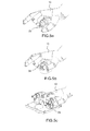
- FIGs 6a and 6b represent the hand 13 of the operator manipulating the knob 21 in rotation about a first axis 28 perpendicular to the axis 26.
- the operator pushes the index button 21 to the plate 12 or conventionally down.
- the operator pulls the index finger 21 upwards.
- the Figures 6c and 6d represent the hand 13 of the operator manipulating the knob 21 in rotation about a second axis 29 perpendicular to the axis 26 and to the axis 28.
- the operator pushes the index finger 21 to the left.
- the operator pushes the knob 21 with the thumb to the right.
- the figure 7 represents a workstation in which two operators 31 and 32 may alternatively use the same data input device 10.
- This workstation is for example the cockpit of an aircraft and the two operators 31 and 32 are the pilot and co-pilot of the aircraft.
- the data input device 10 is placed between the driver 31 and the co-pilot 32.
- the data input device 10 is ambidextrous. It can be used either by the pilot 31 or by the copilot 32.
- the pilot 31 resting on the zone 18 hidden on the figure 7 , manipulates the button 21 and the co-pilot 32, pressing on the zone 16, manipulates the button 20. Both can see access to the sphere 11 of the designator.
- buttons 20 and 21 are intended to be operated either by the same operator or by two operators arranged differently with respect to the sphere 11.
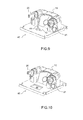
- the figure 9 represents a data input device 40 in which the designator comprises a mini-handle 41 connected to the plate 14 at one of its ends 42 by a link with two degrees of freedom in rotation.
- the movements of the mini-stick 41 enable the operator to designate an object on a computer system screen to which the mini-stick 41 is connected.
- the figure 10 represents a data input device 45 in which the designator comprises a touch surface 46 arranged in the plane than the plate 14 or slightly lowered to tactilly distinguish the contours. An operator moves a finger on the touch surface 46 to designate an object. There is also the palm rest 15 and its two buttons 20 and 21.
Abstract
L'invention concerne un dispositif d'entrée de données (10 ; 40 ; 45) comprenant un désignateur (11 ; 41 ; 46) apte à pointer une position sur un écran d'un système informatique auquel le dispositif est destiné à être raccordé et un corps (12) destiné à être fixé sur un poste de travail, le corps (12) comprenant une zone d'appui (17,18) destinée à l'appui de la main d'un opérateur (13) lorsqu'il manoeuvre le désignateur (11 ; 41 ; 46). Selon l'invention, le dispositif comprend en outre un bouton (20, 21) disposé de façon à être manoeuvré par les doigts de l'opérateur, sa main (13) restant en appui sur la zone d'appui (17,18). Le bouton (20, 21) est configuré pour permettre au moins deux sélections (23, 24, 25) distinctes de données dont un choix de valeurs dans une série et une saisie binaire en relation avec la valeur choisie.The invention relates to a data input device (10; 40; 45) comprising a designator (11; 41; 46) adapted to point a position on a screen of a computer system to which the device is intended to be connected and a body (12) intended to be fixed on a workstation, the body (12) comprising a bearing zone (17, 18) intended to support the hand of an operator (13) when maneuvering the designator (11; 41; 46). According to the invention, the device further comprises a button (20, 21) arranged to be operated by the fingers of the operator, his hand (13) resting on the support zone (17, 18). . The button (20, 21) is configured to allow at least two distinct data selections (23, 24, 25) including a choice of values in a series and a binary input in relation to the chosen value.
Description
L'invention concerne un dispositif d'entrée de données comprenant un désignateur apte à pointer une position sur un écran d'un système informatique auquel le dispositif est connecté.The invention relates to a data input device comprising a designator capable of pointing a position on a screen of a computer system to which the device is connected.
A ce jour, le désignateur le plus utilisé est une souris dont la position sur une surface plane permet à un opérateur de pointer une position sur un écran du système informatique. De nombreux autres désignateurs sont également mis en oeuvre tels que par exemple un pavé tactile (ou touchpad dans la littérature anglo-saxonne) fixé à proximité d'un clavier du système, un mini manche (ou joystick), une boule de désignation (ou track ball).To date, the most used designator is a mouse whose position on a flat surface allows an operator to point a position on a computer system screen. Many other designators are also implemented such as for example a touchpad (or touchpad in English literature) fixed near a system keyboard, a mini-stick (or joystick), a designation ball (or track ball).
Les désignateurs peuvent être regroupés en deux grandes familles, ceux possédant une partie fixe tels que la surface tactile, le mini manche et la boule de désignation et ceux ne possédant pas de partie fixe comme la souris.Designators can be grouped into two large families, those having a fixed part such as the touch surface, the mini-stick and the designation ball and those having no fixed part like the mouse.
Un désignateur permet de pointer différentes positions sur l'écran. Pour se déplacer entre deux positions, l'opérateur déplace une partie mobile du désignateur ou son doigt dans le cas du pavé tactile. Le déplacement est mesuré dans un repère orthogonal que le système informatique met en correspondance avec un repère de l'écran.A designator allows to point different positions on the screen. To move between two positions, the operator moves a moving part of the designator or his finger in the case of the touchpad. The displacement is measured in an orthogonal coordinate system that the computer system maps to a mark on the screen.
Pour améliorer l'ergonomie des désignateurs, on peut prévoir une surface d'appui, destinée à l'appui de la main de l'opérateur lorsqu'il manoeuvre le désignateur. Cette surface permet de limiter les tensions dans le poignet de l'opérateur. Pour une souris, la surface d'appui est directement formée par la forme de la souris sur laquelle l'opérateur pose la paume de la main. Pour la famille des désignateurs possédant une partie fixe, on peut prévoir un repose paume faisant partie intégrante de la partie fixe du désignateur. Le repose paume possède une forme, par exemple en portion de sphère, ce qui permet d'épouser la surface intérieure de la paume de la main.In order to improve the ergonomics of the designators, it is possible to provide a bearing surface intended to support the hand of the operator when maneuvering the designator. This surface makes it possible to limit the tensions in the wrist of the operator. For a mouse, the support surface is directly formed by the shape of the mouse on which the operator places the palm of the hand. For the family of designators having a fixed part, it is possible to provide a palm rest forming an integral part of the fixed part of the designator. The palm rest has a shape, for example in portion of sphere, which allows to marry the inner surface of the palm of the hand.
On peut associer au désignateur plusieurs boutons permettant des saisies de données comme par exemple un bouton poussoir permettant par exemple la validation d'une valeur pointée par le désignateur. Pour la famille des désignateurs possédant une partie fixe, ce type de bouton poussoir est généralement situé sur un coté du repose paume. La manoeuvre de ce bouton se fait au moyen du pouce de l'opérateur.The designator can be associated with several buttons for entering data such as a push button allowing for example the validation of a value pointed by the designator. For the family designators having a fixed part, this type of push button is usually located on one side of the palm rest. The operation of this button is done with the thumb of the operator.
A proximité du désignateur, on peut trouver des boutons rotatifs à double bague permettant notamment un réglage grossier de la valeur d'une donnée pour l'une des bagues et un réglage fin de la même valeur pour l'autre bague. Pour valider la valeur retenue, on peut utiliser le bouton de validation du désignateur. La distance séparant le bouton rotatif du bouton de validation impose à l'opérateur de déplacer sa main entre une position de sélection de la valeur sur le bouton rotatif et une position de validation sur le coté du repose paume. Plus précisément, le bouton rotatif est généralement manoeuvré entre le pouce et l'index. Le pouce doit être déplacé pour atteindre le bouton de validation.In the vicinity of the designator, it is possible to find rotary knobs with a double ring, in particular allowing a coarse adjustment of the value of a data item for one of the rings and a fine adjustment of the same value for the other ring. To validate the value selected, you can use the validation button of the designator. The distance separating the rotary knob from the validation button requires the operator to move his hand between a position for selecting the value on the rotary knob and a validation position on the side of the palm rest. More precisely, the rotary knob is generally operated between the thumb and the index finger. The thumb must be moved to reach the validation button.
De façon plus générale, les systèmes informatiques récents demandent un grand nombre d'accès pour sélectionner et valider diverses données. Ces accès nécessitent de nombreuses manoeuvres de la part de l'opérateur. Ces manoeuvres nécessitent des déplacements de sa main pour passer d'un moyen d'entrée de donnée à un autre. Ces déplacements sont ergonomiquement délicats. Tout d'abord, le fait de déplacer la main d'un bouton à un autre est source d'erreur. En suite les déplacements nécessitent un apprentissage important et même si l'opérateur les effectue rapidement, un temps de passage minimum d'un bouton à un autre est nécessaire.More generally, recent computer systems require a large number of accesses to select and validate various data. These accesses require many maneuvers on the part of the operator. These maneuvers require movements of his hand to move from one data entry means to another. These movements are ergonomically delicate. First, moving the hand from one button to another is a source of error. In the following movements require significant learning and even if the operator performs quickly, a minimum passage time from one button to another is necessary.
L'invention vise à améliorer l'ergonomie d'un dispositif d'entrée de données possédant des actionneurs multiples.The invention aims to improve the ergonomics of a data input device having multiple actuators.
A cet effet, l'invention a pour objet un dispositif d'entrée de données comprenant un désignateur apte à pointer une position sur un écran d'un système informatique auquel le dispositif est destiné à être raccordé et un corps destiné à être fixé sur un poste de travail, le corps comprenant une zone d'appui destinée à l'appui de la main d'un opérateur lorsqu'il manoeuvre le désignateur, caractérisé en ce qu'il comprend en outre un bouton disposé de façon à être manoeuvré par les doigts de l'opérateur, sa main restant en appui sur la zone d'appui, et en ce que le bouton est configuré pour permettre au moins trois sélections distinctes de données dont deux choix de valeurs, chacune dans une série et une saisie binaire en relation avec l'une des valeurs choisie.For this purpose, the subject of the invention is a data input device comprising a designator capable of pointing a position on a screen of a computer system to which the device is intended to be connected and a body intended to be fixed on a workstation, the body comprising a bearing zone intended to support the hand of an operator when maneuvering the designator, characterized in that it further comprises a button arranged to be operated by the operator's finger, his hand remaining in support on the support zone, and in that the button is configured to allow at least three distinct data selections including two choices of values, each in a series and a binary input in relation to one of the chosen values.
Dans une variante préférée, le bouton comprend une bague tournante autour d'un axe et permettant le choix de valeurs dans une série, la bague possédant une première zone et une seconde zone solidaires l'une de l'autre et ayant toutes deux une forme sensiblement tronconique s'étendant autour de l'axe sur lesquelles l'opérateur peut poser les doigts. Un plus petit diamètre de la première zone autour de l'axe est supérieur ou égal à un plus grand diamètre de la seconde zone autour de l'axe. On définit un angle au sommet α2 de la première zone et un angle au sommet α1 de la seconde zone. Les angles au sommet vérifient la relation : ![]()
![]()
L'invention sera mieux comprise et d'autres avantages apparaîtront à la lecture de la description détaillée d'un mode de réalisation donné à titre d'exemple, description illustrée par le dessin joint dans lequel :
- la
figure 1 représente un dispositif d'entrée de données conforme à l'invention : - la
figure 2 représente le dispositif de lafigure 1 manoeuvré par la main d'un opérateur ; - la
figure 3 représente une partie du dispositif permettant de visualiser un repose paume et un bouton configuré pour permettre deux ou trois saisies différentes ; - la
figure 4a et 4b représentent le bouton permettant les deux ou trois saisies ; - les
figures 5a, 5b et 5c représentent le bouton manoeuvré par la main de l'opérateur ; - les
figures 6a, 6b ,6c et 6d représentent une variante du bouton manoeuvrée par la main de l'opérateur ; - la
figure 7 représente un poste de travail dans lequel est installé un dispositif d'entrée de données ambidextre conforme à l'invention : - la
figure 8 représente la main d'un opérateur manipulant le dispositif visible sur lafigure 7 ; - les
figures 9 et 10 représentent deux variantes du dispositif d'entrée de données.
- the
figure 1 represents a data input device according to the invention: - the
figure 2 represents the device of thefigure 1 maneuvered by the hand of an operator; - the
figure 3 represents a portion of the device for displaying a palm rest and a button configured to allow two or three different entries; - the
Figure 4a and 4b represent the button allowing the two or three entries; - the
Figures 5a, 5b and 5c represent the button operated by the operator's hand; - the
Figures 6a, 6b ,6c and 6d represent a variant of the button operated by the hand of the operator; - the
figure 7 represents a workstation in which an ambidextrous data input device according to the invention is installed: - the
figure 8 represents the hand of an operator handling the visible device on thefigure 7 ; - the
Figures 9 and 10 represent two variants of the data input device.
Par souci de clarté, les mêmes éléments porteront les mêmes repères dans les différentes figures.For the sake of clarity, the same elements will bear the same references in the different figures.
La
Dans l'exemple représenté, le corps fixe comprend une plaque 12 carrée ou rectangulaire destinée à être fixée sur la planche de bord d'un aéronef. Il est bien entendu que l'invention n'est pas limitée à une utilisation dans un poste de pilotage d'un aéronef. Elle peut être mise en oeuvre dans tout autre domaine où le corps du dispositif d'entrée de données est fixé sur un poste de travail. Le corps fixe peut également comprendre un boitier situé sous la plaque 12, non représenté sur la
La
En complément du désignateur, le dispositif comprend au moins un bouton 20 disposé de façon à être manoeuvré par les doigts de l'opérateur, sa main restant en appui sur la zone d'appui. L'arc 16 possède deux extrémités, et le bouton 20 est disposé à l'une des extrémités de l'arc 16. Dans le cas d'un dispositif ambidextre, le dispositif comprend deux boutons identiques 20 et 21, le bouton 20 étant associé à la zone d'appui 17 et le bouton 21 à la zone d'appui 18. Les deux boutons 20 et 21 sont chacun disposé à l'une des extrémités de l'arc 16.In addition to the designator, the device comprises at least one
Sans changer d'appui sur le repose paume, la main 13 de l'opérateur peut manipuler le désignateur et le bouton associé à la zone d'appui considérée. Sur la
La
Dans un mode de réalisation particulier, le bouton 21 est configuré pour permettre deux choix de valeurs, chacun dans une série, la saisie binaire 25 en relation avec l'une des valeurs choisie. Dans ce mode particulier, le bouton 21 comprend deux bagues concentriques 23 et 24 sur lesquelles l'opérateur peut poser les doigts. Les bagues sont configurées chacune pour la sélection parmi un choix de valeur et un interrupteur poussoir 25 configuré pour la saisie binaire. Les bagues 23 et 24 peuvent tourner toutes deux indépendamment l'une de l'autre autour d'un même axe 26. Les bagues 23 et 24 sont avantageusement moletées ou crantées pour permettre une meilleure manipulation entre les doigts de l'opérateur. Chacune des bagues 23 et 24 entraine un commutateur rotatif permettant une sélection. Le commutateur peut comprendre plusieurs positions discrètes réparties autour de l'axe 26. Alternativement, la bague considérée peut entrainer le curseur d'un potentiomètre permettant la sélection d'une valeur de façon linéaire dans un domaine continu.In a particular embodiment, the
La bague 23 peut avoir la forme d'une rondelle sensiblement plate dont le plan est perpendiculaire à l'axe 26. D'autres formes sont bien entendu possibles, comme par exemple un tronc de cône d'axe 26 et d'angle au sommet α2 ou même une portion de cylindre. Dans le cas d'une rondelle plate, on considère que l'angle au sommet α2 est égal à 90°. Dans l'exemple représenté, la bague 24 a une forme cylindrique ou légèrement conique d'angle au sommet α1 dont le plus grand diamètre est inférieur ou égal au plus petit diamètre de la bague 23. Dans le ces d'une forme cylindrique, on considère que l'angle au sommet α2 est égal à 0°. L'angle α2 est avantageusement supérieur à l'angle α1 afin de faciliter la manoeuvre du bouton par un opérateur. Dans l'exemple représenté, le plus petit diamètre d de la bague 23 coïncide avec la plus grand diamètre de la bague 24. Les angles au sommet vérifient la relation : ![]()
![]()
Dans le mode de réalisation représenté, l'interrupteur 25 est disposé au centre de la bague 24. Il est configuré pour être manoeuvré en translation selon l'axe 26. L'interrupteur 25 possède une surface d'appui circulaire disposée au centre de la bague 24.In the embodiment shown, the
Le bouton 21 peut être associé au choix et la validation d'une seule valeur, Plus précisément la bague 23 peut permettre un réglage grossier ou défilement rapide de valeurs possibles. La bague 24 peut permettre un réglage fin ou un défilement lent autour de la valeur choisie avec la bague 23. Enfin, l'interrupteur peut permettre la validation de la valeur une fois les deux réglages, grossier et fin exécutés.The
Les
Dans le cas où le bouton 21 ne permet qu'un seul choix de valeur dans une série, on peut conserver les deux bagues 23 et 24 qui sont alors solidaires l'une de l'autre et tournent simultanément. On peut appeler cet ensemble solidaire : bague qui possède deux zones 23 et 24. L'opérateur peut utiliser la zone 23 pour faire tourner rapidement la bague (
En complément de ces trois actionneurs, le bouton 21 peut être configuré pour permettre une entrée de donnée supplémentaire au moyen d'un déplacement du bouton en rotation selon un axe perpendiculaire à l'axe 26. Autrement dit, le bouton possède une fonction mini manche ou interrupteur à bascule souvent appelé rocker. La fonction mini manche permet la sélection d'une donnée de façon linéaire dans un domaine donné et la fonction interrupteur permet la sélection d'une donnée binaire. Le bouton 21 peut être configuré pour pivoter selon un ou deux axes perpendiculaire à l'axe 26. Ces deux axes de pivotement sont perpendiculaires entre eux. Ils sont situés dans un plan positionné à la base de la bague 23.In addition to these three actuators, the
Les
Les
La
Il est bien entendu possible au pilote d'avoir accès au bouton 20, comme représenté sur la
Autrement dit, les deux boutons 20 et 21 sont destinés à être manoeuvré soit par un même opérateur soit par deux opérateurs disposés différemment par rapport à la sphère 11.In other words, the two
La
La
Claims (10)
Applications Claiming Priority (1)
| Application Number | Priority Date | Filing Date | Title |
|---|---|---|---|
| FR1400826A FR3019661B1 (en) | 2014-04-04 | 2014-04-04 | ENHANCING THE ERGONOMICS OF A DATA INPUT DEVICE |
Publications (2)
| Publication Number | Publication Date |
|---|---|
| EP2927784A1 true EP2927784A1 (en) | 2015-10-07 |
| EP2927784B1 EP2927784B1 (en) | 2020-08-05 |
Family
ID=51518809
Family Applications (1)
| Application Number | Title | Priority Date | Filing Date |
|---|---|---|---|
| EP15248039.8A Active EP2927784B1 (en) | 2014-04-04 | 2015-04-03 | Improvement of the ergonomics of a data input device |
Country Status (3)
| Country | Link |
|---|---|
| US (1) | US9939933B2 (en) |
| EP (1) | EP2927784B1 (en) |
| FR (1) | FR3019661B1 (en) |
Cited By (1)
| Publication number | Priority date | Publication date | Assignee | Title |
|---|---|---|---|---|
| FR3119601A1 (en) * | 2021-02-10 | 2022-08-12 | Airbus Helicopters | Aircraft control system and associated aircraft |
Families Citing this family (2)
| Publication number | Priority date | Publication date | Assignee | Title |
|---|---|---|---|---|
| JP6273989B2 (en) * | 2014-04-10 | 2018-02-07 | 株式会社デンソー | Operating device and vehicle |
| CN116022326B (en) * | 2023-02-13 | 2023-06-16 | 飞联智航(北京)科技有限公司 | Single-hand control handle of aircraft and control method thereof |
Citations (7)
| Publication number | Priority date | Publication date | Assignee | Title |
|---|---|---|---|---|
| EP0905645A1 (en) * | 1997-09-26 | 1999-03-31 | Honeywell Inc. | Input device and method of use |
| US6292175B1 (en) * | 2000-02-09 | 2001-09-18 | Logitech, Inc. | Ergonomic trackball device |
| US20050115816A1 (en) * | 2003-07-23 | 2005-06-02 | Neil Gelfond | Accepting user control |
| US20060012584A1 (en) * | 1998-10-26 | 2006-01-19 | Vassallo Steven P | Mechanisms for control knobs and other interface devices |
| US20090066474A1 (en) * | 2006-06-08 | 2009-03-12 | Gtoyota Jidosha Kabushiki Kaisha | Vehicle input device |
| DE102008064021A1 (en) * | 2008-12-19 | 2009-09-17 | Daimler Ag | Control unit for operation of e.g. device, in vehicle, has control element configured such that translation movement parallel to axis of rotation is realizable and movements of control element perpendicular to axis of rotation are blocked |
| FR2995103A1 (en) * | 2012-08-28 | 2014-03-07 | Ge Aviat Systems Ltd | ENTRY DEVICE |
Family Cites Families (2)
| Publication number | Priority date | Publication date | Assignee | Title |
|---|---|---|---|---|
| TW417054B (en) * | 1995-05-31 | 2001-01-01 | Sega Of America Inc | A peripheral input device with six-axis capability |
| JP4551915B2 (en) * | 2007-07-03 | 2010-09-29 | ホシデン株式会社 | Combined operation type input device |
-
2014
- 2014-04-04 FR FR1400826A patent/FR3019661B1/en not_active Expired - Fee Related
-
2015
- 2015-04-03 US US14/678,305 patent/US9939933B2/en active Active
- 2015-04-03 EP EP15248039.8A patent/EP2927784B1/en active Active
Patent Citations (7)
| Publication number | Priority date | Publication date | Assignee | Title |
|---|---|---|---|---|
| EP0905645A1 (en) * | 1997-09-26 | 1999-03-31 | Honeywell Inc. | Input device and method of use |
| US20060012584A1 (en) * | 1998-10-26 | 2006-01-19 | Vassallo Steven P | Mechanisms for control knobs and other interface devices |
| US6292175B1 (en) * | 2000-02-09 | 2001-09-18 | Logitech, Inc. | Ergonomic trackball device |
| US20050115816A1 (en) * | 2003-07-23 | 2005-06-02 | Neil Gelfond | Accepting user control |
| US20090066474A1 (en) * | 2006-06-08 | 2009-03-12 | Gtoyota Jidosha Kabushiki Kaisha | Vehicle input device |
| DE102008064021A1 (en) * | 2008-12-19 | 2009-09-17 | Daimler Ag | Control unit for operation of e.g. device, in vehicle, has control element configured such that translation movement parallel to axis of rotation is realizable and movements of control element perpendicular to axis of rotation are blocked |
| FR2995103A1 (en) * | 2012-08-28 | 2014-03-07 | Ge Aviat Systems Ltd | ENTRY DEVICE |
Cited By (3)
| Publication number | Priority date | Publication date | Assignee | Title |
|---|---|---|---|---|
| FR3119601A1 (en) * | 2021-02-10 | 2022-08-12 | Airbus Helicopters | Aircraft control system and associated aircraft |
| EP4043341A1 (en) | 2021-02-10 | 2022-08-17 | Airbus Helicopters | Aircraft control system and associated aircraft |
| US11820491B2 (en) | 2021-02-10 | 2023-11-21 | Airbus Helicopters | Aircraft control system and associated aircraft |
Also Published As
| Publication number | Publication date |
|---|---|
| US9939933B2 (en) | 2018-04-10 |
| US20150286291A1 (en) | 2015-10-08 |
| FR3019661A1 (en) | 2015-10-09 |
| FR3019661B1 (en) | 2017-07-14 |
| EP2927784B1 (en) | 2020-08-05 |
Similar Documents
| Publication | Publication Date | Title |
|---|---|---|
| EP0791868B1 (en) | Data input means for electronic device handling said data and wristwatch equipped with same | |
| EP2927784B1 (en) | Improvement of the ergonomics of a data input device | |
| CA2603852C (en) | System for assisting the ground navigation of an aeroplane in an airport | |
| EP1235136A1 (en) | Aircraft dialog device for interacting with an aircraft system | |
| FR2998048A1 (en) | HAPTIC AIR TOUCH SCREEN AND METHOD FOR OPERATING THE SAME | |
| EP2715507B1 (en) | Mission system adapted for use in a strongly disturbed environment perturbed by movements of the carrier | |
| EP1443301A2 (en) | Steerable feeler head | |
| WO2010046556A2 (en) | Mouse with six movement axes | |
| WO2010009841A2 (en) | Interface system for inputting a character sequence | |
| EP3574389A1 (en) | Pointing device and manufacturing method thereof | |
| FR3026203A1 (en) | MULTIMODE DATA INPUT SYSTEM | |
| EP1437641B1 (en) | Haptic interface device of the ground-based type comprising at least two separate rotary digital actuators | |
| FR3011951A1 (en) | DESIGNER COMPRISING A REFIT ERGONOMIC PALM | |
| WO2011015752A1 (en) | Digital display device, in particular for preparing a path | |
| TWI616781B (en) | Mouse with adjustable sensor module | |
| WO2015014945A1 (en) | Programming system for a situation analysis system on board a carrier comprising at least one onboard listening system | |
| CA2820143C (en) | Ergonomic frame for tactile command interface and related command interfaces | |
| WO2004081696A2 (en) | Joystick provided with an axis of rotation between two handles | |
| FR3077896A1 (en) | METHOD FOR CONFIGURING A MOUSE COMPRISING AT LEAST FOUR AXES | |
| FR2861473A1 (en) | BI-DIMENSIONAL POINTING DEVICE | |
| FR3011950A1 (en) | IMPROVING THE ERGONOMICS OF A DESIGNER | |
| WO2022136771A1 (en) | Human-machine interface, in particular for a vehicle or for a device | |
| FR3122649A3 (en) | Cursor control device of a graphical user interface of a flight unit | |
| FR2852442A1 (en) | Multi-axis robot control casing, has push button operated by hand, and two distinct series of control switches controlling displacement of one part of robot translating along one direction or in rotation around geometrical axis | |
| FR2976689A1 (en) | Joystick for controlling displacement and displacement rate of moving object in professional machine e.g. crane, has sensor transmitting control signal of movable object to connector based on speed of rotation of wheel |
Legal Events
| Date | Code | Title | Description |
|---|---|---|---|
| PUAI | Public reference made under article 153(3) epc to a published international application that has entered the european phase |
Free format text: ORIGINAL CODE: 0009012 |
|
| AK | Designated contracting states |
Kind code of ref document: A1 Designated state(s): AL AT BE BG CH CY CZ DE DK EE ES FI FR GB GR HR HU IE IS IT LI LT LU LV MC MK MT NL NO PL PT RO RS SE SI SK SM TR |
|
| AX | Request for extension of the european patent |
Extension state: BA ME |
|
| 17P | Request for examination filed |
Effective date: 20160406 |
|
| RBV | Designated contracting states (corrected) |
Designated state(s): AL AT BE BG CH CY CZ DE DK EE ES FI FR GB GR HR HU IE IS IT LI LT LU LV MC MK MT NL NO PL PT RO RS SE SI SK SM TR |
|
| STAA | Information on the status of an ep patent application or granted ep patent |
Free format text: STATUS: EXAMINATION IS IN PROGRESS |
|
| 17Q | First examination report despatched |
Effective date: 20170918 |
|
| GRAJ | Information related to disapproval of communication of intention to grant by the applicant or resumption of examination proceedings by the epo deleted |
Free format text: ORIGINAL CODE: EPIDOSDIGR1 |
|
| STAA | Information on the status of an ep patent application or granted ep patent |
Free format text: STATUS: GRANT OF PATENT IS INTENDED |
|
| GRAP | Despatch of communication of intention to grant a patent |
Free format text: ORIGINAL CODE: EPIDOSNIGR1 |
|
| INTG | Intention to grant announced |
Effective date: 20200506 |
|
| GRAS | Grant fee paid |
Free format text: ORIGINAL CODE: EPIDOSNIGR3 |
|
| GRAA | (expected) grant |
Free format text: ORIGINAL CODE: 0009210 |
|
| STAA | Information on the status of an ep patent application or granted ep patent |
Free format text: STATUS: THE PATENT HAS BEEN GRANTED |
|
| AK | Designated contracting states |
Kind code of ref document: B1 Designated state(s): AL AT BE BG CH CY CZ DE DK EE ES FI FR GB GR HR HU IE IS IT LI LT LU LV MC MK MT NL NO PL PT RO RS SE SI SK SM TR |
|
| REG | Reference to a national code |
Ref country code: GB Ref legal event code: FG4D Free format text: NOT ENGLISH |
|
| REG | Reference to a national code |
Ref country code: CH Ref legal event code: EP |
|
| REG | Reference to a national code |
Ref country code: AT Ref legal event code: REF Ref document number: 1299634 Country of ref document: AT Kind code of ref document: T Effective date: 20200815 |
|
| REG | Reference to a national code |
Ref country code: DE Ref legal event code: R096 Ref document number: 602015056844 Country of ref document: DE |
|
| REG | Reference to a national code |
Ref country code: IE Ref legal event code: FG4D Free format text: LANGUAGE OF EP DOCUMENT: FRENCH |
|
| REG | Reference to a national code |
Ref country code: LT Ref legal event code: MG4D |
|
| REG | Reference to a national code |
Ref country code: NL Ref legal event code: MP Effective date: 20200805 |
|
| REG | Reference to a national code |
Ref country code: AT Ref legal event code: MK05 Ref document number: 1299634 Country of ref document: AT Kind code of ref document: T Effective date: 20200805 |
|
| PG25 | Lapsed in a contracting state [announced via postgrant information from national office to epo] |
Ref country code: HR Free format text: LAPSE BECAUSE OF FAILURE TO SUBMIT A TRANSLATION OF THE DESCRIPTION OR TO PAY THE FEE WITHIN THE PRESCRIBED TIME-LIMIT Effective date: 20200805 Ref country code: SE Free format text: LAPSE BECAUSE OF FAILURE TO SUBMIT A TRANSLATION OF THE DESCRIPTION OR TO PAY THE FEE WITHIN THE PRESCRIBED TIME-LIMIT Effective date: 20200805 Ref country code: AT Free format text: LAPSE BECAUSE OF FAILURE TO SUBMIT A TRANSLATION OF THE DESCRIPTION OR TO PAY THE FEE WITHIN THE PRESCRIBED TIME-LIMIT Effective date: 20200805 Ref country code: BG Free format text: LAPSE BECAUSE OF FAILURE TO SUBMIT A TRANSLATION OF THE DESCRIPTION OR TO PAY THE FEE WITHIN THE PRESCRIBED TIME-LIMIT Effective date: 20201105 Ref country code: LT Free format text: LAPSE BECAUSE OF FAILURE TO SUBMIT A TRANSLATION OF THE DESCRIPTION OR TO PAY THE FEE WITHIN THE PRESCRIBED TIME-LIMIT Effective date: 20200805 Ref country code: ES Free format text: LAPSE BECAUSE OF FAILURE TO SUBMIT A TRANSLATION OF THE DESCRIPTION OR TO PAY THE FEE WITHIN THE PRESCRIBED TIME-LIMIT Effective date: 20200805 Ref country code: PT Free format text: LAPSE BECAUSE OF FAILURE TO SUBMIT A TRANSLATION OF THE DESCRIPTION OR TO PAY THE FEE WITHIN THE PRESCRIBED TIME-LIMIT Effective date: 20201207 Ref country code: FI Free format text: LAPSE BECAUSE OF FAILURE TO SUBMIT A TRANSLATION OF THE DESCRIPTION OR TO PAY THE FEE WITHIN THE PRESCRIBED TIME-LIMIT Effective date: 20200805 Ref country code: GR Free format text: LAPSE BECAUSE OF FAILURE TO SUBMIT A TRANSLATION OF THE DESCRIPTION OR TO PAY THE FEE WITHIN THE PRESCRIBED TIME-LIMIT Effective date: 20201106 Ref country code: NO Free format text: LAPSE BECAUSE OF FAILURE TO SUBMIT A TRANSLATION OF THE DESCRIPTION OR TO PAY THE FEE WITHIN THE PRESCRIBED TIME-LIMIT Effective date: 20201105 |
|
| PG25 | Lapsed in a contracting state [announced via postgrant information from national office to epo] |
Ref country code: NL Free format text: LAPSE BECAUSE OF FAILURE TO SUBMIT A TRANSLATION OF THE DESCRIPTION OR TO PAY THE FEE WITHIN THE PRESCRIBED TIME-LIMIT Effective date: 20200805 Ref country code: LV Free format text: LAPSE BECAUSE OF FAILURE TO SUBMIT A TRANSLATION OF THE DESCRIPTION OR TO PAY THE FEE WITHIN THE PRESCRIBED TIME-LIMIT Effective date: 20200805 Ref country code: RS Free format text: LAPSE BECAUSE OF FAILURE TO SUBMIT A TRANSLATION OF THE DESCRIPTION OR TO PAY THE FEE WITHIN THE PRESCRIBED TIME-LIMIT Effective date: 20200805 Ref country code: PL Free format text: LAPSE BECAUSE OF FAILURE TO SUBMIT A TRANSLATION OF THE DESCRIPTION OR TO PAY THE FEE WITHIN THE PRESCRIBED TIME-LIMIT Effective date: 20200805 Ref country code: IS Free format text: LAPSE BECAUSE OF FAILURE TO SUBMIT A TRANSLATION OF THE DESCRIPTION OR TO PAY THE FEE WITHIN THE PRESCRIBED TIME-LIMIT Effective date: 20201205 |
|
| PG25 | Lapsed in a contracting state [announced via postgrant information from national office to epo] |
Ref country code: CZ Free format text: LAPSE BECAUSE OF FAILURE TO SUBMIT A TRANSLATION OF THE DESCRIPTION OR TO PAY THE FEE WITHIN THE PRESCRIBED TIME-LIMIT Effective date: 20200805 Ref country code: DK Free format text: LAPSE BECAUSE OF FAILURE TO SUBMIT A TRANSLATION OF THE DESCRIPTION OR TO PAY THE FEE WITHIN THE PRESCRIBED TIME-LIMIT Effective date: 20200805 Ref country code: EE Free format text: LAPSE BECAUSE OF FAILURE TO SUBMIT A TRANSLATION OF THE DESCRIPTION OR TO PAY THE FEE WITHIN THE PRESCRIBED TIME-LIMIT Effective date: 20200805 Ref country code: SM Free format text: LAPSE BECAUSE OF FAILURE TO SUBMIT A TRANSLATION OF THE DESCRIPTION OR TO PAY THE FEE WITHIN THE PRESCRIBED TIME-LIMIT Effective date: 20200805 Ref country code: RO Free format text: LAPSE BECAUSE OF FAILURE TO SUBMIT A TRANSLATION OF THE DESCRIPTION OR TO PAY THE FEE WITHIN THE PRESCRIBED TIME-LIMIT Effective date: 20200805 |
|
| REG | Reference to a national code |
Ref country code: DE Ref legal event code: R097 Ref document number: 602015056844 Country of ref document: DE |
|
| PG25 | Lapsed in a contracting state [announced via postgrant information from national office to epo] |
Ref country code: AL Free format text: LAPSE BECAUSE OF FAILURE TO SUBMIT A TRANSLATION OF THE DESCRIPTION OR TO PAY THE FEE WITHIN THE PRESCRIBED TIME-LIMIT Effective date: 20200805 |
|
| PLBE | No opposition filed within time limit |
Free format text: ORIGINAL CODE: 0009261 |
|
| STAA | Information on the status of an ep patent application or granted ep patent |
Free format text: STATUS: NO OPPOSITION FILED WITHIN TIME LIMIT |
|
| PG25 | Lapsed in a contracting state [announced via postgrant information from national office to epo] |
Ref country code: SK Free format text: LAPSE BECAUSE OF FAILURE TO SUBMIT A TRANSLATION OF THE DESCRIPTION OR TO PAY THE FEE WITHIN THE PRESCRIBED TIME-LIMIT Effective date: 20200805 |
|
| 26N | No opposition filed |
Effective date: 20210507 |
|
| PG25 | Lapsed in a contracting state [announced via postgrant information from national office to epo] |
Ref country code: SI Free format text: LAPSE BECAUSE OF FAILURE TO SUBMIT A TRANSLATION OF THE DESCRIPTION OR TO PAY THE FEE WITHIN THE PRESCRIBED TIME-LIMIT Effective date: 20200805 |
|
| PG25 | Lapsed in a contracting state [announced via postgrant information from national office to epo] |
Ref country code: MC Free format text: LAPSE BECAUSE OF FAILURE TO SUBMIT A TRANSLATION OF THE DESCRIPTION OR TO PAY THE FEE WITHIN THE PRESCRIBED TIME-LIMIT Effective date: 20200805 |
|
| PG25 | Lapsed in a contracting state [announced via postgrant information from national office to epo] |
Ref country code: LU Free format text: LAPSE BECAUSE OF NON-PAYMENT OF DUE FEES Effective date: 20210403 |
|
| PG25 | Lapsed in a contracting state [announced via postgrant information from national office to epo] |
Ref country code: LI Free format text: LAPSE BECAUSE OF NON-PAYMENT OF DUE FEES Effective date: 20210430 Ref country code: CH Free format text: LAPSE BECAUSE OF NON-PAYMENT OF DUE FEES Effective date: 20210430 |
|
| PG25 | Lapsed in a contracting state [announced via postgrant information from national office to epo] |
Ref country code: IE Free format text: LAPSE BECAUSE OF NON-PAYMENT OF DUE FEES Effective date: 20210403 |
|
| PG25 | Lapsed in a contracting state [announced via postgrant information from national office to epo] |
Ref country code: IS Free format text: LAPSE BECAUSE OF FAILURE TO SUBMIT A TRANSLATION OF THE DESCRIPTION OR TO PAY THE FEE WITHIN THE PRESCRIBED TIME-LIMIT Effective date: 20201205 |
|
| PGFP | Annual fee paid to national office [announced via postgrant information from national office to epo] |
Ref country code: FR Payment date: 20230328 Year of fee payment: 9 |
|
| PG25 | Lapsed in a contracting state [announced via postgrant information from national office to epo] |
Ref country code: HU Free format text: LAPSE BECAUSE OF FAILURE TO SUBMIT A TRANSLATION OF THE DESCRIPTION OR TO PAY THE FEE WITHIN THE PRESCRIBED TIME-LIMIT; INVALID AB INITIO Effective date: 20150403 |
|
| PGFP | Annual fee paid to national office [announced via postgrant information from national office to epo] |
Ref country code: GB Payment date: 20230316 Year of fee payment: 9 Ref country code: BE Payment date: 20230315 Year of fee payment: 9 |
|
| P01 | Opt-out of the competence of the unified patent court (upc) registered |
Effective date: 20230427 |
|
| PG25 | Lapsed in a contracting state [announced via postgrant information from national office to epo] |
Ref country code: CY Free format text: LAPSE BECAUSE OF FAILURE TO SUBMIT A TRANSLATION OF THE DESCRIPTION OR TO PAY THE FEE WITHIN THE PRESCRIBED TIME-LIMIT Effective date: 20200805 |
|
| PGFP | Annual fee paid to national office [announced via postgrant information from national office to epo] |
Ref country code: IT Payment date: 20230328 Year of fee payment: 9 Ref country code: DE Payment date: 20230314 Year of fee payment: 9 |