EP2927681A1 - Vorrichtung zur extraktion und analyse von gasen - Google Patents
Vorrichtung zur extraktion und analyse von gasen Download PDFInfo
- Publication number
- EP2927681A1 EP2927681A1 EP15161657.0A EP15161657A EP2927681A1 EP 2927681 A1 EP2927681 A1 EP 2927681A1 EP 15161657 A EP15161657 A EP 15161657A EP 2927681 A1 EP2927681 A1 EP 2927681A1
- Authority
- EP
- European Patent Office
- Prior art keywords
- gas
- extractor
- module
- sample gas
- injector
- Prior art date
- Legal status (The legal status is an assumption and is not a legal conclusion. Google has not performed a legal analysis and makes no representation as to the accuracy of the status listed.)
- Granted
Links
- 238000000605 extraction Methods 0.000 title claims abstract description 96
- 239000007789 gas Substances 0.000 title claims description 315
- 238000004458 analytical method Methods 0.000 title claims description 16
- 239000012528 membrane Substances 0.000 claims abstract description 53
- 239000007788 liquid Substances 0.000 claims abstract description 28
- 238000000926 separation method Methods 0.000 claims description 27
- 239000012159 carrier gas Substances 0.000 claims description 25
- 239000004809 Teflon Substances 0.000 claims description 10
- 229920006362 Teflon® Polymers 0.000 claims description 10
- 239000004205 dimethyl polysiloxane Substances 0.000 claims description 8
- 229920000435 poly(dimethylsiloxane) Polymers 0.000 claims description 8
- 238000011144 upstream manufacturing Methods 0.000 claims description 8
- 238000010438 heat treatment Methods 0.000 claims description 7
- -1 polytetrafluoroethylene Polymers 0.000 claims description 6
- 230000004044 response Effects 0.000 claims description 5
- 239000012530 fluid Substances 0.000 claims description 4
- 229920001343 polytetrafluoroethylene Polymers 0.000 claims description 4
- 239000004810 polytetrafluoroethylene Substances 0.000 claims description 4
- YCKRFDGAMUMZLT-UHFFFAOYSA-N Fluorine atom Chemical compound [F] YCKRFDGAMUMZLT-UHFFFAOYSA-N 0.000 claims description 3
- 229910052731 fluorine Inorganic materials 0.000 claims description 3
- 239000011737 fluorine Substances 0.000 claims description 3
- 229920000642 polymer Polymers 0.000 claims description 2
- 210000004379 membrane Anatomy 0.000 description 42
- 238000002347 injection Methods 0.000 description 34
- 239000007924 injection Substances 0.000 description 34
- 239000003921 oil Substances 0.000 description 24
- 239000000306 component Substances 0.000 description 18
- 238000000034 method Methods 0.000 description 15
- 230000008569 process Effects 0.000 description 13
- 238000005259 measurement Methods 0.000 description 10
- XKRFYHLGVUSROY-UHFFFAOYSA-N Argon Chemical compound [Ar] XKRFYHLGVUSROY-UHFFFAOYSA-N 0.000 description 8
- 108091006146 Channels Proteins 0.000 description 7
- 238000013461 design Methods 0.000 description 5
- 239000000463 material Substances 0.000 description 5
- 229910052786 argon Inorganic materials 0.000 description 4
- 230000008878 coupling Effects 0.000 description 4
- 238000010168 coupling process Methods 0.000 description 4
- 238000005859 coupling reaction Methods 0.000 description 4
- 238000009792 diffusion process Methods 0.000 description 4
- 238000004868 gas analysis Methods 0.000 description 4
- 238000009434 installation Methods 0.000 description 4
- 238000012544 monitoring process Methods 0.000 description 4
- TZCXTZWJZNENPQ-UHFFFAOYSA-L barium sulfate Chemical compound [Ba+2].[O-]S([O-])(=O)=O TZCXTZWJZNENPQ-UHFFFAOYSA-L 0.000 description 3
- 230000008901 benefit Effects 0.000 description 3
- 230000015572 biosynthetic process Effects 0.000 description 3
- 238000001816 cooling Methods 0.000 description 3
- 238000012423 maintenance Methods 0.000 description 3
- 230000035699 permeability Effects 0.000 description 3
- 238000009530 blood pressure measurement Methods 0.000 description 2
- 238000009529 body temperature measurement Methods 0.000 description 2
- 239000003638 chemical reducing agent Substances 0.000 description 2
- 238000010276 construction Methods 0.000 description 2
- 238000010586 diagram Methods 0.000 description 2
- 238000011010 flushing procedure Methods 0.000 description 2
- 230000006870 function Effects 0.000 description 2
- 230000003993 interaction Effects 0.000 description 2
- 238000004519 manufacturing process Methods 0.000 description 2
- 239000002184 metal Substances 0.000 description 2
- 238000012856 packing Methods 0.000 description 2
- 239000004033 plastic Substances 0.000 description 2
- 239000010409 thin film Substances 0.000 description 2
- 238000009423 ventilation Methods 0.000 description 2
- YXHKONLOYHBTNS-UHFFFAOYSA-N Diazomethane Chemical class C=[N+]=[N-] YXHKONLOYHBTNS-UHFFFAOYSA-N 0.000 description 1
- 238000005033 Fourier transform infrared spectroscopy Methods 0.000 description 1
- 108090000862 Ion Channels Proteins 0.000 description 1
- 102000004310 Ion Channels Human genes 0.000 description 1
- 238000009835 boiling Methods 0.000 description 1
- 238000006243 chemical reaction Methods 0.000 description 1
- 238000004587 chromatography analysis Methods 0.000 description 1
- 238000004140 cleaning Methods 0.000 description 1
- 230000001427 coherent effect Effects 0.000 description 1
- 238000004891 communication Methods 0.000 description 1
- 238000011109 contamination Methods 0.000 description 1
- 239000008358 core component Substances 0.000 description 1
- 238000012937 correction Methods 0.000 description 1
- 238000010790 dilution Methods 0.000 description 1
- 239000012895 dilution Substances 0.000 description 1
- 238000005516 engineering process Methods 0.000 description 1
- 230000007613 environmental effect Effects 0.000 description 1
- 239000002360 explosive Substances 0.000 description 1
- 238000000855 fermentation Methods 0.000 description 1
- 230000004151 fermentation Effects 0.000 description 1
- 230000006872 improvement Effects 0.000 description 1
- 238000011065 in-situ storage Methods 0.000 description 1
- 230000001404 mediated effect Effects 0.000 description 1
- 238000006063 methoxycarbonylation reaction Methods 0.000 description 1
- 239000000203 mixture Substances 0.000 description 1
- 229910052756 noble gas Inorganic materials 0.000 description 1
- 230000003287 optical effect Effects 0.000 description 1
- 239000002861 polymer material Substances 0.000 description 1
- 238000010926 purge Methods 0.000 description 1
- 230000009467 reduction Effects 0.000 description 1
- 230000035945 sensitivity Effects 0.000 description 1
- 239000000243 solution Substances 0.000 description 1
- 238000001179 sorption measurement Methods 0.000 description 1
- 229910001220 stainless steel Inorganic materials 0.000 description 1
- 239000010935 stainless steel Substances 0.000 description 1
- 239000000126 substance Substances 0.000 description 1
- 238000012549 training Methods 0.000 description 1
- 238000012546 transfer Methods 0.000 description 1
- 230000009466 transformation Effects 0.000 description 1
- 230000007704 transition Effects 0.000 description 1
- 239000002918 waste heat Substances 0.000 description 1
Images


Classifications
-
- G—PHYSICS
- G01—MEASURING; TESTING
- G01N—INVESTIGATING OR ANALYSING MATERIALS BY DETERMINING THEIR CHEMICAL OR PHYSICAL PROPERTIES
- G01N30/00—Investigating or analysing materials by separation into components using adsorption, absorption or similar phenomena or using ion-exchange, e.g. chromatography or field flow fractionation
- G01N30/02—Column chromatography
- G01N30/60—Construction of the column
- G01N30/6095—Micromachined or nanomachined, e.g. micro- or nanosize
-
- G—PHYSICS
- G01—MEASURING; TESTING
- G01N—INVESTIGATING OR ANALYSING MATERIALS BY DETERMINING THEIR CHEMICAL OR PHYSICAL PROPERTIES
- G01N30/00—Investigating or analysing materials by separation into components using adsorption, absorption or similar phenomena or using ion-exchange, e.g. chromatography or field flow fractionation
- G01N30/02—Column chromatography
- G01N30/04—Preparation or injection of sample to be analysed
- G01N30/06—Preparation
-
- G—PHYSICS
- G01—MEASURING; TESTING
- G01N—INVESTIGATING OR ANALYSING MATERIALS BY DETERMINING THEIR CHEMICAL OR PHYSICAL PROPERTIES
- G01N30/00—Investigating or analysing materials by separation into components using adsorption, absorption or similar phenomena or using ion-exchange, e.g. chromatography or field flow fractionation
- G01N30/02—Column chromatography
- G01N30/88—Integrated analysis systems specially adapted therefor, not covered by a single one of the groups G01N30/04 - G01N30/86
-
- G—PHYSICS
- G01—MEASURING; TESTING
- G01N—INVESTIGATING OR ANALYSING MATERIALS BY DETERMINING THEIR CHEMICAL OR PHYSICAL PROPERTIES
- G01N33/00—Investigating or analysing materials by specific methods not covered by groups G01N1/00 - G01N31/00
- G01N33/26—Oils; Viscous liquids; Paints; Inks
- G01N33/28—Oils, i.e. hydrocarbon liquids
- G01N33/2835—Specific substances contained in the oils or fuels
- G01N33/2841—Gas in oils, e.g. hydrogen in insulating oils
-
- G—PHYSICS
- G01—MEASURING; TESTING
- G01N—INVESTIGATING OR ANALYSING MATERIALS BY DETERMINING THEIR CHEMICAL OR PHYSICAL PROPERTIES
- G01N30/00—Investigating or analysing materials by separation into components using adsorption, absorption or similar phenomena or using ion-exchange, e.g. chromatography or field flow fractionation
- G01N30/02—Column chromatography
- G01N30/04—Preparation or injection of sample to be analysed
- G01N30/06—Preparation
- G01N2030/062—Preparation extracting sample from raw material
-
- G—PHYSICS
- G01—MEASURING; TESTING
- G01N—INVESTIGATING OR ANALYSING MATERIALS BY DETERMINING THEIR CHEMICAL OR PHYSICAL PROPERTIES
- G01N30/00—Investigating or analysing materials by separation into components using adsorption, absorption or similar phenomena or using ion-exchange, e.g. chromatography or field flow fractionation
- G01N30/02—Column chromatography
- G01N30/04—Preparation or injection of sample to be analysed
- G01N30/06—Preparation
- G01N2030/065—Preparation using different phases to separate parts of sample
-
- G—PHYSICS
- G01—MEASURING; TESTING
- G01N—INVESTIGATING OR ANALYSING MATERIALS BY DETERMINING THEIR CHEMICAL OR PHYSICAL PROPERTIES
- G01N30/00—Investigating or analysing materials by separation into components using adsorption, absorption or similar phenomena or using ion-exchange, e.g. chromatography or field flow fractionation
- G01N30/02—Column chromatography
- G01N30/04—Preparation or injection of sample to be analysed
- G01N30/06—Preparation
- G01N30/14—Preparation by elimination of some components
- G01N2030/146—Preparation by elimination of some components using membranes
-
- G—PHYSICS
- G01—MEASURING; TESTING
- G01N—INVESTIGATING OR ANALYSING MATERIALS BY DETERMINING THEIR CHEMICAL OR PHYSICAL PROPERTIES
- G01N30/00—Investigating or analysing materials by separation into components using adsorption, absorption or similar phenomena or using ion-exchange, e.g. chromatography or field flow fractionation
- G01N30/02—Column chromatography
- G01N30/88—Integrated analysis systems specially adapted therefor, not covered by a single one of the groups G01N30/04 - G01N30/86
- G01N2030/8804—Integrated analysis systems specially adapted therefor, not covered by a single one of the groups G01N30/04 - G01N30/86 automated systems
-
- G—PHYSICS
- G01—MEASURING; TESTING
- G01N—INVESTIGATING OR ANALYSING MATERIALS BY DETERMINING THEIR CHEMICAL OR PHYSICAL PROPERTIES
- G01N30/00—Investigating or analysing materials by separation into components using adsorption, absorption or similar phenomena or using ion-exchange, e.g. chromatography or field flow fractionation
- G01N30/02—Column chromatography
- G01N30/88—Integrated analysis systems specially adapted therefor, not covered by a single one of the groups G01N30/04 - G01N30/86
- G01N2030/8809—Integrated analysis systems specially adapted therefor, not covered by a single one of the groups G01N30/04 - G01N30/86 analysis specially adapted for the sample
-
- G—PHYSICS
- G01—MEASURING; TESTING
- G01N—INVESTIGATING OR ANALYSING MATERIALS BY DETERMINING THEIR CHEMICAL OR PHYSICAL PROPERTIES
- G01N30/00—Investigating or analysing materials by separation into components using adsorption, absorption or similar phenomena or using ion-exchange, e.g. chromatography or field flow fractionation
- G01N30/02—Column chromatography
- G01N30/60—Construction of the column
- G01N30/6034—Construction of the column joining multiple columns
- G01N30/6043—Construction of the column joining multiple columns in parallel
Definitions
- the invention relates to the field of gas extraction and its analysis, in particular gas extraction and analysis of transformer gases.
- transformers are regularly sampled and analyzed.
- gas chromatographs are preferably used for gas analysis. Continuous on-site monitoring is desirable as it can help to ensure safety.
- online measuring instruments with conventional gas chromatographs are large and expensive to purchase and maintain.
- the basis of the invention is to combine a micro-technology implemented gas chromatograph module with a likewise miniaturized gas extraction module, preferably with the lowest possible dead volumes.
- the device is intended to enable a continuous analysis and monitoring of a gas content in a liquid, in particular of the oil gas content in power transformers.
- an apparatus for extracting and analyzing gas includes a gas chromatograph with a miniaturized chromatograph module arranged on a support plate Injector, a separating column connected to a heater, a detector, and a plurality of capillaries for connecting these functional parts for supply and removal of carrier gas and sample gas.
- the apparatus also includes a miniaturized gas extraction module having at least one gas extractor with a gas permeable membrane for extracting gas from a liquid through the membrane.
- the membrane forms at least one longitudinal wall of a channel in the gas extractor.
- one or more channels in the gas extractor may be formed by one or more membranes.
- the gas extraction module has a plurality of connecting lines for connecting the gas extraction module with a liquid supply and removal, as well as with an extraction gas supply and with an extraction and Probengasabbow on. Typically, extraction and sample gas removal in one line is combined.
- a sample gas discharge pipe of the gas extraction module is connected to a capillary for supplying sample gas and forms a connecting portion of a sample gas pipe.
- the connecting portion of the sample gas line between gas extraction module and injector of the chromatograph module is valve-free.
- a gas extraction module comprises a plurality of gas extractors and a plurality of corresponding connection sections of the sample gas line between the gas extraction module and the optionally also the multiple injectors of the chromatograph module, then preferably all of these connection sections of the sample gas line are valve-free.
- the combination of a miniaturized gas chromatograph and a miniaturized gas extraction module offers the advantages of miniaturization of the individual components. These are, for example, a low gas consumption (carrier gas, extraction gas, calibration gas), which allows a long service life of the device without maintenance. This in turn lowers the maintenance cost of the device.
- a low gas consumption carrier gas, extraction gas, calibration gas
- small amounts of sample gas can be analyzed.
- measuring times are usually very short (measuring cycles of a few to a few tens of minutes).
- heating a small separation column produces little waste heat, which contributes to a better overall energy balance.
- the compact design of a device made possible by the miniaturized components also makes it possible to produce a portable version of the device, as well as, in general, easy handling and installation of the device.
- the compact design is particularly advantageous in confined spaces. This is especially useful when a device needs to be permanently integrated into a possibly existing installation, as required for continuous online analysis.
- the inventive combination of gas chromatograph and gas extraction module offers further advantages.
- a valve-free connection section of the sample gas line between the gas extraction module and the chromatograph module of the gas chromatograph simplifies and not only reduces the construction of the device due to fewer components that must be installed and maintained.
- a valve-free connecting portion of the sample gas line can be shortened to a minimum and thus a dead volume of the device and a response time of the device can be minimized.
- the Device according to the invention also the integral formation of discharge and supply lines and capillaries of the same injector and gas extractor, and arranged therebetween connecting portion of the sample gas line. Depending on the design of a gas extractor so that the production of gas chromatograph module and gas extractor is possible as an integral component.
- the valve-free connection portion forms a coherent volume that can be realized, for example, as a continuous line with different diameters.
- individual line sections can be fixedly or detachably connected to one another, for example integrally formed, screwed together, clamped or welded.
- fluidics in the device according to the invention are kept very simple.
- two precision valves, as well as a pressure reducing valve for a carrier gas or extraction Qasario are needed. If the device is supplemented with a calibration gas source, this can be done via an additional pressure reducing valve, if the precision valves are designed accordingly as multiway valves (two- to three-way valve).
- the compact design and in particular the short sample gas paths allow the exploitation of the diffusion of the sample gas along the connecting portion of the sample gas line into an injection loop in the gas chromatograph module already during a measuring cycle.
- an injection loop is essentially part of the Extraction module.
- the modules for extraction and analysis are combined with one another in the device according to the invention in such a way that a gas guidance between two combined modules is simplified and shortened compared to conventional gas guidance.
- no valves in a sample gas line, in particular in the connecting portion of the sample gas line are required.
- an analysis module is already involved in a process flow if a gas extraction in the extraction module is still active.
- Miniaturized chromatographic modules as they are preferably used in the inventive device are known and are for example in the document EP 1 588 156 described in detail. It is therefore omitted to describe a miniaturized GC module in detail and it was on the document EP 1 588 156 directed.
- the basic structure of a gas chromatograph with miniaturized chromatograph module as it is preferably used in the inventive device is also, for example, in the European patent application EP 2 065 704 described.
- the components of the GC module and their interaction are described therein. Accordingly, the content of this document is deemed to be included in the present application.
- EP 2 065 704 listed a commercially available GC module is used in the gas chromatograph. As can be seen from the further illustration of the present invention, such a chromatograph module can be adapted and modified according to need and field of application.
- a gas extractor with gas-permeable membrane is used, in which the membrane forms at least one longitudinal wall of a channel in the gas extractor.
- gas and a liquid from which gas is to be extracted are passed along the channel and along the membrane through the extractor.
- the gas permeable membrane is permeable, preferably highly permeable, to the gas (s), for example transformer gases.
- gas for example transformer gases.
- liquid from which the gases are to be extracted for example transformer oil, it is poorly permeable, preferably impermeable
- Such extractors are very suitable for miniaturization.
- miniaturized gas extractors are described, as they are preferably used in the device according to the invention.
- Microreactors in which a membrane in each case forms a wall of a channel in the reactor, are so-called channel-by-channel microreaktors or, in the case of two channels, dual-channel microreators.
- An example of a dual-channel microreactor is in the publication of Maurya et al. "Continuous In Situ Generation, Separation, and Reaction of Diazomethanes in a Dual-Channel Microreactor," Angew. Chem. Int. Ed. 2011, 50, 5952ff described and shown.
- the extraction module includes at least one dual-channel microreactor.
- the at least one gas extractor has at least one tube-shaped membrane.
- a channel is formed in the extractor through the membrane.
- a variant of a gas extractor with a single tubular membrane is a so-called tube-in-tube extractor or double tube extractor.
- a gas extraction takes place via a tubular, gas-permeable, but not liquid-permeable membrane which is introduced into an outer tube, for example a metal tube or plastic tube.
- a liquid is passed between the membrane and the outer tube, while an extraction gas and the extracted gas from the liquid are guided inside the membrane.
- a basic structure of a double-tube gas extractor is, for example, in Koos et al.
- miniaturized gas extractor suitable for the device according to the invention, which has a plurality of tubular membranes in an outer tube, is a so-called "multiple tubes in a single tube" extractor.
- An example of such an extractor is the PDMSXA-2500 extraction module from MedArray, USA, with PDMS membranes which sells various such multi-tube extractors.
- a membrane used in the gas extractor is preferably permeable to several or all of these substances. If multiple gas extractors are used in the gas extraction module, they may have the same membrane or membranes that are different permeable to different gases.
- inventive device acquisition and maintenance costs compared to known Trafogasanalysevoriquesen which are based on gas chromatographic analysis methods can be reduced by preferably up to 50 percent. Furthermore, it is possible with the inventive device to obtain measurement results that are comparable to the international standards, as described for the transformation gas analysis (eg: IEC standard 60567 measuring method, standard 60599 Interpretation of the measurement results).
- the gas chromatograph has a terminal block attached to the carrier plate with carrier gas and sample gas connections for connecting carrier gas and sample gas supply lines and carrier gas and sample gas discharge lines to the capillaries.
- the gas extraction module is sealingly releasably connected directly to the terminal block of the chromatograph module.
- the sample gas outlet of the gas extraction module and the connection block can preferably be connected to one another via tube and tube connections which are preferably as short as possible and corresponding couplings, for example screwed connections.
- a sample gas outlet can also be connected directly to the terminal block via a corresponding coupling, for example an adapter.
- no additional hose or pipe connections are introduced. This allows a further reduction of dead volume and the improvement of the precision of a measurement.
- a transition and thus a possible source of error can be eliminated.
- a leak in a connector, but also in a hose itself, can be bypassed.
- the sample gas outlet of the gas extractor is integral with a connection section of the sample gas line and this in turn is connected integrally with a capillary connected thereto to the injector.
- an extraction volume is virtually integrally connected to the injector.
- Such an integral variant can for example be realized such that the at least one gas extractor and the connecting portion of the sample gas line are arranged on a common carrier plate as the GC module.
- the gas chromatograph module and the at least one gas extractor form an integral part of the device.
- Such an integral solution allows further minimization of the dead volume of the device. Also, such an integral part can be easily replaced without having to match new and existing measurement and analysis components. Also, a calibration of the integral component can be made before installation.
- a dead volume between gas extraction module and gas chromatograph is typically less than 500 microliters, preferably less than 200 microliters and, for example, less than 100 microliters.
- a dead volume is between 10 microliters and 50 microliters.
- a gas extraction module is connected in a sealingly detachable manner directly to a connection block of the chromatograph module or an extractor is integrally formed with a GC module, a dead volume is in the lower of the specified ranges of a few microliters or a few tens of microliters.
- a dead volume describes the volume in a sample gas line without membrane contact, but including an injection volume.
- Low dead volumes allow a very low response speed of the device. This can be less than 15 minutes, preferably less than 10 minutes, for example less than 5 minutes, for the device according to the invention. Small dead volumes combined with small extraction volumes result in fewer errors due to dilution and allow a faster measurement or one faster response time until a measurement result is available. A response time can be kept correspondingly short in devices with miniaturized components, as in the device according to the invention.
- this has two precision valves.
- at least one of the two precision valves upstream of the at least one gas extractor and preferably designed as a multi-way valve.
- the device according to the invention has exactly two precision valves. In a simple version, these may be simple on-off valves or, for example, two multiway valves.
- the precision valve upstream of the at least one gas extractor serves to control the supply of extraction gas into and through the gas extractor.
- the device is provided with a corresponding control, which among other things controls the actuation of the valves.
- upstream is to be understood in terms of the direction of the process flow of extraction and analysis (eg, a valve upstream of an extraction gas inlet into the extractor).
- the device has for this purpose a control, which allows a corresponding control of the valves.
- a sample gas feed into the injector is connected to a first sample gas supply capillary, for example, at the connection block of the chromatograph module.
- a sample gas supply to the injector is controlled by the control of the precision valves, thus, that sample gas from the extraction module through the first Probengaszuschreibkapillare the injector is feasible, such that the injector is unilaterally charged with sample gas.
- the sample gas in the injection loop is pressurized with extraction gas flowing through the opened valve.
- the extraction gas is under elevated pressure of preferably a few bar.
- the sample gas in the sample gas line is pushed towards the injector and initiated into the injector.
- a sample gas is substantially flushed through the sample gas line.
- a gas such as sample gas or cleaning gas
- a gas generally introduced in one direction only in the injector and (uninitiated gas) out in the same direction from the injector again.
- a one-sided injection allows injection with only one gas extractor. Fewer elements are needed and a sample gas inlet and sample gas outlet are clearly assigned.
- a one-sided injection is easy to control.
- a sample gas feed into the injector is connected to a first sample gas supply capillary and to a second sample gas supply capillary.
- a sample gas supply into the injector is controlled by the control of the precision valves, such that sample gas from the extraction module through the first and through the second Probengaszuchtkapillare the injector is feasible, such that the injector can be acted upon on both sides with sample gas.
- a Probengasabbowkapillare takes over the function of the second Probengaszuschreibkapillare for the process of injection.
- the injector is pressurized in this embodiment for the process of injection via its inlet and via its outlet and thus on both sides with pressure.
- a further gas extractor with gas-permeable membrane is preferably provided.
- Each of the two gas extractors is preceded by a precision valve, preferably a multiway valve.
- a Probengasabschreibtechnisch of a gas extractor is then connected to the first Probengaszuzenkapillare and a Probengasabschreibtechnisch the other gas extractor is connected to the second Probengaszuchtkapillare.
- both valves are opened and extraction gas is passed with positive pressure through the two extractors towards the chromatograph module.
- the sample gas in the injection loop is compressed from two sides and initiated into the injector. This fast process is essentially done by a plug flow.
- In a possible subsequent 'flushing' extraction gas is passed with overpressure in the gas cycle. The gas escapes through the membrane into the liquid. This process can be repeated several times.
- an injection with a vacuum for example a pump
- a negative pressure may be connected to a valve, for example a multiway valve, through which the sample gas is sucked through the sample gas line in the direction of negative pressure.
- the membrane contains an amorphous fluorine-containing polymer, for example polytetrafluoroethylene, preferably Teflon AF-2400 or polydimethylsiloxane (PDMS).
- amorphous fluorine-containing polymer for example polytetrafluoroethylene, preferably Teflon AF-2400 or polydimethylsiloxane (PDMS).
- Teflon AF-2400 or polydimethylsiloxane (PDMS).
- PDMS polydimethylsiloxane
- a heater for heating a liquid may be provided in the device according to the invention.
- the liquid is preferably heated before entering the extraction module.
- the heater is preferably inserted or attached in a liquid feed line upstream of the extraction module.
- a liquid is already conducted at elevated temperature in and through the or the gas extractors.
- the chromatograph module has more than one separation column and / or several injectors.
- at least one of the separation columns preferably has an occupancy of the separation column, which is different from the one or more assignments of the further separation columns. It can also all columns have mutually different assignments.
- separation columns for gas chromatographs are typically thin film or packed separation columns application.
- Different materials for a thin-film or packing material, - for the present purposes For simplicity's sake called occupancy - have, among other things, different adsorption properties.
- different separation columns have different sensitivities for different gases to be analyzed, as well as other operating characteristics. Separation columns with different assignments can thus be optimized for the analysis of certain gases. It is also possible in each case to assign a separating column to a specific gas extractor. This can then be provided with a corresponding membrane, which is for example also optimized for the extraction of certain gases.
- the inventive device can thus be extended to extended GC modules (multiple columns, multiple injectors) and advanced extraction modules (multiple gas extractors).
- the individual separation columns, injectors and gas extractors can be connected in series or in parallel as required.
- An example of separation columns and packing material for a separation column which are well suited for use in the apparatus are flexible, micro-packed separation columns, for example so-called HayeSep separation columns, as available from Hayes Separation Inc, Australia.
- the device has connections for the supply and removal of a calibration fluid for calibrating the device.
- a calibration fluid is, for example, a calibration fluid or a calibration gas.
- a calibration of the device can in principle be carried out with a calibration liquid having a defined gas content. This has the advantage that all components, including extractor and separation columns on the Based on the defined calibration liquid can be calibrated. This is passed through the device instead of the liquid otherwise to be analyzed in the device. This gives a calibration value for the device directly (without correction factors). If a calibration gas is used for the calibration. So this can be passed through the device in the same way as extraction gas. However, since the permeability characteristics of a membrane are usually different for different gases, a calibration factor corresponding to the different gases must be taken into consideration when calibrating with calibration gas.
- the device according to the invention is especially suitable for use for on-line extraction and analysis of transformer gases from transformer oil. It is preferably used for the continuous analysis of the gas content in oils of power transformers.
- the device can be installed on site and permanently connected to a transformer.
- the device according to the invention can also be used in other fields in which gas extraction from a liquid and the most cost-effective continuous gas monitoring is desired. For example, in the field of biotechnology, in fermentation processes or in the production of biogases.
- the device according to the invention is also used, for example, in the measurement of gaseous and low-boiling, liquid analytes which can not be measured with sensors.
- Fig. 1 schematically shows a combined gas extraction module 20 and chromatograph module 30 with a gas connection block 31.
- the central component of the gas chromatograph is the miniaturized Chromatographen module 30. This is constructed on a support plate 33, on which all the core components of a gas chromatograph are included. These are an electrically controlled injector 34, a thin-layer or packed separation column 35 provided with a heater, and a possibly heatable heat-conductivity detector 36 as well as a microprocessor electronics 37 for controlling the chromatograph module 30 and for evaluating, storing and transmitting the measurement data via the communication interface 32.
- various capillaries 33 are provided on the carrier plate, which connect on the one hand the injector, the separation column and the detector and on the other hand lead to the connection block 31.
- the four end portions of the capillaries inserted into the terminal block 31 are carrier gas supply capillaries 38, carrier gas discharge capillaries 39, first sample gas supply capillaries 40 and second Probengaszuchtkapillare 41, wherein the second Probengaszuchtkapillare 41 also serves as Probengasabbowkapillare.
- the same reference characters are also used accordingly for the connections in the connection block 31 for a carrier gas supply 38, for a carrier gas discharge 39, a sample gas supply 40 and a sample gas discharge 41.
- All central operating functions of the chromatograph module 30 itself can be autonomously controlled by the microprocessor electronics 37, wherein superordinate control commands can be taken over and processed by a computer (not shown).
- the microprocessor electronics 37 may also be provided with switching outputs for driving module external components such as e.g. Be equipped valves and pumps.
- Chromatograph module 30 is in the document EP 1 588 156 described in detail, so that the expert in this regard requires no further explanation. The following explanations are therefore limited to the components of the device according to the invention adapted to the coupling with the extraction module 20.
- the central components of the extraction module 20 in this embodiment are two double-tube membrane extractors 21, 22, the membrane preferably being a membrane made of Teflon AF 2400 as available from Du Pont (Wilmington, Delaware, USA).
- the schematic structure of such a double-tube membrane extractor is based on Fig. 6 and will be described below.
- An oil transfer pipeline 220 (flow direction indicated by arrows) branches off oil to be analyzed from a transformer (not shown).
- the line 220 carries the oil via an oil inlet into and through the one extractor 22, then into and through the second extractor 21, through an oil outlet from the second extractor and out of the extraction module, and back into the transformer.
- a pump 221 is provided for the continuous, preferably uniform transport of transformer oil through the extraction module 20.
- Typical oil flow rates are in the range of a few milliliters per minute (ml / min), for example in the range of 1 ml / min to 30 ml / min , preferably in the range of 2 ml / min to 20 ml / min.
- Both extractors 21, 22 are each preceded by a two-way valve 23, 24.
- a gas source (not shown), for example a noble gas pressure bottle, is connected to the two-way valves via a pressure reducing valve.
- the gas source contains the carrier gas, for example argon, which is preferably used simultaneously for extraction.
- the carrier gas is passed directly into the carrier gas inlet 38 and carrier gas outlet through the GC module 30 (carrier gas flow in 380, out 390).
- the gas 250 is passed through the valves 23,24 in the extractors 21,22.
- a gas inlet is preferably under a certain pressure, for example between 1.5 bar to 6 bar, preferably 2 bar to 4 bar.
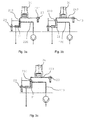
- Fig. 2a and 2b is a functional principle of the inventive device, for example according to Fig. 1 shown.
- the injector 34 is pressurized on both sides for injection of sample gas.
- the same or similar elements of the device are correspondingly provided with the same reference characters.
- the injector of the chromatograph module 30 is shown.
- Fig. 2a the sample gas formation in the extraction volume of the two extractors 21,22 is shown. Due to diffusion, the sample gas 240 dissolved from the liquid and transferred through the membrane spreads to and into the injection loop due to the short distances. In this process, the two valves 23,24 are closed for the extraction gas supply.
- the gas cycle was previously flooded with gas 250, for example argon, under pressure.
- the gas is introduced at slightly elevated pressure, for example 2bar, into the circulation. After closing the valves 23,24 argon breaks down through the membrane in the extractors 21,22 down to ambient pressure. According to the partial pressures, transformer gas is accordingly transported in the opposite direction through the membrane. Such gas transport usually lasts a few minutes and, depending on the desired measuring cycle, about 2 to 15 minutes, for example 3 to 10 minutes. After a certain time, in which sample gas has accumulated, the valves 23,24 are opened. As in Fig. 2b As shown, pressurized argon, injected from two sides, compresses the sample gas bilaterally (arrows 230). The extraction gas forces the sample gas further into the injection loop and injection into the injector 34 occurs. Top left in Fig.
- the injector is shown after pressurization but just before the injection.
- the Fig. 2b top right shows the injector 34 after the injection.
- extraction gas which can be used after closing the valves 23, 24 for purging the gas cycle.
- the injection loop extends from the connection block 31 of the chromatograph module 30, via corresponding capillaries to the injector, through the injector and back to the connection block via corresponding capillaries.
- Exemplary volumes for the injection loop are 15 to 40 microliters, for example between 20 and 30 microliters, eg 25 microliters.
- An injection volume itself in miniaturized chromatographic modules is usually a few microliters, for example about 0.5 to 10 microliters.
- the entire gas loop which is for example about 200-250 microliters, is compressed in half at the pressure of the incoming gas at 2 bar, down to about 100 to 125 microliters.
- FIG. 3a, 3b and 3c another functional principle of the inventive device is shown in which the injector 34 for injection of sample gas 240, however only on one side is pressurized.
- the same reference characters are used again for identical or similar components.
- the extraction module 20 has only one extractor 21.
- the second valve 23 is connected directly or via a corresponding hose connection to the sample gas outlet 40 of the chromatograph module 30.
- Sample gas formation in Fig. 3a is essentially the same as in Fig. 2a described, with the difference that gas diffusion into the injection loop takes place only on one side of the single extractor 21 forth.
- the valve 24 upstream of the extractor 21 is opened.
- Valve 23, downstream of the injector in the sample gas flow direction, remains closed for the injection process.
- the line can be connected via the valve 23 to a negative pressure. This can be done by a connected to the valve 23 pump 222. Support for sample gas transport is based on the one - sided principle of operation of the Fig. 3a shown, however, is also applicable to the two-sided operating principle of the device accordingly.
- FIG. 4 shows a plan view in a housing 50, for example, a plug-in module for a rack, in which housing 50, the inventive device is installed in a simple and space-saving.
- the gas extraction module 20 and the chromatograph module 30 are housed very compactly in a small area 502 of the housing 50.
- the distances d, d 'between the gas inlets and gas outlets of the two modules 20,30 in opposite and lateral direction are usually only about 1-10cm, preferably 1-5cm, in Fig. 4 for example 1-2cm.
- the short tube connections required for this are not shown.
- control valves 23,24 for the extractors, as well as the transformer oil lines 220 are arranged outside the actual modules 20,30. Outside the area 502 further components such as heating, ventilation, sensors for monitoring the device or components thereof are also housed.
- the housing 50 is provided with handles 51 and various ports for the supply and discharge of liquid to be analyzed 52, 53, supply and discharge of gases, power supply and data terminals 32.
- the housing 50 also has displays 55, on which current information or settings of a process or individual components can be displayed.
- Fig. 5 is the side view of the area 502 of the plug-in module according to Fig. 4 shown along the line AA.
- On display are the arcuate double-tube gas extractors 21, 22 with liquid inlets and outlets, as well as gas feeds 210, 211, 212, 1213.
- the GC module 30 is provided with a cooling element 42, for example a fan for cooling the module.
- Fig. 6 shows very schematically a sectional view through an arcuate double-tube extractor.
- a membrane 215, for example made of Teflon, is tubular and as centric as possible inside an outer tube 216.
- the outer tube is preferably made of metal, for example stainless steel. It can also be made of a more flexible material, such as plastic depending on the application. This is then preferably inert to the liquids and gases used in the extractor.
- a single contiguous membrane may be incorporated along the U-shape of the outer tube.
- two tubular membranes 215 are disposed along the two legs of the outer tube 216.
- the extractor has a liquid inlet 210 at one end and a liquid outlet 211 at its other end.
- the interior of the membrane is connected via a hose 214 to the terminal block 31 of the GC module.
- the extractor has suitable connecting pieces 212, 233, for example screwed connections.
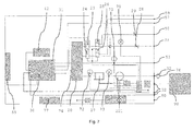
- Fig. 7 shows a block diagram for a device according to the invention, for example according to Fig. 1 or Fig. 4 , The same element are provided with the same reference numerals.
- the embodiment as in Fig. 7 has a calibration circuit and additional elements, as they can be introduced in the inventive device.
- the calibration gas circuit has a pressure reducing valve 28 in the inlet area. Upstream of the gas extractor 20 are provided in parallel to the multi-way valves 23, 24 depending on a valve 25,26 for the control of calibration gas.
Landscapes
- Chemical & Material Sciences (AREA)
- Health & Medical Sciences (AREA)
- Life Sciences & Earth Sciences (AREA)
- Biochemistry (AREA)
- Pathology (AREA)
- Immunology (AREA)
- General Physics & Mathematics (AREA)
- General Health & Medical Sciences (AREA)
- Physics & Mathematics (AREA)
- Analytical Chemistry (AREA)
- Engineering & Computer Science (AREA)
- Oil, Petroleum & Natural Gas (AREA)
- Medicinal Chemistry (AREA)
- Food Science & Technology (AREA)
- General Chemical & Material Sciences (AREA)
- Chemical Kinetics & Catalysis (AREA)
- Nanotechnology (AREA)
- Sampling And Sample Adjustment (AREA)
Abstract
Description
- Die Erfindung betrifft das Gebiet der Gasextraktion und dessen Analyse, insbesondere der Gasextraktion und Analyse von Transformatorengasen.
- Es ist bekannt, dass wenn Transformatorengase nicht überwacht und wiederaufbereitet werden, diese hochexplosive Gasgemische bilden können. Deshalb werden Transformatoren regelmässig Ölproben entnommen und analysiert. Zur Gasanalyse werden vorzugsweise Gaschromatographen verwendet. Kontinuierliche Überwachungen vor Ort sind wünschenswert, da sie zur Sicherheit beitragen können. Online-Messgeräte mit herkömmlichen Gaschromatographen sind jedoch gross und teuer in Anschaffung und Unterhalt.
- Es besteht somit Bedarf an Vorrichtungen, welche eine kontinuierliche Gasextraktion und Gasanalyse vor Ort erlauben und möglichst kostengünstig sind.
- Basis der Erfindung ist es, ein in Mikro-Technik implementiertes Gaschromatographen-Modul mit einem ebenfalls miniaturisierten Gasextraktionsmodul zu kombinieren, vorzugsweise mit möglichst geringen Totvolumina. Mit der Vorrichtung soll eine kontinuierliche Analyse und Überwachung eines Gasgehalts in einer Flüssigkeit, insbesondere des Ölgasgehalts bei Leistungstransformatoren ermöglicht werden.
- Nach einem ersten Aspekt der Erfindung wird eine Vorrichtung zum Extrahieren und Analysieren von Gas bereitgestellt. Die Vorrichtung beinhaltet einen Gaschromatograph mit einem miniaturisierten Chromatographen-Modul, welches auf einer Trägerplatte angeordnet einen Injektor, eine mit einer Heizung verbundene Trennsäule, einen Detektor, sowie mehrere Kapillaren zum Verbinden dieser Funktionsteile zur Zu- und Abfuhr von Trägergas und Probengas aufweist. Die Vorrichtung beinhaltet zudem ein miniaturisiertes Gasextraktionsmodul mit mindestens einem Gasextraktor mit einer gaspermeable Membran zum Extrahieren von Gas aus einer Flüssigkeit durch die Membran. Dabei bildet die Membran mindestens eine Längswand eines Kanals im Gasextraktor. Beispielsweise können ein oder mehrere Kanäle im Gasextraktor durch eine oder mehrere Membrane gebildet werden. Das Gasextraktionsmodul weist mehrere Anschlussleitungen zum Verbinden des Gasextraktionsmoduls mit einer Flüssigkeitszufuhr und -abfuhr, sowie mit einer Extraktionsgaszufuhr und mit einer Extraktions- und Probengasabfuhr auf. Typischerweise ist eine Extraktions- und Probengasabfuhr in einer Leitung kombiniert. Eine Probengasabfuhrleitung des Gasextraktionsmoduls ist mit einer Kapillare zur Zufuhr von Probengas verbunden und bildet einen Verbindungsabschnitt einer Probengasleitung. In der Vorrichtung gemäss vorliegender Erfindung ist der Verbindungsabschnitt der Probengasleitung zwischen Gasextraktionsmodul und Injektor des Chromatographen-Moduls ventilfrei. Beinhaltet ein Gasextraktionsmodul mehrere Gasextraktoren und mehrere entsprechende Verbindungsabschnitte der Probengasleitung zwischen dem Gasextraktionsmodul und dem oder gegebenenfalls auch den mehreren Injektoren des Chromatographen-Moduls, dann sind vorzugsweise sämtliche dieser Verbindungsabschnitte der Probengasleitung ventilfrei.
- Die Kombination eines miniaturisierten Gaschromatographen und eines miniaturisierten Gasextraktionsmoduls bietet zum einen die Vorteile der Miniaturisierung der einzelnen Komponenten. Dies sind beispielsweise ein geringer Gasverbrauch (Trägergas, Extraktionsgas, Kalibrationsgas), was eine lange Betriebsdauer der Vorrichtung ohne Unterhalt erlaubt. Dies wiederum senkt die Unterhaltskosten der Vorrichtung. Zudem können bereits kleine Probengasmengen analysiert werden. Auch sind Messzeiten in der Regel sehr kurz (Messzyklen von wenigen bis wenigen zehn Minuten). Auch erzeugt ein Aufheizen einer kleinen Trennsäule nur geringe Abwärme, was zu einem besseren Gesamtenergiehaushalt beiträgt. Der durch die miniaturisierten Komponenten ermöglichte kompakte Aufbau einer Vorrichtung erlaubt zudem das Herstellen einer portablen Ausführung der Vorrichtung, sowie allgemein eine leichte Handhabung und Installation der Vorrichtung. Der kompakte Aufbau ist insbesondere bei beengten Platzverhältnissen von Vorteil. Dies kommt vor allem dann zum Tragen, wenn eine Vorrichtung permanent in eine, eventuell bereits bestehende Installation integriert werden soll, wie dies für kontinuierliche, online Analysen erforderlich ist.
- Die erfindungsgemässe Kombination von Gaschromatograph und Gasextraktionsmodul bietet jedoch weitere Vorteile. Ein ventilfreier Verbindungsabschnitt der Probengasleitung zwischen dem Gasextraktionsmodul und dem Chromatographen-Modul des Gaschromatographen vereinfacht und vergünstigt nicht nur den Aufbau der Vorrichtung aufgrund weniger Bestandteile, die verbaut und gewartet werden müssen. Ein ventilfreier Verbindungsabschnitt der Probengasleitung kann bis auf ein Minimum verkürzt und damit ein Totvolumen der Vorrichtung und eine Ansprechzeit der Vorrichtung minimal gehalten werden. Insbesondere ermöglicht die erfindungsgemässe Vorrichtung auch das integrale Ausbilden von Ab- und Zufuhrleitungen und ebensolchen Kapillaren von Injektor und Gasextraktor, und des dazwischen angeordneten Verbindungsabschnitts der Probengasleitung. Je nach Ausgestaltung eines Gasextraktors ist damit die Fertigung von Gaschromatographen-Modul und Gasextraktor als integrales Bauteil möglich. Der ventilfreie Verbindungsabschnitt bildet ein zusammenhängendes Volumen, das beispielsweise als durchgehende Leitung mit verschiedenen Durchmessern realisierbar ist. Dabei können einzelne Leitungsabschnitte fest oder lösbar miteinander verbunden sein, beispielsweise integral geformt, miteinander verschraubt, geklemmt oder verschweisst sein.
- Generell ist eine Fluidik in der erfindungsgemässen Vorrichtung sehr einfach gehalten. In einer sehr einfachen Basisversion der Vorrichtung werden lediglich zwei Präzisionsventile, sowie ein Druckreduzierventil für eine Trägergas- oder Extraktionsqasquelle benötigt. Wird die Vorrichtung mit einer Kalibrationsgasquelle ergänzt, kann dies über ein zusätzliches Druckreduzierventil erfolgen, falls die Präzisionsventile entsprechend als Mehrwegventile (Zwei- bis Drei-Wegventil) ausgebildet sind. Die kompakte Bauweise und insbesondere die kurzen Probengaswege erlauben das Ausnutzen der Diffusion des Probengases entlang des Verbindungsabschnitts der Probengasleitung bis in einen Injektionsloop im Gaschromatographen-Modul bereits während eines Messzyklus. Aufgrund der minimal gehaltenen Wege für das Probengas zwischen Gasextraktionsmodul und Chromatographen-Modul, kombiniert mit dem bereits minimalen Weg der Kapillaren bis zum Injektor im Chromatographen-Modul, wird ein Injektionsloop im wesentlichen Teil des Extraktionsmoduls. Die Module für Extraktion und Analyse sind in der erfindungsgemässen Vorrichtung derart miteinander kombiniert, dass eine Gasführung im Vergleich zu herkömmlichen Gasführung zwischen zwei kombinierten Modulen vereinfacht und verkürzt wird. Insbesondere sind keine Ventile in einer Probengasleitung insbesondere im Verbindungsabschnitt der Probengasleitung erforderlich. Zudem ist ein Analysemodul bereits in einen Prozessablauf involviert, wenn eine Gasextraktion im Extraktionsmodul noch aktiv ist.
- Miniaturisierte Chromatographen-Module (GC-Module) wie sie in der erfindungsgemässen Vorrichtung vorzugsweise Verwendung finden sind bekannt und sind beispielsweise im Dokument
EP 1 588 156 im Detail beschrieben. Es wird deshalb darauf verzichtet ein miniaturisiertes GC-Modul im Detail zu beschreiben und es sei dazu auf das DokumentEP 1 588 156 verwiesen. Der prinzipielle Aufbau eines Gaschromatographen mit miniaturisiertem Chromatographen-Modul wie es in der erfindungsgemässen Vorrichtung vorzugsweise verwendet wird, ist zudem beispielsweise in der europäischen PatentanmeldungEP 2 065 704 beschrieben. Die Bestandteile des GC-Moduls und deren Zusammenwirken sind darin beschrieben. Entsprechend gilt der Inhalt dieser Schrift als in der vorliegenden Anmeldung aufgenommen. Wie inEP 2 065 704 aufgeführt, wird ein kommerziell erhältliches GC-Modul im Gaschromatograph verwendet. Wie aus der weiteren Darstellung der vorliegenden Erfindung hervorgeht, kann ein solches Chromatographen-Modul nach Bedarf und Anwendungsgebiet angepasst und abgeändert werden. - Für die Gasextraktion wird ein Gasextraktor mit gaspermeabler Membran verwendet, bei dem die Membran mindestens eine Längswand eines Kanals im Gasextraktor bildet. In solchen Gasextraktoren wird Gas und eine Flüssigkeit, aus der Gas extrahiert werden soll, entlang des Kanals und entlang der Membran durch den Extraktor geführt.
- Die gaspermeable Membran ist für das oder für die gewünschten Gase, beispielsweise Transformatorengase, durchlässig, vorzugsweise hochdurchlässig. Für diejenige Flüssigkeit, aus der die Gase extrahiert werden sollen, beispielsweise Transformatorenöl, ist sie jedoch gering durchlässig, vorzugsweise undurchlässig
- Solche Extraktoren eignen sich sehr gut für eine Miniaturisierung. Im folgenden sind drei Beispiele für miniaturisierte Gasextraktoren beschrieben, wie sie vorzugsweise in der Vorrichtung gemäss Erfindung verwendet werden.
- Mikroreaktoren, in welchen eine Membran jeweils eine Wand eines Kanals im Reaktor bildet, sind sogenannte ,channel by channel microreaktors' oder im Fall von zwei Kanälen, Dual-Kanal-Mikroreatoren. Ein Beispiel eines Dual-Kanal Mikroreaktors ist in der Publikation von Maurya et al. "Continous in situ generation, separation, and reaction of Diazomethane in a Dual-Channel Microreaktor", Angew. Chem. Int. Ed. 2011, 50, 5952ff beschrieben und gezeigt. In einer Ausführungsform der Vorrichtung beinhaltet das Extraktionsmodul mindestens einen Dual-Kanal Mikroreaktor.
- Gemäss einer weiteren Ausführungsform der erfindungsgemässen Vorrichtung, weist der mindestens eine Gasextraktor mindestens eine röhrenförmig angeordnete Membran auf. Dabei wird ein Kanal im Extraktor durch die Membran gebildet. Eine Variante eines Gasextraktors mit einer einzelnen röhrenförmigen Membran ist ein sogenannter Tube-in-Tube Extraktor oder Doppelrohr-Extraktor. Eine Gasextraktion geschieht darin über eine rohrförmige, gasdurchlässige, aber nicht flüssigkeitsdurchlässige Membran, die in einem Aussenrohr, beispielsweise einem Metallrohr oder Kunststoffrohr, eingebracht ist. Typischerweise wird eine Flüssigkeit zwischen Membran und Aussenrohr geführt, während ein Extraktionsgas und das extrahierte Gas aus der Flüssigkeit im Inneren der Membran geführt werden. Ein prinzipieller Aufbau eines Doppelrohr-Gasextraktors ist beispielsweise in Koos et al. 'Teflon AF-2400 mediated gas-liquid contact in continuous flow methoxycarbonylations and in-line FTIR measurement of CO concentration', Org. Biomol. Chem., 2011, 9, 6903-6908, anhand eines Doppelrohr-Gasextraktors für einen CO-Austausch über eine spezielle Teflon Membran gezeigt.
- Ein weiteres Beispiel eines für die erfindungsgemässe Vorrichtung geeigneten miniaturisierten Gasextraktors, welcher mehrere röhrenförmige Membrane in einem Aussenrohr aufweist, ist ein sogenannter "multiple tubes in a single tube"-Extraktor. Ein Beispiel für einen solchen Extraktor ist das Extraktionsmodul PDMSXA-2500 der Firma MedArray, USA, mit PDMS Membranen, welche diverse solcher Mehrfachrohr-Extraktoren vertreibt.
- Für die Extraktion von diversen Gasen haben sich speziell Membranen aus Polydimethylsiloxan (PDMS) und Polytetrafluorethylene (PTFE), letztere allgemein als Teflon bekannt, als geeignet erwiesen. Während Membrane aus PDMS vorwiegend in wässrigen Systemen Anwendung finden, haben sich gewisse Vertreter der amorphen, fluorhaltigen Polymermaterialien aufgrund ihrer Gasdurchlässigkeit und Langlebigkeit als speziell geeignet in der Verwendung zur Extraktion von Transformatorengasen erwiesen. Typische Analyte in der Analyse von Transformatorengase sind H2, N2, 02, CO, CO2, CH4, C2H2, C2H4, C2H6, C3H6, C3H8. Eine im Gasextraktor verwendete Membran ist vorzugsweise für mehrere oder alle dieser Stoffe durchlässig. Werden mehrere Gasextraktoren im Gasextraktionsmodul verwendet, können diese die gleichen Membrane aufweisen oder Membrane, die für unterschiedliche Gase unterschiedlich permeabel sind.
- In der Extraktion und Analyse von Transformatorengasen werden bis anhin keine miniaturisierten Gaschromatographen verwenden. Auch sind keine miniaturisierten Gasextraktionsmodule bekannt, welche zudem in Kombination mit miniaturisierten Gaschromatographen verwendet werden. Die Anforderung an die Geräte in solchen Anwendungen sind hoch. Insbesondere ist eine gewisse Robustheit erforderlich, da die Geräte in der Regel wechselnden Umgebungsbedingungen ausgesetzt sind. Dies gilt insbesondere für kontinuierliche online Analysen, da ein Gerät dafür vor Ort installiert ist. Auch sollten die Kosten für solche Geräte nicht zu hoch sein, da ansonsten eine möglichst flächendeckende Installation der Vorrichtungen kaum in Betracht gezogen wird.
- Mit der erfindungsgemässen Vorrichtung können Anschaffungs- und Unterhaltskosten gegenüber bekannten Trafogasanalysevorrichtungen welche auf gaschromatographischen Analysemethoden beruhen um vorzugsweise bis zu 50 Prozent gesenkt werden. Ferner ist es mit der erfindungsgemässen Vorrichtung möglich Messresultate zu erhalten, welche mit den internationalen Normen vergleichbar sind, wie sie für die Transformationsgasanalyse beschrieben sind (Bspw.: IEC Norm 60567 Messverfahren, Norm 60599 Interpretation der Messresultate).
- Gemäss einem weiteren Aspekt der Erfindung weist der Gaschromatograph ein an der Trägerplatte angebrachten Anschlussblock mit Trägergas- und Probengasanschlüssen zum Anschliessen von Trägergas- und Probengaszufuhrleitungen und Trägergas- und Probengasabfuhrleitungen an die Kapillaren auf. Dabei ist das Gasextraktionsmodul dichtend lösbar direkt an den Anschlussblock des Chromatographenmoduls angeschlossen. Dabei können Probengasauslass des Gasextraktionsmoduls und Anschlussblock über vorzugsweise möglichst kurze Schlauch- und Rohrverbindungen und entsprechende Kupplungen, beispielsweise Verschraubungen, miteinander verbunden sein. Ein Probengasauslass kann jedoch auch direkt, über eine entsprechende Kupplung, beispielsweise einen Adaptor, mit dem Anschlussblock verbunden. Zwischen Probengasauslass des Gasextraktionsmoduls und Anschlussblock sind dann keine zusätzlichen Schlauch- oder Rohrverbindungen eingebracht. Dies ermöglicht eine weitere Reduzierung von Totvolumen und die Verbesserung der Präzision einer Messung. Zudem kann ein Übergang und damit eine mögliche Fehlerquelle eliminiert werden. Eine Undichtheit in einem Verbindungsstück, aber auch in einem Schlauch selber, kann damit umgangen werden.
- Gemäss einem weiteren Aspekt der erfindungsgemässen Vorrichtung, ist der Probengasauslass des Gasextraktors integral mit einem Verbindungsabschitt der Probengasleitung und diese wiederum integral mit einer daran anschliessenden Kapillare zum Injektor verbunden. Damit ist ein Extraktionsvolumen quasi integral mit dem Injektor verbunden. Eine solch integrale Variante kann beispielsweise derart realisiert werden, dass der mindestens eine Gasextraktor und der Verbindungsabschnitt der Probengasleitung auf einer gemeinsamen Trägerplatte wie das GC-Modul angeordnet sind. Damit bildet das Gaschromatographen-Modul und der mindestens eine Gasextraktor ein integrales Bauteil der Vorrichtung.
- Eine solch integrale Lösung erlaubt eine weitere Minimierung des Totvolumens der Vorrichtung. Auch kann ein solch integrales Bauteil einfach ersetzt werden, ohne dass neue und bestehende Mess- und Analyse-Komponenten aneinander angepasst werden müssen. Auch kann eine Kalibration des integralen Bauteils bereits vor Einbau vorgenommen werden.
- In der erfindungsgemässen Vorrichtung beträgt ein Totvolumen zwischen Gasextraktionsmodul und Gaschromatograph typischerweise weniger als 500 Mikroliter, vorzugsweise weniger als 200 Mikroliter und beispielsweise weniger als 100 Mikroliter. Beispielsweise liegt ein Totvolumen zwischen 10 Mikroliter und 50 Mikroliter. Wird ein Gasextraktionsmodul dichtend lösbar direkt an einen Anschlussblock des Chromatographen-Moduls angeschlossen oder ein Extraktor integral mit einem GC-Modul ausgebildet, liegt ein Totvolumen im unteren der angegebenen Bereiche von wenigen Mikrolitern oder wenigen zehn Mikrolitern. Generell beschreibt ein Totvolumen das Volumen in einer Probengasleitung ohne Membrankontakt, aber inklusive einem Injektionsvolumen.
- Geringe Totvolumen erlauben eine sehr geringe Ansprechgeschwindigkeit der Vorrichtung. Diese kann für die erfindungsgemässe Vorrichtung weniger als 15 min, vorzugsweise weniger als 10 Minuten, beispielsweise weniger als 5 min betragen. Kleine Totvolumen kombiniert mit kleinen Extraktionsvolumen ergeben weniger Fehler aufgrund einer Verdünnung und erlauben eine schneller Messung bzw. eine schnellere Antwortzeit bis ein Messresultat erhältlich ist. Eine Ansprechzeit kann in Vorrichtungen mit miniaturisieren Komponenten, wie in der erfindungsgemässen Vorrichtung entsprechend kurz gehalten werden.
- Gemäss einem weiteren Aspekt der erfindungsgemässen Vorrichtung, weist diese zwei Präzisionsventile auf. Dabei ist mindestens eines der beiden Präzisionsventile dem mindestens einen Gasextraktor vorgeschaltet und vorzugsweise als Mehrwegventil ausgestaltet. In vorteilhaften Ausführungsformen weist die erfindungsgemässe Vorrichtung genau zwei Präzisionsventile auf. In einer einfachen Version können dies einfache Auf-Zu Ventile sein oder beispielsweise zwei Mehrwegventile. Das dem mindestens einen Gasextraktor vorgeschaltete Präzisionsventil dient zur Steuerung der Zuführung von Extraktionsgas in und durch den Gasextraktor. Die Vorrichtung ist mit einer entsprechenden Steuerung, welche unter anderem die Betätigung der Ventile steuert, versehen. Der Begriff ,vorgeschaltet' ist bezüglich der Richtung des Prozessablaufs von Extraktion und Analyse zu verstehen (m.a.W. ein Ventil ist einem Extraktionsgaseinlass in den Extraktor vorgeschaltet).
- Im folgenden werden zwei Aufbauversionen und damit verbundenen Funktionsprinzipien der Vorrichtung beschrieben. Die Vorrichtung weist dazu eine Steuerung auf, welche eine entsprechende Steuerung der Ventile erlaubt.
- Einseitiger Aufbau: Eine Probengaszuführung in den Injektor ist mit einer ersten Probengaszufuhrkapillare, beispielsweise am Anschlussblock des Chromatographen-Moduls verbunden. Eine Probengaszufuhr in den Injektor wird dabei durch die Steuerung der Präzisionsventile gesteuert, derart, dass Probengas vom Extraktionsmodul durch die erste Probengaszufuhrkapillare zum Injektor führbar ist, derart, dass der Injektor einseitig mit Probengas beaufschlagbar ist.
- Zur Injektion des Probengases in den Injektor wird das sich im Injektionsloop befindliche Probengas mit durch das geöffnete Ventil hindurchströmendem Extraktionsgas mit Druck beaufschlagt. Das Extraktionsgas steht dazu unter erhöhtem Druck von vorzugsweise wenigen bar. Das sich in der Probengasleitung befindliche Probengas wird Richtung Injektor geschoben und in den Injektor initiiert. In einer einseitigen Druckbeaufschlagung des Injektors wird ein Probengas im wesentlichen durch die Probengasleitung gespült.
- Bei einseitig mit Druck beaufschlagten Injektoren wird ein Gas, beispielsweise Probengas oder Reinigungsgas, generell nur in einer Richtung in den Injektor eingeführt und (nicht initiiertes Gas) in derselben Richtung aus dem Injektor wieder herausgeführt. Eine einseitige Injektion erlaubt eine Injektion mit nur einem Gasextraktor. Es werden weniger Elemente benötigt und ein Probengaseinlass und ein Probengasauslass sind klar zugeordnet. Zudem ist eine einseitige Injektion gut kontrollierbar.
- Zweiseitiger Aufbau: Eine Probengaszuführung in den Injektor ist mit einer ersten Probengaszufuhrkapillare und mit einer zweiten Probengaszufuhrkapillare verbunden. Eine Probengaszufuhr in den Injektor wird dabei durch die Steuerung der Präzisionsventile gesteuert, derart, dass Probengas vom Extraktionsmodul durch die ersten und durch die zweite Probengaszufuhrkapillare zum Injektor führbar ist, derart, dass der Injektor beidseitig mit Probengas beaufschlagbar ist. Eine Probengasabfuhrkapillare übernimmt dabei die Funktion der zweiten Probengaszufuhrkapillare für den Vorgang der Injektion. Der Injektor wird in dieser Ausführungsform für den Vorgang der Injektion über seinen Einlass und über seinen Auslass und somit beidseitig mit Druck beaufschlagt.
- Für eine beidseitige Druckbeaufschlagung ist vorzugsweise ein weiterer Gasextraktor mit gaspermeabler Membran vorgesehen. Dabei ist jedem der beiden Gasextraktoren ein Präzisionsventil, vorzugsweise ein Mehrwegventil, vorgeschaltet. Vorzugsweise ist dann eine Probengasabfuhrleitung des einen Gasextraktors mit der ersten Probengaszufuhrkapillare verbunden und eine Probengasabfuhrleitung des weiteren Gasextraktors ist mit der zweiten Probengaszufuhrkapillare verbunden. Für den Vorgang der Injektion werden beide Ventile geöffnet und Extraktionsgas wird mit Überdruck durch die beiden Extraktoren in Richtung Chromatographen-Modul geleitet. Das sich im Injektionsloop befindliche Probengas wird von zwei Seiten komprimiert und in den Injektor initiiert. Dieser schnelle Vorgang geschieht im wesentlichen durch eine Pfropfenströmung. Bei einer möglichen nachfolgende ,Spülung' wird Extraktionsgas mit Überdruck in den Gaskreislauf geleitet. Das Gas entweicht durch die Membran in die Flüssigkeit. Dieser Vorgang kann mehrmals wiederholt werden.
- In beiden Funktionsvarianten kann eine Injektion mit Vakuum, beispielsweise einer Pumpe, unterstützt und verbessert werden, vorzugsweise ohne dass zusätzliche Ventile benötigt werden. Dabei kann an ein Ventil, beispielsweise ein Mehrwegventil, ein Unterdruck angeschlossen sein, durch welchen das Probengas durch die Probengasleitung in Richtung Unterdruck gesaugt wird.
- Gemäss einem Aspekt der erfindungsgemässen Vorrichtung beinhaltet die Membran ein amorphes fluorhaltiges Polymer, beispielsweise Polytetrafluorethylen, vorzugsweise Teflon AF-2400 oder Polydimethylsiloxan (PDMS). Membrane aus diesen Materialien zeichnen sich durch eine sehr gute Gaspermeabilität, erstere insbesondere für Transformatorengase, aus, bei entsprechender Beständigkeit und Langlebigkeit. Vorzugsweise werden für den oder die mehreren Gasextraktoren gemäss Erfindung Membrane aus Teflon AF-2400 verwendet.
- Um eine Gasdiffusion zu erhöhen und eine Gaslöslichkeit zu verkleinern, kann in der erfindungsgemässen Vorrichtung eine Heizung zum Heizen einer Flüssigkeit vorgesehen sein. Die Flüssigkeit wird vorzugsweise vor Eintritt ins Extraktionsmodul geheizt. Die Heizung wird bevorzugt in einer Flüssigkeitszuführleitung stromaufwärts zum Extraktionsmodul ein- oder angebracht. Damit wird eine Flüssigkeit bereits mit erhöhter Temperatur in und durch den oder die Gasextraktoren geführt.
- Gemäss einem weiteren Aspekt der erfindungsgemässen Vorrichtung, weist das Chromatographen-Modul mehr als eine Trennsäule und/oder mehrere Injektoren auf. Bei mehreren Trennsäulen weist vorzugsweise mindestens eine der Trennsäulen eine Belegung der Trennsäule auf, welche zu der oder den Belegungen der weiteren Trennsäulen unterschiedlich ist. Es können auch alle Trennsäulen zueinander unterschiedliche Belegungen aufweisen.
- Als Trennsäulen für Gaschromatographen finden typischerweise Dünnschicht oder gepackte Trennsäulen Anwendung. Unterschiedliche Materialen für ein Dünnschicht- oder Packungsmaterial, - für die vorliegenden Zwecke der Einfachheit halber Belegung genannt -, weisen unter anderem unterschiedliche Adsorptionseigenschaften aus. Entsprechend unterschiedliche Trennsäulen weisen unterschiedliche Empfindlichkeiten für unterschiedliche zu analysierende Gase, sowie andere Betriebsverläufe auf. Trennsäulen mit unterschiedlichen Belegungen können somit auf die Analyse gewisser Gase optimiert werden. Auch ist es möglich jeweils eine Trennsäule einem bestimmten Gasextraktor zuzuordnen. Dieser kann dann mit einer entsprechenden Membran versehen sein, welche beispielsweise ebenfalls auf die Extraktion von bestimmten Gasen optimiert ist. Die erfindungsgemässe Vorrichtung kann somit auf erweiterte GC Module (mehrere Trennsäulen, mehrere Injektoren) und erweiterte Extraktionsmodule (mehrere Gasextraktoren) ausgebaut werden. Dabei können die einzelnen Trennsäulen, Injektoren und Gasextraktoren je nach Bedarf seriell oder parallel verschaltet sein. Ein Beispiel für Trennsäulen und ein Packungsmaterial für eine Trennsäule, die für die Verwendung in der Vorrichtung gut geeignet sind, sind flexible, mikrogepackte Trennsäulen, beispielsweise sogenannte HayeSep-Trennsäulen, wie sie von der Firma Hayes Separation Inc, Australien, erhältlich sind.
- Gemäss einem weiteren Aspekt der erfindungsgemässen Vorrichtung, weist die Vorrichtung Anschlüssen für die Zu-und Abfuhr eines Kalibrierfluids zum Kalibrieren der Vorrichtung auf. Ein Kalibrierfluid ist beispielsweise eine Kalibrierflüssigkeit oder ein Kalibriergas.
- Eine Kalibrierung der Vorrichtung kann prinzipiell mit einer Kalibrierflüssigkeit mit definiertem Gasgehalt vorgenommen werden. Dies hat den Vorteil, dass sämtliche Komponenten, inklusive Extraktor und Trennsäulen auf der Basis der definierten Kalibrierflüssigkeit kalibriert werden können. Diese wird anstelle der ansonsten in der Vorrichtung zu analysierenden Flüssigkeit durch die Vorrichtung geleitet. Dies ergibt direkt (ohne Korrekturfaktoren) einen Kalibrationswert für die Vorrichtung. Wird für die Kalibrierung ein Kalibrationsgas verwendet. So kann dieses auf dem gleichen Weg wie Extraktionsgas durch die Vorrichtung geführt werden. Da jedoch die Permeabilitätseigenschaften einer Membran in der Regel unterschiedlich ist für unterschiedliche Gase, muss bei der Kalibration mit Kalibrationsgas ein Korrekturfaktor entsprechend den unterschiedlichen Gasen mitberücksichtigt werden.
- Die erfindungsgemässe Vorrichtung ist speziell geeignet für die Verwendung zur online Extraktion und Analyse von Transformatorengasen aus Transformatorenöl. Sie wird vorzugsweise für die kontinuierliche Analyse des Gasgehalts in Ölen von Leistungstransformatoren verwendet. Die Vorrichtung kann dabei vor Ort installiert und permanent mit einem Transformator verbunden sein. Die erfindungsgemässe Vorrichtung kann jedoch auch in anderen Gebieten Verwendung finden, in denen Gasextraktion aus einer Flüssigkeit und eine möglichst kostengünstige, kontinuierliche Gasüberwachung gewünscht ist. Beispielsweise auf dem Gebiet der Biotechnologie, bei Fermentationsprozessen oder bei der Herstellung von Biogasen. Die erfindungsgemässe Vorrichtung findet beispielsweise auch Verwendung bei der Messung von gasförmigen und tiefsiedenden, flüssigen Analyten, die nicht mit Sensoren gemessen werden können.
- Weitere Details und vorteilhafte Ausgestaltungen der Erfindung ergeben sich aus der nachstehenden Beschreibung von Ausführungsbeispielen anhand der Zeichnungen. Es zeigen:
- Fig. 1
- eine blockschematische Darstellung der erfindungsgemässen Kombination von Gasextraktionseinheit und Gaschromatograph;
- Fig. 2a,2b
- eine schematische Darstellung einer ersten, 'zweiseitigen' Betriebsart der erfindungsgemässen Vorrichtung; im Zustand, in dem Probengas gebildet wird (
Fig. 2a ) und im Zustand, in dem Injektion erfolgt (Fig. 2b ); - Fig. 3a-3c
- eine schematische Darstellung einer zweiten, 'einseitigen' Betriebsart der erfindungsgemässen Vorrichtung; in den Zuständen in dem Probengas gebildet wird (
Fig. 3a ), in dem Injektion erfolgt (Fig. 3b ), und in dem der Injektionsloop gespült wird (Fig. 3c ) - Fig. 4
- eine vereinfachte technische Zeichnung einer Aufsicht in ein Gehäuse in dem die erfindungsgemässe Vorrichtung eingebaut ist;
- Fig. 5
- einen Schnitt entlang der Linie A-A in
Fig. 4 ; - Fig. 6
- eine schematische Skizze einer Schnittansicht durch einen Doppelrohr-Gasextraktor mit gaspermeabler Membran;
- Fig. 7
- ein Blockschaltbild für eine Vorrichtung beispielsweise gemäss
Fig. 1 mit zusätzlichen Kalibriergasanschlüssen. - Ausser es ist in der Anmeldung anderweitig beschrieben oder es sind für eine Fachperson abweichende Angaben offensichtlich, gelten die folgenden Definitionen:
- Probengasleitung: Gasvolumen zwischen den zwei Ventilen;
- Totvolumen: Volumen der Probengasleitung ohne Membrankanalvolumen im Gasextraktor;
- Injektionsloop: Totvolumen der Probengasleitung auf dem GC-Modul;
- Injektionsvolumen: Probengasleitung im Injektor vor Injektion.
-
Fig. 1 zeigt schematisch ein kombiniertes Gasextraktionsmodul 20 und Chromatographen-Modul 30 mit einem Gas-Anschlussblock 31. Das zentrale Bauelement des Gaschromatographen ist das miniaturisierte Chromatographen-Modul 30. Dieses ist auf einer Trägerplatte 33 aufgebaut, auf der alle Kernkomponenten eines Gaschromatographen enthalten sind. Es sind dies ein elektrisch gesteuerter Injektor 34, eine mit einer Heizung versehene Dünnschicht- oder gepackte Trennsäule 35 und ein ggf. auch beheizbarer Wärmeleitfähigkeitsdetektor 36 sowie eine Mikroprozessor-Elektronik 37 zur Steuerung des Chromatographen-Moduls 30 sowie zur Auswertung, Speicherung und Übermittlung der Messdaten über die Kommunikationsschnittstelle 32. Ferner sind auf der Trägerplatte 33 diverse Kapillaren vorgesehen, welche einerseits den Injektor, die Trennsäule und den Detektor verbinden und anderseits zum Anschlussblock 31 führen. Die in den Anschlussblock 31 eingesetzten vier Endabschnitte der Kapillaren sind Trägergaszufuhrkapillare 38, Trägergasabfuhrkapillare 39, erste Probengaszufuhrkapillare 40 und zweite Probengaszufuhrkapillare 41, wobei die zweite Probengaszufuhrkapillare 41 gleichzeitig auch als Probengasabfuhrkapillare dient. Dieselben Referenzeichen werden entsprechend auch für die Anschlüsse im Anschlussblock 31 für eine Trägergaszufuhr 38, für eine Trägergasabfuhr 39, eine Probengaszufuhr 40 und eine Probengasabfuhr 41 verwendet. - Alle zentralen Betriebsfunktionen des Chromatographen-Moduls 30 selbst können von der Mikroprozessor-Elektronik 37 autonom gesteuert werden, wobei übergeordnete Steuerbefehle von einem Rechner (nicht gezeigt) übernommen und abgearbeitet werden können. Die Mikroprozessor-Elektronik 37 kann auch mit Schalt-Ausgängen zur Ansteuerung von modul-externen Komponenten wie z.B. Ventilen und Pumpen ausgestattet sein.
- Das Chromatographen-Modul 30 ist im Dokument
EP 1 588 156 in allen Details beschrieben, so dass der Fachmann diesbezüglich keiner näheren Erläuterung bedarf. Die folgenden Ausführungen beschränken sich daher auf die an die Kopplung mit dem Extraktionsmodul 20 angepassten Komponenten der erfindungsgemässen Vorrichtung. - Die zentralen Bauteile des Extraktionsmoduls 20 sind in dieser Ausführungsform zwei Doppelrohr-Membranextraktoren 21, 22, wobei die Membran vorzugsweise ein aus Teflon AF 2400 hergestellte Membran ist, wie sie von der Firma Du Pont (Wilmington, Delaware, USA) erhältlich ist. Der schematische Aufbau eines solchen Doppelrohr-Membranextraktors ist anhand
Fig. 6 gezeigt und wird weiter unten beschrieben. Eine für den Öltransport vorgesehene Transformatorenölleitung 220 (Fliessrichtung mit Pfeilen eigezeichnet), zweigt zu analysierendes Öl von einem Transformator (nicht gezeigt) ab. Die Leitung 220 führt das Öl über einen Öleinlass in und durch den einen Extraktor 22, dann in und durch den zweiten Extraktor 21, durch einen Ölauslass aus dem zweiten Extraktor und aus dem Extraktionsmodul hinaus und wieder zurück in den Transformator. In der Transformatorenleitung 220 ist eine Pumpe 221 vorgesehen zum kontinuierlichen, vorzugsweise gleichmässigen Transport von Transformatorenöl durchs Extraktionsmodul 20. Typische Öldurchflussmengen sind im Bereich von einigen Millilitern pro Minute (ml/min), beispielsweise im Bereich von 1 ml/min bis 30 ml/min, vorzugsweise im Bereich von 2 ml/min bis 20 ml/min. - Beiden Extraktoren 21,22 ist je ein Zweiweg-Ventil 23,24 vorgeschaltet. Eine Gasquelle (nicht gezeigt), beispielsweise eine Edelgas-Druckflasche, ist über ein Druckreduzierventil mit den Zweiweg-Ventilen verbunden. Die Gasquelle beinhaltet das Trägergas, beispielsweise Argon, welches vorzugsweise gleichzeitig zur Extraktion verwendet wird. Das Trägergas wird direkt in den Trägergaseinlass 38 und Trägergasauslass durch das GC-Modul 30 geleitet (Trägergasfluss in 380, out 390). Zur Extraktion wird das Gas 250 über die Ventile 23,24 in die Extraktoren 21,22 geleitet. Ein Gaseinlass geschieht vorzugsweise unter einem bestimmten Druck, beispielsweise zwischen 1.5 bar bis 6 bar, vorzugsweise 2 bar bis 4 bar.
- Wie schon weiter vorne erläutert, ist es von besonderer Wichtigkeit, dass wenigstens die Probengas führenden Teile der Anordnung möglichst totvolumenfrei konzipiert sind. Dies wird durch die spezielle Anordnung von Extraktoren 21,22 und Anschlussblock 31 erreicht, an welchen alle gasführenden Leitungen direkt oder mittels kurzen Schlauchverbindungen, ans Chromatographen-Modul 30 angeschlossen sind. Dies ermöglicht eine allgemeine Minimierung des Verbindungsabschnitts 260 der Probengasleitung, welcher sich vom Ausgang Gasextraktor 21 über den Injektor 34 und zum Ausgang des zweiten Gasextraktors 22 erstreckt. Die gesamte Probengasleitung erstreckt sich im wesentlichen über die Strecke zwischen den zwei Ventilen 23,24 erstreckt.
- Die nahe Kopplung ermöglicht eine spezielle Wechselwirkung der Module, wie sie in anhand der folgenden zwei Funktionsprinzipien anhand der
Figuren 2a,2b und3a,3b und 3c gezeigt sind. - In den
Fig. 2a und 2b ist ein Funktionsprinzip der erfindungsgemässen Vorrichtung, beispielsweise gemässFig. 1 gezeigt. Darin wird der Injektor 34 zur Injektion von Probengas zweiseitig mit Druck beaufschlagt. Gleiche oder ähnliche Elemente der Vorrichtung sind entsprechend mit den gleichen Referenzeichen versehen. Der Übersichtlichkeit halber ist nur der Injektor des Chromatographen-Moduls 30 gezeigt. InFig. 2a ist die Probengasbildung im Extraktionsvolumen der beiden Extraktoren 21,22 dargestellt. Durch Diffusion verteilt sich das aus der Flüssigkeit gelöste und durch die Membran transferierte Probengas 240 aufgrund der kurzen Wege bis in den und im Injektionsloop. Bei diesem Prozess sind die beiden Ventile 23,24 für die Extraktionsgaszuführung geschlossen. Der Gaskreislauf wurde zuvor mit Gas 250, beispielsweise Argon, unter Druck geflutet. Das Gas wird dabei mit leicht erhöhtem Druck, beispielsweise 2bar, in den Kreislauf eingeführt. Nach Schliessen der Ventile 23,24 baut sich Argon durch die Membran in den Extraktoren 21,22 bis auf Umgebungsdruck ab. Gemäss den Partialdrücken wird entsprechend Transformatorengas in der Gegenrichtung durch die Membran transportiert. Ein solcher Gastransport dauert in der Regel wenige Minuten und beträgt je nach gewünschtem Messzyklus ca. 2 bis 15 Minuten, beispielsweise 3 bis 10 Minuten. Nach einer gewissen Zeit, in der sich Probengas angesammelt hat werden die Ventile 23,24 geöffnet. Wie inFig. 2b gezeigt, komprimiert das von zwei Seiten einschiessende, mit Druck beaufschlagte Argon das Probengas zweiseitig (Pfeile 230). Das Extraktionsgas drängt das Probengas weiter in den Injektionsloop und Injektion in den Injektor 34 erfolgt. Oben links inFig. 2b ist der Injektor nach der Druckbeaufschlagung, aber gerade noch vor der Injektion gezeigt. DieFig. 2b , oben rechts zeigt den Injektor 34 nach der Injektion. Im ,unteren' Injektionsloop fliesst Extraktionsgas, welches nach Schliessen der Ventile 23, 24 zum Spülen des Gaskreislauf genutzt werden kann. - Der Injektionsloop erstreckt sich in dieser Ausführungsform vom Anschlussblock 31 des Chromatographen-Moduls 30, über entsprechende Kapillaren zum Injektor, durch den Injektor hindurch und über entsprechende Kapillaren wieder zurück zum Anschlussblock. Beispielhafte Volumen für den Injektionsloop sind 15 bis 40 Mikroliter, beispielsweise zwischen 20 und 30 Mikroliter, z.B. 25 Mikroliter. Ein Injektionsvolumen selber beträgt in miniaturisierten Chromatographen-Modulen in der Regel wenige Mikroliter, beispielsweise etwa 0.5 bis 10 Mikroliter. Im Beispiel von
Fig. 2b wird der gesamte Gaskreislauf, der beispielsweise in etwa 200-250 Mikroliter beträgt, unter dem Druck des einströmenden Gases bei 2 bar auf die Hälfte komprimiert, bis auf etwa 100 bis 125 Mikroliter. - In den
Fig. 3a, 3b und 3c ist ein weiteres Funktionsprinzip der erfindungsgemässen Vorrichtung gezeigt, in dem der Injektor 34 zur Injektion von Probengas 240 jedoch nur einseitig mit Druck beaufschlagt wird. Für gleiche oder ähnliche Komponenten werden wiederum dieselben Referenzzeichen verwendet. Das Extraktionsmodul 20 weist nur einen Extraktor 21 auf. Das zweite Ventil 23 ist direkt oder über eine entsprechende Schlauchverbindung mit dem Probengasauslass 40 des Chromatographen-Moduls 30 verbunden. Die Probengasbildung inFig. 3a verläuft im wesentlichen gleich wie inFig. 2a beschrieben, mit dem Unterschied, dass Gasdiffusion in den Injektionsloop nur einseitig vom einzigen Extraktor 21 her erfolgt. GemässFig. 3b wird das dem Extraktor 21 vorgeschaltete Ventil 24 geöffnet. Ventil 23, dem Injektor in Probengasfliessrichtung nachgeschaltet, bleibt für den Injektionsvorgang geschlossen. Dies ist inFig. 3b gezeigt. Nach Öffnen des Ventils 24 strömt Extraktionsgas 230 mit Überdruck durch den Extraktor 21. Probengas 240 wird komprimiert und in Richtung Injektor 34 und Ventil 23 geschoben, wobei Injektion erfolgt. InFig. 3c ist der nachfolgende Spülvorgang des Gaskreislaufs gezeigt. Dazu sind beide Ventile 23,24 geöffnet und der gesamte Gaskreislauf durch den Extraktor 21 und den Injektor 34 werden von Extraktionsgas 230 durchflossen. Anschliessend an den Spülvorgang wird Ventil 23 wieder geschlossen und der Gaskreislauf hat Umgebungsdruck. - Zur Unterstützung eines Gastransports durch die Probengasleitung kann die Leitung über das Ventil 23 an einen Unterdruck angeschlossen werden. Dies kann durch ein mit dem Ventil 23 verbundene Pumpe 222 geschehen. Eine Unterstützung des Probengastransports ist anhand des einseitigen Funktionsprinzips der
Fig. 3a gezeigt, ist jedoch auch für das zweiseitige Funktionsprinzip der Vorrichtung entsprechend anwendbar. - Die technische Zeichnung gemäss
Fig. 4 zeigt eine Aufsicht in ein Gehäuse 50, beispielsweise ein Einschubmodul für ein Rack, in welchem Gehäuse 50 die erfindungsgemässe Vorrichtung einfach und platzsparend eingebaut ist. Der Übersichtlichkeit halber sind vor allem die Hauptkomponenten der Vorrichtung abgebildet. Das Gasextraktions-Modul 20 und das Chromatographen-Modul 30 sind sehr kompakt in einem kleinen Bereich 502 des Gehäuses 50 untergebracht. Zu sehen sind die nahe Anordnung der Gasauslässe 201 des Extraktionsmoduls 20 zu den Gaseinlässen und Gasauslässen 38,39,40,41 im Chromatographen-Modul 30. Die Distanzen d, d' zwischen den Gaseinlässen und Gasauslässen der beiden Module 20,30 in gegenüberliegender und seitlicher Richtung betragen in der Regel lediglich ca. 1-10cm, vorzugsweise 1-5cm, inFig. 4 beispielsweise 1-2cm. Die kurzen dafür benötigen Schlauchverbindungen sind nicht eingezeichnet. - Die Steuerventile 23,24 für die Extraktoren, sowie die Transformatorenölleitungen 220 sind ausserhalb der eigentlichen Module 20,30 angeordnet. Ausserhalb des Bereichs 502 sind zudem weitere Komponenten wie Heizung, Lüftung, Sensoren zu Überwachung der Vorrichtung oder Bestandteilen davon untergebracht.
- Sämtliche Elemente sind vorzugsweise auf einer Gehäuseplatte 501 montiert. Das Gehäuse 50 ist mit Griffen 51 und diversen Anschlüssen für die Zu-und Abführung von zu analysierender Flüssigkeit 52,53, Zu-und Abfuhr von Gasen, Stromversorgung und Datenanschlüssen 32 versehen. Das Gehäuse 50 weist zudem Anzeigen 55 auf, auf welchen aktuelle Angaben oder Einstellungen eines Prozesses oder einzelner Komponenten angezeigt werden können.
- In der beispielhaften Ausführungsform gemäss
Fig. 4 weist das Gehäuse eine Grösse von ca. 13cm x 50cm x 36cm (HxBxT) auf. - In
Fig. 5 ist die Seitenansicht auf den Bereich 502 des Einschubmoduls gemässFig. 4 entlang der Linie A-A gezeigt. Zu sehen sind die bogenförmigen Doppelrohr-Gasextraktoren 21,22 mit Flüssigkeitsein- und -auslässen, sowie Gaszuführungen 210,211,212,213. Das GC-Modul 30 ist mit einem Kühlelement 42, beispielsweise einem Ventilator zur Kühlung des Moduls versehen. -
Fig. 6 zeigt sehr schematisch eine Schnittansicht durch einen bogenförmigen Doppelrohr-Extraktor. Eine Membran 215, beispielsweise aus Teflon, ist röhrenförmig und möglichst zentrisch innerhalb eines Aussenrohrs 216 eingebracht. Das Aussenrohr ist vorzugsweise aus Metall, beispielsweise rostfreiem Stahl, gefertigt. Es kann je nach Anwendung auch aus einem flexibleren Material, wie beispielsweise Kunststoff gefertigt sein. Dieser ist dann vorzugsweise inert gegenüber den im Extraktor verwendeten Flüssigkeiten und Gasen. Im Falle von bogenförmigen Extraktoren, kann eine einzelne zusammenhängende Membran entlang der U-form des Aussenrohrs eingebracht sein. Vorzugsweise sind zwei schlauchförmige Membrane 215 entlang der beiden Beine des Aussenrohrs 216 angeordnet. Der Extraktor weist an seinem einen Ende einen Flüssigkeitseinlass 210 und an seinem anderen Ende einen Flüssigkeitsauslass 211 auf. Der Innenraum der Membran ist über einen Schlauch 214 mit dem Anschlussblock 31 des GC-Moduls verbunden. Der Extraktor weist dazu geeignete Verbindungsstücke 212,213, beispielsweise Verschraubungen auf. -
Fig. 7 zeigt ein Blockschaltbild für eine erfindungsgemässe Vorrichtung beispielsweise gemässFig. 1 oderFig. 4 . Gleiche Element sind entsprechend mit gleichen Bezugszeichen versehen. Die Ausführungsform wie inFig. 7 blockschematisch gezeigt, weist jedoch einen Kalibrierkreislauf und zusätzliche Elemente auf, wie sie in der erfindungsgemässen Vorrichtung eingebracht werden können. Für die integrierte Kalibrierung sind entsprechende Anschlüsse für eine Zuführung 58 und eine Abfuhr 59 von Kalibriergas vorgesehen. Der Kalibriergaskreislauf weist ein Druckreduzierventil 28 im Einlassbereich auf. Vorgeschaltet zum Gasextraktor 20 sind parallel zu den Mehrwegventilen 23, 24 je ein Ventil 25,26 für die Steuerung von Kalibriergas vorgesehen. - Des Weiteren sind im und am Gehäuse diverse Sensoren und Elemente wie folgt vorgesehen:
- 52,53 Öleinlass und -auslass; 70 Gasdruckmessung des Trägergases nach Druckreduzierventil 29 für Trägergas; 71 Öltemperaturmessung nach Extraktor; 72 Öltemperaturmessung vor Extraktor; 73 Öldruckmessung vor Extraktor; 27 Heizung für Öl vor Extraktor; 221 Pumpe für Ölkreislauf; 76 Filter in Öleinlass (Schutz vor Verschmutzung des Extraktors); 74 Optischer Sensor für Probengas nach Extraktor (Prüfen auf Ölreste in Probengas zum Schutz des GC Moduls); 32 Interface für Datenanschluss; 90 externes Eingabemodul (z.B. Rechner, Touchscreen); 80 Stromanschluss; 55 Display zur Anzeige aktueller Prozesse und Einstellungen; 42 Lüfter für GC-Modul 30; 77 Gehäuselüftung (z.B. Ventilator); 56,57 Trägergaseinlass und -auslass.
- Im folgenden sind Werte und Grössenangaben für beispielhafte Ausführungsformen der erfindungsgemässen Vorrichtung angegeben. Diese dienen lediglich als Beispiel und sind nicht darauf zu beschränken.
- Membran: Teflon AF2400; Durchmesser 0.1016cm; Wandstärke 0.01016cm; Länge der Kontaktfläche Öl-Membran ca. 10cm bis 30 cm pro Einheit; Volumen Extraktionseinheit 0.64ml/100cm, typischerweise 0.2-0.4ml;
- Menge Probengas für Gasanalyse im GC-Modul: 0,5 bis 10µl;
- Totvolumina zwischen Extraktion und Injektor: ca 0.014ml (pro Extraktor), ca. 30 Mikroliter total; Injektorvolumen 2-8 Mikroliter; Volumen Injektionsloop: 10-100 Mikroliter;
- Extraktionsvolumen: 400 Mikroliter;
- Probegasvolumen: ca. 430 Mikroliter (Extraktionsvolumen (400µl) + Totvolumen (30µl) + Injektorvolumen (8µl)).
- Öl: kontinuierlicher Ölfluss; Ölfluss 2.1 bis 15.4 ml/min; Temperatur Raumtemperatur bis 70°C
- Intervall Injektionszyklen (Messzyklen): 1 bis 10 min, typischerweise 1-3 min; Das Heizen und Auskühlen einer Trennsäule dauert je ca. 30 min, während die Messung ca. 2 min dauert; Die Trennsäule wird dabei von ca. 150°C auf 40°C runtergekühlt;
- Zwei Zweiwegventile; ein Druckreduzierer für Trägergas; ev. ein zusätzlicher Druckreduzierer für Kalibriergas, dann ev. ein weiteres Ventil vor Extraktor oder Ausbildung der Zweiwegventile als Dreiwegventile zur Steuerung des Einlass von Kalibriergas.
Claims (16)
- Vorrichtung zum Extrahieren und Analysieren von Gas, aufweisend:- ein Gaschromatograph mit einem miniaturisierten Chromatographen-Modul (30), welches auf einer Trägerplatte (33) angeordnet einen Injektor (34), eine mit einer Heizung verbundene Trennsäule (35), einen Detektor (36), sowie mehrere Kapillaren zum Verbinden dieser Funktionsteile zur Zu- und Abfuhr von Trägergas und Probengas (240) aufweist;- ein miniaturisiertes Gasextraktionsmodul (20) mit mindestens einem Gasextraktor (21,22) mit einer gaspermeablen Membran (215) zum Extrahieren von Gas aus einer Flüssigkeit durch die Membran, wobei die Membran mindestens eine Längswand eines Kanals im Gasextraktor bildet, wobei das Gasextraktionsmodul mehrere Anschlussleitungen zum Verbinden des Gasextraktionsmoduls mit einer Flüssigkeitszufuhr und -abfuhr, sowie mit einer Extraktionsgaszufuhr und mit einer Extraktions- und Probengasabfuhr aufweist,
wobei eine Probengasabfuhrleitung des Gasextraktionsmoduls mit einer Kapillare des Chromatographen-Moduls zur Zufuhr von Probengas verbunden ist und einen Verbindungsabschnitt einer Probengasleitung bildet,
und wobei der Verbindungsabschnitt (260) der Probengasleitung zwischen Gasextraktionsmodul (20) und Injektor (34) des Chromatographen-Moduls (30) ventilfrei ist. - Vorrichtung nach Anspruch 1, wobei das Gaschromatographen-Modul ein an der Trägerplatte (33) angebrachten Anschlussblock (31) mit Trägergas- und Probengasanschlüssen (38,39,40,41) zum Anschliessen von Trägergas- und Probengaszufuhrleitungen und Trägergas- und Probengasabfuhrleitungen an die Kapillaren aufweist, und wobei
das Gasextraktionsmodul (20) dichtend lösbar direkt an den Anschlussblock (31) des Chromatographenmoduls (30) angeschlossen ist. - Vorrichtung nach Anspruch 1, wobei der mindestens eine Gasextraktor (21,22) und der Verbindungsabschnitt (260) der Probengasleitung auf der Trägerplatte (33) angeordnet sind, derart, dass Gaschromatographen-Modul (30) und der mindestens eine Gasextraktor (21,22) ein integrales Bauteil der Vorrichtung bilden.
- Vorrichtung nach einem der vorhergehenden Ansprüche, wobei ein Totvolumen zwischen Gasextraktionsmodul (20) und Gaschromatograph weniger als 500 Mikroliter, vorzugsweise weniger als 200 Mikroliter, beispielsweise weniger als 100 Mikroliter beträgt und beispielsweise zwischen 10 Mikroliter und 50 Mikroliter liegt.
- Vorrichtung nach einem der vorhergehenden Ansprüche, wobei eine Ansprechgeschwindigkeit kleiner als 15 min, vorzugsweise kleiner als 10 Minuten, beispielsweise kleiner als 5 min beträgt.
- Vorrichtung nach einem der vorhergehenden Ansprüche, wobei der mindestens eine Gasextraktor (21,22) mindestens eine röhrenförmig angeordnete Membran aufweist und vorzugsweise ein Doppelrohr-Gasextraktor oder ein Mehrfachrohr-Gasextraktor ist.
- Vorrichtung nach einem der Ansprüche 1-5, wobei der Gasextraktor ein Dual-Kanal Mikroreaktor ist.
- Vorrichtung nach einem der vorhergehenden Ansprüche, mit zwei Präzisionsventilen (23,24), wobei mindestens eines der beiden Präzisionsventile dem mindestens einen Gasextraktor (21,22) vorgeschaltet und vorzugsweise ein Mehrwegventil ist.
- Vorrichtung nach Anspruch 8, mit einer Steuerung für die Präzisionsventile (23,24), wobei eine Probengaszuführung in den Injektor (34) mit einer ersten Probengaszufuhrkapillare (40) verbunden ist, und wobei eine Probengaszufuhr in den Injektor durch eine Steuerung der Präzisionsventile derart gesteuert ist, dass Probengas (240) vom Extraktionsmodul (20) durch die erste Probengaszufuhrkapillare (40) zum Injektor (34) führbar ist, derart, dass der Injektor einseitig mit Probengas beaufschlagbar ist.
- Vorrichtung nach Anspruch 8, mit einer Steuerung für die Präzisionsventile (23,24), wobei eine Probengaszuführung in den Injektor (34) mit einer ersten Probengaszufuhrkapillare (40) und mit einer zweiten Probengaszufuhrkapillare (41) verbunden ist, und wobei eine Probengaszufuhr in den Injektor durch eine Steuerung der Präzisionsventile derart gesteuert ist, dass Probengas (240) vom Extraktionsmodul (20) durch die erste und durch die zweite Probengaszufuhrkapillare (40,41) zum Injektor (34) führbar ist, derart, dass der Injektor zweiseitig mit Probengas beaufschlagbar ist.
- Vorrichtung nach Anspruch 10, mit einem weiteren Gasextraktor (21,22) mit gaspermeabler Membran, wobei beide Präzisionsventile (23,24) je einem der beiden Gasextraktoren vorgeschaltet sind und vorzugsweise Mehrwegventile sind, und wobei eine Probengasabfuhrleitung des einen Gasextraktors (21) mit der ersten Probengaszufuhrkapillare (40) verbunden ist und eine Probengasabfuhrleitung des weiteren Gasextraktors (22) mit der zweiten Probengaszufuhrkapillare (41) verbunden ist.
- Vorrichtung nach einem der vorhergehenden Ansprüche, wobei die Membran (215) ein amorphes fluorhaltiges Polymer beinhaltet, beispielsweise Polytetrafluorethylen, vorzugsweise Teflon AF 2400, oder Polydimethylsiloxan (PDMS) beinhaltet.
- Vorrichtung nach einem der vorhergehenden Ansprüche, mit einer Heizung (27) zum Heizen der Flüssigkeit vor Eintritt ins Extraktionsmodul (20).
- Vorrichtung nach einem der vorhergehenden Ansprüche, wobei das Chromatographen-Modul (30) mehr als eine Trennsäule (35) aufweist, wobei mindestens eine der Trennsäulen eine Belegung der Trennsäule aufweist, welche zur der oder den Belegungen der weiteren Trennsäulen unterschiedlich ist.
- Vorrichtung nach einem der vorhergehenden Ansprüche, mit Anschlüssen für eine Zu- und Abfuhr eines Kalibrierfluids zum Kalibrieren der Vorrichtung.
- Verwendung der Vorrichtung nach einem der vorhergehenden Ansprüche zur online Extraktion und Analyse von Transformatorengasen aus Transformatorenöl.
Applications Claiming Priority (1)
| Application Number | Priority Date | Filing Date | Title |
|---|---|---|---|
| CH00491/14A CH709526A2 (de) | 2014-03-31 | 2014-03-31 | Vorrichtung zur Extraktion und Analyse von Gasen. |
Publications (2)
| Publication Number | Publication Date |
|---|---|
| EP2927681A1 true EP2927681A1 (de) | 2015-10-07 |
| EP2927681B1 EP2927681B1 (de) | 2019-02-13 |
Family
ID=52807651
Family Applications (1)
| Application Number | Title | Priority Date | Filing Date |
|---|---|---|---|
| EP15161657.0A Active EP2927681B1 (de) | 2014-03-31 | 2015-03-30 | Vorrichtung zur extraktion und analyse von gasen |
Country Status (2)
| Country | Link |
|---|---|
| EP (1) | EP2927681B1 (de) |
| CH (1) | CH709526A2 (de) |
Cited By (3)
| Publication number | Priority date | Publication date | Assignee | Title |
|---|---|---|---|---|
| WO2019034596A1 (de) * | 2017-08-14 | 2019-02-21 | Trasis S.A. | Vorrichtung zum aufbereiten einer flüssigen probe für einen gas-chromatographen |
| DE102020101132A1 (de) | 2020-01-20 | 2021-07-22 | Maschinenfabrik Reinhausen Gmbh | Vorrichtung und Verfahren zur Detektion von Gas |
| CN114910572A (zh) * | 2021-02-10 | 2022-08-16 | 上海中化科技有限公司 | 进样装置和方法、以及定量分析装置和方法 |
Citations (7)
| Publication number | Priority date | Publication date | Assignee | Title |
|---|---|---|---|---|
| WO2001095990A1 (en) * | 2000-06-09 | 2001-12-20 | Micromonitors, Inc. | Apparatus and method for extracting and analyzing gas |
| EP1588156A1 (de) | 2003-01-16 | 2005-10-26 | SLS Micro Technology GmbH | Miniaturisierter gaschromatograph und injektor hierfür |
| WO2009024171A1 (en) * | 2007-08-22 | 2009-02-26 | Sls Micro Technology Gmbh | Miniaturized gas chromatography module with pre-stage miniaturized unit |
| EP2065704A1 (de) | 2007-11-30 | 2009-06-03 | Inrag AG | Gaschromatograph |
| US20090308246A1 (en) * | 2008-06-12 | 2009-12-17 | Serveron Corporation | Apparatus and Method for Extracting Gas From Liquid |
| DE102010008066B3 (de) * | 2010-02-16 | 2011-03-31 | Maschinenfabrik Reinhausen Gmbh | Buchholzrelais |
| FR2988620A1 (fr) * | 2012-03-29 | 2013-10-04 | Commissariat Energie Atomique | Dispositif et procede d'extraction de composes contenus dans un echantillon liquide en vue de leur analyse |
-
2014
- 2014-03-31 CH CH00491/14A patent/CH709526A2/de not_active Application Discontinuation
-
2015
- 2015-03-30 EP EP15161657.0A patent/EP2927681B1/de active Active
Patent Citations (7)
| Publication number | Priority date | Publication date | Assignee | Title |
|---|---|---|---|---|
| WO2001095990A1 (en) * | 2000-06-09 | 2001-12-20 | Micromonitors, Inc. | Apparatus and method for extracting and analyzing gas |
| EP1588156A1 (de) | 2003-01-16 | 2005-10-26 | SLS Micro Technology GmbH | Miniaturisierter gaschromatograph und injektor hierfür |
| WO2009024171A1 (en) * | 2007-08-22 | 2009-02-26 | Sls Micro Technology Gmbh | Miniaturized gas chromatography module with pre-stage miniaturized unit |
| EP2065704A1 (de) | 2007-11-30 | 2009-06-03 | Inrag AG | Gaschromatograph |
| US20090308246A1 (en) * | 2008-06-12 | 2009-12-17 | Serveron Corporation | Apparatus and Method for Extracting Gas From Liquid |
| DE102010008066B3 (de) * | 2010-02-16 | 2011-03-31 | Maschinenfabrik Reinhausen Gmbh | Buchholzrelais |
| FR2988620A1 (fr) * | 2012-03-29 | 2013-10-04 | Commissariat Energie Atomique | Dispositif et procede d'extraction de composes contenus dans un echantillon liquide en vue de leur analyse |
Non-Patent Citations (3)
| Title |
|---|
| KOOS ET AL.: "Teflon AF-2400 mediated gasliquid contact in continuous flow methoxycarbonylations and in-line FTIR measurement of CO concentration'", ORG. BIOMOL. CHEM., vol. 9, 2011, pages 6903 - 6908 |
| MAURYA ET AL.: "Continous in situ generation, separation, and reaction of Diazomethane in a Dual-Channel Microreaktor", ANGEW. CHEM. INT. ED., vol. 50, 2011, pages 5952FF |
| RAM AWATAR MAURYA ET AL: "Continuous In Situ Generation, Separation, and Reaction of Diazomethane in a Dual-Channel Microreactor", ANGEWANDTE CHEMIE INTERNATIONAL EDITION, vol. 50, no. 26, 25 May 2011 (2011-05-25), pages 5952 - 5955, XP055204635, ISSN: 1433-7851, DOI: 10.1002/anie.201101977 * |
Cited By (10)
| Publication number | Priority date | Publication date | Assignee | Title |
|---|---|---|---|---|
| WO2019034596A1 (de) * | 2017-08-14 | 2019-02-21 | Trasis S.A. | Vorrichtung zum aufbereiten einer flüssigen probe für einen gas-chromatographen |
| KR20200067134A (ko) * | 2017-08-14 | 2020-06-11 | 트래시스 사 | 기체 크로마토그래프용 액체 샘플 제조를 위한 디바이스 |
| CN111386459A (zh) * | 2017-08-14 | 2020-07-07 | 特拉西斯股份有限公司 | 用于制备用于气相色谱仪的液体样品的设备 |
| JP2020530573A (ja) * | 2017-08-14 | 2020-10-22 | トラシス・エス・アー | ガスクロマトグラフ用の液体試料を調製するための装置 |
| US11275060B2 (en) | 2017-08-14 | 2022-03-15 | Trasis S.A. | Device for preparing a liquid sample for a gas chromatograph |
| CN111386459B (zh) * | 2017-08-14 | 2022-08-23 | 特拉西斯股份有限公司 | 用于制备用于气相色谱仪的液体样品的设备 |
| KR102599162B1 (ko) | 2017-08-14 | 2023-11-06 | 트래시스 사 | 기체 크로마토그래프용 액체 샘플 제조를 위한 디바이스 |
| DE102020101132A1 (de) | 2020-01-20 | 2021-07-22 | Maschinenfabrik Reinhausen Gmbh | Vorrichtung und Verfahren zur Detektion von Gas |
| WO2021148203A1 (de) * | 2020-01-20 | 2021-07-29 | Maschinenfabrik Reinhausen Gmbh | Vorrichtung und verfahren zur detektion von gas |
| CN114910572A (zh) * | 2021-02-10 | 2022-08-16 | 上海中化科技有限公司 | 进样装置和方法、以及定量分析装置和方法 |
Also Published As
| Publication number | Publication date |
|---|---|
| CH709526A2 (de) | 2015-10-15 |
| EP2927681B1 (de) | 2019-02-13 |
Similar Documents
| Publication | Publication Date | Title |
|---|---|---|
| DE112016003938B4 (de) | Flüssigkeitsentgasungsvorrichtung, Entgasungsvorrichtung und Verfahren zur Verringerung einer Zielgaskonzentration in einem Fluid | |
| DE112009001578B4 (de) | Ionenmobilitäts-Spektrometer | |
| DE10213076B4 (de) | Verfahren und Vorrichtung zur Bestimmung der Gehalte von in Flüssigkeiten gelösten Gasen | |
| EP2065704B1 (de) | Gaschromatograph | |
| DE102011085316B4 (de) | Heliumeinsparungseinrichtung für einen Gaschromatographen | |
| DE68907587T2 (de) | Trappingssystem. | |
| DE2603752A1 (de) | Verfahren und vorrichtung zur bestimmung von organisch gebundenem kohlenstoff in wasser oder waessrigen loesungen | |
| EP2927681B1 (de) | Vorrichtung zur extraktion und analyse von gasen | |
| DE69309055T2 (de) | Vorrichtung und methode zur umkehrpermeationsmembranextraktion von verbindungen aus probelösungen | |
| WO2015074990A1 (de) | Vorrichtung und verfahren zur detektion von gas | |
| EP1697736A1 (de) | Vorrichtung zur probenvorbereitung | |
| DE3833429A1 (de) | Kapillarmembranschnittstelle fuer massenspektrometer | |
| DE2209462A1 (de) | Anordnung zum Fördern von Fluiden durch das Transportröhrensystem eines Analysiergeräts | |
| DE602004011795T2 (de) | Verfahren zur einführung von standardgas in ein probengefäss | |
| DE1926672C3 (de) | : Anordnung zum Behandeln und Analysieren von Flüssigkeiten | |
| DE68905698T2 (de) | Fliessinjektionsanalyse. | |
| DE2349422A1 (de) | Fluidstroemungsgeschwindigkeitsregelvorrichtung | |
| DE10024992C2 (de) | Verfahren und Vorrichtung für die Bestimmung von Substrat- und Produktkonzentrationen in einem Medium | |
| DE69300820T2 (de) | Membran-trennvorrichtung für fluide. | |
| DE10024969A1 (de) | Verfahren für die Bestimmung von Substrat- und Produktkonzentrationen in einem Medium | |
| EP3624927A1 (de) | Einwegsfiltrationsmodul, einwegsreinigungsmodul jeweils einsetzbar in ein modulares filtrationssystem | |
| DE102015208250A1 (de) | On-line Massenspektrometer zur Echtzeiterfassung flüchtiger Komponenten aus der Gas- und Flüssigphase zur Prozessanalyse | |
| WO2009118122A2 (de) | Vorrichtung für die aufbereitung eines gasstroms vor der zufuhr desselben zu einem massenspektrometer | |
| DE2206004B2 (de) | Vorrichtung zur wahlweisen dosierten Entnahme von Fluiden aus einer Vielzahl verschiedener Fluidproben | |
| EP2110664B1 (de) | Temperierung eines Messgutes in einem Stripper durch direkte Dampfinjektion |
Legal Events
| Date | Code | Title | Description |
|---|---|---|---|
| PUAI | Public reference made under article 153(3) epc to a published international application that has entered the european phase |
Free format text: ORIGINAL CODE: 0009012 |
|
| AK | Designated contracting states |
Kind code of ref document: A1 Designated state(s): AL AT BE BG CH CY CZ DE DK EE ES FI FR GB GR HR HU IE IS IT LI LT LU LV MC MK MT NL NO PL PT RO RS SE SI SK SM TR |
|
| AX | Request for extension of the european patent |
Extension state: BA ME |
|
| 17P | Request for examination filed |
Effective date: 20160406 |
|
| RBV | Designated contracting states (corrected) |
Designated state(s): AL AT BE BG CH CY CZ DE DK EE ES FI FR GB GR HR HU IE IS IT LI LT LU LV MC MK MT NL NO PL PT RO RS SE SI SK SM TR |
|
| STAA | Information on the status of an ep patent application or granted ep patent |
Free format text: STATUS: EXAMINATION IS IN PROGRESS |
|
| 17Q | First examination report despatched |
Effective date: 20170906 |
|
| GRAP | Despatch of communication of intention to grant a patent |
Free format text: ORIGINAL CODE: EPIDOSNIGR1 |
|
| STAA | Information on the status of an ep patent application or granted ep patent |
Free format text: STATUS: GRANT OF PATENT IS INTENDED |
|
| RIC1 | Information provided on ipc code assigned before grant |
Ipc: G01N 30/06 20060101AFI20180412BHEP Ipc: G01N 30/60 20060101ALI20180412BHEP Ipc: G01N 30/14 20060101ALN20180412BHEP Ipc: G01N 33/28 20060101ALI20180412BHEP Ipc: B01L 3/00 20060101ALI20180412BHEP Ipc: G01N 30/88 20060101ALI20180412BHEP |
|
| INTG | Intention to grant announced |
Effective date: 20180514 |
|
| GRAJ | Information related to disapproval of communication of intention to grant by the applicant or resumption of examination proceedings by the epo deleted |
Free format text: ORIGINAL CODE: EPIDOSDIGR1 |
|
| STAA | Information on the status of an ep patent application or granted ep patent |
Free format text: STATUS: EXAMINATION IS IN PROGRESS |
|
| GRAP | Despatch of communication of intention to grant a patent |
Free format text: ORIGINAL CODE: EPIDOSNIGR1 |
|
| STAA | Information on the status of an ep patent application or granted ep patent |
Free format text: STATUS: GRANT OF PATENT IS INTENDED |
|
| INTC | Intention to grant announced (deleted) | ||
| RIC1 | Information provided on ipc code assigned before grant |
Ipc: G01N 30/88 20060101ALI20180730BHEP Ipc: G01N 30/60 20060101ALI20180730BHEP Ipc: G01N 30/06 20060101AFI20180730BHEP Ipc: B01L 3/00 20060101ALI20180730BHEP Ipc: G01N 30/14 20060101ALN20180730BHEP Ipc: G01N 33/28 20060101ALI20180730BHEP |
|
| INTG | Intention to grant announced |
Effective date: 20180820 |
|
| GRAS | Grant fee paid |
Free format text: ORIGINAL CODE: EPIDOSNIGR3 |
|
| GRAA | (expected) grant |
Free format text: ORIGINAL CODE: 0009210 |
|
| STAA | Information on the status of an ep patent application or granted ep patent |
Free format text: STATUS: THE PATENT HAS BEEN GRANTED |
|
| AK | Designated contracting states |
Kind code of ref document: B1 Designated state(s): AL AT BE BG CH CY CZ DE DK EE ES FI FR GB GR HR HU IE IS IT LI LT LU LV MC MK MT NL NO PL PT RO RS SE SI SK SM TR |
|
| REG | Reference to a national code |
Ref country code: GB Ref legal event code: FG4D Free format text: NOT ENGLISH |
|
| REG | Reference to a national code |
Ref country code: CH Ref legal event code: EP Ref country code: AT Ref legal event code: REF Ref document number: 1096509 Country of ref document: AT Kind code of ref document: T Effective date: 20190215 |
|
| REG | Reference to a national code |
Ref country code: IE Ref legal event code: FG4D Free format text: LANGUAGE OF EP DOCUMENT: GERMAN |
|
| REG | Reference to a national code |
Ref country code: DE Ref legal event code: R096 Ref document number: 502015007930 Country of ref document: DE |
|
| REG | Reference to a national code |
Ref country code: CH Ref legal event code: NV Representative=s name: BOHEST AG, CH |
|
| RAP2 | Party data changed (patent owner data changed or rights of a patent transferred) |
Owner name: INRAG AG |
|
| REG | Reference to a national code |
Ref country code: LT Ref legal event code: MG4D |
|
| REG | Reference to a national code |
Ref country code: NL Ref legal event code: MP Effective date: 20190213 |
|
| PG25 | Lapsed in a contracting state [announced via postgrant information from national office to epo] |
Ref country code: PT Free format text: LAPSE BECAUSE OF FAILURE TO SUBMIT A TRANSLATION OF THE DESCRIPTION OR TO PAY THE FEE WITHIN THE PRESCRIBED TIME-LIMIT Effective date: 20190613 Ref country code: SE Free format text: LAPSE BECAUSE OF FAILURE TO SUBMIT A TRANSLATION OF THE DESCRIPTION OR TO PAY THE FEE WITHIN THE PRESCRIBED TIME-LIMIT Effective date: 20190213 Ref country code: FI Free format text: LAPSE BECAUSE OF FAILURE TO SUBMIT A TRANSLATION OF THE DESCRIPTION OR TO PAY THE FEE WITHIN THE PRESCRIBED TIME-LIMIT Effective date: 20190213 Ref country code: NO Free format text: LAPSE BECAUSE OF FAILURE TO SUBMIT A TRANSLATION OF THE DESCRIPTION OR TO PAY THE FEE WITHIN THE PRESCRIBED TIME-LIMIT Effective date: 20190513 Ref country code: NL Free format text: LAPSE BECAUSE OF FAILURE TO SUBMIT A TRANSLATION OF THE DESCRIPTION OR TO PAY THE FEE WITHIN THE PRESCRIBED TIME-LIMIT Effective date: 20190213 Ref country code: LT Free format text: LAPSE BECAUSE OF FAILURE TO SUBMIT A TRANSLATION OF THE DESCRIPTION OR TO PAY THE FEE WITHIN THE PRESCRIBED TIME-LIMIT Effective date: 20190213 |
|
| PG25 | Lapsed in a contracting state [announced via postgrant information from national office to epo] |
Ref country code: BG Free format text: LAPSE BECAUSE OF FAILURE TO SUBMIT A TRANSLATION OF THE DESCRIPTION OR TO PAY THE FEE WITHIN THE PRESCRIBED TIME-LIMIT Effective date: 20190513 Ref country code: GR Free format text: LAPSE BECAUSE OF FAILURE TO SUBMIT A TRANSLATION OF THE DESCRIPTION OR TO PAY THE FEE WITHIN THE PRESCRIBED TIME-LIMIT Effective date: 20190514 Ref country code: IS Free format text: LAPSE BECAUSE OF FAILURE TO SUBMIT A TRANSLATION OF THE DESCRIPTION OR TO PAY THE FEE WITHIN THE PRESCRIBED TIME-LIMIT Effective date: 20190613 Ref country code: HR Free format text: LAPSE BECAUSE OF FAILURE TO SUBMIT A TRANSLATION OF THE DESCRIPTION OR TO PAY THE FEE WITHIN THE PRESCRIBED TIME-LIMIT Effective date: 20190213 Ref country code: LV Free format text: LAPSE BECAUSE OF FAILURE TO SUBMIT A TRANSLATION OF THE DESCRIPTION OR TO PAY THE FEE WITHIN THE PRESCRIBED TIME-LIMIT Effective date: 20190213 Ref country code: RS Free format text: LAPSE BECAUSE OF FAILURE TO SUBMIT A TRANSLATION OF THE DESCRIPTION OR TO PAY THE FEE WITHIN THE PRESCRIBED TIME-LIMIT Effective date: 20190213 |
|
| PG25 | Lapsed in a contracting state [announced via postgrant information from national office to epo] |
Ref country code: IT Free format text: LAPSE BECAUSE OF FAILURE TO SUBMIT A TRANSLATION OF THE DESCRIPTION OR TO PAY THE FEE WITHIN THE PRESCRIBED TIME-LIMIT Effective date: 20190213 Ref country code: RO Free format text: LAPSE BECAUSE OF FAILURE TO SUBMIT A TRANSLATION OF THE DESCRIPTION OR TO PAY THE FEE WITHIN THE PRESCRIBED TIME-LIMIT Effective date: 20190213 Ref country code: CZ Free format text: LAPSE BECAUSE OF FAILURE TO SUBMIT A TRANSLATION OF THE DESCRIPTION OR TO PAY THE FEE WITHIN THE PRESCRIBED TIME-LIMIT Effective date: 20190213 Ref country code: EE Free format text: LAPSE BECAUSE OF FAILURE TO SUBMIT A TRANSLATION OF THE DESCRIPTION OR TO PAY THE FEE WITHIN THE PRESCRIBED TIME-LIMIT Effective date: 20190213 Ref country code: ES Free format text: LAPSE BECAUSE OF FAILURE TO SUBMIT A TRANSLATION OF THE DESCRIPTION OR TO PAY THE FEE WITHIN THE PRESCRIBED TIME-LIMIT Effective date: 20190213 Ref country code: DK Free format text: LAPSE BECAUSE OF FAILURE TO SUBMIT A TRANSLATION OF THE DESCRIPTION OR TO PAY THE FEE WITHIN THE PRESCRIBED TIME-LIMIT Effective date: 20190213 Ref country code: AL Free format text: LAPSE BECAUSE OF FAILURE TO SUBMIT A TRANSLATION OF THE DESCRIPTION OR TO PAY THE FEE WITHIN THE PRESCRIBED TIME-LIMIT Effective date: 20190213 Ref country code: SK Free format text: LAPSE BECAUSE OF FAILURE TO SUBMIT A TRANSLATION OF THE DESCRIPTION OR TO PAY THE FEE WITHIN THE PRESCRIBED TIME-LIMIT Effective date: 20190213 |
|
| REG | Reference to a national code |
Ref country code: DE Ref legal event code: R097 Ref document number: 502015007930 Country of ref document: DE |
|
| PG25 | Lapsed in a contracting state [announced via postgrant information from national office to epo] |
Ref country code: LU Free format text: LAPSE BECAUSE OF NON-PAYMENT OF DUE FEES Effective date: 20190330 Ref country code: PL Free format text: LAPSE BECAUSE OF FAILURE TO SUBMIT A TRANSLATION OF THE DESCRIPTION OR TO PAY THE FEE WITHIN THE PRESCRIBED TIME-LIMIT Effective date: 20190213 Ref country code: SM Free format text: LAPSE BECAUSE OF FAILURE TO SUBMIT A TRANSLATION OF THE DESCRIPTION OR TO PAY THE FEE WITHIN THE PRESCRIBED TIME-LIMIT Effective date: 20190213 |
|
| PLBE | No opposition filed within time limit |
Free format text: ORIGINAL CODE: 0009261 |
|
| STAA | Information on the status of an ep patent application or granted ep patent |
Free format text: STATUS: NO OPPOSITION FILED WITHIN TIME LIMIT |
|
| PG25 | Lapsed in a contracting state [announced via postgrant information from national office to epo] |
Ref country code: MC Free format text: LAPSE BECAUSE OF FAILURE TO SUBMIT A TRANSLATION OF THE DESCRIPTION OR TO PAY THE FEE WITHIN THE PRESCRIBED TIME-LIMIT Effective date: 20190213 |
|
| 26N | No opposition filed |
Effective date: 20191114 |
|
| PG25 | Lapsed in a contracting state [announced via postgrant information from national office to epo] |
Ref country code: IE Free format text: LAPSE BECAUSE OF NON-PAYMENT OF DUE FEES Effective date: 20190330 |
|
| PG25 | Lapsed in a contracting state [announced via postgrant information from national office to epo] |
Ref country code: SI Free format text: LAPSE BECAUSE OF FAILURE TO SUBMIT A TRANSLATION OF THE DESCRIPTION OR TO PAY THE FEE WITHIN THE PRESCRIBED TIME-LIMIT Effective date: 20190213 |
|
| PG25 | Lapsed in a contracting state [announced via postgrant information from national office to epo] |
Ref country code: TR Free format text: LAPSE BECAUSE OF FAILURE TO SUBMIT A TRANSLATION OF THE DESCRIPTION OR TO PAY THE FEE WITHIN THE PRESCRIBED TIME-LIMIT Effective date: 20190213 |
|
| PG25 | Lapsed in a contracting state [announced via postgrant information from national office to epo] |
Ref country code: MT Free format text: LAPSE BECAUSE OF FAILURE TO SUBMIT A TRANSLATION OF THE DESCRIPTION OR TO PAY THE FEE WITHIN THE PRESCRIBED TIME-LIMIT Effective date: 20190213 |
|
| REG | Reference to a national code |
Ref country code: DE Ref legal event code: R082 Ref document number: 502015007930 Country of ref document: DE Representative=s name: DEHNS GERMANY PARTNERSCHAFT MBB, DE Ref country code: DE Ref legal event code: R082 Ref document number: 502015007930 Country of ref document: DE Representative=s name: DEHNSGERMANY PARTNERSCHAFT VON PATENTANWAELTEN, DE |
|
| PG25 | Lapsed in a contracting state [announced via postgrant information from national office to epo] |
Ref country code: CY Free format text: LAPSE BECAUSE OF FAILURE TO SUBMIT A TRANSLATION OF THE DESCRIPTION OR TO PAY THE FEE WITHIN THE PRESCRIBED TIME-LIMIT Effective date: 20190213 |
|
| PGFP | Annual fee paid to national office [announced via postgrant information from national office to epo] |
Ref country code: GB Payment date: 20210329 Year of fee payment: 7 Ref country code: BE Payment date: 20210319 Year of fee payment: 7 Ref country code: AT Payment date: 20210309 Year of fee payment: 7 |
|
| PG25 | Lapsed in a contracting state [announced via postgrant information from national office to epo] |
Ref country code: HU Free format text: LAPSE BECAUSE OF FAILURE TO SUBMIT A TRANSLATION OF THE DESCRIPTION OR TO PAY THE FEE WITHIN THE PRESCRIBED TIME-LIMIT; INVALID AB INITIO Effective date: 20150330 |
|
| REG | Reference to a national code |
Ref country code: DE Ref legal event code: R081 Ref document number: 502015007930 Country of ref document: DE Owner name: I-GRAPHX GMBH, DE Free format text: FORMER OWNER: INRAG AG, BIRSFELDEN, CH |
|
| REG | Reference to a national code |
Ref country code: CH Ref legal event code: PK Free format text: BERICHTIGUNGEN |
|
| REG | Reference to a national code |
Ref country code: GB Ref legal event code: 732E Free format text: REGISTERED BETWEEN 20211118 AND 20211124 |
|
| REG | Reference to a national code |
Ref country code: BE Ref legal event code: PD Owner name: I-GRAPHX GMBH; DE Free format text: DETAILS ASSIGNMENT: CHANGE OF OWNER(S), ASSIGNMENT; FORMER OWNER NAME: INRAG AG Effective date: 20211124 |
|
| REG | Reference to a national code |
Ref country code: AT Ref legal event code: PC Ref document number: 1096509 Country of ref document: AT Kind code of ref document: T Owner name: I-GRAPHX GMBH, DE Effective date: 20220209 |
|
| PG25 | Lapsed in a contracting state [announced via postgrant information from national office to epo] |
Ref country code: MK Free format text: LAPSE BECAUSE OF FAILURE TO SUBMIT A TRANSLATION OF THE DESCRIPTION OR TO PAY THE FEE WITHIN THE PRESCRIBED TIME-LIMIT Effective date: 20190213 |
|
| REG | Reference to a national code |
Ref country code: AT Ref legal event code: MM01 Ref document number: 1096509 Country of ref document: AT Kind code of ref document: T Effective date: 20220330 |
|
| GBPC | Gb: european patent ceased through non-payment of renewal fee |
Effective date: 20220330 |
|
| REG | Reference to a national code |
Ref country code: BE Ref legal event code: MM Effective date: 20220331 |
|
| PG25 | Lapsed in a contracting state [announced via postgrant information from national office to epo] |
Ref country code: GB Free format text: LAPSE BECAUSE OF NON-PAYMENT OF DUE FEES Effective date: 20220330 Ref country code: AT Free format text: LAPSE BECAUSE OF NON-PAYMENT OF DUE FEES Effective date: 20220330 |
|
| PG25 | Lapsed in a contracting state [announced via postgrant information from national office to epo] |
Ref country code: BE Free format text: LAPSE BECAUSE OF NON-PAYMENT OF DUE FEES Effective date: 20220331 |
|
| PGFP | Annual fee paid to national office [announced via postgrant information from national office to epo] |
Ref country code: DE Payment date: 20240308 Year of fee payment: 10 |
|
| PGFP | Annual fee paid to national office [announced via postgrant information from national office to epo] |
Ref country code: FR Payment date: 20240307 Year of fee payment: 10 |
|
| PGFP | Annual fee paid to national office [announced via postgrant information from national office to epo] |
Ref country code: CH Payment date: 20240401 Year of fee payment: 10 |