EP2927561A1 - Lampe - Google Patents
Lampe Download PDFInfo
- Publication number
- EP2927561A1 EP2927561A1 EP15161610.9A EP15161610A EP2927561A1 EP 2927561 A1 EP2927561 A1 EP 2927561A1 EP 15161610 A EP15161610 A EP 15161610A EP 2927561 A1 EP2927561 A1 EP 2927561A1
- Authority
- EP
- European Patent Office
- Prior art keywords
- decorating
- lens member
- unit
- lamp
- securing
- Prior art date
- Legal status (The legal status is an assumption and is not a legal conclusion. Google has not performed a legal analysis and makes no representation as to the accuracy of the status listed.)
- Granted
Links
- 230000008878 coupling Effects 0.000 claims description 20
- 238000010168 coupling process Methods 0.000 claims description 20
- 238000005859 coupling reaction Methods 0.000 claims description 20
- 230000000694 effects Effects 0.000 description 3
- 238000000034 method Methods 0.000 description 2
- 239000003086 colorant Substances 0.000 description 1
- 238000005034 decoration Methods 0.000 description 1
- 238000009792 diffusion process Methods 0.000 description 1
- 238000004519 manufacturing process Methods 0.000 description 1
- 238000012986 modification Methods 0.000 description 1
- 230000004048 modification Effects 0.000 description 1
- 230000002093 peripheral effect Effects 0.000 description 1
- 238000002360 preparation method Methods 0.000 description 1
- 238000009827 uniform distribution Methods 0.000 description 1
Images


Classifications
-
- F—MECHANICAL ENGINEERING; LIGHTING; HEATING; WEAPONS; BLASTING
- F21—LIGHTING
- F21S—NON-PORTABLE LIGHTING DEVICES; SYSTEMS THEREOF; VEHICLE LIGHTING DEVICES SPECIALLY ADAPTED FOR VEHICLE EXTERIORS
- F21S10/00—Lighting devices or systems producing a varying lighting effect
- F21S10/02—Lighting devices or systems producing a varying lighting effect changing colors
-
- F—MECHANICAL ENGINEERING; LIGHTING; HEATING; WEAPONS; BLASTING
- F21—LIGHTING
- F21V—FUNCTIONAL FEATURES OR DETAILS OF LIGHTING DEVICES OR SYSTEMS THEREOF; STRUCTURAL COMBINATIONS OF LIGHTING DEVICES WITH OTHER ARTICLES, NOT OTHERWISE PROVIDED FOR
- F21V5/00—Refractors for light sources
- F21V5/04—Refractors for light sources of lens shape
-
- F—MECHANICAL ENGINEERING; LIGHTING; HEATING; WEAPONS; BLASTING
- F21—LIGHTING
- F21K—NON-ELECTRIC LIGHT SOURCES USING LUMINESCENCE; LIGHT SOURCES USING ELECTROCHEMILUMINESCENCE; LIGHT SOURCES USING CHARGES OF COMBUSTIBLE MATERIAL; LIGHT SOURCES USING SEMICONDUCTOR DEVICES AS LIGHT-GENERATING ELEMENTS; LIGHT SOURCES NOT OTHERWISE PROVIDED FOR
- F21K9/00—Light sources using semiconductor devices as light-generating elements, e.g. using light-emitting diodes [LED] or lasers
- F21K9/60—Optical arrangements integrated in the light source, e.g. for improving the colour rendering index or the light extraction
- F21K9/69—Details of refractors forming part of the light source
-
- F—MECHANICAL ENGINEERING; LIGHTING; HEATING; WEAPONS; BLASTING
- F21—LIGHTING
- F21V—FUNCTIONAL FEATURES OR DETAILS OF LIGHTING DEVICES OR SYSTEMS THEREOF; STRUCTURAL COMBINATIONS OF LIGHTING DEVICES WITH OTHER ARTICLES, NOT OTHERWISE PROVIDED FOR
- F21V17/00—Fastening of component parts of lighting devices, e.g. shades, globes, refractors, reflectors, filters, screens, grids or protective cages
- F21V17/002—Fastening of component parts of lighting devices, e.g. shades, globes, refractors, reflectors, filters, screens, grids or protective cages with provision for interchangeability, i.e. component parts being especially adapted to be replaced by another part with the same or a different function
-
- F—MECHANICAL ENGINEERING; LIGHTING; HEATING; WEAPONS; BLASTING
- F21—LIGHTING
- F21V—FUNCTIONAL FEATURES OR DETAILS OF LIGHTING DEVICES OR SYSTEMS THEREOF; STRUCTURAL COMBINATIONS OF LIGHTING DEVICES WITH OTHER ARTICLES, NOT OTHERWISE PROVIDED FOR
- F21V17/00—Fastening of component parts of lighting devices, e.g. shades, globes, refractors, reflectors, filters, screens, grids or protective cages
- F21V17/02—Fastening of component parts of lighting devices, e.g. shades, globes, refractors, reflectors, filters, screens, grids or protective cages with provision for adjustment
-
- F—MECHANICAL ENGINEERING; LIGHTING; HEATING; WEAPONS; BLASTING
- F21—LIGHTING
- F21V—FUNCTIONAL FEATURES OR DETAILS OF LIGHTING DEVICES OR SYSTEMS THEREOF; STRUCTURAL COMBINATIONS OF LIGHTING DEVICES WITH OTHER ARTICLES, NOT OTHERWISE PROVIDED FOR
- F21V17/00—Fastening of component parts of lighting devices, e.g. shades, globes, refractors, reflectors, filters, screens, grids or protective cages
- F21V17/10—Fastening of component parts of lighting devices, e.g. shades, globes, refractors, reflectors, filters, screens, grids or protective cages characterised by specific fastening means or way of fastening
- F21V17/101—Fastening of component parts of lighting devices, e.g. shades, globes, refractors, reflectors, filters, screens, grids or protective cages characterised by specific fastening means or way of fastening permanently, e.g. welding, gluing or riveting
-
- F—MECHANICAL ENGINEERING; LIGHTING; HEATING; WEAPONS; BLASTING
- F21—LIGHTING
- F21V—FUNCTIONAL FEATURES OR DETAILS OF LIGHTING DEVICES OR SYSTEMS THEREOF; STRUCTURAL COMBINATIONS OF LIGHTING DEVICES WITH OTHER ARTICLES, NOT OTHERWISE PROVIDED FOR
- F21V17/00—Fastening of component parts of lighting devices, e.g. shades, globes, refractors, reflectors, filters, screens, grids or protective cages
- F21V17/10—Fastening of component parts of lighting devices, e.g. shades, globes, refractors, reflectors, filters, screens, grids or protective cages characterised by specific fastening means or way of fastening
- F21V17/104—Fastening of component parts of lighting devices, e.g. shades, globes, refractors, reflectors, filters, screens, grids or protective cages characterised by specific fastening means or way of fastening using feather joints, e.g. tongues and grooves, with or without friction
-
- F—MECHANICAL ENGINEERING; LIGHTING; HEATING; WEAPONS; BLASTING
- F21—LIGHTING
- F21V—FUNCTIONAL FEATURES OR DETAILS OF LIGHTING DEVICES OR SYSTEMS THEREOF; STRUCTURAL COMBINATIONS OF LIGHTING DEVICES WITH OTHER ARTICLES, NOT OTHERWISE PROVIDED FOR
- F21V17/00—Fastening of component parts of lighting devices, e.g. shades, globes, refractors, reflectors, filters, screens, grids or protective cages
- F21V17/10—Fastening of component parts of lighting devices, e.g. shades, globes, refractors, reflectors, filters, screens, grids or protective cages characterised by specific fastening means or way of fastening
- F21V17/16—Fastening of component parts of lighting devices, e.g. shades, globes, refractors, reflectors, filters, screens, grids or protective cages characterised by specific fastening means or way of fastening by deformation of parts; Snap action mounting
- F21V17/164—Fastening of component parts of lighting devices, e.g. shades, globes, refractors, reflectors, filters, screens, grids or protective cages characterised by specific fastening means or way of fastening by deformation of parts; Snap action mounting the parts being subjected to bending, e.g. snap joints
-
- F—MECHANICAL ENGINEERING; LIGHTING; HEATING; WEAPONS; BLASTING
- F21—LIGHTING
- F21V—FUNCTIONAL FEATURES OR DETAILS OF LIGHTING DEVICES OR SYSTEMS THEREOF; STRUCTURAL COMBINATIONS OF LIGHTING DEVICES WITH OTHER ARTICLES, NOT OTHERWISE PROVIDED FOR
- F21V19/00—Fastening of light sources or lamp holders
-
- F—MECHANICAL ENGINEERING; LIGHTING; HEATING; WEAPONS; BLASTING
- F21—LIGHTING
- F21V—FUNCTIONAL FEATURES OR DETAILS OF LIGHTING DEVICES OR SYSTEMS THEREOF; STRUCTURAL COMBINATIONS OF LIGHTING DEVICES WITH OTHER ARTICLES, NOT OTHERWISE PROVIDED FOR
- F21V21/00—Supporting, suspending, or attaching arrangements for lighting devices; Hand grips
- F21V21/02—Wall, ceiling, or floor bases; Fixing pendants or arms to the bases
-
- F—MECHANICAL ENGINEERING; LIGHTING; HEATING; WEAPONS; BLASTING
- F21—LIGHTING
- F21V—FUNCTIONAL FEATURES OR DETAILS OF LIGHTING DEVICES OR SYSTEMS THEREOF; STRUCTURAL COMBINATIONS OF LIGHTING DEVICES WITH OTHER ARTICLES, NOT OTHERWISE PROVIDED FOR
- F21V9/00—Elements for modifying spectral properties, polarisation or intensity of the light emitted, e.g. filters
- F21V9/08—Elements for modifying spectral properties, polarisation or intensity of the light emitted, e.g. filters for producing coloured light, e.g. monochromatic; for reducing intensity of light
-
- F—MECHANICAL ENGINEERING; LIGHTING; HEATING; WEAPONS; BLASTING
- F21—LIGHTING
- F21Y—INDEXING SCHEME ASSOCIATED WITH SUBCLASSES F21K, F21L, F21S and F21V, RELATING TO THE FORM OR THE KIND OF THE LIGHT SOURCES OR OF THE COLOUR OF THE LIGHT EMITTED
- F21Y2103/00—Elongate light sources, e.g. fluorescent tubes
- F21Y2103/30—Elongate light sources, e.g. fluorescent tubes curved
- F21Y2103/33—Elongate light sources, e.g. fluorescent tubes curved annular
-
- F—MECHANICAL ENGINEERING; LIGHTING; HEATING; WEAPONS; BLASTING
- F21—LIGHTING
- F21Y—INDEXING SCHEME ASSOCIATED WITH SUBCLASSES F21K, F21L, F21S and F21V, RELATING TO THE FORM OR THE KIND OF THE LIGHT SOURCES OR OF THE COLOUR OF THE LIGHT EMITTED
- F21Y2115/00—Light-generating elements of semiconductor light sources
- F21Y2115/10—Light-emitting diodes [LED]
Definitions
- the invention relates to a lamp, more particularly to a lamp with a detachable decorating unit.
- a conventional lamp 1 includes a fitting seat 11, a plurality of LEDs 12 connected to the fitting seat 11, and a plurality of lenses 13 which correspond respectively in position to the LEDs 12 fitted on the fitting seat 11.
- the color of the light emitted from the conventional lamp 1 may be altered by changing the color of the LEDs 12 or the lenses 13.
- the light field projected by the conventional lamp 1 may also be altered by changing the shapes and structures of the lenses 13. Users can select the lamps 1 according to the demands of different occasions.
- the object of the present invention is to provide a lamp with a detachable decorating unit that can alleviate at least one of the aforesaid drawbacks of the prior art.
- a lamp of this invention includes a base, a light emitting module mounted to the base, a lens member and a decorating unit.
- the lens member has a light input surface, a light output surface disposed in front of and spaced apart from the light input surface along an axis, and a through hole extending through the light input surface and the light output surface.
- Light emitted from the light emitting module enters the lens member through the light input surface and exits the lens member through the light output surface.
- the decorating unit is detachable and is optically disposed for decorating the lamp or for changing at least one of a wavelength, an output angle and a light field and so forth of the light passing through the lens member.
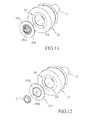
- the first embodiment of a lamp 2 includes a base 21, a light emitting module 22 mounted to the base 21, a lens member 23, a securing unit 24, and a decorating unit 25.
- the base 21 has a connecting surface 211 that faces the light emitting module 22 and that has an engaging portion 212 engaging the lens member 23.
- the light emitting module 22 includes a printed circuit board (PCB) 221 connected to the connecting surface 211, and a plurality of LEDs 222 mounted on the PCB 221 (see Fig. 10 ).
- PCB printed circuit board
- the lens member 23 has a light input surface 231 engaged with the engaging portion 212 of the connecting surface 211 of the base 21, a light output surface 232 disposed in front of and spaced apart from the light input surface 231 along an axis, and a through hole 2300 extending through the light input surface 231 and the light output surface 232.
- light emitted from the light emitting module 22 enters the lens member 23 through the light input surface 231 and exits the lens member 23 through the light output surface 232.
- the light output surface 232 is larger than the light input surface 231.
- the securing unit 24 has a securing portion 241 passing through the through hole 2300 of the lens member 23 and connected fixedly to the base 21 so that the lens member 23 is located between the securing unit 24 and the base 21, a disk-shaped abutment portion 242 abutting against a front end of the lens member 23 and connected to the securing portion 241, and a coupling portion 243 arranged on the abutment portion 242.
- the coupling portion 243 extends forwardly from the center of the abutment portion 242.
- the lens member 23 and the securing unit 24 are provided respectively with first and second engaging components 2301, 2401, and are connected to each other through engagement between the first and second engaging components 2301, 2401.
- the light output surface 232 of the lens member 23 has a stepped receiving portion 233 formed as a recess for receiving a peripheral part of the abutment portion 242 of the securing unit 24.
- the decorating unit 25 is disposed within the light output surface 232 of the lens member 23 for decorating the lamp 2 or optically disposed for changing at least one of a wavelength, an output angle and a light field and so forth of the light passing through the lens member 23.
- the decorating unit 25 has a first decorating member 251, which has a first connecting section 2511 that is detachably connected to the coupling portion 243 of the securing unit 24, and a first decorating section 2512 that is connected to the first connecting section 2511 at an end opposite to the coupling portion 243 of the securing unit 24, and that does not cover the light output surface 232 of the lens member 23 such that the first decorating section 2512 is simply for decorating the lamp.
- a first decorating member 251 which has a first connecting section 2511 that is detachably connected to the coupling portion 243 of the securing unit 24, and a first decorating section 2512 that is connected to the first connecting section 2511 at an end opposite to the coupling portion 243 of the securing unit 24, and that does not cover the light output
- the coupling portion 243 of the securing unit 24 in this embodiment has an annular wall surrounding the axis, defining a securing space therein, and formed with a plurality of angularly-spaced apart notches that extend parallel to the axis and an annular securing groove 2431 that surrounds the axis at the inner side of the coupling portion 243.
- the first connecting section 2511 of the decorating unit 25 in this embodiment has a block inserted into the securing space and formed with an annular external protrusion 2510 that engages the annular securing groove 2431.
- the annular wall of the coupling portion 243 due to the presence of the notches, is radially and outwardly deformed by the annular external protrusion 2510 when the annular external protrusion 2510 is moved along the axis until the annular external protrusion 2510 is slipped into the annular securing groove 2431.
- the method of connecting the securing unit and the decorating unit is not limited to the disclosure herein.
- the decorating unit 25 has a second decorating member 252, which can be interchanged with the first decorating member 251 according to the needs of different occasions.
- the second decorating member 252 has a second connecting section 2521 that is detachably connected to the coupling portion 243 of the securing unit 24 in the same manner as the coupling of the first connecting section 2511 of the first decorating member 251 to the coupling portion 243 of the securing unit 24, and a second decorating section 2522 that is connected to the second connecting section 2521 at an end opposite to the coupling portion 243 of the securing unit 24.
- the second decorating section 2522 is larger in area than the first decorating section 2512 of the first decorating member 251, thereby covering the light output surface 232 of the lens member 23; namely, the decorating unit 25 is optically disposed to the lens member 23 so that the characteristics of the light emitted by the light output surface 232 is changeable by virtue thereof.
- the second decorating section 2522 may be configured as a color filter for changing the light color or have an outer surface formed with a plurality of microstructures (see Fig. 8 ) for changing the light field and so forth of the light passing through the lens member 23.
- the microstructures may be configured as dots or rough structures, wherein they can be used to diffuse or focus the light emitted from the light output surface 232; or configured as prisms or elongated type structures such as V-cut structures or R-cut structures, wherein they can be used to bring on uniform distribution of the light field of the light emitted from the light output surface 232.
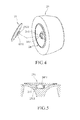
- the second embodiment of the lamp 2 according to the present invention is similar to the first embodiment, except for the configurations of the securing unit 24 and the decorating unit 25.
- the securing unit 24 includes a securing tube 244 passing through the through hole 2300 of the lens member 23 and connected fixedly to the base 21, and an annular abutment portion 245 abutting against the front end of the lens member 23, connected to the securing tube 244 at an end opposite to the base 21 and having the decorating unit 25 detachably connected thereto.
- the abutment portion 245 is received in the receiving portion 233 of the lens member 23.
- the decorating unit 25 in this embodiment further can be replaced by a third decorating member 253, which includes a third connecting section 2531 that is detachably connected to the annular abutment portion 245, and a ring-shaped third decorating section 2532 that is connected to the third connecting section 2531 at an end opposite to the annular abutment portion 245, and that covers the light output surface 232 of the lens member 23.
- the third connecting section 2531 is tubular and slightly smaller in diameter than the securing tube 244, so that it can insert into the securing tube 244 and be secured onto an inner surface of the securing tube 244.
- the abovementioned configurations increase heat-dissipating efficiency of the lamp 2 by allowing air from the external environment to pass through the securing unit 24 and the decorating unit 25.
- the third decorating section 2532 may also be configured as a color filter or have an outer surface formed with a plurality of microstructures for changing the wavelength or angle or light field of the light passing through the lens member 23.
- the decorating unit 25 further can be replaced by a fourth decorating member 254 having a fourth decorating section 2541 that is detachably connected to a front end of the lens member 23, and an auxiliary section 2542 that is connected to and surrounded by the fourth decorating section 2541.
- the auxiliary section 2542 can be designed to have different decorating patterns and formed with a plurality of air holes to allow passage of air therethrough.
- the decorating unit 25 can further be replaced by a fifth decorating member 255 having a fifth decorating section 2551 that is detachably connected to a front end of the lens member 23, and an auxiliary section 2552 that is connected to and surrounded by the fifth decorating section 2551.
- the lamp 2 herein further comprises an ornament 3 connected detachably to the auxiliary section 2552.
- the decoration style may be multiform by changing the design of the ornament 3.
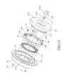
- the third embodiment of the lamp 2 according to the present invention is similar to the first and second embodiments, except for the structures and configurations of the base 21, the securing unit 24 and the decorating unit 25.
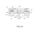
- the securing unit 24 is ring-shaped, is disposed in the base 21 and interposed between the PCB 221 and the lens member 23, and has two L-shaped grooves 246 formed on a side facing the lens member 23, and four angularly spaced-apart threaded through holes 247. Two of the through holes 247 are formed in the grooves 246.
- the base 21 of this embodiment includes four screw holes 214.
- Four front screws 26 are provided to be inserted respectively and threadedly through the through holes 247 to engage respectively and threadedly the screw holes 214 so as to firmly fix the securing unit 24 to the base 21.
- the lens member 23 further includes two protrusions 234 (only one is visible) that respectively engage the grooves 246.
- the protrusions 234 of the lens member 23 are first inserted respectively into the grooves 246 of the securing unit 24, and the lens member 23 is rotated relative to the securing unit 24 to be locked to the securing unit 24.
- Each of the protrusions 234 is formed with a lock hole 235.
- Two rear screws 27 are provided to extend through the base 21 and the securing unit 24 and engage respectively with the lock holes 235 so as to prevent rotation of the lens member 23 relative to the base unit 21. Particularly, as illustrated by Fig.
- the lens member 23 is moved toward the securing unit 24 until the protrusions 234 respectively enter the grooves 246, and is then rotated relative to the securing unit 24 to respectively enter spaces 248 (only one is shown) which are respectively next to the grooves 246 and which extend between the securing unit 24 and the base 21 to finish the assembly of the lens member 23 and the securing unit 24.
- the decorating unit 25 has a sixth decorating member 256 having a sixth decorating section 2562 extending through the lens member 23 and the securing unit 24, and a sixth connecting section 2561 connected detachably to the base 21.
- the decorating unit 25 may be received in a threaded hole 213 defined by the connecting surface 211 of the base 21 by threaded engagement between the sixth connecting section 2561 and the threaded hole 213 (see Fig. 13 ), or the sixth connecting section 2561 may be configured to be connected detachably to the base 21 by being hooked on the connecting surface 211 of base 21.
- the sixth decorating section 2562 does not cover the light output surface 232.
- the first to sixth decorating members 251, 252, 253, 254, 255, 256 can be interchanged according to practical requirements.
- the lamp 2 not only allows a user to detach and replace, for example, the first, fourth, fifth, and sixth decorating members 251, 254, 255, 256 to suit their decorative needs, but also lets the user detach and replace, for example, the second and third decorating members 252, 253, which further provides a wide variety of customization options in terms of color, light field, etc. to achieve the user's desired lighting effects.
Applications Claiming Priority (1)
| Application Number | Priority Date | Filing Date | Title |
|---|---|---|---|
| TW103111975 | 2014-03-31 |
Publications (2)
| Publication Number | Publication Date |
|---|---|
| EP2927561A1 true EP2927561A1 (fr) | 2015-10-07 |
| EP2927561B1 EP2927561B1 (fr) | 2017-02-22 |
Family
ID=51187640
Family Applications (1)
| Application Number | Title | Priority Date | Filing Date |
|---|---|---|---|
| EP15161610.9A Active EP2927561B1 (fr) | 2014-03-31 | 2015-03-30 | Lampe |
Country Status (4)
| Country | Link |
|---|---|
| US (1) | US9719659B2 (fr) |
| EP (1) | EP2927561B1 (fr) |
| CN (2) | CN103939857B (fr) |
| TW (2) | TWI628393B (fr) |
Cited By (1)
| Publication number | Priority date | Publication date | Assignee | Title |
|---|---|---|---|---|
| EP3263981A1 (fr) * | 2016-06-28 | 2018-01-03 | OSRAM GmbH | Procédé de fabrication d'éléments optiques pour dispositifs d'éclairage et élément optique correspondant |
Families Citing this family (8)
| Publication number | Priority date | Publication date | Assignee | Title |
|---|---|---|---|---|
| US20180003374A1 (en) * | 2015-01-06 | 2018-01-04 | Erin Bulcao | Motion Activated Illumination Device for Use with a Toilet |
| US10288238B2 (en) * | 2015-06-23 | 2019-05-14 | Axis Lighting Inc. | Supporting accessories for ceiling structures |
| USD859719S1 (en) | 2015-06-23 | 2019-09-10 | Axis Lighting Inc. | Luminaire |
| CA3038002A1 (fr) * | 2018-03-28 | 2019-09-28 | Abl Ip Holding Llc | Luminaire haut-parleur equipe d'un tuyau d'eclairage |
| CN109519891A (zh) * | 2018-12-25 | 2019-03-26 | 赛尔富电子有限公司 | 一种灯具 |
| CN210979554U (zh) * | 2019-10-16 | 2020-07-10 | 漳州立达信光电子科技有限公司 | 吸顶灯 |
| AU2021212608B2 (en) * | 2020-01-31 | 2024-03-07 | American Sterilizer Company | Light head with rotating lens assembly and method of operating same |
| EP4105547A4 (fr) * | 2020-10-09 | 2023-05-31 | Radiant Opto-electronics (Suzhou) Co., Ltd. | Lampe |
Citations (8)
| Publication number | Priority date | Publication date | Assignee | Title |
|---|---|---|---|---|
| WO1998055798A2 (fr) * | 1997-06-04 | 1998-12-10 | Simon Jerome H | Lentille ondulee de refraction et de reflexion, utile pour mettre en forme de la lumiere |
| US20060007692A1 (en) * | 2004-07-07 | 2006-01-12 | Hsien Chen S | Lamp assembly |
| US20110309735A1 (en) * | 2010-06-18 | 2011-12-22 | Parker Jeffery R | Light bulb using solid-state light sources |
| WO2013013514A1 (fr) * | 2011-07-28 | 2013-01-31 | 厦门立明光电有限公司 | Lampe d'éclairage à diodes électroluminescentes |
| WO2013023022A2 (fr) * | 2011-08-09 | 2013-02-14 | Rambus Inc. | Ampoule lumineuse dotée de caractéristiques thermiques |
| WO2013190979A1 (fr) * | 2012-06-19 | 2013-12-27 | 株式会社 東芝 | Dispositif d'éclairage |
| EP2679896A1 (fr) * | 2012-06-29 | 2014-01-01 | Kabushiki Kaisha Toshiba | Dispositif d'éclairage |
| WO2014138163A1 (fr) * | 2013-03-05 | 2014-09-12 | Terralux, Inc. | Ampoule à diode électroluminescente générant un éclairage direct et décoratif |
Family Cites Families (24)
| Publication number | Priority date | Publication date | Assignee | Title |
|---|---|---|---|---|
| TW454851U (en) * | 2000-09-18 | 2001-09-11 | Shen Wei Hung | Decorating connector structure |
| US7222988B2 (en) * | 2004-09-21 | 2007-05-29 | Gober David A | Display device for illuminating optical storage disks for visual display and method of using the same |
| US20100073960A1 (en) * | 2008-09-22 | 2010-03-25 | Yi-Hsueh Yang | Color pattern forming device |
| US7934845B2 (en) * | 2008-10-03 | 2011-05-03 | Chin-Sheng Yang | Candle like lighting device |
| CN201289044Y (zh) | 2008-10-28 | 2009-08-12 | 深圳市浪尖工业产品造型设计有限公司 | Led发光装置 |
| CN101839437B (zh) | 2009-03-21 | 2013-06-05 | 富准精密工业(深圳)有限公司 | 装饰灯具 |
| JP2010250966A (ja) | 2009-04-10 | 2010-11-04 | Toshiba Lighting & Technology Corp | 照明器具 |
| US9004737B2 (en) | 2009-05-12 | 2015-04-14 | Global Lighting Technologies Inc. | Illumination apparatus |
| CN201696900U (zh) * | 2010-01-08 | 2011-01-05 | 大连九久光电制造有限公司 | Led筒灯 |
| US8201983B2 (en) * | 2010-06-01 | 2012-06-19 | Young Lighting Technology Inc. | Illuminating device |
| CN102444790B (zh) * | 2010-09-30 | 2014-11-19 | 光宝电子(广州)有限公司 | 灯具 |
| TWM404310U (en) | 2010-12-03 | 2011-05-21 | Wing Lian Lighting Co Ltd | Art lamps having light transmissive decoration plate structure |
| US8487518B2 (en) * | 2010-12-06 | 2013-07-16 | 3M Innovative Properties Company | Solid state light with optical guide and integrated thermal guide |
| CN102052623A (zh) | 2011-01-30 | 2011-05-11 | 陈晓锋 | 一种新型装饰照明灯 |
| TW201339502A (zh) * | 2012-03-23 | 2013-10-01 | Enlight Corp | 燈具結構 |
| CN202613256U (zh) | 2012-05-11 | 2012-12-19 | 云南鼎坤科技有限公司 | 一种超薄结构小功率贴片led筒灯 |
| US9028129B2 (en) * | 2012-10-01 | 2015-05-12 | Rambus Delaware Llc | LED lamp and led lighting assembly |
| CN203190245U (zh) * | 2012-11-14 | 2013-09-11 | 许少群 | 多个发光体组合的灯具结构 |
| CN203036387U (zh) | 2012-11-30 | 2013-07-03 | 深圳市奥拓光电科技有限公司 | 一种led侧发光平板灯 |
| CN203202768U (zh) | 2013-04-23 | 2013-09-18 | 苗光夫 | 新型led吊灯 |
| CN203322987U (zh) * | 2013-05-23 | 2013-12-04 | 陈小清 | 一种分离式led光源装饰灯结构 |
| CN103335277A (zh) * | 2013-06-05 | 2013-10-02 | 江苏华安高技术安防产业有限公司 | 具有空腔结构的导光灯及其制造方法 |
| CN103574516B (zh) * | 2013-07-22 | 2016-02-03 | 瑞仪光电股份有限公司 | 可控制光束角的导光元件及灯具 |
| TWM481330U (zh) | 2013-11-20 | 2014-07-01 | Jin-Sheng Yang | 光纖燈飾 |
-
2014
- 2014-05-06 CN CN201410189405.4A patent/CN103939857B/zh active Active
- 2014-05-06 CN CN201710144000.2A patent/CN107091462A/zh not_active Withdrawn
-
2015
- 2015-01-09 TW TW106100639A patent/TWI628393B/zh active
- 2015-03-25 US US14/668,168 patent/US9719659B2/en active Active
- 2015-03-27 TW TW104110024A patent/TW201537086A/zh unknown
- 2015-03-30 EP EP15161610.9A patent/EP2927561B1/fr active Active
Patent Citations (9)
| Publication number | Priority date | Publication date | Assignee | Title |
|---|---|---|---|---|
| WO1998055798A2 (fr) * | 1997-06-04 | 1998-12-10 | Simon Jerome H | Lentille ondulee de refraction et de reflexion, utile pour mettre en forme de la lumiere |
| US20060007692A1 (en) * | 2004-07-07 | 2006-01-12 | Hsien Chen S | Lamp assembly |
| US20110309735A1 (en) * | 2010-06-18 | 2011-12-22 | Parker Jeffery R | Light bulb using solid-state light sources |
| WO2013013514A1 (fr) * | 2011-07-28 | 2013-01-31 | 厦门立明光电有限公司 | Lampe d'éclairage à diodes électroluminescentes |
| EP2738457A1 (fr) * | 2011-07-28 | 2014-06-04 | Leeleds Lighting (Xiamen) Co., Ltd. | Lampe d'éclairage à diodes électroluminescentes |
| WO2013023022A2 (fr) * | 2011-08-09 | 2013-02-14 | Rambus Inc. | Ampoule lumineuse dotée de caractéristiques thermiques |
| WO2013190979A1 (fr) * | 2012-06-19 | 2013-12-27 | 株式会社 東芝 | Dispositif d'éclairage |
| EP2679896A1 (fr) * | 2012-06-29 | 2014-01-01 | Kabushiki Kaisha Toshiba | Dispositif d'éclairage |
| WO2014138163A1 (fr) * | 2013-03-05 | 2014-09-12 | Terralux, Inc. | Ampoule à diode électroluminescente générant un éclairage direct et décoratif |
Cited By (1)
| Publication number | Priority date | Publication date | Assignee | Title |
|---|---|---|---|---|
| EP3263981A1 (fr) * | 2016-06-28 | 2018-01-03 | OSRAM GmbH | Procédé de fabrication d'éléments optiques pour dispositifs d'éclairage et élément optique correspondant |
Also Published As
| Publication number | Publication date |
|---|---|
| TW201537086A (zh) | 2015-10-01 |
| TWI563204B (fr) | 2016-12-21 |
| US20150276176A1 (en) | 2015-10-01 |
| CN103939857A (zh) | 2014-07-23 |
| CN107091462A (zh) | 2017-08-25 |
| CN103939857B (zh) | 2017-04-12 |
| US9719659B2 (en) | 2017-08-01 |
| TW201716723A (zh) | 2017-05-16 |
| EP2927561B1 (fr) | 2017-02-22 |
| TWI628393B (zh) | 2018-07-01 |
Similar Documents
| Publication | Publication Date | Title |
|---|---|---|
| EP2927561B1 (fr) | Lampe | |
| US10386023B2 (en) | LED light fixture and assembly method therefor | |
| EP2943821B1 (fr) | Lentille avec une dense distribution de facettes convexes sur ses faces d'entrée et de sortie | |
| US8573816B2 (en) | Composite lens with diffusion | |
| EP3149393B1 (fr) | Luminaire intégré à del décoratif | |
| US20160312977A1 (en) | Total internal reflection lens with step-shaped front surface and central convex region | |
| EP3832197B1 (fr) | Structure d'abat-jour et lampe | |
| US9033563B1 (en) | Vehicle headlight assembly | |
| JP2015018774A (ja) | 照明装置 | |
| US20170136942A1 (en) | Tail light device for an automobile | |
| EP3631287B1 (fr) | Luminaire | |
| JP2019053879A (ja) | 光源モジュール及び照明装置 | |
| CN205079081U (zh) | 一种灯具 | |
| CN210688078U (zh) | 可调焦调色温地插灯 | |
| US10288258B1 (en) | Lighting module | |
| GB2504686A (en) | A downlighter or uplighter light source | |
| TWM519219U (zh) | 光束控制元件 | |
| CN102759034A (zh) | 发光二极管灯管 |
Legal Events
| Date | Code | Title | Description |
|---|---|---|---|
| PUAI | Public reference made under article 153(3) epc to a published international application that has entered the european phase |
Free format text: ORIGINAL CODE: 0009012 |
|
| AK | Designated contracting states |
Kind code of ref document: A1 Designated state(s): AL AT BE BG CH CY CZ DE DK EE ES FI FR GB GR HR HU IE IS IT LI LT LU LV MC MK MT NL NO PL PT RO RS SE SI SK SM TR |
|
| AX | Request for extension of the european patent |
Extension state: BA ME |
|
| 17P | Request for examination filed |
Effective date: 20160407 |
|
| RBV | Designated contracting states (corrected) |
Designated state(s): AL AT BE BG CH CY CZ DE DK EE ES FI FR GB GR HR HU IE IS IT LI LT LU LV MC MK MT NL NO PL PT RO RS SE SI SK SM TR |
|
| REG | Reference to a national code |
Ref country code: DE Ref legal event code: R079 Ref document number: 602015001529 Country of ref document: DE Free format text: PREVIOUS MAIN CLASS: F21K0099000000 Ipc: F21K0009600000 |
|
| RIC1 | Information provided on ipc code assigned before grant |
Ipc: F21Y 103/33 20160101ALN20160830BHEP Ipc: F21K 9/60 20160101AFI20160830BHEP Ipc: F21V 17/00 20060101ALI20160830BHEP Ipc: F21V 5/04 20060101ALI20160830BHEP Ipc: F21Y 115/10 20160101ALN20160830BHEP |
|
| RIC1 | Information provided on ipc code assigned before grant |
Ipc: F21V 17/00 20060101ALI20160902BHEP Ipc: F21V 5/04 20060101ALI20160902BHEP Ipc: F21Y 103/33 20160101ALN20160902BHEP Ipc: F21K 9/60 20160101AFI20160902BHEP Ipc: F21Y 115/10 20160101ALN20160902BHEP |
|
| GRAP | Despatch of communication of intention to grant a patent |
Free format text: ORIGINAL CODE: EPIDOSNIGR1 |
|
| RIC1 | Information provided on ipc code assigned before grant |
Ipc: F21V 5/04 20060101ALI20160926BHEP Ipc: F21Y 103/33 20160101ALN20160926BHEP Ipc: F21V 17/00 20060101ALI20160926BHEP Ipc: F21K 9/60 20160101AFI20160926BHEP Ipc: F21Y 115/10 20160101ALN20160926BHEP |
|
| INTG | Intention to grant announced |
Effective date: 20161014 |
|
| RIC1 | Information provided on ipc code assigned before grant |
Ipc: F21V 17/00 20060101ALI20161004BHEP Ipc: F21V 5/04 20060101ALI20161004BHEP Ipc: F21Y 115/10 20160101ALN20161004BHEP Ipc: F21Y 103/33 20160101ALN20161004BHEP Ipc: F21K 9/60 20160101AFI20161004BHEP |
|
| STAA | Information on the status of an ep patent application or granted ep patent |
Free format text: STATUS: GRANT OF PATENT IS INTENDED |
|
| GRAS | Grant fee paid |
Free format text: ORIGINAL CODE: EPIDOSNIGR3 |
|
| GRAA | (expected) grant |
Free format text: ORIGINAL CODE: 0009210 |
|
| STAA | Information on the status of an ep patent application or granted ep patent |
Free format text: STATUS: THE PATENT HAS BEEN GRANTED |
|
| AK | Designated contracting states |
Kind code of ref document: B1 Designated state(s): AL AT BE BG CH CY CZ DE DK EE ES FI FR GB GR HR HU IE IS IT LI LT LU LV MC MK MT NL NO PL PT RO RS SE SI SK SM TR |
|
| REG | Reference to a national code |
Ref country code: GB Ref legal event code: FG4D |
|
| REG | Reference to a national code |
Ref country code: CH Ref legal event code: EP |
|
| REG | Reference to a national code |
Ref country code: FR Ref legal event code: PLFP Year of fee payment: 3 |
|
| REG | Reference to a national code |
Ref country code: AT Ref legal event code: REF Ref document number: 869545 Country of ref document: AT Kind code of ref document: T Effective date: 20170315 |
|
| REG | Reference to a national code |
Ref country code: IE Ref legal event code: FG4D |
|
| REG | Reference to a national code |
Ref country code: DE Ref legal event code: R096 Ref document number: 602015001529 Country of ref document: DE |
|
| REG | Reference to a national code |
Ref country code: NL Ref legal event code: FP |
|
| REG | Reference to a national code |
Ref country code: LT Ref legal event code: MG4D |
|
| REG | Reference to a national code |
Ref country code: AT Ref legal event code: MK05 Ref document number: 869545 Country of ref document: AT Kind code of ref document: T Effective date: 20170222 |
|
| PG25 | Lapsed in a contracting state [announced via postgrant information from national office to epo] |
Ref country code: LT Free format text: LAPSE BECAUSE OF FAILURE TO SUBMIT A TRANSLATION OF THE DESCRIPTION OR TO PAY THE FEE WITHIN THE PRESCRIBED TIME-LIMIT Effective date: 20170222 Ref country code: GR Free format text: LAPSE BECAUSE OF FAILURE TO SUBMIT A TRANSLATION OF THE DESCRIPTION OR TO PAY THE FEE WITHIN THE PRESCRIBED TIME-LIMIT Effective date: 20170523 Ref country code: HR Free format text: LAPSE BECAUSE OF FAILURE TO SUBMIT A TRANSLATION OF THE DESCRIPTION OR TO PAY THE FEE WITHIN THE PRESCRIBED TIME-LIMIT Effective date: 20170222 Ref country code: NO Free format text: LAPSE BECAUSE OF FAILURE TO SUBMIT A TRANSLATION OF THE DESCRIPTION OR TO PAY THE FEE WITHIN THE PRESCRIBED TIME-LIMIT Effective date: 20170522 Ref country code: FI Free format text: LAPSE BECAUSE OF FAILURE TO SUBMIT A TRANSLATION OF THE DESCRIPTION OR TO PAY THE FEE WITHIN THE PRESCRIBED TIME-LIMIT Effective date: 20170222 |
|
| PG25 | Lapsed in a contracting state [announced via postgrant information from national office to epo] |
Ref country code: AT Free format text: LAPSE BECAUSE OF FAILURE TO SUBMIT A TRANSLATION OF THE DESCRIPTION OR TO PAY THE FEE WITHIN THE PRESCRIBED TIME-LIMIT Effective date: 20170222 Ref country code: PT Free format text: LAPSE BECAUSE OF FAILURE TO SUBMIT A TRANSLATION OF THE DESCRIPTION OR TO PAY THE FEE WITHIN THE PRESCRIBED TIME-LIMIT Effective date: 20170622 Ref country code: SE Free format text: LAPSE BECAUSE OF FAILURE TO SUBMIT A TRANSLATION OF THE DESCRIPTION OR TO PAY THE FEE WITHIN THE PRESCRIBED TIME-LIMIT Effective date: 20170222 Ref country code: BG Free format text: LAPSE BECAUSE OF FAILURE TO SUBMIT A TRANSLATION OF THE DESCRIPTION OR TO PAY THE FEE WITHIN THE PRESCRIBED TIME-LIMIT Effective date: 20170522 Ref country code: RS Free format text: LAPSE BECAUSE OF FAILURE TO SUBMIT A TRANSLATION OF THE DESCRIPTION OR TO PAY THE FEE WITHIN THE PRESCRIBED TIME-LIMIT Effective date: 20170222 Ref country code: ES Free format text: LAPSE BECAUSE OF FAILURE TO SUBMIT A TRANSLATION OF THE DESCRIPTION OR TO PAY THE FEE WITHIN THE PRESCRIBED TIME-LIMIT Effective date: 20170222 Ref country code: LV Free format text: LAPSE BECAUSE OF FAILURE TO SUBMIT A TRANSLATION OF THE DESCRIPTION OR TO PAY THE FEE WITHIN THE PRESCRIBED TIME-LIMIT Effective date: 20170222 |
|
| PG25 | Lapsed in a contracting state [announced via postgrant information from national office to epo] |
Ref country code: CZ Free format text: LAPSE BECAUSE OF FAILURE TO SUBMIT A TRANSLATION OF THE DESCRIPTION OR TO PAY THE FEE WITHIN THE PRESCRIBED TIME-LIMIT Effective date: 20170222 Ref country code: SK Free format text: LAPSE BECAUSE OF FAILURE TO SUBMIT A TRANSLATION OF THE DESCRIPTION OR TO PAY THE FEE WITHIN THE PRESCRIBED TIME-LIMIT Effective date: 20170222 Ref country code: IT Free format text: LAPSE BECAUSE OF FAILURE TO SUBMIT A TRANSLATION OF THE DESCRIPTION OR TO PAY THE FEE WITHIN THE PRESCRIBED TIME-LIMIT Effective date: 20170222 Ref country code: EE Free format text: LAPSE BECAUSE OF FAILURE TO SUBMIT A TRANSLATION OF THE DESCRIPTION OR TO PAY THE FEE WITHIN THE PRESCRIBED TIME-LIMIT Effective date: 20170222 Ref country code: RO Free format text: LAPSE BECAUSE OF FAILURE TO SUBMIT A TRANSLATION OF THE DESCRIPTION OR TO PAY THE FEE WITHIN THE PRESCRIBED TIME-LIMIT Effective date: 20170222 |
|
| REG | Reference to a national code |
Ref country code: DE Ref legal event code: R097 Ref document number: 602015001529 Country of ref document: DE |
|
| PG25 | Lapsed in a contracting state [announced via postgrant information from national office to epo] |
Ref country code: DK Free format text: LAPSE BECAUSE OF FAILURE TO SUBMIT A TRANSLATION OF THE DESCRIPTION OR TO PAY THE FEE WITHIN THE PRESCRIBED TIME-LIMIT Effective date: 20170222 Ref country code: SM Free format text: LAPSE BECAUSE OF FAILURE TO SUBMIT A TRANSLATION OF THE DESCRIPTION OR TO PAY THE FEE WITHIN THE PRESCRIBED TIME-LIMIT Effective date: 20170222 Ref country code: PL Free format text: LAPSE BECAUSE OF FAILURE TO SUBMIT A TRANSLATION OF THE DESCRIPTION OR TO PAY THE FEE WITHIN THE PRESCRIBED TIME-LIMIT Effective date: 20170222 Ref country code: MC Free format text: LAPSE BECAUSE OF FAILURE TO SUBMIT A TRANSLATION OF THE DESCRIPTION OR TO PAY THE FEE WITHIN THE PRESCRIBED TIME-LIMIT Effective date: 20170222 |
|
| REG | Reference to a national code |
Ref country code: FR Ref legal event code: PLFP Year of fee payment: 4 |
|
| REG | Reference to a national code |
Ref country code: IE Ref legal event code: MM4A |
|
| PLBE | No opposition filed within time limit |
Free format text: ORIGINAL CODE: 0009261 |
|
| STAA | Information on the status of an ep patent application or granted ep patent |
Free format text: STATUS: NO OPPOSITION FILED WITHIN TIME LIMIT |
|
| 26N | No opposition filed |
Effective date: 20171123 |
|
| PG25 | Lapsed in a contracting state [announced via postgrant information from national office to epo] |
Ref country code: LU Free format text: LAPSE BECAUSE OF NON-PAYMENT OF DUE FEES Effective date: 20170330 |
|
| PG25 | Lapsed in a contracting state [announced via postgrant information from national office to epo] |
Ref country code: IE Free format text: LAPSE BECAUSE OF NON-PAYMENT OF DUE FEES Effective date: 20170330 Ref country code: SI Free format text: LAPSE BECAUSE OF FAILURE TO SUBMIT A TRANSLATION OF THE DESCRIPTION OR TO PAY THE FEE WITHIN THE PRESCRIBED TIME-LIMIT Effective date: 20170222 |
|
| REG | Reference to a national code |
Ref country code: BE Ref legal event code: MM Effective date: 20170331 |
|
| PG25 | Lapsed in a contracting state [announced via postgrant information from national office to epo] |
Ref country code: BE Free format text: LAPSE BECAUSE OF NON-PAYMENT OF DUE FEES Effective date: 20170331 |
|
| PG25 | Lapsed in a contracting state [announced via postgrant information from national office to epo] |
Ref country code: MT Free format text: LAPSE BECAUSE OF NON-PAYMENT OF DUE FEES Effective date: 20170330 |
|
| REG | Reference to a national code |
Ref country code: CH Ref legal event code: PL |
|
| PG25 | Lapsed in a contracting state [announced via postgrant information from national office to epo] |
Ref country code: LI Free format text: LAPSE BECAUSE OF NON-PAYMENT OF DUE FEES Effective date: 20180331 Ref country code: CH Free format text: LAPSE BECAUSE OF NON-PAYMENT OF DUE FEES Effective date: 20180331 |
|
| PG25 | Lapsed in a contracting state [announced via postgrant information from national office to epo] |
Ref country code: HU Free format text: LAPSE BECAUSE OF FAILURE TO SUBMIT A TRANSLATION OF THE DESCRIPTION OR TO PAY THE FEE WITHIN THE PRESCRIBED TIME-LIMIT; INVALID AB INITIO Effective date: 20150330 |
|
| PG25 | Lapsed in a contracting state [announced via postgrant information from national office to epo] |
Ref country code: CY Free format text: LAPSE BECAUSE OF FAILURE TO SUBMIT A TRANSLATION OF THE DESCRIPTION OR TO PAY THE FEE WITHIN THE PRESCRIBED TIME-LIMIT Effective date: 20170222 |
|
| PG25 | Lapsed in a contracting state [announced via postgrant information from national office to epo] |
Ref country code: MK Free format text: LAPSE BECAUSE OF FAILURE TO SUBMIT A TRANSLATION OF THE DESCRIPTION OR TO PAY THE FEE WITHIN THE PRESCRIBED TIME-LIMIT Effective date: 20170222 |
|
| PG25 | Lapsed in a contracting state [announced via postgrant information from national office to epo] |
Ref country code: TR Free format text: LAPSE BECAUSE OF FAILURE TO SUBMIT A TRANSLATION OF THE DESCRIPTION OR TO PAY THE FEE WITHIN THE PRESCRIBED TIME-LIMIT Effective date: 20170222 |
|
| PG25 | Lapsed in a contracting state [announced via postgrant information from national office to epo] |
Ref country code: AL Free format text: LAPSE BECAUSE OF FAILURE TO SUBMIT A TRANSLATION OF THE DESCRIPTION OR TO PAY THE FEE WITHIN THE PRESCRIBED TIME-LIMIT Effective date: 20170222 Ref country code: IS Free format text: LAPSE BECAUSE OF FAILURE TO SUBMIT A TRANSLATION OF THE DESCRIPTION OR TO PAY THE FEE WITHIN THE PRESCRIBED TIME-LIMIT Effective date: 20170622 |
|
| PGFP | Annual fee paid to national office [announced via postgrant information from national office to epo] |
Ref country code: NL Payment date: 20231109 Year of fee payment: 10 |
|
| PGFP | Annual fee paid to national office [announced via postgrant information from national office to epo] |
Ref country code: FR Payment date: 20231110 Year of fee payment: 10 |
|
| PGFP | Annual fee paid to national office [announced via postgrant information from national office to epo] |
Ref country code: DE Payment date: 20231109 Year of fee payment: 10 Ref country code: GB Payment date: 20240103 Year of fee payment: 10 |