EP2927445A1 - Exhaust purification system for internal combustion engine - Google Patents
Exhaust purification system for internal combustion engine Download PDFInfo
- Publication number
- EP2927445A1 EP2927445A1 EP12889659.4A EP12889659A EP2927445A1 EP 2927445 A1 EP2927445 A1 EP 2927445A1 EP 12889659 A EP12889659 A EP 12889659A EP 2927445 A1 EP2927445 A1 EP 2927445A1
- Authority
- EP
- European Patent Office
- Prior art keywords
- catalyst
- temperature
- exhaust gas
- filter
- execution
- Prior art date
- Legal status (The legal status is an assumption and is not a legal conclusion. Google has not performed a legal analysis and makes no representation as to the accuracy of the status listed.)
- Granted
Links
Images


Classifications
-
- F—MECHANICAL ENGINEERING; LIGHTING; HEATING; WEAPONS; BLASTING
- F01—MACHINES OR ENGINES IN GENERAL; ENGINE PLANTS IN GENERAL; STEAM ENGINES
- F01N—GAS-FLOW SILENCERS OR EXHAUST APPARATUS FOR MACHINES OR ENGINES IN GENERAL; GAS-FLOW SILENCERS OR EXHAUST APPARATUS FOR INTERNAL COMBUSTION ENGINES
- F01N9/00—Electrical control of exhaust gas treating apparatus
-
- F—MECHANICAL ENGINEERING; LIGHTING; HEATING; WEAPONS; BLASTING
- F01—MACHINES OR ENGINES IN GENERAL; ENGINE PLANTS IN GENERAL; STEAM ENGINES
- F01N—GAS-FLOW SILENCERS OR EXHAUST APPARATUS FOR MACHINES OR ENGINES IN GENERAL; GAS-FLOW SILENCERS OR EXHAUST APPARATUS FOR INTERNAL COMBUSTION ENGINES
- F01N11/00—Monitoring or diagnostic devices for exhaust-gas treatment apparatus, e.g. for catalytic activity
- F01N11/002—Monitoring or diagnostic devices for exhaust-gas treatment apparatus, e.g. for catalytic activity the diagnostic devices measuring or estimating temperature or pressure in, or downstream of the exhaust apparatus
-
- F—MECHANICAL ENGINEERING; LIGHTING; HEATING; WEAPONS; BLASTING
- F01—MACHINES OR ENGINES IN GENERAL; ENGINE PLANTS IN GENERAL; STEAM ENGINES
- F01N—GAS-FLOW SILENCERS OR EXHAUST APPARATUS FOR MACHINES OR ENGINES IN GENERAL; GAS-FLOW SILENCERS OR EXHAUST APPARATUS FOR INTERNAL COMBUSTION ENGINES
- F01N13/00—Exhaust or silencing apparatus characterised by constructional features ; Exhaust or silencing apparatus, or parts thereof, having pertinent characteristics not provided for in, or of interest apart from, groups F01N1/00 - F01N5/00, F01N9/00, F01N11/00
- F01N13/009—Exhaust or silencing apparatus characterised by constructional features ; Exhaust or silencing apparatus, or parts thereof, having pertinent characteristics not provided for in, or of interest apart from, groups F01N1/00 - F01N5/00, F01N9/00, F01N11/00 having two or more separate purifying devices arranged in series
-
- F—MECHANICAL ENGINEERING; LIGHTING; HEATING; WEAPONS; BLASTING
- F01—MACHINES OR ENGINES IN GENERAL; ENGINE PLANTS IN GENERAL; STEAM ENGINES
- F01N—GAS-FLOW SILENCERS OR EXHAUST APPARATUS FOR MACHINES OR ENGINES IN GENERAL; GAS-FLOW SILENCERS OR EXHAUST APPARATUS FOR INTERNAL COMBUSTION ENGINES
- F01N3/00—Exhaust or silencing apparatus having means for purifying, rendering innocuous, or otherwise treating exhaust
- F01N3/02—Exhaust or silencing apparatus having means for purifying, rendering innocuous, or otherwise treating exhaust for cooling, or for removing solid constituents of, exhaust
- F01N3/021—Exhaust or silencing apparatus having means for purifying, rendering innocuous, or otherwise treating exhaust for cooling, or for removing solid constituents of, exhaust by means of filters
- F01N3/023—Exhaust or silencing apparatus having means for purifying, rendering innocuous, or otherwise treating exhaust for cooling, or for removing solid constituents of, exhaust by means of filters using means for regenerating the filters, e.g. by burning trapped particles
- F01N3/025—Exhaust or silencing apparatus having means for purifying, rendering innocuous, or otherwise treating exhaust for cooling, or for removing solid constituents of, exhaust by means of filters using means for regenerating the filters, e.g. by burning trapped particles using fuel burner or by adding fuel to exhaust
- F01N3/0253—Exhaust or silencing apparatus having means for purifying, rendering innocuous, or otherwise treating exhaust for cooling, or for removing solid constituents of, exhaust by means of filters using means for regenerating the filters, e.g. by burning trapped particles using fuel burner or by adding fuel to exhaust adding fuel to exhaust gases
-
- F—MECHANICAL ENGINEERING; LIGHTING; HEATING; WEAPONS; BLASTING
- F01—MACHINES OR ENGINES IN GENERAL; ENGINE PLANTS IN GENERAL; STEAM ENGINES
- F01N—GAS-FLOW SILENCERS OR EXHAUST APPARATUS FOR MACHINES OR ENGINES IN GENERAL; GAS-FLOW SILENCERS OR EXHAUST APPARATUS FOR INTERNAL COMBUSTION ENGINES
- F01N3/00—Exhaust or silencing apparatus having means for purifying, rendering innocuous, or otherwise treating exhaust
- F01N3/02—Exhaust or silencing apparatus having means for purifying, rendering innocuous, or otherwise treating exhaust for cooling, or for removing solid constituents of, exhaust
- F01N3/021—Exhaust or silencing apparatus having means for purifying, rendering innocuous, or otherwise treating exhaust for cooling, or for removing solid constituents of, exhaust by means of filters
- F01N3/033—Exhaust or silencing apparatus having means for purifying, rendering innocuous, or otherwise treating exhaust for cooling, or for removing solid constituents of, exhaust by means of filters in combination with other devices
- F01N3/035—Exhaust or silencing apparatus having means for purifying, rendering innocuous, or otherwise treating exhaust for cooling, or for removing solid constituents of, exhaust by means of filters in combination with other devices with catalytic reactors, e.g. catalysed diesel particulate filters
-
- F—MECHANICAL ENGINEERING; LIGHTING; HEATING; WEAPONS; BLASTING
- F01—MACHINES OR ENGINES IN GENERAL; ENGINE PLANTS IN GENERAL; STEAM ENGINES
- F01N—GAS-FLOW SILENCERS OR EXHAUST APPARATUS FOR MACHINES OR ENGINES IN GENERAL; GAS-FLOW SILENCERS OR EXHAUST APPARATUS FOR INTERNAL COMBUSTION ENGINES
- F01N3/00—Exhaust or silencing apparatus having means for purifying, rendering innocuous, or otherwise treating exhaust
- F01N3/08—Exhaust or silencing apparatus having means for purifying, rendering innocuous, or otherwise treating exhaust for rendering innocuous
- F01N3/10—Exhaust or silencing apparatus having means for purifying, rendering innocuous, or otherwise treating exhaust for rendering innocuous by thermal or catalytic conversion of noxious components of exhaust
- F01N3/103—Oxidation catalysts for HC and CO only
-
- F—MECHANICAL ENGINEERING; LIGHTING; HEATING; WEAPONS; BLASTING
- F01—MACHINES OR ENGINES IN GENERAL; ENGINE PLANTS IN GENERAL; STEAM ENGINES
- F01N—GAS-FLOW SILENCERS OR EXHAUST APPARATUS FOR MACHINES OR ENGINES IN GENERAL; GAS-FLOW SILENCERS OR EXHAUST APPARATUS FOR INTERNAL COMBUSTION ENGINES
- F01N3/00—Exhaust or silencing apparatus having means for purifying, rendering innocuous, or otherwise treating exhaust
- F01N3/08—Exhaust or silencing apparatus having means for purifying, rendering innocuous, or otherwise treating exhaust for rendering innocuous
- F01N3/10—Exhaust or silencing apparatus having means for purifying, rendering innocuous, or otherwise treating exhaust for rendering innocuous by thermal or catalytic conversion of noxious components of exhaust
- F01N3/105—General auxiliary catalysts, e.g. upstream or downstream of the main catalyst
- F01N3/106—Auxiliary oxidation catalysts
-
- F—MECHANICAL ENGINEERING; LIGHTING; HEATING; WEAPONS; BLASTING
- F01—MACHINES OR ENGINES IN GENERAL; ENGINE PLANTS IN GENERAL; STEAM ENGINES
- F01N—GAS-FLOW SILENCERS OR EXHAUST APPARATUS FOR MACHINES OR ENGINES IN GENERAL; GAS-FLOW SILENCERS OR EXHAUST APPARATUS FOR INTERNAL COMBUSTION ENGINES
- F01N3/00—Exhaust or silencing apparatus having means for purifying, rendering innocuous, or otherwise treating exhaust
- F01N3/08—Exhaust or silencing apparatus having means for purifying, rendering innocuous, or otherwise treating exhaust for rendering innocuous
- F01N3/10—Exhaust or silencing apparatus having means for purifying, rendering innocuous, or otherwise treating exhaust for rendering innocuous by thermal or catalytic conversion of noxious components of exhaust
- F01N3/18—Exhaust or silencing apparatus having means for purifying, rendering innocuous, or otherwise treating exhaust for rendering innocuous by thermal or catalytic conversion of noxious components of exhaust characterised by methods of operation; Control
- F01N3/20—Exhaust or silencing apparatus having means for purifying, rendering innocuous, or otherwise treating exhaust for rendering innocuous by thermal or catalytic conversion of noxious components of exhaust characterised by methods of operation; Control specially adapted for catalytic conversion ; Methods of operation or control of catalytic converters
- F01N3/2066—Selective catalytic reduction [SCR]
- F01N3/208—Control of selective catalytic reduction [SCR], e.g. dosing of reducing agent
-
- F—MECHANICAL ENGINEERING; LIGHTING; HEATING; WEAPONS; BLASTING
- F01—MACHINES OR ENGINES IN GENERAL; ENGINE PLANTS IN GENERAL; STEAM ENGINES
- F01N—GAS-FLOW SILENCERS OR EXHAUST APPARATUS FOR MACHINES OR ENGINES IN GENERAL; GAS-FLOW SILENCERS OR EXHAUST APPARATUS FOR INTERNAL COMBUSTION ENGINES
- F01N9/00—Electrical control of exhaust gas treating apparatus
- F01N9/002—Electrical control of exhaust gas treating apparatus of filter regeneration, e.g. detection of clogging
-
- F—MECHANICAL ENGINEERING; LIGHTING; HEATING; WEAPONS; BLASTING
- F02—COMBUSTION ENGINES; HOT-GAS OR COMBUSTION-PRODUCT ENGINE PLANTS
- F02D—CONTROLLING COMBUSTION ENGINES
- F02D41/00—Electrical control of supply of combustible mixture or its constituents
- F02D41/02—Circuit arrangements for generating control signals
- F02D41/021—Introducing corrections for particular conditions exterior to the engine
- F02D41/0235—Introducing corrections for particular conditions exterior to the engine in relation with the state of the exhaust gas treating apparatus
- F02D41/024—Introducing corrections for particular conditions exterior to the engine in relation with the state of the exhaust gas treating apparatus to increase temperature of the exhaust gas treating apparatus
-
- F—MECHANICAL ENGINEERING; LIGHTING; HEATING; WEAPONS; BLASTING
- F01—MACHINES OR ENGINES IN GENERAL; ENGINE PLANTS IN GENERAL; STEAM ENGINES
- F01N—GAS-FLOW SILENCERS OR EXHAUST APPARATUS FOR MACHINES OR ENGINES IN GENERAL; GAS-FLOW SILENCERS OR EXHAUST APPARATUS FOR INTERNAL COMBUSTION ENGINES
- F01N2430/00—Influencing exhaust purification, e.g. starting of catalytic reaction, filter regeneration, or the like, by controlling engine operating characteristics
-
- F—MECHANICAL ENGINEERING; LIGHTING; HEATING; WEAPONS; BLASTING
- F01—MACHINES OR ENGINES IN GENERAL; ENGINE PLANTS IN GENERAL; STEAM ENGINES
- F01N—GAS-FLOW SILENCERS OR EXHAUST APPARATUS FOR MACHINES OR ENGINES IN GENERAL; GAS-FLOW SILENCERS OR EXHAUST APPARATUS FOR INTERNAL COMBUSTION ENGINES
- F01N2560/00—Exhaust systems with means for detecting or measuring exhaust gas components or characteristics
- F01N2560/06—Exhaust systems with means for detecting or measuring exhaust gas components or characteristics the means being a temperature sensor
-
- F—MECHANICAL ENGINEERING; LIGHTING; HEATING; WEAPONS; BLASTING
- F01—MACHINES OR ENGINES IN GENERAL; ENGINE PLANTS IN GENERAL; STEAM ENGINES
- F01N—GAS-FLOW SILENCERS OR EXHAUST APPARATUS FOR MACHINES OR ENGINES IN GENERAL; GAS-FLOW SILENCERS OR EXHAUST APPARATUS FOR INTERNAL COMBUSTION ENGINES
- F01N2560/00—Exhaust systems with means for detecting or measuring exhaust gas components or characteristics
- F01N2560/14—Exhaust systems with means for detecting or measuring exhaust gas components or characteristics having more than one sensor of one kind
-
- F—MECHANICAL ENGINEERING; LIGHTING; HEATING; WEAPONS; BLASTING
- F01—MACHINES OR ENGINES IN GENERAL; ENGINE PLANTS IN GENERAL; STEAM ENGINES
- F01N—GAS-FLOW SILENCERS OR EXHAUST APPARATUS FOR MACHINES OR ENGINES IN GENERAL; GAS-FLOW SILENCERS OR EXHAUST APPARATUS FOR INTERNAL COMBUSTION ENGINES
- F01N2570/00—Exhaust treating apparatus eliminating, absorbing or adsorbing specific elements or compounds
- F01N2570/18—Ammonia
-
- F—MECHANICAL ENGINEERING; LIGHTING; HEATING; WEAPONS; BLASTING
- F01—MACHINES OR ENGINES IN GENERAL; ENGINE PLANTS IN GENERAL; STEAM ENGINES
- F01N—GAS-FLOW SILENCERS OR EXHAUST APPARATUS FOR MACHINES OR ENGINES IN GENERAL; GAS-FLOW SILENCERS OR EXHAUST APPARATUS FOR INTERNAL COMBUSTION ENGINES
- F01N2610/00—Adding substances to exhaust gases
- F01N2610/02—Adding substances to exhaust gases the substance being ammonia or urea
-
- F—MECHANICAL ENGINEERING; LIGHTING; HEATING; WEAPONS; BLASTING
- F01—MACHINES OR ENGINES IN GENERAL; ENGINE PLANTS IN GENERAL; STEAM ENGINES
- F01N—GAS-FLOW SILENCERS OR EXHAUST APPARATUS FOR MACHINES OR ENGINES IN GENERAL; GAS-FLOW SILENCERS OR EXHAUST APPARATUS FOR INTERNAL COMBUSTION ENGINES
- F01N2900/00—Details of electrical control or of the monitoring of the exhaust gas treating apparatus
- F01N2900/04—Methods of control or diagnosing
- F01N2900/0416—Methods of control or diagnosing using the state of a sensor, e.g. of an exhaust gas sensor
-
- F—MECHANICAL ENGINEERING; LIGHTING; HEATING; WEAPONS; BLASTING
- F01—MACHINES OR ENGINES IN GENERAL; ENGINE PLANTS IN GENERAL; STEAM ENGINES
- F01N—GAS-FLOW SILENCERS OR EXHAUST APPARATUS FOR MACHINES OR ENGINES IN GENERAL; GAS-FLOW SILENCERS OR EXHAUST APPARATUS FOR INTERNAL COMBUSTION ENGINES
- F01N2900/00—Details of electrical control or of the monitoring of the exhaust gas treating apparatus
- F01N2900/06—Parameters used for exhaust control or diagnosing
- F01N2900/14—Parameters used for exhaust control or diagnosing said parameters being related to the exhaust gas
- F01N2900/1404—Exhaust gas temperature
-
- F—MECHANICAL ENGINEERING; LIGHTING; HEATING; WEAPONS; BLASTING
- F01—MACHINES OR ENGINES IN GENERAL; ENGINE PLANTS IN GENERAL; STEAM ENGINES
- F01N—GAS-FLOW SILENCERS OR EXHAUST APPARATUS FOR MACHINES OR ENGINES IN GENERAL; GAS-FLOW SILENCERS OR EXHAUST APPARATUS FOR INTERNAL COMBUSTION ENGINES
- F01N2900/00—Details of electrical control or of the monitoring of the exhaust gas treating apparatus
- F01N2900/06—Parameters used for exhaust control or diagnosing
- F01N2900/16—Parameters used for exhaust control or diagnosing said parameters being related to the exhaust apparatus, e.g. particulate filter or catalyst
- F01N2900/1602—Temperature of exhaust gas apparatus
-
- F—MECHANICAL ENGINEERING; LIGHTING; HEATING; WEAPONS; BLASTING
- F02—COMBUSTION ENGINES; HOT-GAS OR COMBUSTION-PRODUCT ENGINE PLANTS
- F02D—CONTROLLING COMBUSTION ENGINES
- F02D41/00—Electrical control of supply of combustible mixture or its constituents
- F02D41/02—Circuit arrangements for generating control signals
- F02D41/021—Introducing corrections for particular conditions exterior to the engine
- F02D41/0235—Introducing corrections for particular conditions exterior to the engine in relation with the state of the exhaust gas treating apparatus
- F02D41/027—Introducing corrections for particular conditions exterior to the engine in relation with the state of the exhaust gas treating apparatus to purge or regenerate the exhaust gas treating apparatus
- F02D41/029—Introducing corrections for particular conditions exterior to the engine in relation with the state of the exhaust gas treating apparatus to purge or regenerate the exhaust gas treating apparatus the exhaust gas treating apparatus being a particulate filter
-
- Y—GENERAL TAGGING OF NEW TECHNOLOGICAL DEVELOPMENTS; GENERAL TAGGING OF CROSS-SECTIONAL TECHNOLOGIES SPANNING OVER SEVERAL SECTIONS OF THE IPC; TECHNICAL SUBJECTS COVERED BY FORMER USPC CROSS-REFERENCE ART COLLECTIONS [XRACs] AND DIGESTS
- Y02—TECHNOLOGIES OR APPLICATIONS FOR MITIGATION OR ADAPTATION AGAINST CLIMATE CHANGE
- Y02T—CLIMATE CHANGE MITIGATION TECHNOLOGIES RELATED TO TRANSPORTATION
- Y02T10/00—Road transport of goods or passengers
- Y02T10/10—Internal combustion engine [ICE] based vehicles
- Y02T10/12—Improving ICE efficiencies
-
- Y—GENERAL TAGGING OF NEW TECHNOLOGICAL DEVELOPMENTS; GENERAL TAGGING OF CROSS-SECTIONAL TECHNOLOGIES SPANNING OVER SEVERAL SECTIONS OF THE IPC; TECHNICAL SUBJECTS COVERED BY FORMER USPC CROSS-REFERENCE ART COLLECTIONS [XRACs] AND DIGESTS
- Y02—TECHNOLOGIES OR APPLICATIONS FOR MITIGATION OR ADAPTATION AGAINST CLIMATE CHANGE
- Y02T—CLIMATE CHANGE MITIGATION TECHNOLOGIES RELATED TO TRANSPORTATION
- Y02T10/00—Road transport of goods or passengers
- Y02T10/10—Internal combustion engine [ICE] based vehicles
- Y02T10/40—Engine management systems
Definitions
- the present invention relates to an exhaust gas purification system for an internal combustion engine.
- an exhaust gas purification apparatus arranged in an exhaust passage of an internal combustion engine
- a filter that supports thereon an NOx selective reduction catalyst (hereinafter, referred to as an SCR catalyst) (see, for example, Patent literature 1).
- the filter traps particulate matter (hereinafter, referred to as PM) in exhaust gas.
- the SCR catalyst serves to reduce NOx in the exhaust gas by using ammonia (NH 3 ) as a reducing agent.
- a filter supporting such an SCR catalyst thereon may also be referred to as an SCRF.
- the size of the exhaust gas purification apparatus can be made smaller in comparison with the case where the filter and the SCR catalyst are separately arranged in the exhaust passage. As a result, mountability of the exhaust gas purification apparatus can be improved.
- the adoption of the SCRF it becomes possible to arrange the SCR catalyst at a location more upstream in the exhaust passage. At the more upstream side in the exhaust passage, the SCR catalyst is arranged, the easier it becomes for the SCR catalyst to be heated by the heat of the exhaust gas. For that reason, it is possible to attain an improvement in the warm-up performance of the SCR catalyst as well as an improvement in the rate of NOx reduction in the SCR catalyst.
- the filter regeneration processing is to oxidize and remove the PM deposited in the SCRF.
- the filter regeneration processing is achieved by supplying fuel to a pre-catalyst having an oxidation function which is arranged in the exhaust passage at the upstream side of the SCRF.
- the fuel is oxidized in the pre-catalyst, the exhaust gas flowing into the SCRF will be heated by the heat of oxidation. For that reason, the temperature of the SCRF can be raised to a filter regeneration temperature at which the oxidation of the PM is promoted.
- Patent Literature 1 Japanese Unexamined Patent Application Publication No. 2007-501353
- Ammonia or a precursor of ammonia is supplied to the SCRF. Then, in the SCR catalyst supported on the SCRF, the NOx in the exhaust gas is reduced by the ammonia, which acts as a reducing agent.
- the ammonia when the ammonia is oxidized, there may be generated NOx. It is necessary to suppress the generation of such NOx, so it is difficult for a catalyst of high oxidizing ability to be supported on the SCRF. Accordingly, the SCR catalyst supported on the SCRF has very low oxidizing ability.
- a part of hydrocarbon (HC) and carbon monoxide (CO) contained in the fuel supplied to the pre-catalyst may pass through the pre-catalyst without being oxidized in the pre-catalyst.
- the HC and CO having passed through the pre-catalyst flow into the SCRF.
- the SCR catalyst supported on the SCRF has very low oxidizing ability. For that reason, when the HC and CO pass through the pre-catalyst, these HC and CO will also pass through the SCRF.
- the filter regeneration processing when executed, the PM deposited in the SCRF is oxidized to generate CO. In the SCRF, this CO is also difficult to be oxidized. Accordingly, at the time of the execution of the filter regeneration processing, there is a fear that the HC and CO contained in the fuel and the CO generated by the oxidation of the PM may flow out of the SCRF.
- the present invention has been made in view of the problems as mentioned above, and has for its obj ect to provide a technology in which in an exhaust gas purification system for an internal combustion engine provided with an SCRF, HC and CO can be suppressed from being discharged to the outside at the time of the execution of filter regeneration processing, and the filter regeneration processing can be carried out in an efficient manner.
- a post-catalyst is arranged in an exhaust passage at the downstream side of an SCRF.
- the post-catalyst has an oxidation function. Then, when the temperature of the post-catalyst is lower than a predetermined activation temperature at the time the execution of filter regeneration processing is requested, the temperature of the post-catalyst is raised by carrying out control of raising the temperature of the exhaust gas discharged from the internal combustion engine, and control of increasing the flow rate of the exhaust gas, before the execution of the filter regeneration processing.
- an exhaust gas purification system for an internal combustion engine comprises:
- the pre-catalyst, the SCRF (filter) and the post-catalyst are arranged sequentially from an upstream side in the exhaust passage of the internal combustion engine. Then, ammonia or the precursor of ammonia is supplied to the SCRF.
- the SCR (NOx selective catalytic reduction) catalyst supported on the SCRF the NOx in the exhaust gas is reduced by using, as a reducing agent, the ammonia thus supplied or ammonia generated from the precursor of ammonia thus supplied.
- the filter regeneration processing for removing the PM deposited in the SCRF is achieved or carried out by supplying fuel from the fuel supply device to the pre-catalyst.
- HC and CO having passed through the pre-catalyst and the SCRF without being oxidized in the pre-catalyst flow into the post-catalyst.
- the oxidation function of the post-catalyst is activated to a sufficient extent, HC and CO can be oxidized in the post-catalyst.
- the temperature of the post-catalyst when the temperature of the post-catalyst is lower than the predetermined activation temperature at the time the execution of filter regeneration processing is requested, the temperature of the post-catalyst is raised to the predetermined activation temperature or above by carrying out the control of raising the temperature of the exhaust gas discharged from the internal combustion engine, and the control of increasing the flow rate of the exhaust gas, before carrying out the filter regeneration processing by means of the filter regeneration processing execution unit (i.e., before carrying out the supply of fuel from the fuel supply device to the pre-catalyst).
- the predetermined activation temperature is a temperature at which the HC and CO flowing into the post-catalyst can be oxidized to a sufficient extent.
- the control of raising the temperature of the exhaust gas discharged from the internal combustion engine it is possible to raise the temperature of the exhaust gas flowing into the post-catalyst, while suppressing an increase in HC and CO in the exhaust gas in comparison with the case where fuel is supplied from the fuel supply unit to the pre-catalyst. Then, by raising the temperature of the exhaust gas flowing into the post-catalyst, the amount of heat supplied to the post-catalyst by the exhaust gas can be made to increase.
- the filter regeneration processing is carried out when the temperature of the post-catalyst is equal to or more than the predetermined activation temperature. Accordingly, it is possible to suppress HC and CO from being discharged to the outside at the time of the execution of the filter regeneration processing.
- the activation of the oxidation function of the post-catalyst is insufficient, it is possible to quickly enhance the oxidation function of the post-catalyst to a sufficient level. Accordingly, it becomes possible to start the execution of the filter regenerationprocessing at an earlier period of time. For that reason, the filter regeneration processing can be carried out in an efficient manner.
- the execution of the control of increasing the flow rate of the exhaust gas may be inhibited.
- the execution of the control of increasing the flow rate of the exhaust gas may be inhibited in cases where the rate of NOx reduction in the SCR catalyst supported on the SCRF is lower than a predetermined rate of reduction when the temperature of the post-catalyst at the time the execution of the filter regeneration processing is requested is lower than the predetermined activation temperature.
- an amount of increase at the time of increasing the flow rate of the exhaust gas may also be made smaller than when the temperature of the filter is equal to or higher than the predetermined filter temperature.
- an amount of increase at the time of increasing the flow rate of the exhaust gas may also be made smaller when the rate of NOx reduction in the SCR catalyst is equal to or higher than the predetermined rate of reduction.
- HC and CO can be suppressed from being discharged to the outside at the time of the execution of filter regeneration processing, and the filter regeneration processing can be carried out in an efficient manner.
- an exhaust gas purification system for an internal combustion engine according to the present invention is applied to a diesel engine for driving a vehicle.
- the internal combustion engine according to the present invention is not limited to a diesel engine, but may be a gasoline engine, etc.
- Fig. 1 is a view showing the schematic construction of intake and exhaust systems of an internal combustion engine according to this first embodiment.
- the internal combustion engine 1 is a diesel engine for driving a vehicle.
- An intake passage 2 and an exhaust passage 3 are connected to the internal combustion engine 1.
- the air flow meter 11 serves to detect an amount of intake air sucked into the internal combustion engine 1.
- the throttle valve 9 serves to adjust the amount of intake air sucked into the internal combustion engine 1.
- a fuel addition valve 4 In the exhaust passage 3, there are arranged a fuel addition valve 4, a pre-catalyst 5, a first exhaust gas temperature sensor 12, an ammonia addition valve 6, an SCRF 7, a second exhaust gas temperature sensor 13, a post-catalyst 8, a third exhaust gas temperature sensor 14, and an NOx sensor 15, sequentially from an upstream side along the flow of exhaust gas.
- the pre-catalyst 5 is an oxidation catalyst.
- the pre-catalyst 5 may be a catalyst other than the oxidation catalyst, as long as it has an oxidation function.
- the fuel addition valve 4 adds fuel into the exhaust gas.
- the fuel addition valve 4 corresponds to a fuel supply device according to the present invention.
- the fuel addition valve 4 may not be provided, but fuel can also be supplied to the pre-catalyst 5 in the internal combustion engine 1 by carrying out auxiliary fuel injection at the timing at which injected fuel is discharged into the exhaust passage 3 in an unburnt state without being used for combustion.
- the SCRF 7 is constructed such that an SCR catalyst 7a is supported on a wall flow type filter which serves to trap particulate matter (PM) in the exhaust gas.
- the SCR catalyst 7a serves to reduce NOx in the exhaust gas by using ammonia as a reducing agent.
- the ammonia addition valve 6 supplies ammonia gas into the exhaust gas so as to supply ammonia to the SCRF 7.
- the ammonia When the ammonia is supplied to the SCRF 7, the ammonia once adsorbs to the SCR catalyst 7a supported on the SCRF 7. Then, the NOx in the exhaust gas is reduced by the adsorbed ammonia acting as a reducing agent.
- the ammonia addition valve 6 corresponds to an ammonia supply device according to the present invention.
- the ammonia supply device according to the present invention may be a device which supplies ammonia as liquid or solid.
- the ammonia supply device according to the present invention may be a device which supplies a precursor of ammonia.
- a urea addition valve that serves to add an aqueous urea solution into the exhaust gas.
- urea is supplied to the SCRF 7 as the precursor of ammonia. Then, the urea is hydrolyzed to generate ammonia.
- the post-catalyst 8 is an oxidation catalyst.
- the post-catalyst 8 may be another catalyst having an oxidation function.
- the post-catalyst 8 may be a catalyst which is composed by combining an oxidation catalyst and an SCR catalyst which serves to reduce the NOx in the exhaust gas by using ammonia as a reducing agent.
- the oxidation catalyst may be formed, for example, by carrying a precious metal such as platinum (Pt), etc., on a carrier made of a material such as aluminum oxide (Al 2 O 3 ), zeolite, etc., and the SCR catalyst may be formed by carrying a base metal such as copper (Cu), iron (Fe), etc., on a carrier made of a material such as zeolite.
- a precious metal such as platinum (Pt), etc.
- the SCR catalyst may be formed by carrying a base metal such as copper (Cu), iron (Fe), etc.
- Cu copper
- Fe iron
- the post-catalyst 8 By forming the post-catalyst 8 into the catalyst of such a configuration, HC, CO and ammonia in the exhaust gas can be oxidized, and further, a part of ammonia is oxidized to generate NOx, and the NOx thus generated can also be reduced by using excessive or surplus ammonia as a reducing agent.
- the first exhaust gas temperature sensor 12, the second exhaust gas temperature sensor 13, and the third exhaust gas temperature sensor 14 are each a sensor for detecting the temperature of the exhaust gas.
- the first exhaust gas temperature sensor 12 detects the temperature of the exhaust gas which flows out from the pre-catalyst 5.
- the second exhaust gas temperature sensor 13 detects the temperature of the exhaust gas which flows out from the SCRF 7.
- the third exhaust gas temperature sensor 14 detects the temperature of the exhaust gas which flows out from the post-catalyst 8.
- the NOx sensor 15 detects the amount of NOx in the exhaust gas.
- an EGRpassage 16 has one end thereof connected to the exhaust passage 3 at a location upstream of the fuel addition valve 4.
- the EGR passage 16 has the other end thereof connected to the intake passage 2 at a location downstream of the throttle valve 9.
- an EGR valve 17 is arranged in the EGR passage 16.
- a part of the exhaust gas discharged from the internal combustion engine 1 is introduced as EGR gas into the intake passage 2 through the EGR passage 16.
- the EGR gas is supplied to the internal combustion engine 1.
- the flow rate of the EGR gas introduced into the intake passage 2 through the EGR passage 16 is adjusted by means of the EGR valve 17.
- the ECU 10 estimates the temperature of the pre-catalyst 5 based on the output value of the first exhaust gas temperature sensor 12, the temperature of the SCRF 7 (i.e., the temperature of the SCR catalyst 7a) based on the output value of the second exhaust gas temperature sensor 13, and the temperature of the post-catalyst 8 based on the output value of the third exhaust gas temperature sensor 14.
- the throttle valve 9, the fuel addition valve 4, the ammonia addition valve 6, and the EGR valve 17 are electrically connected to the ECU 10. Then, these valves are controlled by means of the ECU 10.
- filter regeneration processing is carried out by means of the ECU 10 in order to remove the PM deposited in the SCRF 7.
- the filter regeneration processing according to this embodiment is achieved by adding fuel into the exhaust gas from the fuel addition valve 4 thereby to supply the fuel to the pre-catalyst 5.
- each time a predetermined period of time elapses after the execution of the last filter regeneration processing ends the execution of the filter regeneration processing is requested.
- the execution of the filter regeneration processing may also instead be requested.
- each time the amount of PM deposition in the SCRF 7 reaches a predetermined amount of deposition the execution of the filter regeneration processing may also be requested.
- the amount of PM deposition in the SCRF 7 can be estimated based on the histories of the amount of fuel injection in the internal combustion engine 1, the flow rate of the exhaust gas flowing into the SCRF 7, the temperature of the SCRF 7, and so on.
- the filter regeneration processing is carried out (i.e., the addition of fuel from the fuel addition valve 4 is carried out).
- the first activation temperature is a temperature at which the fuel added from the fuel addition valve 4 can be oxidized in the pre-catalyst 5 to a certain extent.
- This first activation temperature is a temperature which is decided according to the kind and configuration of the pre-catalyst 5, and has been set in advance based on experiments, etc.
- HC and CO hydrocarbon and carbon monoxide contained in the fuel supplied to the pre-catalyst 5 may pass through the pre-catalyst 5 without being oxidized in the pre-catalyst 5.
- the HC and CO having passed through the pre-catalyst 5 flow into the SCRF 7.
- the SCR catalyst 7a supported on the SCRF 7 has very low oxidizing ability, so the HC and CO are difficult to be oxidized in the SCR catalyst 7a. For that reason, the HC and CO having passed through the pre-catalyst 5 will also pass through the SCRF 7.
- the filter regeneration processing when executed, the PM deposited in the SCRF 7 is oxidized to generate CO. In the SCRF 7, this CO is also difficult to be oxidized. Accordingly, at the time of the execution of the filter regeneration processing, there is a fear that the HC and CO contained in the fuel and the CO generated by the oxidation of the PM may flow out of the SCRF 7.
- the post-catalyst 8 is arranged in the exhaust passage 3 at the downstream side of the SCRF 7.
- the HC and CO having passed through the pre-catalyst 5 and the SCRF 7 without being oxidized in the pre-catalyst 5 flow into the post-catalyst 8.
- the oxidation function of the post-catalyst 8 is activated to a sufficient extent, the HC and CO can be oxidized in the post-catalyst 8.
- the temperature of the post-catalyst 8 is lower than a predetermined second activation temperature at the time the execution of the filter regeneration processing is requested, the temperature of the post-catalyst is raised to the predetermined activation temperature or above by performing exhaust gas temperature raising control and exhaust gas flow rate increasing control, before carrying out the filter regeneration processing (i.e., before carrying out the addition of fuel from the fuel addition valve 4).
- the second activation temperature is a temperature at which the HC and CO flowing into the post-catalyst 8 can be oxidized to a sufficient extent in the post-state catalyst 8.
- This second activation temperature is a temperature which is decided according to the kind and configuration of the post-catalyst 8, and has been set in advance based on experiments, etc.
- this second activation temperature corresponds to a predetermined activation temperature according to the present invention.
- the exhaust gas temperature raising control is the control of raising the temperature of the exhaust gas discharged from the internal combustion engine 1.
- this exhaust gas temperature raising control there can be mentioned, by way of example, the control of carrying out an auxiliary fuel injection at the timing which is later than a main combustion injection in one combustion cycle and at which injected fuel is provided to combustion, in the internal combustion engine 1.
- the exhaust gas flow rate increasing control is the control of increasing the flow rate of the exhaust gas flowing through the exhaust passage 3.
- the exhaust gas flow rate increasing control there can be mentioned, by way of example, the control of increasing the amount of intake air by making large the degree of opening of the throttle valve 9, or the control of decreasing the amount of EGR gas by making small the degree of opening of the EGR valve 17.
- Fig. 2 is a view showing the relation of the temperatures of the pre-catalyst 5, the SCRF 7 and the post-catalyst 8, with respect to the flow rate of the exhaust gas when the exhaust gas temperature raising control is carried out, according to the first embodiment.
- a broken line shows the temperatures when the flow rate of the exhaust gas is relatively small
- a solid line shows the temperatures when the flow rate of the exhaust gas is relatively large.
- the temperature of the post-catalyst 8 becomes higher when the flow rate of the exhaust gas is large, in comparison with the time when the flow rate of the exhaust gas is small.
- the filter regeneration processing is carried out when the temperature of the post-catalyst 8 is equal to or more than the second activation temperature.
- the filter regeneration processing is carried out under the state where the oxidizing ability of the post-catalyst 8 has been activated to a sufficient extent. Accordingly, it is possible to suppress HC and CO from being discharged to the outside at the time of the execution of the filter regeneration processing.
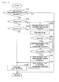
- Fig. 3 is a flow chart showing the flow of the start of the execution of filter regeneration processing according to this embodiment. This flow has been stored in advance in the ECU 10, and is executed by the ECU 10 in a repeated manner.
- step S101 it is determined whether there is a request for the execution of filter regeneration processing. As mentioned above, in this embodiment, each time a predetermined period of time has elapsed after the execution of the last filter regeneration processing ends, the execution of filter regeneration processing is requested. In cases where a negative determination is made in step S101, the execution of this flow is once ended. On the other hand, in cases where an affirmative determination is made in step S101, the processing of step S102 is then carried out.
- step S102 it is determined whether the temperature Tpre of the pre-catalyst 5 is equal to or higher than the predetermined first activation temperature Tc1.
- the first activation temperature Tc1 has been set based on experiments, etc., and stored in the ECU 10 in advance. In cases where the temperature Tpre of the pre-catalyst 5 is lower than the first activation temperature Tc1, even if fuel is added from the fuel addition valve 4, the fuel is difficult to be oxidized in the pre-catalyst 5. For that reason, in cases where a negative determination is made in step S102, the execution of this flow is once ended. On the other hand, in cases where an affirmative determination is made in step S102, the processing of step S103 is then carried out.
- step S103 it is determined whether the temperature Tpost of the post-catalyst 8 is equal to or higher than the predetermined second activation temperature Tc2.
- the second activation temperature Tc2 has been set based on experiments, etc., and stored in the ECU 10 in advance.
- step S104 addition of fuel from the fuel addition valve 4 is carried out. That is, the execution of filter regeneration processing is started.
- step S105 the exhaust gas temperature raising control is carried out.
- An amount of rise in the temperature of the exhaust gas at this time may be set according to the temperature Tpost of the post-catalyst 8, the operating state of the internal combustion engine 1, etc., or may be a fixed amount which has been set in advance.
- step S106 the exhaust gas flow rate increasing control is carried out.
- An amount of increase in the flow rate of the exhaust gas at this time may be set according to the temperature Tpost of the post-catalyst 8, the operating state of the internal combustion engine 1, etc., or may be a fixed amount which has been set in advance.
- step S107 it is determined again whether the temperature Tpost of the post-catalyst 8 is equal to or higher than the second activation temperature Tc2.
- step S105 the processing of step S105 and the processing of step S106 are then carried out again. That is, the execution of the exhaust gas temperature raising control and the exhaust gas flow rate increasing control is continued.
- step S107 the processing of step S108 and the processing of step S109 are then carried out.
- step S108 the execution of the exhaust gas temperature raising control is stopped.
- step S109 the execution of the exhaust gas flow rate increasing control is stopped. Thereafter, the processing of step S104 is carried out. That is, the execution of the filter regeneration processing is started.
- the execution of filter regeneration control is started in a state where the temperature of the post-catalyst 8 is equal to or higher than the second activation temperature.
- the temperature rise of the post-catalyst 8 is promoted by the execution of the exhaust gas temperature raising control and the exhaust gas flow rate increasing control.
- filter regeneration processing may be carried out by performing the exhaust gas temperature raising control in addition to the addition of fuel from the fuel addition valve 4.
- Fig. 4 is a flow chart showing the flow of the start of the execution of filter regeneration processing according to this second embodiment.
- reference will be made only to different features from the flow of the start of the execution of filter regeneration processing according to the first embodiment.
- Fig. 4 for those steps in which the same processes as in the respective steps in the flow chart shown in Fig. 3 , the same reference numerals and characters are attached and an explanation thereof is omitted.
- the schematic construction of intake and exhaust systems of an internal combustion engine according to this second embodiment is the same as that in the first embodiment.
- step S206 the processing of step S206 is carried out after the processing of step S105.
- step S206 it is determined whether the temperature Tf of the SCRF 7 is equal to or higher than a predetermined third activation temperature Tc3. In cases where an affirmative determination is made in step S206, the processing of step S106 is then carried out. That is, the exhaust gas flow rate increasing control is carried out. On the other hand, in cases where a negative determination is made in step S206, the processing of step S107 is then carried out, without performing the processing of step S106. That is, the execution of the exhaust gas flow rate increasing control is inhibited.
- the amount of NOx flowing into the SCRF 7 increases.
- the rate of NOx reduction in the SCR catalyst 7a supported on the SCRF 7 i.e. , the ratio of the amount of NOx reduced in the SCR catalyst 7a with respect to the amount of NOx flowing into the SCRF 7
- the amount of discharge of NOx to the outside may increase to an excessive extent.
- the third activation temperature is a temperature at which it can be judged that the NOx reduction function of the SCR catalyst 7a is activated to such an extent that even if the exhaust gas flow rate increasing control is carried out, the amount of discharge of NOx to the outside falls within an allowable range.
- This third activation temperature is a temperature which is decided according to the kind and configuration of the SCR catalyst 7a, and has been set in advance based on experiments, etc.
- this third activation temperature corresponds to a predetermined filter temperature according to the present invention.
- an amount of increase in the flow rate of the exhaust gas in the exhaust gas flow rate increasing control may also be made small.
- the exhaust gas flow rate increasing control may be carried out, by making the amount of increase in the flow rate of the exhaust gas smaller in comparison with the case where an affirmative determination is made in the step S206.
- Fig. 5 is a flow chart showing the flow of the start of the execution of filter regeneration processing according to this third embodiment.
- reference will be made only to different features from the flow of the start of the execution of filter regeneration processing according to the first embodiment.
- Fig. 5 for those steps in which the same processes as in the respective steps in the flow chart shown in Fig. 3 , the same reference numerals and characters are attached and an explanation thereof is omitted.
- the schematic construction of intake and exhaust systems of an internal combustion engine according to this third embodiment is the same as that in the first embodiment.
- step S306 the processing of step S306 is carried out after the processing of step S105.
- step S306 the rate of NOx reduction Rp in the SCR catalyst 7a supported on the SCRF 7 is calculated.
- the amount of NOx in the exhaust gas flowing into the SCRF 7 can be estimated based on the operating state of the internal combustion engine 1, etc.
- the amount of NOx in the exhaust gas flowing out from the SCRF 7 can be detected by means of the NOx sensor 15.
- the rate of NOx reduction Rp in the SCR catalyst 7a can be calculated based on the estimated value and the detected value of the amount of NOx.
- an NOx sensor may also be arranged in the exhaust passage 3 at the upstream side of the SCRF 7, so that the amount of NOx in the exhaust gas flowing into the SCRF 7 may be detected by this NOx sensor.
- step S307 it is determined whether the rate of NOx reduction Rp in the SCR catalyst 7a is equal to or more than a predetermined rate of reduction Rp0. In cases where an affirmative determination is made in step S307, the processing of step S106 is then carried out. That is, the exhaust gas flow rate increasing control is carried out. On the other hand, in cases where a negative determination is made in step S307, the processing of step S107 is then carried out, without performing the processing of step S106. That is, the execution of the exhaust gas flow rate increasing control is inhibited.
- the predetermined rate of reduction is a rate of NOx reduction in which even if the amount of NOx flowing into the SCRF 7 is increased by carrying out the exhaust gas flow rate increasing control, the amount of discharge of NOx to the outside falls within the allowable range.
- This predetermined rate of reduction is a value which is decided according to the kind and configuration of the SCR catalyst 7a, and has been set in advance based on experiments, etc.
- an amount of increase in the flow rate of the exhaust gas in the exhaust gas flow rate increasing control may also be made small.
- the exhaust gas flow rate increasing control may be carried out, by making the amount of increase in the flow rate of the exhaust gas smaller in comparison with the case where an affirmative determination is made in the step S307.
Abstract
Description
- The present invention relates to an exhaust gas purification system for an internal combustion engine.
- In the past, as an exhaust gas purification apparatus arranged in an exhaust passage of an internal combustion engine, there has been developed one in which a filter that supports thereon an NOx selective reduction catalyst (hereinafter, referred to as an SCR catalyst) (see, for example, Patent literature 1). The filter traps particulate matter (hereinafter, referred to as PM) in exhaust gas. The SCR catalyst serves to reduce NOx in the exhaust gas by using ammonia (NH3) as a reducing agent. Hereinafter, a filter supporting such an SCR catalyst thereon may also be referred to as an SCRF.
- By adopting the SCRF as an exhaust gas purification apparatus, the size of the exhaust gas purification apparatus can be made smaller in comparison with the case where the filter and the SCR catalyst are separately arranged in the exhaust passage. As a result, mountability of the exhaust gas purification apparatus can be improved. In addition, by the adoption of the SCRF, it becomes possible to arrange the SCR catalyst at a location more upstream in the exhaust passage. At the more upstream side in the exhaust passage, the SCR catalyst is arranged, the easier it becomes for the SCR catalyst to be heated by the heat of the exhaust gas. For that reason, it is possible to attain an improvement in the warm-up performance of the SCR catalyst as well as an improvement in the rate of NOx reduction in the SCR catalyst.
- Here, the PM trapped by the SCRF deposits or accumulates therein. For that reason, in an exhaust gas purification system provided with the SCRF, filter regeneration processing is carried out. The filter regeneration processing is to oxidize and remove the PM deposited in the SCRF. The filter regeneration processing is achieved by supplying fuel to a pre-catalyst having an oxidation function which is arranged in the exhaust passage at the upstream side of the SCRF. When the fuel is oxidized in the pre-catalyst, the exhaust gas flowing into the SCRF will be heated by the heat of oxidation. For that reason, the temperature of the SCRF can be raised to a filter regeneration temperature at which the oxidation of the PM is promoted.
- Patent Literature 1: Japanese Unexamined Patent Application Publication No.
2007-501353 - Ammonia or a precursor of ammonia is supplied to the SCRF. Then, in the SCR catalyst supported on the SCRF, the NOx in the exhaust gas is reduced by the ammonia, which acts as a reducing agent. Here, when the ammonia is oxidized, there may be generated NOx. It is necessary to suppress the generation of such NOx, so it is difficult for a catalyst of high oxidizing ability to be supported on the SCRF. Accordingly, the SCR catalyst supported on the SCRF has very low oxidizing ability.
- When the above-mentioned filter regeneration processing is carried out, a part of hydrocarbon (HC) and carbon monoxide (CO) contained in the fuel supplied to the pre-catalyst may pass through the pre-catalyst without being oxidized in the pre-catalyst. The HC and CO having passed through the pre-catalyst flow into the SCRF. However, as mentioned above, the SCR catalyst supported on the SCRF has very low oxidizing ability. For that reason, when the HC and CO pass through the pre-catalyst, these HC and CO will also pass through the SCRF.
- In addition, when the filter regeneration processing is executed, the PM deposited in the SCRF is oxidized to generate CO. In the SCRF, this CO is also difficult to be oxidized. Accordingly, at the time of the execution of the filter regeneration processing, there is a fear that the HC and CO contained in the fuel and the CO generated by the oxidation of the PM may flow out of the SCRF.
- The present invention has been made in view of the problems as mentioned above, and has for its obj ect to provide a technology in which in an exhaust gas purification system for an internal combustion engine provided with an SCRF, HC and CO can be suppressed from being discharged to the outside at the time of the execution of filter regeneration processing, and the filter regeneration processing can be carried out in an efficient manner.
- In the present invention, a post-catalyst is arranged in an exhaust passage at the downstream side of an SCRF. The post-catalyst has an oxidation function. Then, when the temperature of the post-catalyst is lower than a predetermined activation temperature at the time the execution of filter regeneration processing is requested, the temperature of the post-catalyst is raised by carrying out control of raising the temperature of the exhaust gas discharged from the internal combustion engine, and control of increasing the flow rate of the exhaust gas, before the execution of the filter regeneration processing.
- More specifically, an exhaust gas purification system for an internal combustion engine according to the present invention comprises:
- a pre-catalyst that is arranged in an exhaust passage of the internal combustion engine and has an oxidation function;
- a fuel supply device that supplies fuel to said pre-catalyst;
- a filter that is arranged in the exhaust passage at a location downstream of said pre-catalyst for trapping particulate matter in exhaust gas, and supports thereon an NOx selective reduction catalyst which serves to reduce NOx in the exhaust gas by using ammonia as a reducing agent;
- an ammonia supply device that supplies ammonia or a precursor of ammonia to said filter;
- a post-catalyst that is arranged in the exhaust passage at a location downstream of said filter, and has an oxidation function; and
- a filter regeneration processing execution unit that carried out filter regeneration processing in which fuel is supplied from said fuel supply device to said pre-catalyst thereby to raise the temperature of said filter to a predetermined filter regeneration temperature at which oxidation of the particulate matter is promoted, whereby the particulate matter deposited in said filter is oxidized and removed;
- wherein when the temperature of said post-catalyst is lower than a predetermined activation temperature at the time the execution of said filter regeneration processing is requested, the temperature of said post-catalyst is raised to a temperature equal to or higher than said predetermined activation temperature by carrying out control of raising the temperature of the exhaust gas discharged from the internal combustion engine, and control of increasing the flow rate of the exhaust gas, before the execution of said filter regeneration processing by said filter regeneration processing execution unit.
- In the exhaust gas purification system for an internal combustion engine according to the present invention, the pre-catalyst, the SCRF (filter) and the post-catalyst are arranged sequentially from an upstream side in the exhaust passage of the internal combustion engine. Then, ammonia or the precursor of ammonia is supplied to the SCRF. In the SCR (NOx selective catalytic reduction) catalyst supported on the SCRF, the NOx in the exhaust gas is reduced by using, as a reducing agent, the ammonia thus supplied or ammonia generated from the precursor of ammonia thus supplied. In addition, the filter regeneration processing for removing the PM deposited in the SCRF is achieved or carried out by supplying fuel from the fuel supply device to the pre-catalyst.
- When the filter regeneration processing is carried out, HC and CO having passed through the pre-catalyst and the SCRF without being oxidized in the pre-catalyst flow into the post-catalyst. At this time, when the oxidation function of the post-catalyst is activated to a sufficient extent, HC and CO can be oxidized in the post-catalyst.
- Accordingly, in the present invention, when the temperature of the post-catalyst is lower than the predetermined activation temperature at the time the execution of filter regeneration processing is requested, the temperature of the post-catalyst is raised to the predetermined activation temperature or above by carrying out the control of raising the temperature of the exhaust gas discharged from the internal combustion engine, and the control of increasing the flow rate of the exhaust gas, before carrying out the filter regeneration processing by means of the filter regeneration processing execution unit (i.e., before carrying out the supply of fuel from the fuel supply device to the pre-catalyst). Here, the predetermined activation temperature is a temperature at which the HC and CO flowing into the post-catalyst can be oxidized to a sufficient extent.
- According to the control of raising the temperature of the exhaust gas discharged from the internal combustion engine, it is possible to raise the temperature of the exhaust gas flowing into the post-catalyst, while suppressing an increase in HC and CO in the exhaust gas in comparison with the case where fuel is supplied from the fuel supply unit to the pre-catalyst. Then, by raising the temperature of the exhaust gas flowing into the post-catalyst, the amount of heat supplied to the post-catalyst by the exhaust gas can be made to increase.
- In addition, by increasing the flow rate of the exhaust gas, it becomes difficult for the amount of heat of the exhaust gas to be taken by the pre-catalyst and the SCRF, which are arranged at the upstream side of the post-catalyst. For that reason, the amount of heat supplied to the post-catalyst by the exhaust gas can be made to increase to a more extent. Accordingly, it becomes possible to promote the rise in temperature of the post-catalyst to a more extent.
- According to the present invention, the filter regeneration processing is carried out when the temperature of the post-catalyst is equal to or more than the predetermined activation temperature. Accordingly, it is possible to suppress HC and CO from being discharged to the outside at the time of the execution of the filter regeneration processing. On the other hand, when the activation of the oxidation function of the post-catalyst is insufficient, it is possible to quickly enhance the oxidation function of the post-catalyst to a sufficient level. Accordingly, it becomes possible to start the execution of the filter regenerationprocessing at an earlier period of time. For that reason, the filter regeneration processing can be carried out in an efficient manner.
- In the present invention, in cases where the temperature of the filter is lower than a predetermined filter temperature when the temperature of the post-catalyst at the time the execution of the filter regeneration processing is requested is lower than the predetermined activation temperature, the execution of the control of increasing the flow rate of the exhaust gas may be inhibited. In addition, in the present invention, in cases where the rate of NOx reduction in the SCR catalyst supported on the SCRF is lower than a predetermined rate of reduction when the temperature of the post-catalyst at the time the execution of the filter regeneration processing is requested is lower than the predetermined activation temperature, the execution of the control of increasing the flow rate of the exhaust gas may be inhibited.
- According to these, it is possible to suppress the amount of NOx flowing into the SCRF from increasing when the rate of NOx reduction in the SCR catalyst supported on the SCRF is in an insufficient state. For that reason, it is also possible to suppress the increase in the amount of discharge of NOx to the outside.
- In the present invention, in cases where the temperature of the filter is lower than a predetermined filter temperature when the temperature of the post-catalyst at the time the execution of the filter regeneration processing is requested is lower than the predetermined activation temperature, an amount of increase at the time of increasing the flow rate of the exhaust gas may also be made smaller than when the temperature of the filter is equal to or higher than the predetermined filter temperature. Moreover, in the present invention, in cases where the rate of NOx reduction in the SCR catalyst supported on the SCRF is lower than a predetermined rate of reduction when the temperature of the post-catalyst at the time the execution of the filter regeneration processing is requested is lower than the predetermined activation temperature, an amount of increase at the time of increasing the flow rate of the exhaust gas may also be made smaller when the rate of NOx reduction in the SCR catalyst is equal to or higher than the predetermined rate of reduction.
- According to these, an excessive increase in the amount of discharge of NOx to the outside can be suppressed, while promoting the temperature rise of the post-catalyst.
- According to the present invention, in an exhaust gas purification system for an internal combustion engine provided with an SCRF, HC and CO can be suppressed from being discharged to the outside at the time of the execution of filter regeneration processing, and the filter regeneration processing can be carried out in an efficient manner.
-
- [
Fig. 1 ] This is a view showing the schematic construction of intake and exhaust systems of an internal combustion engine according to a first embodiment of the present invention. - [
Fig. 2 ] This is a view showing the relation of the temperatures of a pre-catalyst, an SCRF, and a post-catalyst, with respect to the flow rate of exhaust gas when exhaust gas temperature raising control is carried out, according to the first embodiment. - [
Fig. 3 ] This is a flow chart showing a flow of the start of the execution of filter regeneration processing according to the first embodiment. - [
Fig. 4 ] This is a flow chart showing a flow of the start of the execution of filter regeneration processing according to a second embodiment. - [
Fig. 5 ] This is a flow chart showing a flow of the start of the execution of filter regeneration processing according to a third embodiment. - Hereinafter, specific embodiments of the present invention will be described based on the attached drawings. However, the dimensions, materials, shapes, relative arrangements and so on of component parts described in the embodiments are not intended to limit the technical scope of the present invention to these alone in particular as long as there are no specific statements.
- Here, description will be made by taking as an example a case in which an exhaust gas purification system for an internal combustion engine according to the present invention is applied to a diesel engine for driving a vehicle. However, it is to be noted that the internal combustion engine according to the present invention is not limited to a diesel engine, but may be a gasoline engine, etc.
-
Fig. 1 is a view showing the schematic construction of intake and exhaust systems of an internal combustion engine according to this first embodiment. Theinternal combustion engine 1 is a diesel engine for driving a vehicle. Anintake passage 2 and anexhaust passage 3 are connected to theinternal combustion engine 1. In theintake passage 2, there are arranged anair flow meter 11 and athrottle valve 9. Theair flow meter 11 serves to detect an amount of intake air sucked into theinternal combustion engine 1. Thethrottle valve 9 serves to adjust the amount of intake air sucked into theinternal combustion engine 1. - In the
exhaust passage 3, there are arranged afuel addition valve 4, apre-catalyst 5, a first exhaustgas temperature sensor 12, anammonia addition valve 6, anSCRF 7, a second exhaustgas temperature sensor 13, apost-catalyst 8, a third exhaustgas temperature sensor 14, and anNOx sensor 15, sequentially from an upstream side along the flow of exhaust gas. - The
pre-catalyst 5 is an oxidation catalyst. However, thepre-catalyst 5 may be a catalyst other than the oxidation catalyst, as long as it has an oxidation function. In order to supply fuel to thepre-catalyst 5, thefuel addition valve 4 adds fuel into the exhaust gas. - Here, note that in this embodiment, the
fuel addition valve 4 corresponds to a fuel supply device according to the present invention. However, thefuel addition valve 4 may not be provided, but fuel can also be supplied to thepre-catalyst 5 in theinternal combustion engine 1 by carrying out auxiliary fuel injection at the timing at which injected fuel is discharged into theexhaust passage 3 in an unburnt state without being used for combustion. - The
SCRF 7 is constructed such that anSCR catalyst 7a is supported on a wall flow type filter which serves to trap particulate matter (PM) in the exhaust gas. TheSCR catalyst 7a serves to reduce NOx in the exhaust gas by using ammonia as a reducing agent. Theammonia addition valve 6 supplies ammonia gas into the exhaust gas so as to supply ammonia to theSCRF 7. When the ammonia is supplied to theSCRF 7, the ammonia once adsorbs to theSCR catalyst 7a supported on theSCRF 7. Then, the NOx in the exhaust gas is reduced by the adsorbed ammonia acting as a reducing agent. - Here, note that in this embodiment, the
ammonia addition valve 6 corresponds to an ammonia supply device according to the present invention. However, the ammonia supply device according to the present invention may be a device which supplies ammonia as liquid or solid. In addition, the ammonia supply device according to the present invention may be a device which supplies a precursor of ammonia. For example, in this embodiment, in place of theammonia addition valve 6, provision may be made for a urea addition valve that serves to add an aqueous urea solution into the exhaust gas. In this case, urea is supplied to theSCRF 7 as the precursor of ammonia. Then, the urea is hydrolyzed to generate ammonia. - The
post-catalyst 8 is an oxidation catalyst. However, thepost-catalyst 8 may be another catalyst having an oxidation function. In addition, thepost-catalyst 8 may be a catalyst which is composed by combining an oxidation catalyst and an SCR catalyst which serves to reduce the NOx in the exhaust gas by using ammonia as a reducing agent. In this case, the oxidation catalyst may be formed, for example, by carrying a precious metal such as platinum (Pt), etc., on a carrier made of a material such as aluminum oxide (Al2O3), zeolite, etc., and the SCR catalyst may be formed by carrying a base metal such as copper (Cu), iron (Fe), etc., on a carrier made of a material such as zeolite. By forming the post-catalyst 8 into the catalyst of such a configuration, HC, CO and ammonia in the exhaust gas can be oxidized, and further, a part of ammonia is oxidized to generate NOx, and the NOx thus generated can also be reduced by using excessive or surplus ammonia as a reducing agent. - The first exhaust
gas temperature sensor 12, the second exhaustgas temperature sensor 13, and the third exhaustgas temperature sensor 14 are each a sensor for detecting the temperature of the exhaust gas. The first exhaustgas temperature sensor 12 detects the temperature of the exhaust gas which flows out from thepre-catalyst 5. The second exhaustgas temperature sensor 13 detects the temperature of the exhaust gas which flows out from theSCRF 7. The third exhaustgas temperature sensor 14 detects the temperature of the exhaust gas which flows out from thepost-catalyst 8. TheNOx sensor 15 detects the amount of NOx in the exhaust gas. - In addition, an
EGRpassage 16 has one end thereof connected to theexhaust passage 3 at a location upstream of thefuel addition valve 4. TheEGR passage 16 has the other end thereof connected to theintake passage 2 at a location downstream of thethrottle valve 9. Moreover, anEGR valve 17 is arranged in theEGR passage 16. - According to such a construction, a part of the exhaust gas discharged from the
internal combustion engine 1 is introduced as EGR gas into theintake passage 2 through theEGR passage 16. With this, the EGR gas is supplied to theinternal combustion engine 1. In addition, the flow rate of the EGR gas introduced into theintake passage 2 through theEGR passage 16 is adjusted by means of theEGR valve 17. - An electronic control unit (ECU) 10 is provided in combination with the
internal combustion engine 1. TheECU 10 is electrically connected to a variety of kinds of sensors such as theair flow meter 11, the first exhaustgas temperature sensor 12, the second exhaustgas temperature sensor 13, the third exhaustgas temperature sensor 14, theNOx sensor 15, and so on. Then, output signals of these various kinds of sensors are inputted to theECU 10. TheECU 10 estimates the flow rate of the exhaust gas in theexhaust passage 3 based on the output value of theair flow meter 11. Further, theECU 10 estimates the temperature of the pre-catalyst 5 based on the output value of the first exhaustgas temperature sensor 12, the temperature of the SCRF 7 (i.e., the temperature of theSCR catalyst 7a) based on the output value of the second exhaustgas temperature sensor 13, and the temperature of the post-catalyst 8 based on the output value of the third exhaustgas temperature sensor 14. - Further, the
throttle valve 9, thefuel addition valve 4, theammonia addition valve 6, and theEGR valve 17 are electrically connected to theECU 10. Then, these valves are controlled by means of theECU 10. - In the
SCRF 7, particulate matter (PM) trapped thereby gradually deposits or accumulates therein. Accordingly, in this embodiment, filter regeneration processing is carried out by means of theECU 10 in order to remove the PM deposited in theSCRF 7. The filter regeneration processing according to this embodiment is achieved by adding fuel into the exhaust gas from thefuel addition valve 4 thereby to supply the fuel to thepre-catalyst 5. - When fuel is oxidized in the
pre-catalyst 5, heat of oxidation is generated. The exhaust gas flowing into theSCRF 7 is heated by this heat of oxidation. As a result of this, the temperature ofSCRF 7 goes up. At the time of carrying out the filter regeneration processing, by controlling the amount of fuel to be added from thefuel addition valve 4, the temperature of theSCRF 7 is caused to rise to a predetermined filter regeneration temperature (e.g., 600 - 650 degrees C) at which the oxidation of the PM is promoted. As a result, the PM deposited in theSCRF 7 is oxidized and removed. - In this embodiment, each time a predetermined period of time elapses after the execution of the last filter regeneration processing ends, the execution of the filter regeneration processing is requested. Here, note that each time the vehicle with the
internal combustion engine 1 mounted thereon travels a predetermined travel distance, the execution of the filter regeneration processing may also instead be requested. In addition, each time the amount of PM deposition in theSCRF 7 reaches a predetermined amount of deposition, the execution of the filter regeneration processing may also be requested. The amount of PM deposition in theSCRF 7 can be estimated based on the histories of the amount of fuel injection in theinternal combustion engine 1, the flow rate of the exhaust gas flowing into theSCRF 7, the temperature of theSCRF 7, and so on. - Then, in cases where the temperature of the
pre-catalyst 5 is higher than a predetermined first activation temperature at the time the execution of the filter regeneration processing is requested, the filter regeneration processing is carried out (i.e., the addition of fuel from thefuel addition valve 4 is carried out). Here, the first activation temperature is a temperature at which the fuel added from thefuel addition valve 4 can be oxidized in thepre-catalyst 5 to a certain extent. This first activation temperature is a temperature which is decided according to the kind and configuration of thepre-catalyst 5, and has been set in advance based on experiments, etc. - When the filter regeneration processing is carried out by adding fuel from the
fuel addition valve 4, a part of hydrocarbon (HC) and carbon monoxide (CO) contained in the fuel supplied to thepre-catalyst 5 may pass through thepre-catalyst 5 without being oxidized in thepre-catalyst 5. The HC and CO having passed through thepre-catalyst 5 flow into theSCRF 7. However, theSCR catalyst 7a supported on theSCRF 7 has very low oxidizing ability, so the HC and CO are difficult to be oxidized in theSCR catalyst 7a. For that reason, the HC and CO having passed through thepre-catalyst 5 will also pass through theSCRF 7. - In addition, when the filter regeneration processing is executed, the PM deposited in the
SCRF 7 is oxidized to generate CO. In theSCRF 7, this CO is also difficult to be oxidized. Accordingly, at the time of the execution of the filter regeneration processing, there is a fear that the HC and CO contained in the fuel and the CO generated by the oxidation of the PM may flow out of theSCRF 7. - Here, in this embodiment, the
post-catalyst 8 is arranged in theexhaust passage 3 at the downstream side of theSCRF 7. When the filter regeneration processing is carried out, the HC and CO having passed through thepre-catalyst 5 and theSCRF 7 without being oxidized in thepre-catalyst 5 flow into thepost-catalyst 8. At this time, when the oxidation function of thepost-catalyst 8 is activated to a sufficient extent, the HC and CO can be oxidized in thepost-catalyst 8. - Accordingly, in this embodiment, when the temperature of the
post-catalyst 8 is lower than a predetermined second activation temperature at the time the execution of the filter regeneration processing is requested, the temperature of the post-catalyst is raised to the predetermined activation temperature or above by performing exhaust gas temperature raising control and exhaust gas flow rate increasing control, before carrying out the filter regeneration processing (i.e., before carrying out the addition of fuel from the fuel addition valve 4). - Here, the second activation temperature is a temperature at which the HC and CO flowing into the
post-catalyst 8 can be oxidized to a sufficient extent in thepost-state catalyst 8. This second activation temperature is a temperature which is decided according to the kind and configuration of thepost-catalyst 8, and has been set in advance based on experiments, etc. Here, note that in this embodiment, this second activation temperature corresponds to a predetermined activation temperature according to the present invention. - The exhaust gas temperature raising control is the control of raising the temperature of the exhaust gas discharged from the
internal combustion engine 1. As this exhaust gas temperature raising control, there can be mentioned, by way of example, the control of carrying out an auxiliary fuel injection at the timing which is later than a main combustion injection in one combustion cycle and at which injected fuel is provided to combustion, in theinternal combustion engine 1. - The exhaust gas flow rate increasing control is the control of increasing the flow rate of the exhaust gas flowing through the
exhaust passage 3. As the exhaust gas flow rate increasing control, there can be mentioned, by way of example, the control of increasing the amount of intake air by making large the degree of opening of thethrottle valve 9, or the control of decreasing the amount of EGR gas by making small the degree of opening of theEGR valve 17. - By raising the temperature of the exhaust gas discharged from the
internal combustion engine 1 by means of the exhaust gas temperature raising control, it is possible to raise the temperature of the exhaust gas flowing into thepost-catalyst 8, while suppressing an increase in HC and CO in the exhaust gas, in comparison with the case where fuel is added from thefuel addition valve 4 and the fuel thus added is oxidized in thepre-catalyst 5. Then, by raising the temperature of the exhaust gas flowing into thepost-catalyst 8, the amount of heat supplied to thepost-catalyst 8 by the exhaust gas can be made to increase. - Moreover, by increasing the flow rate of the exhaust gas flowing through the
exhaust passage 3 by means of the exhaust gas flow rate increasing control, it becomes difficult for the amount of heat of the exhaust gas to be taken by thepre-catalyst 5 and theSCRF 7, which are arranged at the upstream side of thepost-catalyst 8. In other words, it is possible to keep higher the temperature of the exhaust gas flowing into thepost-catalyst 8. For that reason, the amount of heat supplied to thepost-catalyst 8 by the exhaust gas can be made to increase to a more extent. Accordingly, it becomes possible to promote the rise in temperature of the post-catalyst 8 to a more extent. -
Fig. 2 is a view showing the relation of the temperatures of thepre-catalyst 5, theSCRF 7 and thepost-catalyst 8, with respect to the flow rate of the exhaust gas when the exhaust gas temperature raising control is carried out, according to the first embodiment. InFig. 2 , a broken line shows the temperatures when the flow rate of the exhaust gas is relatively small , and a solid line shows the temperatures when the flow rate of the exhaust gas is relatively large. As shown inFig. 2 , at the time of the execution of the filter regeneration processing, the temperature of thepost-catalyst 8 becomes higher when the flow rate of the exhaust gas is large, in comparison with the time when the flow rate of the exhaust gas is small. - According to the above, the filter regeneration processing is carried out when the temperature of the
post-catalyst 8 is equal to or more than the second activation temperature. In other words, the filter regeneration processing is carried out under the state where the oxidizing ability of thepost-catalyst 8 has been activated to a sufficient extent. Accordingly, it is possible to suppress HC and CO from being discharged to the outside at the time of the execution of the filter regeneration processing. - Further, when the activation of the oxidation function of the
post-catalyst 8 is insufficient at the time the execution of the filter regeneration processing has been requested, it is possible to quickly enhance the oxidation function of the post-catalyst 8 to a sufficient level. Accordingly, it becomes possible to start the execution of the filter regeneration processing at an earlier period of time. For that reason, the filter regeneration processing can be carried out in an efficient manner. - Here, reference will be made to a flow of the start of the execution of filter regeneration processing according to this embodiment, based on
Fig. 3. Fig. 3 is a flow chart showing the flow of the start of the execution of filter regeneration processing according to this embodiment. This flow has been stored in advance in theECU 10, and is executed by theECU 10 in a repeated manner. - In this flow, first in step S101, it is determined whether there is a request for the execution of filter regeneration processing. As mentioned above, in this embodiment, each time a predetermined period of time has elapsed after the execution of the last filter regeneration processing ends, the execution of filter regeneration processing is requested. In cases where a negative determination is made in step S101, the execution of this flow is once ended. On the other hand, in cases where an affirmative determination is made in step S101, the processing of step S102 is then carried out.
- In step S102, it is determined whether the temperature Tpre of the
pre-catalyst 5 is equal to or higher than the predetermined first activation temperature Tc1. As stated above, the first activation temperature Tc1 has been set based on experiments, etc., and stored in theECU 10 in advance. In cases where the temperature Tpre of thepre-catalyst 5 is lower than the first activation temperature Tc1, even if fuel is added from thefuel addition valve 4, the fuel is difficult to be oxidized in thepre-catalyst 5. For that reason, in cases where a negative determination is made in step S102, the execution of this flow is once ended. On the other hand, in cases where an affirmative determination is made in step S102, the processing of step S103 is then carried out. - In step S103, it is determined whether the temperature Tpost of the
post-catalyst 8 is equal to or higher than the predetermined second activation temperature Tc2. As stated above, the second activation temperature Tc2 has been set based on experiments, etc., and stored in theECU 10 in advance. In cases where an affirmative determination is made in step S103, then in step S104, addition of fuel from thefuel addition valve 4 is carried out. That is, the execution of filter regeneration processing is started. - On the other hand, in cases where a negative determination is made in step S103, the processing of step S105 is then carried out. In step S105, the exhaust gas temperature raising control is carried out. An amount of rise in the temperature of the exhaust gas at this time may be set according to the temperature Tpost of the
post-catalyst 8, the operating state of theinternal combustion engine 1, etc., or may be a fixed amount which has been set in advance. - Subsequently, in step S106, the exhaust gas flow rate increasing control is carried out. An amount of increase in the flow rate of the exhaust gas at this time may be set according to the temperature Tpost of the
post-catalyst 8, the operating state of theinternal combustion engine 1, etc., or may be a fixed amount which has been set in advance. - Then, in step S107, it is determined again whether the temperature Tpost of the
post-catalyst 8 is equal to or higher than the second activation temperature Tc2. In cases where a negative determination is made in step S107, the processing of step S105 and the processing of step S106 are then carried out again. That is, the execution of the exhaust gas temperature raising control and the exhaust gas flow rate increasing control is continued. - On the other hand, in cases where an affirmative determination is made in step S107, the processing of step S108 and the processing of step S109 are then carried out. In step S108, the execution of the exhaust gas temperature raising control is stopped. In step S109, the execution of the exhaust gas flow rate increasing control is stopped. Thereafter, the processing of step S104 is carried out. That is, the execution of the filter regeneration processing is started.
- According to the above-mentioned flow, the execution of filter regeneration control is started in a state where the temperature of the
post-catalyst 8 is equal to or higher than the second activation temperature. In addition, when the temperature of thepost-catalyst 8 is lower than the second activation temperature at the time the execution of filter regeneration processing is requested, the temperature rise of thepost-catalyst 8 is promoted by the execution of the exhaust gas temperature raising control and the exhaust gas flow rate increasing control. - Here, note that in this embodiment, also in cases where the temperature of the
pre-catalyst 5 is equal to or more than the first activation temperature and the temperature of thepost-catalyst 8 is equal to or more than the second activation temperature, at the time when the execution of filter regeneration processing is requested, filter regeneration processing may be carried out by performing the exhaust gas temperature raising control in addition to the addition of fuel from thefuel addition valve 4. - Reference will be made to a flow of the start of the execution of filter regeneration processing according to this second embodiment, based on
Fig. 4. Fig. 4 is a flow chart showing the flow of the start of the execution of filter regeneration processing according to this second embodiment. Here, reference will be made only to different features from the flow of the start of the execution of filter regeneration processing according to the first embodiment. InFig. 4 , for those steps in which the same processes as in the respective steps in the flow chart shown inFig. 3 , the same reference numerals and characters are attached and an explanation thereof is omitted. Here, note that the schematic construction of intake and exhaust systems of an internal combustion engine according to this second embodiment is the same as that in the first embodiment. - In this flow, the processing of step S206 is carried out after the processing of step S105. In step S206, it is determined whether the temperature Tf of the
SCRF 7 is equal to or higher than a predetermined third activation temperature Tc3. In cases where an affirmative determination is made in step S206, the processing of step S106 is then carried out. That is, the exhaust gas flow rate increasing control is carried out. On the other hand, in cases where a negative determination is made in step S206, the processing of step S107 is then carried out, without performing the processing of step S106. That is, the execution of the exhaust gas flow rate increasing control is inhibited. - When the flow rate of the exhaust gas flowing through the
exhaust passage 3 is made to increase by the exhaust gas flow rate image control, the amount of NOx flowing into theSCRF 7 increases. At this time, when the rate of NOx reduction in theSCR catalyst 7a supported on the SCRF 7 (i.e. , the ratio of the amount of NOx reduced in theSCR catalyst 7a with respect to the amount of NOx flowing into the SCRF 7) is insufficient, the amount of discharge of NOx to the outside may increase to an excessive extent. - Accordingly, in this embodiment, as in the above-mentioned flow, in cases where the temperature of the
SCRF 7 is lower than the third activation temperature, even at the time when the temperature of thepost-catalyst 8 is lower than a second predetermined temperature, the execution of the exhaust gas flow rate increasing control is inhibited. Here, the third activation temperature is a temperature at which it can be judged that the NOx reduction function of theSCR catalyst 7a is activated to such an extent that even if the exhaust gas flow rate increasing control is carried out, the amount of discharge of NOx to the outside falls within an allowable range. This third activation temperature is a temperature which is decided according to the kind and configuration of theSCR catalyst 7a, and has been set in advance based on experiments, etc. Here, note that in this embodiment, this third activation temperature corresponds to a predetermined filter temperature according to the present invention. - According to this embodiment, it is possible to suppress the amount of NOx flowing into the
SCRF 7 from increasing when the rate of NOx reduction in theSCR catalyst 7a supported on theSCRF 7 is in an insufficient state. For that reason, it is also possible to suppress the increase in the amount of discharge of NOx to the outside. - In a flow of the start of the execution of filter regeneration processing according to this modification, instead of inhibiting the execution of the exhaust gas flow rate increasing control, an amount of increase in the flow rate of the exhaust gas in the exhaust gas flow rate increasing control may also be made small. In other words, in cases where a negative determination is made in step S206 in the flow shown in
Fig. 4 , the exhaust gas flow rate increasing control may be carried out, by making the amount of increase in the flow rate of the exhaust gas smaller in comparison with the case where an affirmative determination is made in the step S206. - According to this, an excessive increase in the amount of discharge of NOx to the outside can be suppressed, while promoting the temperature rise of the
post-catalyst 8. - Reference will be made to a flow of the start of the execution of filter regeneration processing according to this third embodiment, based on
Fig. 5. Fig. 5 is a flow chart showing the flow of the start of the execution of filter regeneration processing according to this third embodiment. Here, reference will be made only to different features from the flow of the start of the execution of filter regeneration processing according to the first embodiment. InFig. 5 , for those steps in which the same processes as in the respective steps in the flow chart shown inFig. 3 , the same reference numerals and characters are attached and an explanation thereof is omitted. Here, note that the schematic construction of intake and exhaust systems of an internal combustion engine according to this third embodiment is the same as that in the first embodiment. - In this flow, the processing of step S306 is carried out after the processing of step S105. In step S306, the rate of NOx reduction Rp in the
SCR catalyst 7a supported on theSCRF 7 is calculated. The amount of NOx in the exhaust gas flowing into theSCRF 7 can be estimated based on the operating state of theinternal combustion engine 1, etc. In addition, the amount of NOx in the exhaust gas flowing out from theSCRF 7 can be detected by means of theNOx sensor 15. The rate of NOx reduction Rp in theSCR catalyst 7a can be calculated based on the estimated value and the detected value of the amount of NOx. Here, note that an NOx sensor may also be arranged in theexhaust passage 3 at the upstream side of theSCRF 7, so that the amount of NOx in the exhaust gas flowing into theSCRF 7 may be detected by this NOx sensor. - Subsequently, in step S307, it is determined whether the rate of NOx reduction Rp in the
SCR catalyst 7a is equal to or more than a predetermined rate of reduction Rp0. In cases where an affirmative determination is made in step S307, the processing of step S106 is then carried out. That is, the exhaust gas flow rate increasing control is carried out. On the other hand, in cases where a negative determination is made in step S307, the processing of step S107 is then carried out, without performing the processing of step S106. That is, the execution of the exhaust gas flow rate increasing control is inhibited. - Here, the predetermined rate of reduction is a rate of NOx reduction in which even if the amount of NOx flowing into the
SCRF 7 is increased by carrying out the exhaust gas flow rate increasing control, the amount of discharge of NOx to the outside falls within the allowable range. This predetermined rate of reduction is a value which is decided according to the kind and configuration of theSCR catalyst 7a, and has been set in advance based on experiments, etc. - According to the above-mentioned flow, in cases where the rate of NOx reduction in the
SCR catalyst 7a is lower than the predetermined rate of reduction, even at the time when the temperature of thepost-catalyst 8 is lower than the second predetermined temperature, the execution of the exhaust gas flow rate increasing control is inhibited. Accordingly, similar to the flow according to the second embodiment, it is possible to suppress the amount of NOx flowing into theSCRF 7 from increasing when the rate of NOx reduction in theSCR catalyst 7a supported on theSCRF 7 is in an insufficient state. For that reason, it is also possible to suppress the increase in the amount of discharge of NOx to the outside. - In a flow of the start of the execution of filter regeneration processing according to this modification, similar to the flow according to the second embodiment, instead of inhibiting the execution of the exhaust gas flow rate increasing control, an amount of increase in the flow rate of the exhaust gas in the exhaust gas flow rate increasing control may also be made small. In other words, in cases where a negative determination is made in step S307 in the flow shown in
Fig. 5 , the exhaust gas flow rate increasing control may be carried out, by making the amount of increase in the flow rate of the exhaust gas smaller in comparison with the case where an affirmative determination is made in the step S307. - According to this, an excessive increase in the amount of discharge of NOx to the outside can be suppressed, while promoting the temperature rise of the
post-catalyst 8. -
- 1 ... internal combustion engine
- 2 ... intake passage
- 3 ... exhaust passage
- 4 ... fuel addition valve
- 5 ... pre-catalyst
- 6 ... ammonia addition valve
- 7 ... filter (SCRF)
- 7a .. NOx selective reduction catalyst (SCR catalyst)
- 8 ... post-catalyst
- 9 ... throttle valve
- 10 .. ECU
- 11 .. air flow meter
- 12 .. first exhaust gas temperature sensor
- 13 .. second exhaust gas temperature sensor
- 14 .. third exhaust gas temperature sensor
- 15 ... NOx sensor
- 16 ... EGR passage
- 17 ... EGR valve
Claims (3)
- An exhaust gas purification system for an internal combustion engine comprising:a pre-catalyst that is arranged in an exhaust passage of the internal combustion engine and has an oxidation function;a fuel supply device that supplies fuel to said pre-catalyst;a filter that is arranged in the exhaust passage at a location downstream of said pre-catalyst for trapping particulate matter in exhaust gas, and supports thereon an NOx selective reduction catalyst which serves to reduce NOx in the exhaust gas by using ammonia as a reducing agent;an ammonia supply device that supplies ammonia or a precursor of ammonia to said filter;a post-catalyst that is arranged in the exhaust passage at a location downstream of said filter, and has an oxidation function; anda filter regeneration processing execution unit that carried out filter regeneration processing in which fuel is supplied from said fuel supply device to said pre-catalyst thereby to raise the temperature of said filter to a predetermined filter regeneration temperature at which oxidation of the particulate matter is promoted, whereby the particulate matter deposited in said filter is oxidized and removed;wherein when the temperature of said post-catalyst is lower than a predetermined activation temperature at the time the execution of said filter regeneration processing is requested, the temperature of said post-catalyst is raised to a temperature equal to or higher than said predetermined activation temperature by carrying out control of raising the temperature of the exhaust gas discharged from the internal combustion engine, and control of increasing the flow rate of the exhaust gas, before the execution of said filter regeneration processing by said filter regeneration processing execution unit.
- The exhaust gas purification system for an internal combustion engine as set forth in claim 1, wherein in cases where the temperature of said filter is lower than a predetermined filter temperature when the temperature of said post-catalyst at the time the execution of said filter regeneration processing is requested is lower than said predetermined activation temperature, the execution of the control of increasing the flow rate of the exhaust gas is inhibited, or an amount of increase at the time of increasing the flow rate of the exhaust gas may also be made smaller than when the temperature of said filter is equal to or higher than said predetermined filter temperature.
- The exhaust gas purification system for an internal combustion engine as set forth in claim 1, wherein in cases where the rate of NOx reduction in said NOx selective reduction catalyst supported on said filter is lower than a predetermined rate of reduction when the temperature of said post-catalyst at the time the execution of said filter regeneration processing is requested is lower than said predetermined activation temperature, the execution of the control of increasing the flow rate of the exhaust gas is inhibited, or an amount of increase at the time of increasing the flow rate of the exhaust gas is made smaller than when the rate of NOx reduction in said NOx selective reduction catalyst is equal to or more than said predetermined rate of reduction.
Applications Claiming Priority (1)
| Application Number | Priority Date | Filing Date | Title |
|---|---|---|---|
| PCT/JP2012/081266 WO2014087466A1 (en) | 2012-12-03 | 2012-12-03 | Exhaust purification system for internal combustion engine |
Publications (3)
| Publication Number | Publication Date |
|---|---|
| EP2927445A1 true EP2927445A1 (en) | 2015-10-07 |
| EP2927445A4 EP2927445A4 (en) | 2015-12-16 |
| EP2927445B1 EP2927445B1 (en) | 2017-03-22 |
Family
ID=50882919
Family Applications (1)
| Application Number | Title | Priority Date | Filing Date |
|---|---|---|---|
| EP12889659.4A Active EP2927445B1 (en) | 2012-12-03 | 2012-12-03 | Exhaust gas purification system for internal combustion engine |
Country Status (5)
| Country | Link |
|---|---|
| US (1) | US9464554B2 (en) |
| EP (1) | EP2927445B1 (en) |
| JP (1) | JP5900653B2 (en) |
| CN (1) | CN104838100B (en) |
| WO (1) | WO2014087466A1 (en) |
Cited By (1)
| Publication number | Priority date | Publication date | Assignee | Title |
|---|---|---|---|---|
| US11143073B2 (en) * | 2017-03-22 | 2021-10-12 | Ford Global Technologies, Llc | Methods and systems for a diesel oxidation catalyst |
Families Citing this family (3)
| Publication number | Priority date | Publication date | Assignee | Title |
|---|---|---|---|---|
| JP2016084781A (en) * | 2014-10-28 | 2016-05-19 | 本田技研工業株式会社 | Exhaust emission control system for internal combustion engine |
| CN105879508B (en) * | 2016-05-24 | 2019-01-15 | 河南龙成煤高效技术应用有限公司 | The dust pelletizing system and its dust removal method that cleaner, the cleaner for the atm number gas that dustiness is 100-2000g/m3, tar content is 100-3000g/m3 form |
| FR3071871B1 (en) * | 2017-09-29 | 2020-02-07 | Continental Automotive France | SELECTIVE CATALYTIC REDUCTION PROCESS WITH AMMONIA DESORPTION FROM A CARTRIDGE IN AN EXHAUST LINE |
Family Cites Families (8)
| Publication number | Priority date | Publication date | Assignee | Title |
|---|---|---|---|---|
| JP2004060494A (en) * | 2002-07-26 | 2004-02-26 | Toyota Motor Corp | Exhaust emission control device of internal combustion engine |
| US7229597B2 (en) * | 2003-08-05 | 2007-06-12 | Basfd Catalysts Llc | Catalyzed SCR filter and emission treatment system |
| JP2007255310A (en) * | 2006-03-23 | 2007-10-04 | Mitsubishi Fuso Truck & Bus Corp | Exhaust emission control device |
| JP5118331B2 (en) * | 2006-11-15 | 2013-01-16 | 三菱ふそうトラック・バス株式会社 | Exhaust purification device |
| JP2009264278A (en) * | 2008-04-25 | 2009-11-12 | Toyota Motor Corp | Exhaust emission control device of internal combustion engine |
| JP2011052611A (en) * | 2009-09-02 | 2011-03-17 | Toyota Industries Corp | Device for controlling exhaust emission |
| US20110064632A1 (en) * | 2009-09-14 | 2011-03-17 | Ford Global Technologies, Llc | Staged Catalyst System and Method of Using the Same |
| JP2011196311A (en) * | 2010-03-23 | 2011-10-06 | Mazda Motor Corp | Exhaust emission purifying method and exhaust emission purifying apparatus |
-
2012
- 2012-12-03 WO PCT/JP2012/081266 patent/WO2014087466A1/en active Application Filing
- 2012-12-03 US US14/648,727 patent/US9464554B2/en not_active Expired - Fee Related
- 2012-12-03 EP EP12889659.4A patent/EP2927445B1/en active Active
- 2012-12-03 JP JP2014550816A patent/JP5900653B2/en active Active
- 2012-12-03 CN CN201280077488.7A patent/CN104838100B/en active Active
Cited By (1)
| Publication number | Priority date | Publication date | Assignee | Title |
|---|---|---|---|---|
| US11143073B2 (en) * | 2017-03-22 | 2021-10-12 | Ford Global Technologies, Llc | Methods and systems for a diesel oxidation catalyst |
Also Published As
| Publication number | Publication date |
|---|---|
| EP2927445A4 (en) | 2015-12-16 |
| US9464554B2 (en) | 2016-10-11 |
| JPWO2014087466A1 (en) | 2017-01-05 |
| CN104838100A (en) | 2015-08-12 |
| EP2927445B1 (en) | 2017-03-22 |
| WO2014087466A1 (en) | 2014-06-12 |
| JP5900653B2 (en) | 2016-04-06 |
| CN104838100B (en) | 2017-06-13 |
| US20150308320A1 (en) | 2015-10-29 |
Similar Documents
| Publication | Publication Date | Title |
|---|---|---|
| JP4900002B2 (en) | Exhaust gas purification system for internal combustion engine | |
| EP2921665B1 (en) | Exhaust gas purification system for internal-combustion engine | |
| JP4432917B2 (en) | Exhaust gas purification device for internal combustion engine | |
| EP2921667B1 (en) | Exhaust gas purification apparatus for an internal combustion engine | |
| JP2008163856A (en) | Exhaust emission control device of internal combustion engine | |
| EP2873823B1 (en) | Exhaust gas purification system for an internal combustion engine | |
| EP2940265A1 (en) | Exhaust purification system for internal combustion engine | |
| EP2937534B1 (en) | System for purifying exhaust of internal combustion engine | |
| EP2927445B1 (en) | Exhaust gas purification system for internal combustion engine | |
| WO2010087005A1 (en) | Exhaust purifying device | |
| JP6015753B2 (en) | Exhaust gas purification device for internal combustion engine | |
| EP3342998B1 (en) | Exhaust gas purification apparatus for an internal combustion engine | |
| EP2982838A1 (en) | Exhaust emission purification system for internal combustion engine | |
| JP5338973B2 (en) | Exhaust gas purification device for internal combustion engine | |
| JP2008240552A (en) | Exhaust emission control device for internal combustion engine | |
| US20130086886A1 (en) | Electrically heated oxidation catalyst particulate matter protection | |
| JP2010185434A (en) | Exhaust emission control device for internal combustion engine | |
| JP4507018B2 (en) | Exhaust gas purification device for internal combustion engine | |
| CN110582622A (en) | Exhaust gas purification system and deposit amount estimation method | |
| JP7354976B2 (en) | Internal combustion engine exhaust purification system | |
| JP2022054628A (en) | Exhaust emission control system for internal combustion engine | |
| JP2015101988A (en) | Exhaust emission control device for internal combustion engine |
Legal Events
| Date | Code | Title | Description |
|---|---|---|---|
| PUAI | Public reference made under article 153(3) epc to a published international application that has entered the european phase |
Free format text: ORIGINAL CODE: 0009012 |
|
| 17P | Request for examination filed |
Effective date: 20150608 |
|
| AK | Designated contracting states |
Kind code of ref document: A1 Designated state(s): AL AT BE BG CH CY CZ DE DK EE ES FI FR GB GR HR HU IE IS IT LI LT LU LV MC MK MT NL NO PL PT RO RS SE SI SK SM TR |
|
| AX | Request for extension of the european patent |
Extension state: BA ME |
|
| RA4 | Supplementary search report drawn up and despatched (corrected) |
Effective date: 20151112 |
|
| RIC1 | Information provided on ipc code assigned before grant |
Ipc: F01N 3/035 20060101ALI20151106BHEP Ipc: F01N 3/08 20060101ALI20151106BHEP Ipc: F01N 3/025 20060101ALI20151106BHEP Ipc: F01N 3/24 20060101ALI20151106BHEP Ipc: F01N 3/029 20060101ALI20151106BHEP Ipc: F01N 3/023 20060101AFI20151106BHEP Ipc: F01N 3/10 20060101ALI20151106BHEP |
|
| DAX | Request for extension of the european patent (deleted) | ||
| GRAP | Despatch of communication of intention to grant a patent |
Free format text: ORIGINAL CODE: EPIDOSNIGR1 |
|
| INTG | Intention to grant announced |
Effective date: 20160721 |
|
| STAA | Information on the status of an ep patent application or granted ep patent |
Free format text: STATUS: GRANT OF PATENT IS INTENDED |
|
| GRAS | Grant fee paid |
Free format text: ORIGINAL CODE: EPIDOSNIGR3 |
|
| GRAA | (expected) grant |
Free format text: ORIGINAL CODE: 0009210 |
|
| STAA | Information on the status of an ep patent application or granted ep patent |
Free format text: STATUS: THE PATENT HAS BEEN GRANTED |
|
| AK | Designated contracting states |
Kind code of ref document: B1 Designated state(s): AL AT BE BG CH CY CZ DE DK EE ES FI FR GB GR HR HU IE IS IT LI LT LU LV MC MK MT NL NO PL PT RO RS SE SI SK SM TR |
|
| REG | Reference to a national code |
Ref country code: GB Ref legal event code: FG4D |
|
| REG | Reference to a national code |
Ref country code: CH Ref legal event code: EP |
|
| REG | Reference to a national code |
Ref country code: AT Ref legal event code: REF Ref document number: 878019 Country of ref document: AT Kind code of ref document: T Effective date: 20170415 |
|
| REG | Reference to a national code |
Ref country code: IE Ref legal event code: FG4D |
|
| REG | Reference to a national code |
Ref country code: DE Ref legal event code: R096 Ref document number: 602012030338 Country of ref document: DE |
|
| REG | Reference to a national code |
Ref country code: NL Ref legal event code: MP Effective date: 20170322 |
|
| PG25 | Lapsed in a contracting state [announced via postgrant information from national office to epo] |
Ref country code: NO Free format text: LAPSE BECAUSE OF FAILURE TO SUBMIT A TRANSLATION OF THE DESCRIPTION OR TO PAY THE FEE WITHIN THE PRESCRIBED TIME-LIMIT Effective date: 20170622 Ref country code: LT Free format text: LAPSE BECAUSE OF FAILURE TO SUBMIT A TRANSLATION OF THE DESCRIPTION OR TO PAY THE FEE WITHIN THE PRESCRIBED TIME-LIMIT Effective date: 20170322 Ref country code: FI Free format text: LAPSE BECAUSE OF FAILURE TO SUBMIT A TRANSLATION OF THE DESCRIPTION OR TO PAY THE FEE WITHIN THE PRESCRIBED TIME-LIMIT Effective date: 20170322 Ref country code: HR Free format text: LAPSE BECAUSE OF FAILURE TO SUBMIT A TRANSLATION OF THE DESCRIPTION OR TO PAY THE FEE WITHIN THE PRESCRIBED TIME-LIMIT Effective date: 20170322 Ref country code: GR Free format text: LAPSE BECAUSE OF FAILURE TO SUBMIT A TRANSLATION OF THE DESCRIPTION OR TO PAY THE FEE WITHIN THE PRESCRIBED TIME-LIMIT Effective date: 20170623 |
|
| REG | Reference to a national code |
Ref country code: LT Ref legal event code: MG4D |
|
| REG | Reference to a national code |
Ref country code: AT Ref legal event code: MK05 Ref document number: 878019 Country of ref document: AT Kind code of ref document: T Effective date: 20170322 |
|
| PG25 | Lapsed in a contracting state [announced via postgrant information from national office to epo] |
Ref country code: BG Free format text: LAPSE BECAUSE OF FAILURE TO SUBMIT A TRANSLATION OF THE DESCRIPTION OR TO PAY THE FEE WITHIN THE PRESCRIBED TIME-LIMIT Effective date: 20170622 Ref country code: SE Free format text: LAPSE BECAUSE OF FAILURE TO SUBMIT A TRANSLATION OF THE DESCRIPTION OR TO PAY THE FEE WITHIN THE PRESCRIBED TIME-LIMIT Effective date: 20170322 Ref country code: LV Free format text: LAPSE BECAUSE OF FAILURE TO SUBMIT A TRANSLATION OF THE DESCRIPTION OR TO PAY THE FEE WITHIN THE PRESCRIBED TIME-LIMIT Effective date: 20170322 Ref country code: RS Free format text: LAPSE BECAUSE OF FAILURE TO SUBMIT A TRANSLATION OF THE DESCRIPTION OR TO PAY THE FEE WITHIN THE PRESCRIBED TIME-LIMIT Effective date: 20170322 |
|
| REG | Reference to a national code |
Ref country code: DE Ref legal event code: R084 Ref document number: 602012030338 Country of ref document: DE |
|
| PG25 | Lapsed in a contracting state [announced via postgrant information from national office to epo] |
Ref country code: NL Free format text: LAPSE BECAUSE OF FAILURE TO SUBMIT A TRANSLATION OF THE DESCRIPTION OR TO PAY THE FEE WITHIN THE PRESCRIBED TIME-LIMIT Effective date: 20170322 |
|
| PG25 | Lapsed in a contracting state [announced via postgrant information from national office to epo] |
Ref country code: SK Free format text: LAPSE BECAUSE OF FAILURE TO SUBMIT A TRANSLATION OF THE DESCRIPTION OR TO PAY THE FEE WITHIN THE PRESCRIBED TIME-LIMIT Effective date: 20170322 Ref country code: RO Free format text: LAPSE BECAUSE OF FAILURE TO SUBMIT A TRANSLATION OF THE DESCRIPTION OR TO PAY THE FEE WITHIN THE PRESCRIBED TIME-LIMIT Effective date: 20170322 Ref country code: CZ Free format text: LAPSE BECAUSE OF FAILURE TO SUBMIT A TRANSLATION OF THE DESCRIPTION OR TO PAY THE FEE WITHIN THE PRESCRIBED TIME-LIMIT Effective date: 20170322 Ref country code: ES Free format text: LAPSE BECAUSE OF FAILURE TO SUBMIT A TRANSLATION OF THE DESCRIPTION OR TO PAY THE FEE WITHIN THE PRESCRIBED TIME-LIMIT Effective date: 20170322 Ref country code: AT Free format text: LAPSE BECAUSE OF FAILURE TO SUBMIT A TRANSLATION OF THE DESCRIPTION OR TO PAY THE FEE WITHIN THE PRESCRIBED TIME-LIMIT Effective date: 20170322 Ref country code: EE Free format text: LAPSE BECAUSE OF FAILURE TO SUBMIT A TRANSLATION OF THE DESCRIPTION OR TO PAY THE FEE WITHIN THE PRESCRIBED TIME-LIMIT Effective date: 20170322 Ref country code: IT Free format text: LAPSE BECAUSE OF FAILURE TO SUBMIT A TRANSLATION OF THE DESCRIPTION OR TO PAY THE FEE WITHIN THE PRESCRIBED TIME-LIMIT Effective date: 20170322 |
|
| PG25 | Lapsed in a contracting state [announced via postgrant information from national office to epo] |
Ref country code: SM Free format text: LAPSE BECAUSE OF FAILURE TO SUBMIT A TRANSLATION OF THE DESCRIPTION OR TO PAY THE FEE WITHIN THE PRESCRIBED TIME-LIMIT Effective date: 20170322 Ref country code: PL Free format text: LAPSE BECAUSE OF FAILURE TO SUBMIT A TRANSLATION OF THE DESCRIPTION OR TO PAY THE FEE WITHIN THE PRESCRIBED TIME-LIMIT Effective date: 20170322 Ref country code: PT Free format text: LAPSE BECAUSE OF FAILURE TO SUBMIT A TRANSLATION OF THE DESCRIPTION OR TO PAY THE FEE WITHIN THE PRESCRIBED TIME-LIMIT Effective date: 20170724 Ref country code: IS Free format text: LAPSE BECAUSE OF FAILURE TO SUBMIT A TRANSLATION OF THE DESCRIPTION OR TO PAY THE FEE WITHIN THE PRESCRIBED TIME-LIMIT Effective date: 20170722 |
|
| REG | Reference to a national code |
Ref country code: DE Ref legal event code: R097 Ref document number: 602012030338 Country of ref document: DE |
|
| PLBE | No opposition filed within time limit |
Free format text: ORIGINAL CODE: 0009261 |
|
| STAA | Information on the status of an ep patent application or granted ep patent |
Free format text: STATUS: NO OPPOSITION FILED WITHIN TIME LIMIT |
|
| PG25 | Lapsed in a contracting state [announced via postgrant information from national office to epo] |
Ref country code: DK Free format text: LAPSE BECAUSE OF FAILURE TO SUBMIT A TRANSLATION OF THE DESCRIPTION OR TO PAY THE FEE WITHIN THE PRESCRIBED TIME-LIMIT Effective date: 20170322 |
|
| 26N | No opposition filed |
Effective date: 20180102 |
|
| PG25 | Lapsed in a contracting state [announced via postgrant information from national office to epo] |
Ref country code: SI Free format text: LAPSE BECAUSE OF FAILURE TO SUBMIT A TRANSLATION OF THE DESCRIPTION OR TO PAY THE FEE WITHIN THE PRESCRIBED TIME-LIMIT Effective date: 20170322 |
|
| REG | Reference to a national code |
Ref country code: CH Ref legal event code: PL |
|
| GBPC | Gb: european patent ceased through non-payment of renewal fee |
Effective date: 20171203 |
|
| REG | Reference to a national code |
Ref country code: IE Ref legal event code: MM4A |
|
| PG25 | Lapsed in a contracting state [announced via postgrant information from national office to epo] |
Ref country code: MT Free format text: LAPSE BECAUSE OF NON-PAYMENT OF DUE FEES Effective date: 20171203 Ref country code: LU Free format text: LAPSE BECAUSE OF NON-PAYMENT OF DUE FEES Effective date: 20171203 |
|
| REG | Reference to a national code |
Ref country code: FR Ref legal event code: ST Effective date: 20180831 |
|
| REG | Reference to a national code |
Ref country code: BE Ref legal event code: MM Effective date: 20171231 |
|
| PG25 | Lapsed in a contracting state [announced via postgrant information from national office to epo] |
Ref country code: FR Free format text: LAPSE BECAUSE OF NON-PAYMENT OF DUE FEES Effective date: 20180102 Ref country code: IE Free format text: LAPSE BECAUSE OF NON-PAYMENT OF DUE FEES Effective date: 20171203 |
|
| PG25 | Lapsed in a contracting state [announced via postgrant information from national office to epo] |
Ref country code: BE Free format text: LAPSE BECAUSE OF NON-PAYMENT OF DUE FEES Effective date: 20171231 Ref country code: CH Free format text: LAPSE BECAUSE OF NON-PAYMENT OF DUE FEES Effective date: 20171231 Ref country code: LI Free format text: LAPSE BECAUSE OF NON-PAYMENT OF DUE FEES Effective date: 20171231 Ref country code: GB Free format text: LAPSE BECAUSE OF NON-PAYMENT OF DUE FEES Effective date: 20171203 |
|
| PG25 | Lapsed in a contracting state [announced via postgrant information from national office to epo] |
Ref country code: MC Free format text: LAPSE BECAUSE OF FAILURE TO SUBMIT A TRANSLATION OF THE DESCRIPTION OR TO PAY THE FEE WITHIN THE PRESCRIBED TIME-LIMIT Effective date: 20170322 Ref country code: HU Free format text: LAPSE BECAUSE OF FAILURE TO SUBMIT A TRANSLATION OF THE DESCRIPTION OR TO PAY THE FEE WITHIN THE PRESCRIBED TIME-LIMIT; INVALID AB INITIO Effective date: 20121203 |
|
| PG25 | Lapsed in a contracting state [announced via postgrant information from national office to epo] |
Ref country code: CY Free format text: LAPSE BECAUSE OF FAILURE TO SUBMIT A TRANSLATION OF THE DESCRIPTION OR TO PAY THE FEE WITHIN THE PRESCRIBED TIME-LIMIT Effective date: 20170322 |
|
| PG25 | Lapsed in a contracting state [announced via postgrant information from national office to epo] |
Ref country code: MK Free format text: LAPSE BECAUSE OF FAILURE TO SUBMIT A TRANSLATION OF THE DESCRIPTION OR TO PAY THE FEE WITHIN THE PRESCRIBED TIME-LIMIT Effective date: 20170322 |
|
| PG25 | Lapsed in a contracting state [announced via postgrant information from national office to epo] |
Ref country code: TR Free format text: LAPSE BECAUSE OF FAILURE TO SUBMIT A TRANSLATION OF THE DESCRIPTION OR TO PAY THE FEE WITHIN THE PRESCRIBED TIME-LIMIT Effective date: 20170322 |
|
| PG25 | Lapsed in a contracting state [announced via postgrant information from national office to epo] |
Ref country code: AL Free format text: LAPSE BECAUSE OF FAILURE TO SUBMIT A TRANSLATION OF THE DESCRIPTION OR TO PAY THE FEE WITHIN THE PRESCRIBED TIME-LIMIT Effective date: 20170322 |
|
| PGFP | Annual fee paid to national office [announced via postgrant information from national office to epo] |
Ref country code: DE Payment date: 20221102 Year of fee payment: 11 |
|
| P01 | Opt-out of the competence of the unified patent court (upc) registered |
Effective date: 20230427 |