EP2927342A1 - Facility and method for manufacturing continuous hot-dip zinc-coated steel sheet - Google Patents
Facility and method for manufacturing continuous hot-dip zinc-coated steel sheet Download PDFInfo
- Publication number
- EP2927342A1 EP2927342A1 EP12889434.2A EP12889434A EP2927342A1 EP 2927342 A1 EP2927342 A1 EP 2927342A1 EP 12889434 A EP12889434 A EP 12889434A EP 2927342 A1 EP2927342 A1 EP 2927342A1
- Authority
- EP
- European Patent Office
- Prior art keywords
- snout
- furnace
- dewpoint
- steel sheet
- refiner
- Prior art date
- Legal status (The legal status is an assumption and is not a legal conclusion. Google has not performed a legal analysis and makes no representation as to the accuracy of the status listed.)
- Withdrawn
Links
- 229910000831 Steel Inorganic materials 0.000 title claims abstract description 40
- 239000010959 steel Substances 0.000 title claims abstract description 40
- 238000004519 manufacturing process Methods 0.000 title claims abstract description 16
- 238000000034 method Methods 0.000 title claims abstract description 10
- HCHKCACWOHOZIP-UHFFFAOYSA-N Zinc Chemical compound [Zn] HCHKCACWOHOZIP-UHFFFAOYSA-N 0.000 title abstract description 26
- 229910052725 zinc Inorganic materials 0.000 title abstract description 26
- 239000011701 zinc Substances 0.000 title abstract description 26
- 210000004894 snout Anatomy 0.000 claims abstract description 66
- 229910001335 Galvanized steel Inorganic materials 0.000 claims abstract description 17
- 125000004122 cyclic group Chemical group 0.000 claims abstract description 17
- 239000008397 galvanized steel Substances 0.000 claims abstract description 17
- 238000010438 heat treatment Methods 0.000 claims abstract description 17
- 238000000137 annealing Methods 0.000 claims abstract description 16
- 238000001816 cooling Methods 0.000 claims abstract description 16
- 238000002791 soaking Methods 0.000 claims abstract description 13
- 238000011144 upstream manufacturing Methods 0.000 claims abstract description 4
- 239000007921 spray Substances 0.000 claims description 12
- 239000007789 gas Substances 0.000 description 37
- 230000003247 decreasing effect Effects 0.000 description 4
- 238000010586 diagram Methods 0.000 description 4
- 238000005507 spraying Methods 0.000 description 3
- 238000010301 surface-oxidation reaction Methods 0.000 description 3
- XLOMVQKBTHCTTD-UHFFFAOYSA-N Zinc monoxide Chemical compound [Zn]=O XLOMVQKBTHCTTD-UHFFFAOYSA-N 0.000 description 2
- 238000007791 dehumidification Methods 0.000 description 2
- 230000000694 effects Effects 0.000 description 2
- 238000011835 investigation Methods 0.000 description 2
- 238000009423 ventilation Methods 0.000 description 2
- UXVMQQNJUSDDNG-UHFFFAOYSA-L Calcium chloride Chemical compound [Cl-].[Cl-].[Ca+2] UXVMQQNJUSDDNG-UHFFFAOYSA-L 0.000 description 1
- VYPSYNLAJGMNEJ-UHFFFAOYSA-N Silicium dioxide Chemical compound O=[Si]=O VYPSYNLAJGMNEJ-UHFFFAOYSA-N 0.000 description 1
- 229910021536 Zeolite Inorganic materials 0.000 description 1
- 229910001297 Zn alloy Inorganic materials 0.000 description 1
- 239000001110 calcium chloride Substances 0.000 description 1
- 229910001628 calcium chloride Inorganic materials 0.000 description 1
- BRPQOXSCLDDYGP-UHFFFAOYSA-N calcium oxide Chemical compound [O-2].[Ca+2] BRPQOXSCLDDYGP-UHFFFAOYSA-N 0.000 description 1
- 239000000292 calcium oxide Substances 0.000 description 1
- ODINCKMPIJJUCX-UHFFFAOYSA-N calcium oxide Inorganic materials [Ca]=O ODINCKMPIJJUCX-UHFFFAOYSA-N 0.000 description 1
- KYKAJFCTULSVSH-UHFFFAOYSA-N chloro(fluoro)methane Chemical compound F[C]Cl KYKAJFCTULSVSH-UHFFFAOYSA-N 0.000 description 1
- HNPSIPDUKPIQMN-UHFFFAOYSA-N dioxosilane;oxo(oxoalumanyloxy)alumane Chemical compound O=[Si]=O.O=[Al]O[Al]=O HNPSIPDUKPIQMN-UHFFFAOYSA-N 0.000 description 1
- 238000002474 experimental method Methods 0.000 description 1
- 235000011194 food seasoning agent Nutrition 0.000 description 1
- 239000012535 impurity Substances 0.000 description 1
- 239000000463 material Substances 0.000 description 1
- 229910052751 metal Inorganic materials 0.000 description 1
- 239000002184 metal Substances 0.000 description 1
- 238000002156 mixing Methods 0.000 description 1
- 238000007747 plating Methods 0.000 description 1
- 238000007670 refining Methods 0.000 description 1
- 239000000741 silica gel Substances 0.000 description 1
- 229910002027 silica gel Inorganic materials 0.000 description 1
- 239000010457 zeolite Substances 0.000 description 1
- 239000011787 zinc oxide Substances 0.000 description 1
Images

Classifications
-
- C—CHEMISTRY; METALLURGY
- C23—COATING METALLIC MATERIAL; COATING MATERIAL WITH METALLIC MATERIAL; CHEMICAL SURFACE TREATMENT; DIFFUSION TREATMENT OF METALLIC MATERIAL; COATING BY VACUUM EVAPORATION, BY SPUTTERING, BY ION IMPLANTATION OR BY CHEMICAL VAPOUR DEPOSITION, IN GENERAL; INHIBITING CORROSION OF METALLIC MATERIAL OR INCRUSTATION IN GENERAL
- C23C—COATING METALLIC MATERIAL; COATING MATERIAL WITH METALLIC MATERIAL; SURFACE TREATMENT OF METALLIC MATERIAL BY DIFFUSION INTO THE SURFACE, BY CHEMICAL CONVERSION OR SUBSTITUTION; COATING BY VACUUM EVAPORATION, BY SPUTTERING, BY ION IMPLANTATION OR BY CHEMICAL VAPOUR DEPOSITION, IN GENERAL
- C23C2/00—Hot-dipping or immersion processes for applying the coating material in the molten state without affecting the shape; Apparatus therefor
- C23C2/04—Hot-dipping or immersion processes for applying the coating material in the molten state without affecting the shape; Apparatus therefor characterised by the coating material
- C23C2/06—Zinc or cadmium or alloys based thereon
-
- C—CHEMISTRY; METALLURGY
- C21—METALLURGY OF IRON
- C21D—MODIFYING THE PHYSICAL STRUCTURE OF FERROUS METALS; GENERAL DEVICES FOR HEAT TREATMENT OF FERROUS OR NON-FERROUS METALS OR ALLOYS; MAKING METAL MALLEABLE, e.g. BY DECARBURISATION OR TEMPERING
- C21D1/00—General methods or devices for heat treatment, e.g. annealing, hardening, quenching or tempering
- C21D1/74—Methods of treatment in inert gas, controlled atmosphere, vacuum or pulverulent material
- C21D1/76—Adjusting the composition of the atmosphere
-
- C—CHEMISTRY; METALLURGY
- C21—METALLURGY OF IRON
- C21D—MODIFYING THE PHYSICAL STRUCTURE OF FERROUS METALS; GENERAL DEVICES FOR HEAT TREATMENT OF FERROUS OR NON-FERROUS METALS OR ALLOYS; MAKING METAL MALLEABLE, e.g. BY DECARBURISATION OR TEMPERING
- C21D9/00—Heat treatment, e.g. annealing, hardening, quenching or tempering, adapted for particular articles; Furnaces therefor
- C21D9/52—Heat treatment, e.g. annealing, hardening, quenching or tempering, adapted for particular articles; Furnaces therefor for wires; for strips ; for rods of unlimited length
- C21D9/54—Furnaces for treating strips or wire
- C21D9/56—Continuous furnaces for strip or wire
- C21D9/561—Continuous furnaces for strip or wire with a controlled atmosphere or vacuum
-
- C—CHEMISTRY; METALLURGY
- C21—METALLURGY OF IRON
- C21D—MODIFYING THE PHYSICAL STRUCTURE OF FERROUS METALS; GENERAL DEVICES FOR HEAT TREATMENT OF FERROUS OR NON-FERROUS METALS OR ALLOYS; MAKING METAL MALLEABLE, e.g. BY DECARBURISATION OR TEMPERING
- C21D9/00—Heat treatment, e.g. annealing, hardening, quenching or tempering, adapted for particular articles; Furnaces therefor
- C21D9/52—Heat treatment, e.g. annealing, hardening, quenching or tempering, adapted for particular articles; Furnaces therefor for wires; for strips ; for rods of unlimited length
- C21D9/54—Furnaces for treating strips or wire
- C21D9/56—Continuous furnaces for strip or wire
- C21D9/573—Continuous furnaces for strip or wire with cooling
-
- C—CHEMISTRY; METALLURGY
- C21—METALLURGY OF IRON
- C21D—MODIFYING THE PHYSICAL STRUCTURE OF FERROUS METALS; GENERAL DEVICES FOR HEAT TREATMENT OF FERROUS OR NON-FERROUS METALS OR ALLOYS; MAKING METAL MALLEABLE, e.g. BY DECARBURISATION OR TEMPERING
- C21D9/00—Heat treatment, e.g. annealing, hardening, quenching or tempering, adapted for particular articles; Furnaces therefor
- C21D9/52—Heat treatment, e.g. annealing, hardening, quenching or tempering, adapted for particular articles; Furnaces therefor for wires; for strips ; for rods of unlimited length
- C21D9/54—Furnaces for treating strips or wire
- C21D9/56—Continuous furnaces for strip or wire
- C21D9/573—Continuous furnaces for strip or wire with cooling
- C21D9/5735—Details
-
- C—CHEMISTRY; METALLURGY
- C22—METALLURGY; FERROUS OR NON-FERROUS ALLOYS; TREATMENT OF ALLOYS OR NON-FERROUS METALS
- C22C—ALLOYS
- C22C38/00—Ferrous alloys, e.g. steel alloys
-
- C—CHEMISTRY; METALLURGY
- C23—COATING METALLIC MATERIAL; COATING MATERIAL WITH METALLIC MATERIAL; CHEMICAL SURFACE TREATMENT; DIFFUSION TREATMENT OF METALLIC MATERIAL; COATING BY VACUUM EVAPORATION, BY SPUTTERING, BY ION IMPLANTATION OR BY CHEMICAL VAPOUR DEPOSITION, IN GENERAL; INHIBITING CORROSION OF METALLIC MATERIAL OR INCRUSTATION IN GENERAL
- C23C—COATING METALLIC MATERIAL; COATING MATERIAL WITH METALLIC MATERIAL; SURFACE TREATMENT OF METALLIC MATERIAL BY DIFFUSION INTO THE SURFACE, BY CHEMICAL CONVERSION OR SUBSTITUTION; COATING BY VACUUM EVAPORATION, BY SPUTTERING, BY ION IMPLANTATION OR BY CHEMICAL VAPOUR DEPOSITION, IN GENERAL
- C23C2/00—Hot-dipping or immersion processes for applying the coating material in the molten state without affecting the shape; Apparatus therefor
- C23C2/003—Apparatus
- C23C2/0038—Apparatus characterised by the pre-treatment chambers located immediately upstream of the bath or occurring locally before the dipping process
-
- C—CHEMISTRY; METALLURGY
- C23—COATING METALLIC MATERIAL; COATING MATERIAL WITH METALLIC MATERIAL; CHEMICAL SURFACE TREATMENT; DIFFUSION TREATMENT OF METALLIC MATERIAL; COATING BY VACUUM EVAPORATION, BY SPUTTERING, BY ION IMPLANTATION OR BY CHEMICAL VAPOUR DEPOSITION, IN GENERAL; INHIBITING CORROSION OF METALLIC MATERIAL OR INCRUSTATION IN GENERAL
- C23C—COATING METALLIC MATERIAL; COATING MATERIAL WITH METALLIC MATERIAL; SURFACE TREATMENT OF METALLIC MATERIAL BY DIFFUSION INTO THE SURFACE, BY CHEMICAL CONVERSION OR SUBSTITUTION; COATING BY VACUUM EVAPORATION, BY SPUTTERING, BY ION IMPLANTATION OR BY CHEMICAL VAPOUR DEPOSITION, IN GENERAL
- C23C2/00—Hot-dipping or immersion processes for applying the coating material in the molten state without affecting the shape; Apparatus therefor
- C23C2/003—Apparatus
- C23C2/0038—Apparatus characterised by the pre-treatment chambers located immediately upstream of the bath or occurring locally before the dipping process
- C23C2/004—Snouts
-
- C—CHEMISTRY; METALLURGY
- C23—COATING METALLIC MATERIAL; COATING MATERIAL WITH METALLIC MATERIAL; CHEMICAL SURFACE TREATMENT; DIFFUSION TREATMENT OF METALLIC MATERIAL; COATING BY VACUUM EVAPORATION, BY SPUTTERING, BY ION IMPLANTATION OR BY CHEMICAL VAPOUR DEPOSITION, IN GENERAL; INHIBITING CORROSION OF METALLIC MATERIAL OR INCRUSTATION IN GENERAL
- C23C—COATING METALLIC MATERIAL; COATING MATERIAL WITH METALLIC MATERIAL; SURFACE TREATMENT OF METALLIC MATERIAL BY DIFFUSION INTO THE SURFACE, BY CHEMICAL CONVERSION OR SUBSTITUTION; COATING BY VACUUM EVAPORATION, BY SPUTTERING, BY ION IMPLANTATION OR BY CHEMICAL VAPOUR DEPOSITION, IN GENERAL
- C23C2/00—Hot-dipping or immersion processes for applying the coating material in the molten state without affecting the shape; Apparatus therefor
- C23C2/02—Pretreatment of the material to be coated, e.g. for coating on selected surface areas
- C23C2/022—Pretreatment of the material to be coated, e.g. for coating on selected surface areas by heating
- C23C2/0224—Two or more thermal pretreatments
-
- C—CHEMISTRY; METALLURGY
- C23—COATING METALLIC MATERIAL; COATING MATERIAL WITH METALLIC MATERIAL; CHEMICAL SURFACE TREATMENT; DIFFUSION TREATMENT OF METALLIC MATERIAL; COATING BY VACUUM EVAPORATION, BY SPUTTERING, BY ION IMPLANTATION OR BY CHEMICAL VAPOUR DEPOSITION, IN GENERAL; INHIBITING CORROSION OF METALLIC MATERIAL OR INCRUSTATION IN GENERAL
- C23C—COATING METALLIC MATERIAL; COATING MATERIAL WITH METALLIC MATERIAL; SURFACE TREATMENT OF METALLIC MATERIAL BY DIFFUSION INTO THE SURFACE, BY CHEMICAL CONVERSION OR SUBSTITUTION; COATING BY VACUUM EVAPORATION, BY SPUTTERING, BY ION IMPLANTATION OR BY CHEMICAL VAPOUR DEPOSITION, IN GENERAL
- C23C2/00—Hot-dipping or immersion processes for applying the coating material in the molten state without affecting the shape; Apparatus therefor
- C23C2/34—Hot-dipping or immersion processes for applying the coating material in the molten state without affecting the shape; Apparatus therefor characterised by the shape of the material to be treated
- C23C2/36—Elongated material
- C23C2/40—Plates; Strips
Definitions
- the present invention relates to a facility and method for continuously manufacturing a hot-dip galvanized steel sheet.
- a facility for continuously manufacturing a hot-dip galvanized steel sheet is a facility in which galvanization is performed by continuously annealing a steel strip, which is a strip-shaped steel sheet, using a continuous annealing furnace and by subsequently feeding the annealed steel strip into a plating bath of zinc or zinc alloy directly through a snout on the exit side of the continuous annealing furnace.
- the continuous annealing furnace commonly includes a heating zone in which a steel sheet that is being transported through an airtight furnace is heated to a temperature of about 800°C to 1000°C in a high-temperature gas atmosphere and a cooling zone in which the heated steel sheet is cooled to a temperature of about 300°C to 600°C by spraying a low-temperature gas.
- a continuous annealing furnace having a soaking zone, in which the heated steel strip is soaked, subsequent to the heating zone.
- a continuous annealing furnace having a preheating zone, in which the steel strip which has not been heated is preheated, prior to the heating zone.
- Patent Literature 1 describes a bright annealing furnace, which is a facility having only a furnace without a snout, provided with a ventilation pipe which is placed at the boundary of an interior refractory and an exterior steel shell of the furnace wall.
- the gas inside the furnace is discharged to the outside of the furnace through the ventilation pipe, and a furnace gas circulation device, into which the discharged gas is suctioned in order to clean the gas by removing impurities in the gas and from which the cleaned gas is returned into the furnace, is additionally installed outside the furnace.
- a seasoning time or the time required to start up a new furnace at the beginning of its operation or to start up a repaired furnace when the furnace is resumed to operate, is significantly decreased.
- Patent Literature 2 describes a technique using an apparatus for continuous annealing in a reducing atmosphere, which is an apparatus having only a furnace without a snout, for a metal strip.
- a refiner which is a moisture removing device and is referred to as a refining device in Patent Literature 2, is utilized.
- the cooling efficiency is increased by spraying the gas in a preheating zone, which provided prior to a heating zone, into a cooling zone, or the preheating efficiency is increased by conversely spraying the gas in the cooling zone into the preheating zone.
- the dewpoint is conventionally controlled by suctioning the furnace gas from the cooling zone, removing the moisture from the gas by using a refiner, which is installed outside the furnace, and then returning the gas into the heating zone.
- suctioning the furnace gas from the cooling zone removing the moisture from the gas by using a refiner, which is installed outside the furnace, and then returning the gas into the heating zone.
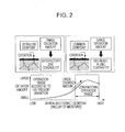
- Fig. 2 is a schematic diagram illustrating the relationship between the surface oxidation amounts of the zinc coatability-deteriorating elements and the dewpoint of the furnace atmospheric gas obtained from the results of the experiments and investigations conducted by the present inventors.
- surface oxidation amount tends to be large, and the degree of surface concentration of the zinc coatability-deteriorating elements tends to increase with an increase in the annealing temperature.
- the present inventors diligently conducted investigations in order to solve the problems described above and has completed the present invention whose subject matter is as follows.
- the present invention is premised on a facility including a continuous annealing furnace, a snout 4, and a galvanization bath 5.
- the furnace is divided into three zones, i.e., a heating zone 1 for heating a steel strip S, which is a strip-shaped steel sheet that is passed through the furnace, a soaking zone 2 for soaking the heated steel strip, and a cooling zone 3 for cooling the soaked steel strip, which are arranged in this order from the upstream side of a transport path.
- the bath is directly connected to the furnace through the snout, which is a closed space through which the steel strip is directly fed into the galvanization bath from the furnace.
- seal rolls 9 provided at pivotal points between the cooling zone 3 and the snout 4 in order to prevent the atmospheric gases of the different treatment sections from mixing with each other, and there are seal rolls 10 provided at the entrance of the heating zone 1 in order to prevent outer air from entering the furnace.
- a heater is provided in a part on the downstream side of the cooling zone 3 in order to perform an over-aging treatment. Such a premise is within a range of a well-known technique.
- the present invention is a facility including: (i) a dewpoint meter 6 and a suction port 7 and a spray port 8 of the furnace gas provided in at least one of the three zones (two zones which are the heating zone 1 and the soaking zone 2 in the present example); (ii) a refiner 11, which is a moisture removing device provided outside the furnace; (iii) gas cyclic paths 12 and 13, which connect the suction ports and the spray ports to the refiner 11, separately formed for the respective connected zones; (iv) and a dewpoint meter 6 and a humidification device 14 for humidifying the inside of the snout 4 provided in the snout 4.
- the refiner 11 functions so that, for each of the gas cyclic paths, a measured value of the dewpoint meter in the connected zone is equal to a target dewpoint, and the humidification device 14 functions so that a measured value of the dewpoint meter 6 in the snout 4 is equal to a target dewpoint for the snout 4.
- a pair of a suction port 7 and a spray port 8 is provided in each of the heating zone 1 and the soaking zone 2 in Fig. 1 . Because it is easier to control the dewpoint when a plural pairs is provided, however, two or more pairs of suction ports 7 and spray ports 8 may be provided in each zone, and the number of pairs is appropriately determined in order to achieve the target dewpoint.
- the gas cyclic paths 12 and 13, which are connected to different zones, are independent of each other and do not join together in the refiner 11.
- the refiner 11 functions, for each of the gas cyclic paths, to remove moisture in the gas in the gas cyclic path in order to control the dewpoint measured by the dewpoint meter of the zone to which the gas cyclic path is connected to be equal to a target dewpoint.
- the humidification device 14 functions so that humidification is performed by feeding moisture in the snout in order to control a dewpoint measured by the dewpoint meter in the snout to be equal to a target dewpoint, which is higher than that of the zone in the furnace.
- some of the gas from the zones of the furnace is suctioned and is sprayed back to the same zones after removing moisture, and humidification in the snout is performing using a humidification device. Accordingly, it is possible to stably control the dewpoint in the furnace to be low, i.e., -50°C or lower, and it is also possible to separately control the dewpoint in the furnace and the dewpoint in the snout. Thereby it is possible to stably achieve high quality and high zinc coatability for a galvanized steel sheet.
- the dewpoint meter 6, the suction port 7, and the spray port 8 may be provided in at least one of the three zones of the furnace. However, it is preferable to provided these devices in the soaking zone 2.
- the soaking zone 2 is a zone in which surface concentration of Si and Mn likely to occur due to higher furnace temperature than in the other zones. Accordingly, it is suitable to control the dewpoint to be low by preferentially placing the dewpoint meter, the suction port, and the spray port in this zone in order to stably achieve high zinc coatability.
- the facility further includes a suction port 7 and a drawing port 8 for the gas in the snout provided in the snout 4, and a gas cyclic path 15 between the refiner 11 and the snout formed by connecting these ports to the refiner 11.
- the refiner 11 also functions along with the humidification device 14 so that a dewpoint measured by the dewpoint meter in the snout is equal to a target dewpoint for the snout.
- the target dewpoint in the furnace is set to be -50°C or lower in order to suppress surface concentration of Si and Mn.
- the facility according to the present invention achieves such control for a low dewpoint, and it becomes possible to effectively prevent surface concentration of Si and Mn and stably achieve high zinc coatability.
- the dewpoint is -80°C or higher.
- the target dewpoint in the snout is -35°C or higher in order to effectively prevent vaporized zinc from attaching to a steel strip in the snout.
- the target dewpoint is -10°C or lower because, in the case where the dewpoint is excessively high, a zinc oxide film is formed on the bath surface, which is disadvantageous in that the film attaches to a steel strip.
- refiners having strong dehumidification capability such as desiccant-type ones which continuously perform dehumidification using, for example, calcium oxide, zeolite, silica gel, calcium chloride, or the like and compressor-type ones, which use, for example, substitute chlorofluorocarbon, are preferably used.
Landscapes
- Chemical & Material Sciences (AREA)
- Engineering & Computer Science (AREA)
- Mechanical Engineering (AREA)
- Materials Engineering (AREA)
- Metallurgy (AREA)
- Organic Chemistry (AREA)
- Chemical Kinetics & Catalysis (AREA)
- Physics & Mathematics (AREA)
- Thermal Sciences (AREA)
- Crystallography & Structural Chemistry (AREA)
- Coating With Molten Metal (AREA)
- Heat Treatment Of Strip Materials And Filament Materials (AREA)
Abstract
Description
- The present invention relates to a facility and method for continuously manufacturing a hot-dip galvanized steel sheet.
- A facility for continuously manufacturing a hot-dip galvanized steel sheet is a facility in which galvanization is performed by continuously annealing a steel strip, which is a strip-shaped steel sheet, using a continuous annealing furnace and by subsequently feeding the annealed steel strip into a plating bath of zinc or zinc alloy directly through a snout on the exit side of the continuous annealing furnace. The continuous annealing furnace commonly includes a heating zone in which a steel sheet that is being transported through an airtight furnace is heated to a temperature of about 800°C to 1000°C in a high-temperature gas atmosphere and a cooling zone in which the heated steel sheet is cooled to a temperature of about 300°C to 600°C by spraying a low-temperature gas. There is also a continuous annealing furnace having a soaking zone, in which the heated steel strip is soaked, subsequent to the heating zone. There is also a continuous annealing furnace having a preheating zone, in which the steel strip which has not been heated is preheated, prior to the heating zone.
- Patent Literature 1 describes a bright annealing furnace, which is a facility having only a furnace without a snout, provided with a ventilation pipe which is placed at the boundary of an interior refractory and an exterior steel shell of the furnace wall. The gas inside the furnace is discharged to the outside of the furnace through the ventilation pipe, and a furnace gas circulation device, into which the discharged gas is suctioned in order to clean the gas by removing impurities in the gas and from which the cleaned gas is returned into the furnace, is additionally installed outside the furnace. Thereby, in particular, a seasoning time, or the time required to start up a new furnace at the beginning of its operation or to start up a repaired furnace when the furnace is resumed to operate, is significantly decreased.
-
Patent Literature 2 describes a technique using an apparatus for continuous annealing in a reducing atmosphere, which is an apparatus having only a furnace without a snout, for a metal strip. A refiner, which is a moisture removing device and is referred to as a refining device inPatent Literature 2, is utilized. Thereby, the cooling efficiency is increased by spraying the gas in a preheating zone, which provided prior to a heating zone, into a cooling zone, or the preheating efficiency is increased by conversely spraying the gas in the cooling zone into the preheating zone. -
- PTL 1: Japanese Unexamined Patent Application Publication No.
4-116127 - PTL 2: Japanese Unexamined Patent Application Publication No.
11-236623 - In the case of a facility for continuously manufacturing a galvanized steel sheet, it is necessary that a dewpoint is lowered by removing moisture in a continuous annealing furnace in order to increase zinc coatability, or adhesiveness of a galvanized or galvannealed film to the surface of a steel sheet. Accordingly, the dewpoint is conventionally controlled by suctioning the furnace gas from the cooling zone, removing the moisture from the gas by using a refiner, which is installed outside the furnace, and then returning the gas into the heating zone. With this method, however, it is difficult to stably achieve high zinc coatability. The reason for that will be described hereafter.
- Although it is known that adding Si, Mn, or the like is effective in order to increase the strength of a steel material, Si and Mn are zinc coatability-deteriorating elements. Accordingly, there are limits to the amounts of Si and Mn added to steel for a galvanized steel sheet.
Fig. 2 is a schematic diagram illustrating the relationship between the surface oxidation amounts of the zinc coatability-deteriorating elements and the dewpoint of the furnace atmospheric gas obtained from the results of the experiments and investigations conducted by the present inventors. In a common dewpoint range, in which the operation is conventionally performed, surface oxidation amount tends to be large, and the degree of surface concentration of the zinc coatability-deteriorating elements tends to increase with an increase in the annealing temperature. However, as illustrated inFig. 2 , since surface concentration of the zinc coatability-deteriorating elements is suppressed by decreasing the dewpoint in the furnace, it is possible to achieve satisfactory zinc coatability even when annealing is performed at a high temperature. That is to say, in the common dewpoint range, it is difficult to suppress surface concentration of the zinc coatability-deteriorating elements and, hence, zinc coatability deteriorates. For example, the relationship between the degree of surface concentration of each element of a steel sheet containing 1.5 mass% of Si or 2.0 mass% of Mn in steel and a dewpoint in the furnace was investigated. It was clarified that there was a significant decrease in the degree of surface concentration of Mn at the dewpoint of -45°C or lower and that there was a significant decrease in the degree of surface concentration of Si at the dewpoint of -50°C or lower. That is, it was necessary to control the dewpoint in the furnace to be -50°C or lower in order to stably achieve high zinc coatability by suppressing surface concentration of Si and Mn. However, the dewpoint can only be lowered to about -40°C using the method described above in which the gas in the furnace is suctioned from the cooling zone so as to remove moisture using a refiner provided outside the furnace and then returned to the heating zone. Therefore, it was difficult to stably achieve high zinc coatability. - On the other hand, in the case of a continuous galvanization facility which has a galvanization bath, there was a problem related to the dewpoint of an atmospheric gas in a snout. That is, in the case where the dewpoint in the snout is significantly lowered along with a lowered dewpoint in the furnace, since molten zinc is vaporized, the vaporized zinc attaches to a steel strip, which results in poor product quality.
- As described above, in the case of a conventional continuous facility for manufacturing a galvanized steel sheet, it was difficult to stably achieve satisfactory zinc coatability because it is not possible to control the dewpoint of a continuous annealing furnace to be -50°C or lower. Furthermore, the product quality was degraded as a result of molten zinc vaporized in the snout attaching to a steel strip in the case where the dewpoint in the furnace is lowered. Accordingly, there was a problem in that satisfactory galvanized product quality and zinc coatability are not stably achieved.
- The present inventors diligently conducted investigations in order to solve the problems described above and has completed the present invention whose subject matter is as follows.
- (1) A facility for continuously manufacturing a galvanized steel sheet, which includes a continuous annealing furnace divided into three zones including a heating zone that heats a steel strip which is a strip-shaped steel sheet to be passed through the furnace, a soaking zone that soaks the heated steel strip, and a cooling zone that cools the soaked steel strip, which are arranged in this order from an upstream side of a transport path; a galvanization bath; a snout that directly connects the furnace to the galvanization bath therethrough, the snout being a closed space through which the steel strip is directly fed into the galvanization bath from the furnace; a first dewpoint meter and a suction port and a spray port for a gas within the furnace that are provided in at least one of the three zones of the furnace; a gas cyclic path that connects the draft port and the suction port to a refiner, which is a moisture removing device provided outside the furnace, separately formed for each of the connected zones; and a second dewpoint meter and a humidification device, which humidifies an inside of the snout, that are provided in the snout. The refiner functions so that, for each of the gas cyclic paths, a first measured value of the first dewpoint meter in the connected zone is equal to a first target dewpoint; and the humidification device functions so that a second measured value of the second dewpoint meter in the snout is equal to a second target dewpoint for the snout.
- (2) The facility for continuously manufacturing a galvanized steel sheet according to item (1), which further includes a snout suction port and a snout spray port for a gas within the snout that are provided in the snout, and a snout gas cyclic path formed between the refiner and the snout by connecting the ports thereof to the refiner. The refiner functions along with the humidification device so that the second measured value of the second dewpoint meter in the snout is equal to the second target dewpoint for the snout.
- (3) A method for continuously manufacturing a galvanized steel sheet using the facility for continuously manufacturing a galvanized steel sheet according to item (1) or (2), in which a galvanization operation is performed while setting the first target dewpoint of the furnace to-50°C or lower and -80°C or higher and the second target dewpoint of the snout to -35°C or higher and -10°C or lower.
- According to the present invention, it is possible to stably achieve high galvanized product quality and high zinc coatability.
-
- [
Fig. 1] Fig. 1 is a schematic diagram illustrating an embodiment of the present invention. - [
Fig. 2] Fig. 2 is a schematic diagram illustrating the relationship between the surface oxidation amounts of zinc coatability-deteriorating elements and the dewpoint of a furnace atmospheric gas. - [
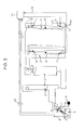
Fig. 3] Fig. 3 is a schematic diagram illustrating an embodiment of the present invention, which is different from the one illustrated inFig. 1 . - As illustrated in, for example,
Fig. 1 , the present invention is premised on a facility including a continuous annealing furnace, a snout 4, and a galvanization bath 5. The furnace is divided into three zones, i.e., a heating zone 1 for heating a steel strip S, which is a strip-shaped steel sheet that is passed through the furnace, asoaking zone 2 for soaking the heated steel strip, and a cooling zone 3 for cooling the soaked steel strip, which are arranged in this order from the upstream side of a transport path. The bath is directly connected to the furnace through the snout, which is a closed space through which the steel strip is directly fed into the galvanization bath from the furnace. There areseal rolls 9 provided at pivotal points between the cooling zone 3 and the snout 4 in order to prevent the atmospheric gases of the different treatment sections from mixing with each other, and there areseal rolls 10 provided at the entrance of the heating zone 1 in order to prevent outer air from entering the furnace. There is also a case where a heater is provided in a part on the downstream side of the cooling zone 3 in order to perform an over-aging treatment. Such a premise is within a range of a well-known technique. - Under such a premise, the present invention is a facility including: (i) a
dewpoint meter 6 and asuction port 7 and aspray port 8 of the furnace gas provided in at least one of the three zones (two zones which are the heating zone 1 and thesoaking zone 2 in the present example); (ii) arefiner 11, which is a moisture removing device provided outside the furnace; (iii) gascyclic paths refiner 11, separately formed for the respective connected zones; (iv) and adewpoint meter 6 and ahumidification device 14 for humidifying the inside of the snout 4 provided in the snout 4. In the facility, therefiner 11 functions so that, for each of the gas cyclic paths, a measured value of the dewpoint meter in the connected zone is equal to a target dewpoint, and thehumidification device 14 functions so that a measured value of thedewpoint meter 6 in the snout 4 is equal to a target dewpoint for the snout 4. - Here, a pair of a
suction port 7 and aspray port 8 is provided in each of the heating zone 1 and thesoaking zone 2 inFig. 1 . Because it is easier to control the dewpoint when a plural pairs is provided, however, two or more pairs ofsuction ports 7 andspray ports 8 may be provided in each zone, and the number of pairs is appropriately determined in order to achieve the target dewpoint. - The gas
cyclic paths refiner 11. Therefiner 11 functions, for each of the gas cyclic paths, to remove moisture in the gas in the gas cyclic path in order to control the dewpoint measured by the dewpoint meter of the zone to which the gas cyclic path is connected to be equal to a target dewpoint. On the other hand, thehumidification device 14 functions so that humidification is performed by feeding moisture in the snout in order to control a dewpoint measured by the dewpoint meter in the snout to be equal to a target dewpoint, which is higher than that of the zone in the furnace. - As described above, some of the gas from the zones of the furnace is suctioned and is sprayed back to the same zones after removing moisture, and humidification in the snout is performing using a humidification device. Accordingly, it is possible to stably control the dewpoint in the furnace to be low, i.e., -50°C or lower, and it is also possible to separately control the dewpoint in the furnace and the dewpoint in the snout. Thereby it is possible to stably achieve high quality and high zinc coatability for a galvanized steel sheet.
- The
dewpoint meter 6, thesuction port 7, and thespray port 8 may be provided in at least one of the three zones of the furnace. However, it is preferable to provided these devices in the soakingzone 2. The soakingzone 2 is a zone in which surface concentration of Si and Mn likely to occur due to higher furnace temperature than in the other zones. Accordingly, it is suitable to control the dewpoint to be low by preferentially placing the dewpoint meter, the suction port, and the spray port in this zone in order to stably achieve high zinc coatability. Here, it is needless to say that it is most preferable to provide these devices in all of the three zones. - In the case of the example illustrated in
Fig. 3 , in addition to the example illustrated inFig. 1 , the facility further includes asuction port 7 and a drawingport 8 for the gas in the snout provided in the snout 4, and a gascyclic path 15 between therefiner 11 and the snout formed by connecting these ports to therefiner 11. In the facility, therefiner 11 also functions along with thehumidification device 14 so that a dewpoint measured by the dewpoint meter in the snout is equal to a target dewpoint for the snout. Using this facility, it is possible to control the dewpoint in the snout with increased accuracy. Accordingly, it is possible to prevent the attachment of vaporized zinc in the snout more effectively, which results in high galvanized product quality achieved with significantly increased stability. - In a galvanization operation using the facility according to the present invention, it is preferable that, as described above, the target dewpoint in the furnace is set to be -50°C or lower in order to suppress surface concentration of Si and Mn. Using the facility according to the present invention achieves such control for a low dewpoint, and it becomes possible to effectively prevent surface concentration of Si and Mn and stably achieve high zinc coatability. Here, because there is a significant increase in cost in order to lower the dewpoint to lower than -80°C, it is preferable that the dewpoint is -80°C or higher. On the other hand, it is possible to control the dewpoint in the snout independently of the dewpoint in the furnace by using the facility according to the present invention. It is preferable that the target dewpoint in the snout is -35°C or higher in order to effectively prevent vaporized zinc from attaching to a steel strip in the snout. However, it is preferable that the target dewpoint is -10°C or lower because, in the case where the dewpoint is excessively high, a zinc oxide film is formed on the bath surface, which is disadvantageous in that the film attaches to a steel strip.
- Here, among examples of the refiner, refiners having strong dehumidification capability such as desiccant-type ones which continuously perform dehumidification using, for example, calcium oxide, zeolite, silica gel, calcium chloride, or the like and compressor-type ones, which use, for example, substitute chlorofluorocarbon, are preferably used.
- An EXAMPLE in which the present invention was applied to a continuous line for manufacturing a galvanized steel sheet in the embodiment similar to the example illustrated in
Fig. 3 will be described. In this line, conventionally, a dewpoint in the furnace was controlled using a method in which furnace gas was suctioned from a cooling zone, moisture was removed using a refiner provided outside of the furnace, and then the gas was returned to a heating zone. However, the lower limit of achievable dewpoint in the furnace was about -40°C, and the dewpoint was not controlled in the snout. Therefore, in the operation of the galvanization of a high-strength steel sheet to which Si and Mn are added, the control was not satisfactorily effective for suppressing bare spots and poor surface quality. In contrast, in the case of EXAMPLE, it was possible to stably control the dewpoint in the soaking zone to be -50°C or lower and -80°C or higher, and it was possible to stably control the dewpoint in the snout to be -35°C or higher and -10°C or lower. As a result, the occurrence frequency of bare spots was significantly decreased to 10, and the occurrence frequency of poor surface quality was significantly decreased to 20 when the conventional occurrence frequency of bare spots was defined as 100, which indicates a significant effect of the present invention. -
- 1
- heating zone
- 2
- soaking zone
- 3
- cooling zone
- 4
- snout
- 5
- galvanization bath
- 6
- dewpoint meter
- 7
- suction port
- 8
- spray port
- 9, 10
- seal roll
- 11
- refiner (moisture removing device)
- 12, 13, 15
- gas cyclic path
- 14
- humidification device
- S
- steel strip
Claims (3)
- A facility for continuously manufacturing a galvanized steel sheet, comprising:a continuous annealing furnace divided into three zones including a heating zone that heats a steel strip which is a strip-shaped steel sheet to be passed through the furnace, a soaking zone that soaks the heated steel strip, and a cooling zone that cools the soaked steel strip, which are arranged in this order from an upstream side of a transport path;a galvanization bath;a snout that directly connects the furnace to the galvanization bath therethrough, the snout being a closed space through which the steel strip is directly fed into the galvanization bath from the furnace;a first dewpoint meter and a suction port and a spray port for a gas within the furnace that are provided in at least one of the three zones of the furnace;a gas cyclic path that connects the suction port and the spray port to a refiner, which is a moisture removing device provided outside the furnace, separately formed for each of the connected zones; anda second dewpoint meter and a humidification device, which humidifies an inside of the snout, that are provided in the snout,wherein:the refiner functions so that, for each of the gas cyclic paths, a first measured value of the first dewpoint meter in the connected zone is equal to a first target dewpoint; andthe humidification device functions so that a second measured value of the second dewpoint meter in the snout is equal to a second target dewpoint for the snout.
- The facility for continuously manufacturing a galvanized steel sheet according to Claim 1, further comprising a snout suction port and a snout spray port for a gas within the snout that are provided in the snout, and a snout gas cyclic path formed between the refiner and the snout by connecting the ports thereof to the refiner,
wherein the refiner functions along with the humidification device so that the second measured value of the second dewpoint meter in the snout is equal to the second target dewpoint for the snout. - A method for continuously manufacturing a galvanized steel sheet using the facility for continuously manufacturing a galvanized steel sheet according to Claim 1 or 2, wherein a galvanization operation is performed while setting the first target dewpoint of the furnace to -50°C or lower and -80°C or higher and the second target dewpoint for the snout to -35°C or higher and -10°C or lower.
Applications Claiming Priority (1)
| Application Number | Priority Date | Filing Date | Title |
|---|---|---|---|
| PCT/JP2012/007778 WO2014087452A1 (en) | 2012-12-04 | 2012-12-04 | Facility and method for manufacturing continuous hot-dip zinc-coated steel sheet |
Publications (2)
| Publication Number | Publication Date |
|---|---|
| EP2927342A1 true EP2927342A1 (en) | 2015-10-07 |
| EP2927342A4 EP2927342A4 (en) | 2016-01-06 |
Family
ID=50882908
Family Applications (1)
| Application Number | Title | Priority Date | Filing Date |
|---|---|---|---|
| EP12889434.2A Withdrawn EP2927342A4 (en) | 2012-12-04 | 2012-12-04 | Facility and method for manufacturing continuous hot-dip zinc-coated steel sheet |
Country Status (6)
| Country | Link |
|---|---|
| US (1) | US10233526B2 (en) |
| EP (1) | EP2927342A4 (en) |
| KR (1) | KR20150084051A (en) |
| CN (1) | CN104838034A (en) |
| IN (1) | IN2015DN03981A (en) |
| WO (1) | WO2014087452A1 (en) |
Cited By (2)
| Publication number | Priority date | Publication date | Assignee | Title |
|---|---|---|---|---|
| EP3168321A4 (en) * | 2014-07-07 | 2017-05-31 | JFE Steel Corporation | Production method for alloyed hot-dip-galvanized steel sheet |
| US12618132B2 (en) | 2021-07-14 | 2026-05-05 | Jfe Steel Corporation | Method for manufacturing hot-dip galvanized steel sheet |
Families Citing this family (5)
| Publication number | Priority date | Publication date | Assignee | Title |
|---|---|---|---|---|
| JP6008007B2 (en) * | 2015-03-23 | 2016-10-19 | Jfeスチール株式会社 | Continuous hot dip galvanizing apparatus and method for producing hot dip galvanized steel sheet |
| JP2018044183A (en) * | 2016-09-12 | 2018-03-22 | 株式会社神戸製鋼所 | Production metho of plated steel sheet |
| CN108842121A (en) * | 2018-08-25 | 2018-11-20 | 宝钢湛江钢铁有限公司 | A kind of strip continuous hot-dipping Zn system |
| CN115287567A (en) * | 2022-08-04 | 2022-11-04 | 江阴市华达机械科技有限公司 | Stove nose humidification system |
| CN117051344A (en) * | 2023-08-02 | 2023-11-14 | 山东宇信铸业有限公司 | A hot-dip galvanizing method for large and ultra-thick cast iron guardrails |
Family Cites Families (26)
| Publication number | Priority date | Publication date | Assignee | Title |
|---|---|---|---|---|
| US3778221A (en) * | 1969-02-26 | 1973-12-11 | Allegheny Ludlum Ind Inc | Annealing furnace and method for its operation |
| US4415382A (en) * | 1981-10-13 | 1983-11-15 | Inland Steel Company | Continuous annealing apparatus and method |
| JPS6043476A (en) * | 1983-08-17 | 1985-03-08 | Nippon Steel Corp | Continuous aluminizing method |
| US4557953A (en) * | 1984-07-30 | 1985-12-10 | Armco Inc. | Process for controlling snout zinc vapor in a hot dip zinc based coating on a ferrous base metal strip |
| FR2664617B1 (en) * | 1990-07-16 | 1993-08-06 | Lorraine Laminage | PROCESS FOR COATING ALUMINUM BY HOT TEMPERING OF A STEEL STRIP AND STEEL STRIP OBTAINED BY THIS PROCESS. |
| JP2567140B2 (en) | 1990-09-04 | 1996-12-25 | 日本冶金工業株式会社 | Bright annealing furnace |
| US5447754A (en) * | 1994-04-19 | 1995-09-05 | Armco Inc. | Aluminized steel alloys containing chromium and method for producing same |
| US5827618A (en) * | 1995-03-28 | 1998-10-27 | Nippon Steel Corporation | Rust-proofing steel sheet for fuel tanks and production method thereof |
| JPH09324210A (en) | 1996-06-07 | 1997-12-16 | Kawasaki Steel Corp | Manufacturing method and manufacturing facility for hot-dip galvanized steel sheet |
| JPH10176225A (en) | 1996-12-13 | 1998-06-30 | Daido Steel Co Ltd | Continuous annealing furnace for metal strip |
| US6093452A (en) * | 1997-02-25 | 2000-07-25 | Nkk Corporation | Continuous hot-dip coating method and apparatus therefor |
| JP4156065B2 (en) | 1998-02-24 | 2008-09-24 | 日新製鋼株式会社 | Continuous reducing atmosphere annealing apparatus and method for metal strip |
| FR2782326B1 (en) * | 1998-08-13 | 2000-09-15 | Air Liquide | METHOD FOR GALVANIZING A METAL STRIP |
| FR2807069B1 (en) * | 2000-03-29 | 2002-10-11 | Usinor | COATED FERRITIC STAINLESS STEEL SHEET FOR USE IN THE EXHAUST SYSTEM OF A MOTOR VEHICLE |
| US6635313B2 (en) * | 2001-11-15 | 2003-10-21 | Isg Technologies, Inc. | Method for coating a steel alloy |
| US6902829B2 (en) * | 2001-11-15 | 2005-06-07 | Isg Technologies Inc. | Coated steel alloy product |
| JP3933047B2 (en) * | 2002-03-06 | 2007-06-20 | Jfeスチール株式会社 | Continuous molten metal plating method and apparatus |
| JP4192051B2 (en) * | 2003-08-19 | 2008-12-03 | 新日本製鐵株式会社 | Manufacturing method and equipment for high-strength galvannealed steel sheet |
| CN101287854B (en) * | 2005-10-14 | 2011-04-20 | 新日本制铁株式会社 | Continuous annealing hot-dip coating method and continuous annealing hot-dip coating device for Si-containing steel sheet |
| KR101178614B1 (en) * | 2006-10-13 | 2012-08-30 | 신닛뽄세이테쯔 카부시키카이샤 | Apparatus and process for producing steel sheet plated by hot dipping with alloyed zinc |
| JP2012017495A (en) * | 2010-07-07 | 2012-01-26 | Jfe Steel Corp | Method for continuously annealing steel sheet and method for producing hot-dip galvannealed steel sheet |
| JP5071551B2 (en) | 2010-12-17 | 2012-11-14 | Jfeスチール株式会社 | Continuous annealing method for steel strip, hot dip galvanizing method |
| JP5505430B2 (en) * | 2012-01-17 | 2014-05-28 | Jfeスチール株式会社 | Continuous annealing furnace and continuous annealing method for steel strip |
| KR101564870B1 (en) * | 2012-04-09 | 2015-10-30 | 제이에프이 스틸 가부시키가이샤 | Method for reducing dew point of atmosphere gas in annealing furnace, apparatus for the same and method for producing cold-rolled and annealed steel sheet |
| CN104220610B (en) * | 2012-04-09 | 2017-08-08 | 杰富意钢铁株式会社 | The manufacture method of the dew point reduction method of atmosphere gas, its device and cold rolled annealed steel plate in annealing furnace |
| JP5505461B2 (en) * | 2012-05-24 | 2014-05-28 | Jfeスチール株式会社 | Continuous annealing furnace for steel strip, continuous annealing method for steel strip, continuous hot dip galvanizing equipment and method for manufacturing hot dip galvanized steel strip |
-
2012
- 2012-12-04 IN IN3981DEN2015 patent/IN2015DN03981A/en unknown
- 2012-12-04 KR KR1020157015564A patent/KR20150084051A/en not_active Ceased
- 2012-12-04 US US14/649,408 patent/US10233526B2/en active Active
- 2012-12-04 WO PCT/JP2012/007778 patent/WO2014087452A1/en not_active Ceased
- 2012-12-04 EP EP12889434.2A patent/EP2927342A4/en not_active Withdrawn
- 2012-12-04 CN CN201280077492.3A patent/CN104838034A/en active Pending
Cited By (2)
| Publication number | Priority date | Publication date | Assignee | Title |
|---|---|---|---|---|
| EP3168321A4 (en) * | 2014-07-07 | 2017-05-31 | JFE Steel Corporation | Production method for alloyed hot-dip-galvanized steel sheet |
| US12618132B2 (en) | 2021-07-14 | 2026-05-05 | Jfe Steel Corporation | Method for manufacturing hot-dip galvanized steel sheet |
Also Published As
| Publication number | Publication date |
|---|---|
| KR20150084051A (en) | 2015-07-21 |
| IN2015DN03981A (en) | 2015-10-02 |
| WO2014087452A1 (en) | 2014-06-12 |
| US10233526B2 (en) | 2019-03-19 |
| EP2927342A4 (en) | 2016-01-06 |
| CN104838034A (en) | 2015-08-12 |
| US20150315691A1 (en) | 2015-11-05 |
Similar Documents
| Publication | Publication Date | Title |
|---|---|---|
| US10233526B2 (en) | Facility having a continuous annealing furnace and a galvanization bath and method for continuously manufacturing hot-dip galvanized steel sheet | |
| CN104379776B (en) | The manufacture device of the continuous annealing method of steel band, the continuous annealer of steel band, the manufacture method of molten zinc plating steel band and molten zinc plating steel band | |
| US9388484B2 (en) | Continuous annealing furnace for annealing steel strip, method for continuously annealing steel strip, continuous hot-dip galvanizing facility, and method for manufacturing hot-dip galvanized steel strip | |
| WO2012081719A1 (en) | Method for continuously annealing steel strip and hot-dip galvanization method | |
| WO2013108624A1 (en) | Steel strip continuous annealing furnace and continuous annealing method | |
| CN104204240B (en) | Continous way dip galvanizing equipment | |
| JP6052464B2 (en) | Reduction furnace dew point control method and reduction furnace | |
| CN101287854A (en) | Method and apparatus for continuous annealing hot dip plating of Si-containing steel sheet | |
| KR101862206B1 (en) | Method of producing galvannealed steel sheet | |
| JP5834775B2 (en) | Manufacturing equipment and manufacturing method for continuous hot-dip galvanized steel sheet | |
| EP3730662A1 (en) | Method for producing hot-dip galvanized steel sheet and continuous hot-dip galvanizing apparatus | |
| CN107429374A (en) | The manufacture method of continuous hot-dipping galvanizing device and hot-dip galvanized steel sheet | |
| EP3369836A1 (en) | Method for manufacturing hot-dip galvanized steel sheet | |
| EP2837700B1 (en) | Method for lowering dew point of atmosphere gas within annealing furnace, device thereof, and method for producing cold-rolled annealed steel sheet | |
| CN104379777B (en) | The continuous annealing method of steel band and the manufacture method of hot-galvanized steel band | |
| EP2837699A1 (en) | Device and method for reducing dew point of ambient gas in annealing furnace, and method for producing cold-rolled annealed steel plate | |
| JP7334860B2 (en) | Dew point control method for continuous annealing furnace, continuous annealing method for steel plate, method for manufacturing steel plate, continuous annealing furnace, continuous hot dip galvanizing equipment, and hot dip galvannealing equipment | |
| JP2003342645A (en) | In-line annealing furnace for continuous hot dip galvanizing | |
| CN117616146A (en) | Manufacturing method of hot-dip galvanized steel sheet | |
| CN202064002U (en) | Bright processing system of stainless steel belt | |
| KR100678353B1 (en) | Method and apparatus for hot-dip galvanizing hot rolled steel strip | |
| KR102498652B1 (en) | Method of treatment of a running ferrous alloy sheet and treatment line for its implementation | |
| JP2002155318A (en) | Switchable continuous heat treatment equipment | |
| TH141117A (en) | Method of continuous annealing of steel strips and manufacturing methods of hot-dip galvanized steel strips. |
Legal Events
| Date | Code | Title | Description |
|---|---|---|---|
| PUAI | Public reference made under article 153(3) epc to a published international application that has entered the european phase |
Free format text: ORIGINAL CODE: 0009012 |
|
| 17P | Request for examination filed |
Effective date: 20150527 |
|
| AK | Designated contracting states |
Kind code of ref document: A1 Designated state(s): AL AT BE BG CH CY CZ DE DK EE ES FI FR GB GR HR HU IE IS IT LI LT LU LV MC MK MT NL NO PL PT RO RS SE SI SK SM TR |
|
| AX | Request for extension of the european patent |
Extension state: BA ME |
|
| RA4 | Supplementary search report drawn up and despatched (corrected) |
Effective date: 20151209 |
|
| RIC1 | Information provided on ipc code assigned before grant |
Ipc: C23C 2/06 20060101ALI20151203BHEP Ipc: C23C 2/02 20060101AFI20151203BHEP Ipc: C21D 1/76 20060101ALI20151203BHEP Ipc: C21D 9/56 20060101ALI20151203BHEP |
|
| DAX | Request for extension of the european patent (deleted) | ||
| STAA | Information on the status of an ep patent application or granted ep patent |
Free format text: STATUS: THE APPLICATION IS DEEMED TO BE WITHDRAWN |
|
| 18D | Application deemed to be withdrawn |
Effective date: 20160716 |