EP2927147A1 - Support structure for supporting a big-bag - Google Patents
Support structure for supporting a big-bag Download PDFInfo
- Publication number
- EP2927147A1 EP2927147A1 EP14163645.6A EP14163645A EP2927147A1 EP 2927147 A1 EP2927147 A1 EP 2927147A1 EP 14163645 A EP14163645 A EP 14163645A EP 2927147 A1 EP2927147 A1 EP 2927147A1
- Authority
- EP
- European Patent Office
- Prior art keywords
- support structure
- frame
- uprights
- distance
- shaped
- Prior art date
- Legal status (The legal status is an assumption and is not a legal conclusion. Google has not performed a legal analysis and makes no representation as to the accuracy of the status listed.)
- Granted
Links
Images


Classifications
-
- B—PERFORMING OPERATIONS; TRANSPORTING
- B65—CONVEYING; PACKING; STORING; HANDLING THIN OR FILAMENTARY MATERIAL
- B65D—CONTAINERS FOR STORAGE OR TRANSPORT OF ARTICLES OR MATERIALS, e.g. BAGS, BARRELS, BOTTLES, BOXES, CANS, CARTONS, CRATES, DRUMS, JARS, TANKS, HOPPERS, FORWARDING CONTAINERS; ACCESSORIES, CLOSURES, OR FITTINGS THEREFOR; PACKAGING ELEMENTS; PACKAGES
- B65D19/00—Pallets or like platforms, with or without side walls, for supporting loads to be lifted or lowered
- B65D19/38—Details or accessories
- B65D19/385—Frames, corner posts or pallet converters, e.g. for facilitating stacking of charged pallets
Definitions
- the invention relates to a support structure for supporting a big-bag.
- Big-bags are typically used for storing and transporting bulk material, like sand, gravel and forage.
- the size of such big-bags is usually one cubic meter and sometimes two cubic meter having a foot print of about one square meter.
- the big-bags are provided with loops at the top edge of the big-bag, such that the big-bags can be lifted.
- attaching the loops to a hoisting device is time consuming, so often, the big-bags are placed on a pallet, such that the big-bags can be lifted by a forklift.
- big-bags cannot be stacked.
- the top surface of the big-bag is formed by the bulk material, there is no level surface available onto which a next big-bag could be placed.
- the support strenght has to be provided mainly by the big-bag material, as the bulk material typically has no internal consistency, which could contribute to the support strenght. So, if a second big-bag would be stacked on top of a first big-bag, the material of the first big-bag needs to be twice as strong to also support the second big-bag.
- support structures provide a second floor over the floor on which a first row of big-bags is provided.
- GB 2187934 discloses a support structure for storing goods.
- the structure has frame work, which can be placed on a floor over goods and provides a second floor level for storing additional goods.
- the frame work has horizontal rails connecting a front assembly with a rear assembly.
- the big-bags are placed on a pallet to form goods and the goods (i.e. the pallets with the big-bags) are handled by a forklift. If a pallet is not correctly aligned with the support structure, it may frontally hit the uprights of the support structure or the ends of the horizontal rails at the base of the support frame running from the front to the back of the support frame. In such a case the pallet with the big-bag will need to be retracted and repositioned for a new attempt. It requires skill and good judgement to place the goods with the goods with only few attempts.
- a support structure for supporting a big-bag according to the invention which support structure comprises:
- the legs of the U-shaped based frame function as guide rails to center the goods with respect to the support structure.
- the support structure is chosen such that it is tall enough such that the top frame is not in the way when loading or unloading the goods.
- the distance between the at least two first uprights is larger than the distance between the legs of the U-shaped base frame at the base part of the base frame.
- the advantage of this embodiment is that the chances that the at least two first uprights are hit by goods when loading are lowered.
- the at least two second uprights are arranged at a distance of the corners that connect the legs to the base of the U-shaped base frame and the distance between the at least two first uprights is larger than the maximal distance occupied by the at least two second uprights.
- the second uprights are arranged at a distance from the corners, which makes that the legs of the U-shaped base frame from the one support structure can be positioned over the legs of the U-shaped base frame from the other support structure. Because the first uprigths are far enough apart, i.e. their distance is larger than the maximum distance occupied by the second uprights, they can be slid passed the second uprights.
- a support beam is arranged between the free ends of the U-shaped top frame.
- the support beam provides additional strength to the support structure and provides additional locations for supporting goods on top of the support structure.
- the top frame can be further strengthend by additional support beams extending in the plane of the top frame.
- an additional support beam connects the base of the U-shaped top frame and the support beam.
- the additional support beam isaligned with the direction in which goods a moved above the support structure for placement onto the support structure. Therefore, there the chances that the additional support beam is hit when loading (or unloading) are miminized.
- the at least two first uprights are arranged to the support beam at a distance from the free ends of the U-shaped top frame.
- the direction of the legs of the U-shaped top frame does not depend on the position of the at least two first uprights. This provides freedom to produce a stronger support structure.
- the two legs of the U-shaped top frame are parallel.
- the support structure comprises distance holders arranged to suppor the stupport structre when nested.
- the base of the top frame of a second support structure is at a distance from the base of a top frame of a first support structure, that is underneath the second support structure. Therefore it is easier to lift the second support structure with a forklift by introducing the fork in the space between the base of the top frame of the second support structure and the base of the top frame of the first support structure.
- Yet another embodiment of the support structure according to the invention further comprises a number of cross linked pull bars arranged between adjacent uprights, when seen along the path of the U-shaped base frame.
- the cross linked pull bars arranged between an upright extending from a free end of the U-shaped base frame and an upright extending from the corner of the U-shaped base frame, are arranged on the inside of the upright extending from the free end and are arranged on the outside of the upright extending from the corner.
- the cross linked pull bars will converge somewhat from the first uprights to the second uprights. This will facilitate positioning objects, like a big-bag, within the support structure.
- Figure 1 shows a perspective view of an embodiment of a support structure 1 according to the invention.
- This support structure 1 has U-shaped base frame 2, 3, 4 with two legs 2, 4 and a base part 3 connecting the legs 2, 4.
- the support structure 1 furthermore has a U-shaped top frame 5, 6, 7 with legs 5, 7 and base part 6.
- the free ends of the legs 5, 7 are connected by a support beam 8.
- Two first uprights 9, 10 extend from the free end of legs 2, 4 towards the support beam 8 next to the free ends of the legs 5, 7.
- Two second uprights 11, 12 are arranged at a distance from the corners 13, 14 of the U-shaped base frame 2, 3, 4 and extend upwards to the base 6 of the U-shaped top frame 5, 6, 7.
- the base part 3 of the U-shaped base frame and the base part 6 of the U-shaped top frame are parallel.
- Both the U-shaped base frame and the U-shaped top frame as well as the two first uprights and the two second uprights are made from straight pipes and all have a rectangular cross section with equal diamensions.
- the legs 2,4 of the base frame are not parallel; the further the distance from the base part 3, the larger the distance between the legs 2,4.
- the first uprights 9,10 are welded onto the free ends of the legs 2,4 of the base frame such that the first uprights 9,10 do not stand wider apart or less wide apart than the free ends of the legs 2,4 they are welded to. This and the fact that the distance between the legs 2,4 increases with increasing distance to the base part 3 of the base frame, makes that the distance between the first uprights is larger than the distance between the legs of the U-shaped base frame at the base part 3.
- cross linked pull bars 15, 16, 17 are arranged in three of the four vertical sides of the structure 1. As can be seen, the pull bars 15, 17 are arranged on the inside of the first uprights 9, 10 and on the outside of the second uprights 11, 12.
- FIG. 2 shows a perspective view of a number of nested support structures 1 according to the invention.
- each base frame of a support structure 1 rests on top of a base frame of an adjacent support structure 1.
- the second uprights 11, 12 are arranged at a distance from the corners 13, 14.
- the distance between the at least two first uprights is larger than the distance between the surfaces of the two second uprights facing away from each other.
- the distance between the surfaces of the two second uprights facing away from each other is equal to the maximal distance occupied by the at least two second uprights.
- Figure 3 shows an embodiment of a support structure 1 in use.
- the support structure 1 is positioned over a big-bag 20 filled with a bulk material and placed on a pallet 21 for easy handling by a forklift.
- a second pallet 22 is placed on which a second big-bag 23 filled with bulk material is arranged.
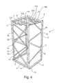
- the support structure 1 comprises a number of distance holders 101, 102, 103, 104. Two distance holders 101,102 are attached to a surface of a leg of U-shaped top frame, the two other distance holders 103,104 are attached to a surface of the other leg of U-shaped top frame. The surfaces to which the distance holders are attached face towards the U-shaped base frame.
- the support structure 1 also comprises two additional beams 110, 111 that run from the base part of the U-shaped top frame to the support beam 8.
- the two additional beams and the legs of the U-shaped top frame are parallel and run perpendicular to the base part of the Y-shaped top frame.
- the additional beams 110, 111 are made from straight pipes and have rectangular cross sections with equal dimensions as the pipes of the base frame.
Landscapes
- Engineering & Computer Science (AREA)
- Mechanical Engineering (AREA)
- Assembled Shelves (AREA)
- Pallets (AREA)
Abstract
- a U-shaped base frame (2, 3, 4) comprising two legs (2, 4) connected by a base part (3);
- a U-shaped top frame (5, 6, 7) comprising two legs (5, 7) connected by a base part (6);
- at least two first uprights (9, 10) arranged between the free ends of the U-shaped base frame (2, 3, 4) and the free ends of the U-shaped top frame (5, 6, 7),
- at least two second uprights (11, 12) arranged to the base part (3) of the U-shaped base frame (2, 3, 4) extending vertically to the base part (6) of the U-shaped top frame (5, 6, 7),
wherein the distance between the legs (2, 4) of the U-shaped base frame (2, 3, 4) increases with increasing distance to the base part (3) of the U-shaped base frame (2, 3, 4).
Description
- The invention relates to a support structure for supporting a big-bag.
- Big-bags are typically used for storing and transporting bulk material, like sand, gravel and forage. The size of such big-bags is usually one cubic meter and sometimes two cubic meter having a foot print of about one square meter.
- For handling, the big-bags are provided with loops at the top edge of the big-bag, such that the big-bags can be lifted. However, attaching the loops to a hoisting device is time consuming, so often, the big-bags are placed on a pallet, such that the big-bags can be lifted by a forklift.
- When handling big-bags, for example in a warehouse, it is important, that the bags are not damaged. Any cut in the bags can cause instablity of the big-bag, such that the bulk material could flow out of the big-bag. Especially, when the big-bags are handled by a forklift, the forks or the corners of a pallet could puncture a big-bag. To prevent this as much as possible, one has to maintain a safe spacing between big-bags when storing them in for example a warehouse.
- Another disadvantage of big-bags is that they cannot be stacked. As the top surface of the big-bag is formed by the bulk material, there is no level surface available onto which a next big-bag could be placed. Also, the support strenght has to be provided mainly by the big-bag material, as the bulk material typically has no internal consistency, which could contribute to the support strenght. So, if a second big-bag would be stacked on top of a first big-bag, the material of the first big-bag needs to be twice as strong to also support the second big-bag.
- Accordingly, it is known to provide support structures. These support structures provide a second floor over the floor on which a first row of big-bags is provided.
-
GB 2187934 - However, when using the support structure of
GB 2187934 - Accordingly it is an object of the invention to reduce or even remove the above mentioned disadvantages.
- This object is achieved with a support structure for supporting a big-bag according to the invention, which support structure comprises:
- a U-shaped base frame comprising two legs connected by a base part;
- a U-shaped top frame comprising two legs connected by a base part;
- at least two first uprights arranged between the free ends of the U-shaped base frame and the free ends of the U-shaped top frame,
- at least two second uprights arranged to the base part of the U-shaped base frame extending vertically to the base part of the U-shaped top frame,
- Because the distance between the legs of the U-shaped based frame increases with increasing distance to the base part of the U-shaped base frame, when loading the support structure with goods from the side of the free ends of the legs, the legs of the U-shaped base frame function as guide rails to center the goods with respect to the support structure.
- The skilled person will understand that in practise the support structure is chosen such that it is tall enough such that the top frame is not in the way when loading or unloading the goods.
- In a preferred embodiment, the distance between the at least two first uprights is larger than the distance between the legs of the U-shaped base frame at the base part of the base frame.
- The advantage of this embodiment is that the chances that the at least two first uprights are hit by goods when loading are lowered.
- In a preferred embodiment, the at least two second uprights are arranged at a distance of the corners that connect the legs to the base of the U-shaped base frame and the distance between the at least two first uprights is larger than the maximal distance occupied by the at least two second uprights.
- With the support structure according to the embodiment, it is possible to nest several support structures, by sliding one support structure over the other support structure from the back.
- This is possible, because the second uprights are arranged at a distance from the corners, which makes that the legs of the U-shaped base frame from the one support structure can be positioned over the legs of the U-shaped base frame from the other support structure. Because the first uprigths are far enough apart, i.e. their distance is larger than the maximum distance occupied by the second uprights, they can be slid passed the second uprights.
- Bepending on the thickness of the U-shaped base frame and the U-shaped top frame, of a topmost support frame, either of them or both will rest on the corresponding frame of a support frame under the topmost support frame.
- In a preferred embodiment of the support structure according to the invention a support beam is arranged between the free ends of the U-shaped top frame.
- The support beam provides additional strength to the support structure and provides additional locations for supporting goods on top of the support structure.
- The top frame can be further strengthend by additional support beams extending in the plane of the top frame.
- Preferably an additional support beam connects the base of the U-shaped top frame and the support beam.
- In this embodiment, the additional support beam isaligned with the direction in which goods a moved above the support structure for placement onto the support structure. Therefore, there the chances that the additional support beam is hit when loading (or unloading) are miminized.
- In yet another embodiment of the support structure according to the invention the at least two first uprights are arranged to the support beam at a distance from the free ends of the U-shaped top frame.
- By arranging the first uprights to the support beam at a distance from the free ends of the U-shaped top frame, the direction of the legs of the U-shaped top frame does not depend on the position of the at least two first uprights. This provides freedom to produce a stronger support structure. Preferably, the two legs of the U-shaped top frame are parallel.
- If the two legs of the U-shaped top frame are parallel, nesting the support frames and thereby supporting U-shaped top frames onto each other is easier and doesn't require that the support frames are nested with a certain distance.
- In yet another embodiment of the support structure according to the invention, the support structure comprises distance holders arranged to suppor the stupport structre when nested.
- When the support structure is nested and supported by the distance holders, the base of the top frame of a second support structure is at a distance from the base of a top frame of a first support structure, that is underneath the second support structure. Therefore it is easier to lift the second support structure with a forklift by introducing the fork in the space between the base of the top frame of the second support structure and the base of the top frame of the first support structure.
- Yet another embodiment of the support structure according to the invention further comprises a number of cross linked pull bars arranged between adjacent uprights, when seen along the path of the U-shaped base frame.
- By adding the cross linked pull bars, a true truss structure is obtained providing optimal strenght, while minimizing the weight.
- In still a further preferred embodiment of the support structure according to the invention the cross linked pull bars arranged between an upright extending from a free end of the U-shaped base frame and an upright extending from the corner of the U-shaped base frame, are arranged on the inside of the upright extending from the free end and are arranged on the outside of the upright extending from the corner.
- The cross linked pull bars will converge somewhat from the first uprights to the second uprights. This will facilitate positioning objects, like a big-bag, within the support structure.
- These and other advantages of the invention will be elucidated in conjunction with the accompanying drawings.
-
Figure 1 shows a perspective view of an embodiment of a support structure according to the invention. -
Figure 2 shows a perspective view of a number of nested support structures according to the invention. -
Figure 3 shows the embodiment offigure 1 in use. -
Figure 4 shows a perspective view of an example of the support structure according to the invention -
Figure 1 shows a perspective view of an embodiment of asupport structure 1 according to the invention. - This
support structure 1 hasU-shaped base frame legs base part 3 connecting thelegs - The
support structure 1 furthermore has a U-shapedtop frame legs base part 6. - The free ends of the
legs support beam 8. - Two
first uprights legs support beam 8 next to the free ends of thelegs - Two
second uprights corners U-shaped base frame base 6 of the U-shapedtop frame - The
base part 3 of the U-shaped base frame and thebase part 6 of the U-shaped top frame are parallel. - Both the U-shaped base frame and the U-shaped top frame as well as the two first uprights and the two second uprights are made from straight pipes and all have a rectangular cross section with equal diamensions.
- The
legs base part 3, the larger the distance between thelegs - The
first uprights legs first uprights legs legs base part 3 of the base frame, makes that the distance between the first uprights is larger than the distance between the legs of the U-shaped base frame at thebase part 3. - To further strengthen the
support structure 1, cross linked pull bars 15, 16, 17 are arranged in three of the four vertical sides of thestructure 1. As can be seen, the pull bars 15, 17 are arranged on the inside of thefirst uprights second uprights -
Figure 2 shows a perspective view of a number of nestedsupport structures 1 according to the invention. Clearly can be seen that each base frame of asupport structure 1 rests on top of a base frame of anadjacent support structure 1. This is made possible, because thesecond uprights corners -
Figure 3 shows an embodiment of asupport structure 1 in use. Thesupport structure 1 is positioned over a big-bag 20 filled with a bulk material and placed on apallet 21 for easy handling by a forklift. On top of the support structure 1 asecond pallet 22 is placed on which a second big-bag 23 filled with bulk material is arranged. - A variant of the example described above comprises additional elements. This variant is shown in
figure 4 . According to the variant, the support structure 1comprises a number ofdistance holders - According to the variant, the
support structure 1 also comprises twoadditional beams support beam 8. The two additional beams and the legs of the U-shaped top frame are parallel and run perpendicular to the base part of the Y-shaped top frame. Theadditional beams
Claims (9)
- Support structure for supporting a big-bag, which support structure comprises:- a U-shaped base frame comprising two legs connected by a base part;- a U-shaped top frame comprising two legs connected by a base part;- at least two first uprights arranged between the free ends of the U-shaped base frame and the free ends of the U-shaped top frame,- at least two second uprights arranged to the base part of the U-shaped base frame extending vertically to the base part of the U-shaped top frame,wherein the distance between the legs of the U-shaped base frame increases with increasing distance to the base part of the U-shaped base frame.
- Support structure according to claim 1, wherein the distance between the at least two first uprights is larger than the distance between the legs of the U-shaped base frame at the base part of the base frame.
- Support structure according to claim 1 or 2, wherein the at least two second uprights are arranged at a distance of the corners that connect the legs to the base part of the U-shaped base frame and the distance between the at least two first uprights is larger than the maximal distance occupied by the at least two second uprights.
- Support structure according to claim 1,2 or 3, wherein a support beam is arranged between the free ends of the U-shaped top frame.
- Support structure according to claim 4, wherein an additional support beam connects the base part of the U-shaped top frame and the support beam.
- Support structure according to claim 4 or 5, wherein the at least two first uprights are arranged to the support beam at a distance from the free ends of the U-shaped top frame.
- Support structure according claim 3, 4, 5 or 6, comprising distance holders arranged to support the support structure when nested.
- Support structure according to any of the preceding claims, further comprising a number of cross linked pull bars arranged between adjacent uprights, when seen along the path of the U-shaped base frame.
- Support structure according to claim 8, wherein the cross linked pull bars arranged between an upright extending from a free end of the U-shaped base frame and an upright extending from the corner of the U-shaped base frame, are arranged on the inside of the upright extending from the free end and are arranged on the outside of the upright extending from the corner.
Priority Applications (3)
| Application Number | Priority Date | Filing Date | Title |
|---|---|---|---|
| ES14163645.6T ES2639783T3 (en) | 2014-04-04 | 2014-04-04 | Support structure to support a bag |
| EP14163645.6A EP2927147B1 (en) | 2014-04-04 | 2014-04-04 | Support structure for supporting a big-bag |
| PL14163645T PL2927147T3 (en) | 2014-04-04 | 2014-04-04 | Support structure for supporting a big-bag |
Applications Claiming Priority (1)
| Application Number | Priority Date | Filing Date | Title |
|---|---|---|---|
| EP14163645.6A EP2927147B1 (en) | 2014-04-04 | 2014-04-04 | Support structure for supporting a big-bag |
Publications (2)
| Publication Number | Publication Date |
|---|---|
| EP2927147A1 true EP2927147A1 (en) | 2015-10-07 |
| EP2927147B1 EP2927147B1 (en) | 2017-08-09 |
Family
ID=50440529
Family Applications (1)
| Application Number | Title | Priority Date | Filing Date |
|---|---|---|---|
| EP14163645.6A Active EP2927147B1 (en) | 2014-04-04 | 2014-04-04 | Support structure for supporting a big-bag |
Country Status (3)
| Country | Link |
|---|---|
| EP (1) | EP2927147B1 (en) |
| ES (1) | ES2639783T3 (en) |
| PL (1) | PL2927147T3 (en) |
Cited By (2)
| Publication number | Priority date | Publication date | Assignee | Title |
|---|---|---|---|---|
| EP4098587A1 (en) | 2021-06-04 | 2022-12-07 | Erfo B.V. | Support structure |
| EP4610188A1 (en) | 2024-02-29 | 2025-09-03 | Erfo B.V. | Support structure assembly |
Citations (6)
| Publication number | Priority date | Publication date | Assignee | Title |
|---|---|---|---|---|
| CH334567A (en) * | 1955-08-11 | 1958-12-15 | Reinhard Gottfried | Frame structure |
| DE7109795U (en) * | 1971-03-16 | 1971-07-22 | Werner Cordes Fahrzeug Und Geraetebau | Stacking frame for a pallet |
| JPS61164124U (en) * | 1986-03-12 | 1986-10-11 | ||
| GB2187934A (en) | 1985-03-08 | 1987-09-23 | Ladislav Stephan Karpisek | Nestable racking |
| JP2006176195A (en) * | 2004-12-24 | 2006-07-06 | Hidejiro Maruyama | Pallet support frame and stacking method of the same |
| GB2488544A (en) * | 2011-02-25 | 2012-09-05 | Resep Ltd | Sack support arrangement |
Family Cites Families (1)
| Publication number | Priority date | Publication date | Assignee | Title |
|---|---|---|---|---|
| DE4419158A1 (en) * | 1994-06-01 | 1995-12-07 | Greif Werk Masch | Device for storing and transporting bulk goods |
-
2014
- 2014-04-04 ES ES14163645.6T patent/ES2639783T3/en active Active
- 2014-04-04 EP EP14163645.6A patent/EP2927147B1/en active Active
- 2014-04-04 PL PL14163645T patent/PL2927147T3/en unknown
Patent Citations (6)
| Publication number | Priority date | Publication date | Assignee | Title |
|---|---|---|---|---|
| CH334567A (en) * | 1955-08-11 | 1958-12-15 | Reinhard Gottfried | Frame structure |
| DE7109795U (en) * | 1971-03-16 | 1971-07-22 | Werner Cordes Fahrzeug Und Geraetebau | Stacking frame for a pallet |
| GB2187934A (en) | 1985-03-08 | 1987-09-23 | Ladislav Stephan Karpisek | Nestable racking |
| JPS61164124U (en) * | 1986-03-12 | 1986-10-11 | ||
| JP2006176195A (en) * | 2004-12-24 | 2006-07-06 | Hidejiro Maruyama | Pallet support frame and stacking method of the same |
| GB2488544A (en) * | 2011-02-25 | 2012-09-05 | Resep Ltd | Sack support arrangement |
Cited By (3)
| Publication number | Priority date | Publication date | Assignee | Title |
|---|---|---|---|---|
| EP4098587A1 (en) | 2021-06-04 | 2022-12-07 | Erfo B.V. | Support structure |
| EP4610188A1 (en) | 2024-02-29 | 2025-09-03 | Erfo B.V. | Support structure assembly |
| WO2025180869A1 (en) | 2024-02-29 | 2025-09-04 | Erfo B.V. | Support structure assembly |
Also Published As
| Publication number | Publication date |
|---|---|
| EP2927147B1 (en) | 2017-08-09 |
| PL2927147T3 (en) | 2017-11-30 |
| ES2639783T3 (en) | 2017-10-30 |
Similar Documents
| Publication | Publication Date | Title |
|---|---|---|
| JP7705424B2 (en) | Pallet rack system and method for storing items on a pallet rack system - Patents.com | |
| EP2390198B1 (en) | Transport pallet system | |
| US4901650A (en) | Industrial pallet having upward extending support posts and locking means | |
| US20220289427A1 (en) | Shipping pallet and/or deck useful for such | |
| JP7361768B2 (en) | container construct | |
| EP3057875B1 (en) | Pallet shelf system and method of storing goods on a pallet shelf system | |
| KR101096120B1 (en) | Cargo loading pallet | |
| JP2021512827A (en) | Transport pallets and / or decks useful for transport | |
| US2916152A (en) | Shipping rack for wire coils | |
| EP2927147B1 (en) | Support structure for supporting a big-bag | |
| CN101878160B (en) | Transport arrangement | |
| KR101444307B1 (en) | Container lashing device for ship | |
| FI123734B (en) | transport Container | |
| US20110233108A1 (en) | Portable Storage Container with Pallet Floor Support | |
| CN210391891U (en) | Horizontal prefabricated component piling bin and amphibious piling bin transportation device | |
| JP4487187B2 (en) | rack | |
| CN210635392U (en) | Multifunctional glass transfer rack | |
| JP7265252B2 (en) | Pallet supporter | |
| SK6502002A3 (en) | Pallet for elongated goods | |
| US20130341227A1 (en) | Modular pipe basket | |
| EP3015391B1 (en) | Improved crate for agricultural and horticultural produce | |
| JP6658305B2 (en) | palette | |
| JP3768481B2 (en) | Frame box | |
| CN213505550U (en) | Annealing cable reel turnover device | |
| EP3133025A1 (en) | Support structure for supporting a big-bag |
Legal Events
| Date | Code | Title | Description |
|---|---|---|---|
| PUAI | Public reference made under article 153(3) epc to a published international application that has entered the european phase |
Free format text: ORIGINAL CODE: 0009012 |
|
| AK | Designated contracting states |
Kind code of ref document: A1 Designated state(s): AL AT BE BG CH CY CZ DE DK EE ES FI FR GB GR HR HU IE IS IT LI LT LU LV MC MK MT NL NO PL PT RO RS SE SI SK SM TR |
|
| AX | Request for extension of the european patent |
Extension state: BA ME |
|
| 17P | Request for examination filed |
Effective date: 20160316 |
|
| RAX | Requested extension states of the european patent have changed |
Extension state: ME Payment date: 20160316 Extension state: BA Payment date: 20160316 |
|
| RBV | Designated contracting states (corrected) |
Designated state(s): AL AT BE BG CH CY CZ DE DK EE ES FI FR GB GR HR HU IE IS IT LI LT LU LV MC MK MT NL NO PL PT RO RS SE SI SK SM TR |
|
| 17Q | First examination report despatched |
Effective date: 20160610 |
|
| GRAP | Despatch of communication of intention to grant a patent |
Free format text: ORIGINAL CODE: EPIDOSNIGR1 |
|
| RIC1 | Information provided on ipc code assigned before grant |
Ipc: B65D 19/38 20060101AFI20170322BHEP |
|
| INTG | Intention to grant announced |
Effective date: 20170404 |
|
| GRAS | Grant fee paid |
Free format text: ORIGINAL CODE: EPIDOSNIGR3 |
|
| GRAA | (expected) grant |
Free format text: ORIGINAL CODE: 0009210 |
|
| AK | Designated contracting states |
Kind code of ref document: B1 Designated state(s): AL AT BE BG CH CY CZ DE DK EE ES FI FR GB GR HR HU IE IS IT LI LT LU LV MC MK MT NL NO PL PT RO RS SE SI SK SM TR |
|
| AX | Request for extension of the european patent |
Extension state: BA ME |
|
| REG | Reference to a national code |
Ref country code: GB Ref legal event code: FG4D |
|
| REG | Reference to a national code |
Ref country code: CH Ref legal event code: EP Ref country code: AT Ref legal event code: REF Ref document number: 916525 Country of ref document: AT Kind code of ref document: T Effective date: 20170815 |
|
| REG | Reference to a national code |
Ref country code: IE Ref legal event code: FG4D |
|
| REG | Reference to a national code |
Ref country code: NL Ref legal event code: FP |
|
| REG | Reference to a national code |
Ref country code: DE Ref legal event code: R096 Ref document number: 602014012743 Country of ref document: DE |
|
| REG | Reference to a national code |
Ref country code: ES Ref legal event code: FG2A Ref document number: 2639783 Country of ref document: ES Kind code of ref document: T3 Effective date: 20171030 |
|
| REG | Reference to a national code |
Ref country code: LT Ref legal event code: MG4D |
|
| PG25 | Lapsed in a contracting state [announced via postgrant information from national office to epo] |
Ref country code: SE Free format text: LAPSE BECAUSE OF FAILURE TO SUBMIT A TRANSLATION OF THE DESCRIPTION OR TO PAY THE FEE WITHIN THE PRESCRIBED TIME-LIMIT Effective date: 20170809 Ref country code: NO Free format text: LAPSE BECAUSE OF FAILURE TO SUBMIT A TRANSLATION OF THE DESCRIPTION OR TO PAY THE FEE WITHIN THE PRESCRIBED TIME-LIMIT Effective date: 20171109 Ref country code: FI Free format text: LAPSE BECAUSE OF FAILURE TO SUBMIT A TRANSLATION OF THE DESCRIPTION OR TO PAY THE FEE WITHIN THE PRESCRIBED TIME-LIMIT Effective date: 20170809 Ref country code: HR Free format text: LAPSE BECAUSE OF FAILURE TO SUBMIT A TRANSLATION OF THE DESCRIPTION OR TO PAY THE FEE WITHIN THE PRESCRIBED TIME-LIMIT Effective date: 20170809 Ref country code: LT Free format text: LAPSE BECAUSE OF FAILURE TO SUBMIT A TRANSLATION OF THE DESCRIPTION OR TO PAY THE FEE WITHIN THE PRESCRIBED TIME-LIMIT Effective date: 20170809 |
|
| PG25 | Lapsed in a contracting state [announced via postgrant information from national office to epo] |
Ref country code: RS Free format text: LAPSE BECAUSE OF FAILURE TO SUBMIT A TRANSLATION OF THE DESCRIPTION OR TO PAY THE FEE WITHIN THE PRESCRIBED TIME-LIMIT Effective date: 20170809 Ref country code: IS Free format text: LAPSE BECAUSE OF FAILURE TO SUBMIT A TRANSLATION OF THE DESCRIPTION OR TO PAY THE FEE WITHIN THE PRESCRIBED TIME-LIMIT Effective date: 20171209 Ref country code: BG Free format text: LAPSE BECAUSE OF FAILURE TO SUBMIT A TRANSLATION OF THE DESCRIPTION OR TO PAY THE FEE WITHIN THE PRESCRIBED TIME-LIMIT Effective date: 20171109 Ref country code: GR Free format text: LAPSE BECAUSE OF FAILURE TO SUBMIT A TRANSLATION OF THE DESCRIPTION OR TO PAY THE FEE WITHIN THE PRESCRIBED TIME-LIMIT Effective date: 20171110 Ref country code: LV Free format text: LAPSE BECAUSE OF FAILURE TO SUBMIT A TRANSLATION OF THE DESCRIPTION OR TO PAY THE FEE WITHIN THE PRESCRIBED TIME-LIMIT Effective date: 20170809 |
|
| REG | Reference to a national code |
Ref country code: FR Ref legal event code: PLFP Year of fee payment: 5 |
|
| PG25 | Lapsed in a contracting state [announced via postgrant information from national office to epo] |
Ref country code: DK Free format text: LAPSE BECAUSE OF FAILURE TO SUBMIT A TRANSLATION OF THE DESCRIPTION OR TO PAY THE FEE WITHIN THE PRESCRIBED TIME-LIMIT Effective date: 20170809 Ref country code: CZ Free format text: LAPSE BECAUSE OF FAILURE TO SUBMIT A TRANSLATION OF THE DESCRIPTION OR TO PAY THE FEE WITHIN THE PRESCRIBED TIME-LIMIT Effective date: 20170809 Ref country code: RO Free format text: LAPSE BECAUSE OF FAILURE TO SUBMIT A TRANSLATION OF THE DESCRIPTION OR TO PAY THE FEE WITHIN THE PRESCRIBED TIME-LIMIT Effective date: 20170809 |
|
| REG | Reference to a national code |
Ref country code: DE Ref legal event code: R097 Ref document number: 602014012743 Country of ref document: DE |
|
| PG25 | Lapsed in a contracting state [announced via postgrant information from national office to epo] |
Ref country code: EE Free format text: LAPSE BECAUSE OF FAILURE TO SUBMIT A TRANSLATION OF THE DESCRIPTION OR TO PAY THE FEE WITHIN THE PRESCRIBED TIME-LIMIT Effective date: 20170809 Ref country code: IT Free format text: LAPSE BECAUSE OF FAILURE TO SUBMIT A TRANSLATION OF THE DESCRIPTION OR TO PAY THE FEE WITHIN THE PRESCRIBED TIME-LIMIT Effective date: 20170809 Ref country code: SM Free format text: LAPSE BECAUSE OF FAILURE TO SUBMIT A TRANSLATION OF THE DESCRIPTION OR TO PAY THE FEE WITHIN THE PRESCRIBED TIME-LIMIT Effective date: 20170809 Ref country code: SK Free format text: LAPSE BECAUSE OF FAILURE TO SUBMIT A TRANSLATION OF THE DESCRIPTION OR TO PAY THE FEE WITHIN THE PRESCRIBED TIME-LIMIT Effective date: 20170809 |
|
| PLBE | No opposition filed within time limit |
Free format text: ORIGINAL CODE: 0009261 |
|
| STAA | Information on the status of an ep patent application or granted ep patent |
Free format text: STATUS: NO OPPOSITION FILED WITHIN TIME LIMIT |
|
| 26N | No opposition filed |
Effective date: 20180511 |
|
| PG25 | Lapsed in a contracting state [announced via postgrant information from national office to epo] |
Ref country code: SI Free format text: LAPSE BECAUSE OF FAILURE TO SUBMIT A TRANSLATION OF THE DESCRIPTION OR TO PAY THE FEE WITHIN THE PRESCRIBED TIME-LIMIT Effective date: 20170809 |
|
| PG25 | Lapsed in a contracting state [announced via postgrant information from national office to epo] |
Ref country code: MC Free format text: LAPSE BECAUSE OF FAILURE TO SUBMIT A TRANSLATION OF THE DESCRIPTION OR TO PAY THE FEE WITHIN THE PRESCRIBED TIME-LIMIT Effective date: 20170809 |
|
| REG | Reference to a national code |
Ref country code: CH Ref legal event code: PL |
|
| REG | Reference to a national code |
Ref country code: IE Ref legal event code: MM4A |
|
| PG25 | Lapsed in a contracting state [announced via postgrant information from national office to epo] |
Ref country code: LU Free format text: LAPSE BECAUSE OF NON-PAYMENT OF DUE FEES Effective date: 20180404 |
|
| PG25 | Lapsed in a contracting state [announced via postgrant information from national office to epo] |
Ref country code: LI Free format text: LAPSE BECAUSE OF NON-PAYMENT OF DUE FEES Effective date: 20180430 Ref country code: CH Free format text: LAPSE BECAUSE OF NON-PAYMENT OF DUE FEES Effective date: 20180430 |
|
| PG25 | Lapsed in a contracting state [announced via postgrant information from national office to epo] |
Ref country code: IE Free format text: LAPSE BECAUSE OF NON-PAYMENT OF DUE FEES Effective date: 20180404 |
|
| PG25 | Lapsed in a contracting state [announced via postgrant information from national office to epo] |
Ref country code: MT Free format text: LAPSE BECAUSE OF NON-PAYMENT OF DUE FEES Effective date: 20180404 |
|
| PG25 | Lapsed in a contracting state [announced via postgrant information from national office to epo] |
Ref country code: PT Free format text: LAPSE BECAUSE OF FAILURE TO SUBMIT A TRANSLATION OF THE DESCRIPTION OR TO PAY THE FEE WITHIN THE PRESCRIBED TIME-LIMIT Effective date: 20170809 |
|
| PG25 | Lapsed in a contracting state [announced via postgrant information from national office to epo] |
Ref country code: CY Free format text: LAPSE BECAUSE OF FAILURE TO SUBMIT A TRANSLATION OF THE DESCRIPTION OR TO PAY THE FEE WITHIN THE PRESCRIBED TIME-LIMIT Effective date: 20170809 Ref country code: HU Free format text: LAPSE BECAUSE OF FAILURE TO SUBMIT A TRANSLATION OF THE DESCRIPTION OR TO PAY THE FEE WITHIN THE PRESCRIBED TIME-LIMIT; INVALID AB INITIO Effective date: 20140404 Ref country code: MK Free format text: LAPSE BECAUSE OF NON-PAYMENT OF DUE FEES Effective date: 20170809 |
|
| PG25 | Lapsed in a contracting state [announced via postgrant information from national office to epo] |
Ref country code: AL Free format text: LAPSE BECAUSE OF FAILURE TO SUBMIT A TRANSLATION OF THE DESCRIPTION OR TO PAY THE FEE WITHIN THE PRESCRIBED TIME-LIMIT Effective date: 20170809 |
|
| REG | Reference to a national code |
Ref country code: AT Ref legal event code: UEP Ref document number: 916525 Country of ref document: AT Kind code of ref document: T Effective date: 20170809 |
|
| REG | Reference to a national code |
Ref country code: FR Ref legal event code: PLFP Year of fee payment: 10 |
|
| P01 | Opt-out of the competence of the unified patent court (upc) registered |
Effective date: 20230508 |
|
| P02 | Opt-out of the competence of the unified patent court (upc) changed |
Effective date: 20230512 |
|
| PGFP | Annual fee paid to national office [announced via postgrant information from national office to epo] |
Ref country code: GB Payment date: 20260325 Year of fee payment: 13 |
|
| PGFP | Annual fee paid to national office [announced via postgrant information from national office to epo] |
Ref country code: PL Payment date: 20260309 Year of fee payment: 13 |
|
| PGFP | Annual fee paid to national office [announced via postgrant information from national office to epo] |
Ref country code: NL Payment date: 20260415 Year of fee payment: 13 |
|
| PGFP | Annual fee paid to national office [announced via postgrant information from national office to epo] |
Ref country code: ES Payment date: 20260508 Year of fee payment: 13 |
|
| PGFP | Annual fee paid to national office [announced via postgrant information from national office to epo] |
Ref country code: DE Payment date: 20260417 Year of fee payment: 13 |
|
| PGFP | Annual fee paid to national office [announced via postgrant information from national office to epo] |
Ref country code: AT Payment date: 20260417 Year of fee payment: 13 |
|
| PGFP | Annual fee paid to national office [announced via postgrant information from national office to epo] |
Ref country code: BE Payment date: 20260415 Year of fee payment: 13 |
|
| PGFP | Annual fee paid to national office [announced via postgrant information from national office to epo] |
Ref country code: TR Payment date: 20260401 Year of fee payment: 13 |
|
| PGFP | Annual fee paid to national office [announced via postgrant information from national office to epo] |
Ref country code: FR Payment date: 20260420 Year of fee payment: 13 |