EP2927070A1 - Hybrid vehicle drive apparatus - Google Patents
Hybrid vehicle drive apparatus Download PDFInfo
- Publication number
- EP2927070A1 EP2927070A1 EP12889258.5A EP12889258A EP2927070A1 EP 2927070 A1 EP2927070 A1 EP 2927070A1 EP 12889258 A EP12889258 A EP 12889258A EP 2927070 A1 EP2927070 A1 EP 2927070A1
- Authority
- EP
- European Patent Office
- Prior art keywords
- engine
- vehicle
- running
- rotating machine
- region
- Prior art date
- Legal status (The legal status is an assumption and is not a legal conclusion. Google has not performed a legal analysis and makes no representation as to the accuracy of the status listed.)
- Granted
Links
Images





Classifications
-
- B—PERFORMING OPERATIONS; TRANSPORTING
- B60—VEHICLES IN GENERAL
- B60K—ARRANGEMENT OR MOUNTING OF PROPULSION UNITS OR OF TRANSMISSIONS IN VEHICLES; ARRANGEMENT OR MOUNTING OF PLURAL DIVERSE PRIME-MOVERS IN VEHICLES; AUXILIARY DRIVES FOR VEHICLES; INSTRUMENTATION OR DASHBOARDS FOR VEHICLES; ARRANGEMENTS IN CONNECTION WITH COOLING, AIR INTAKE, GAS EXHAUST OR FUEL SUPPLY OF PROPULSION UNITS IN VEHICLES
- B60K6/00—Arrangement or mounting of plural diverse prime-movers for mutual or common propulsion, e.g. hybrid propulsion systems comprising electric motors and internal combustion engines
- B60K6/20—Arrangement or mounting of plural diverse prime-movers for mutual or common propulsion, e.g. hybrid propulsion systems comprising electric motors and internal combustion engines the prime-movers consisting of electric motors and internal combustion engines, e.g. HEVs
- B60K6/42—Arrangement or mounting of plural diverse prime-movers for mutual or common propulsion, e.g. hybrid propulsion systems comprising electric motors and internal combustion engines the prime-movers consisting of electric motors and internal combustion engines, e.g. HEVs characterised by the architecture of the hybrid electric vehicle
- B60K6/44—Series-parallel type
- B60K6/445—Differential gearing distribution type
-
- F—MECHANICAL ENGINEERING; LIGHTING; HEATING; WEAPONS; BLASTING
- F02—COMBUSTION ENGINES; HOT-GAS OR COMBUSTION-PRODUCT ENGINE PLANTS
- F02D—CONTROLLING COMBUSTION ENGINES
- F02D29/00—Controlling engines, such controlling being peculiar to the devices driven thereby, the devices being other than parts or accessories essential to engine operation, e.g. controlling of engines by signals external thereto
- F02D29/02—Controlling engines, such controlling being peculiar to the devices driven thereby, the devices being other than parts or accessories essential to engine operation, e.g. controlling of engines by signals external thereto peculiar to engines driving vehicles; peculiar to engines driving variable pitch propellers
-
- B—PERFORMING OPERATIONS; TRANSPORTING
- B60—VEHICLES IN GENERAL
- B60K—ARRANGEMENT OR MOUNTING OF PROPULSION UNITS OR OF TRANSMISSIONS IN VEHICLES; ARRANGEMENT OR MOUNTING OF PLURAL DIVERSE PRIME-MOVERS IN VEHICLES; AUXILIARY DRIVES FOR VEHICLES; INSTRUMENTATION OR DASHBOARDS FOR VEHICLES; ARRANGEMENTS IN CONNECTION WITH COOLING, AIR INTAKE, GAS EXHAUST OR FUEL SUPPLY OF PROPULSION UNITS IN VEHICLES
- B60K6/00—Arrangement or mounting of plural diverse prime-movers for mutual or common propulsion, e.g. hybrid propulsion systems comprising electric motors and internal combustion engines
- B60K6/20—Arrangement or mounting of plural diverse prime-movers for mutual or common propulsion, e.g. hybrid propulsion systems comprising electric motors and internal combustion engines the prime-movers consisting of electric motors and internal combustion engines, e.g. HEVs
- B60K6/22—Arrangement or mounting of plural diverse prime-movers for mutual or common propulsion, e.g. hybrid propulsion systems comprising electric motors and internal combustion engines the prime-movers consisting of electric motors and internal combustion engines, e.g. HEVs characterised by apparatus, components or means specially adapted for HEVs
- B60K6/36—Arrangement or mounting of plural diverse prime-movers for mutual or common propulsion, e.g. hybrid propulsion systems comprising electric motors and internal combustion engines the prime-movers consisting of electric motors and internal combustion engines, e.g. HEVs characterised by apparatus, components or means specially adapted for HEVs characterised by the transmission gearings
- B60K6/365—Arrangement or mounting of plural diverse prime-movers for mutual or common propulsion, e.g. hybrid propulsion systems comprising electric motors and internal combustion engines the prime-movers consisting of electric motors and internal combustion engines, e.g. HEVs characterised by apparatus, components or means specially adapted for HEVs characterised by the transmission gearings with the gears having orbital motion
-
- B—PERFORMING OPERATIONS; TRANSPORTING
- B60—VEHICLES IN GENERAL
- B60K—ARRANGEMENT OR MOUNTING OF PROPULSION UNITS OR OF TRANSMISSIONS IN VEHICLES; ARRANGEMENT OR MOUNTING OF PLURAL DIVERSE PRIME-MOVERS IN VEHICLES; AUXILIARY DRIVES FOR VEHICLES; INSTRUMENTATION OR DASHBOARDS FOR VEHICLES; ARRANGEMENTS IN CONNECTION WITH COOLING, AIR INTAKE, GAS EXHAUST OR FUEL SUPPLY OF PROPULSION UNITS IN VEHICLES
- B60K6/00—Arrangement or mounting of plural diverse prime-movers for mutual or common propulsion, e.g. hybrid propulsion systems comprising electric motors and internal combustion engines
- B60K6/20—Arrangement or mounting of plural diverse prime-movers for mutual or common propulsion, e.g. hybrid propulsion systems comprising electric motors and internal combustion engines the prime-movers consisting of electric motors and internal combustion engines, e.g. HEVs
- B60K6/22—Arrangement or mounting of plural diverse prime-movers for mutual or common propulsion, e.g. hybrid propulsion systems comprising electric motors and internal combustion engines the prime-movers consisting of electric motors and internal combustion engines, e.g. HEVs characterised by apparatus, components or means specially adapted for HEVs
- B60K6/38—Arrangement or mounting of plural diverse prime-movers for mutual or common propulsion, e.g. hybrid propulsion systems comprising electric motors and internal combustion engines the prime-movers consisting of electric motors and internal combustion engines, e.g. HEVs characterised by apparatus, components or means specially adapted for HEVs characterised by the driveline clutches
- B60K6/387—Actuated clutches, i.e. clutches engaged or disengaged by electric, hydraulic or mechanical actuating means
-
- B—PERFORMING OPERATIONS; TRANSPORTING
- B60—VEHICLES IN GENERAL
- B60K—ARRANGEMENT OR MOUNTING OF PROPULSION UNITS OR OF TRANSMISSIONS IN VEHICLES; ARRANGEMENT OR MOUNTING OF PLURAL DIVERSE PRIME-MOVERS IN VEHICLES; AUXILIARY DRIVES FOR VEHICLES; INSTRUMENTATION OR DASHBOARDS FOR VEHICLES; ARRANGEMENTS IN CONNECTION WITH COOLING, AIR INTAKE, GAS EXHAUST OR FUEL SUPPLY OF PROPULSION UNITS IN VEHICLES
- B60K6/00—Arrangement or mounting of plural diverse prime-movers for mutual or common propulsion, e.g. hybrid propulsion systems comprising electric motors and internal combustion engines
- B60K6/20—Arrangement or mounting of plural diverse prime-movers for mutual or common propulsion, e.g. hybrid propulsion systems comprising electric motors and internal combustion engines the prime-movers consisting of electric motors and internal combustion engines, e.g. HEVs
- B60K6/50—Architecture of the driveline characterised by arrangement or kind of transmission units
- B60K6/54—Transmission for changing ratio
- B60K6/547—Transmission for changing ratio the transmission being a stepped gearing
-
- B—PERFORMING OPERATIONS; TRANSPORTING
- B60—VEHICLES IN GENERAL
- B60W—CONJOINT CONTROL OF VEHICLE SUB-UNITS OF DIFFERENT TYPE OR DIFFERENT FUNCTION; CONTROL SYSTEMS SPECIALLY ADAPTED FOR HYBRID VEHICLES; ROAD VEHICLE DRIVE CONTROL SYSTEMS FOR PURPOSES NOT RELATED TO THE CONTROL OF A PARTICULAR SUB-UNIT
- B60W10/00—Conjoint control of vehicle sub-units of different type or different function
- B60W10/04—Conjoint control of vehicle sub-units of different type or different function including control of propulsion units
- B60W10/06—Conjoint control of vehicle sub-units of different type or different function including control of propulsion units including control of combustion engines
-
- B—PERFORMING OPERATIONS; TRANSPORTING
- B60—VEHICLES IN GENERAL
- B60W—CONJOINT CONTROL OF VEHICLE SUB-UNITS OF DIFFERENT TYPE OR DIFFERENT FUNCTION; CONTROL SYSTEMS SPECIALLY ADAPTED FOR HYBRID VEHICLES; ROAD VEHICLE DRIVE CONTROL SYSTEMS FOR PURPOSES NOT RELATED TO THE CONTROL OF A PARTICULAR SUB-UNIT
- B60W10/00—Conjoint control of vehicle sub-units of different type or different function
- B60W10/04—Conjoint control of vehicle sub-units of different type or different function including control of propulsion units
- B60W10/08—Conjoint control of vehicle sub-units of different type or different function including control of propulsion units including control of electric propulsion units, e.g. motors or generators
-
- B—PERFORMING OPERATIONS; TRANSPORTING
- B60—VEHICLES IN GENERAL
- B60W—CONJOINT CONTROL OF VEHICLE SUB-UNITS OF DIFFERENT TYPE OR DIFFERENT FUNCTION; CONTROL SYSTEMS SPECIALLY ADAPTED FOR HYBRID VEHICLES; ROAD VEHICLE DRIVE CONTROL SYSTEMS FOR PURPOSES NOT RELATED TO THE CONTROL OF A PARTICULAR SUB-UNIT
- B60W10/00—Conjoint control of vehicle sub-units of different type or different function
- B60W10/10—Conjoint control of vehicle sub-units of different type or different function including control of change-speed gearings
-
- B—PERFORMING OPERATIONS; TRANSPORTING
- B60—VEHICLES IN GENERAL
- B60W—CONJOINT CONTROL OF VEHICLE SUB-UNITS OF DIFFERENT TYPE OR DIFFERENT FUNCTION; CONTROL SYSTEMS SPECIALLY ADAPTED FOR HYBRID VEHICLES; ROAD VEHICLE DRIVE CONTROL SYSTEMS FOR PURPOSES NOT RELATED TO THE CONTROL OF A PARTICULAR SUB-UNIT
- B60W20/00—Control systems specially adapted for hybrid vehicles
-
- B—PERFORMING OPERATIONS; TRANSPORTING
- B60—VEHICLES IN GENERAL
- B60W—CONJOINT CONTROL OF VEHICLE SUB-UNITS OF DIFFERENT TYPE OR DIFFERENT FUNCTION; CONTROL SYSTEMS SPECIALLY ADAPTED FOR HYBRID VEHICLES; ROAD VEHICLE DRIVE CONTROL SYSTEMS FOR PURPOSES NOT RELATED TO THE CONTROL OF A PARTICULAR SUB-UNIT
- B60W20/00—Control systems specially adapted for hybrid vehicles
- B60W20/10—Controlling the power contribution of each of the prime movers to meet required power demand
-
- B—PERFORMING OPERATIONS; TRANSPORTING
- B60—VEHICLES IN GENERAL
- B60W—CONJOINT CONTROL OF VEHICLE SUB-UNITS OF DIFFERENT TYPE OR DIFFERENT FUNCTION; CONTROL SYSTEMS SPECIALLY ADAPTED FOR HYBRID VEHICLES; ROAD VEHICLE DRIVE CONTROL SYSTEMS FOR PURPOSES NOT RELATED TO THE CONTROL OF A PARTICULAR SUB-UNIT
- B60W20/00—Control systems specially adapted for hybrid vehicles
- B60W20/40—Controlling the engagement or disengagement of prime movers, e.g. for transition between prime movers
-
- F—MECHANICAL ENGINEERING; LIGHTING; HEATING; WEAPONS; BLASTING
- F16—ENGINEERING ELEMENTS AND UNITS; GENERAL MEASURES FOR PRODUCING AND MAINTAINING EFFECTIVE FUNCTIONING OF MACHINES OR INSTALLATIONS; THERMAL INSULATION IN GENERAL
- F16H—GEARING
- F16H3/00—Toothed gearings for conveying rotary motion with variable gear ratio or for reversing rotary motion
- F16H3/44—Toothed gearings for conveying rotary motion with variable gear ratio or for reversing rotary motion using gears having orbital motion
- F16H3/72—Toothed gearings for conveying rotary motion with variable gear ratio or for reversing rotary motion using gears having orbital motion with a secondary drive, e.g. regulating motor, in order to vary speed continuously
- F16H3/727—Toothed gearings for conveying rotary motion with variable gear ratio or for reversing rotary motion using gears having orbital motion with a secondary drive, e.g. regulating motor, in order to vary speed continuously with at least two dynamo electric machines for creating an electric power path inside the gearing, e.g. using generator and motor for a variable power torque path
- F16H3/728—Toothed gearings for conveying rotary motion with variable gear ratio or for reversing rotary motion using gears having orbital motion with a secondary drive, e.g. regulating motor, in order to vary speed continuously with at least two dynamo electric machines for creating an electric power path inside the gearing, e.g. using generator and motor for a variable power torque path with means to change ratio in the mechanical gearing
-
- B—PERFORMING OPERATIONS; TRANSPORTING
- B60—VEHICLES IN GENERAL
- B60K—ARRANGEMENT OR MOUNTING OF PROPULSION UNITS OR OF TRANSMISSIONS IN VEHICLES; ARRANGEMENT OR MOUNTING OF PLURAL DIVERSE PRIME-MOVERS IN VEHICLES; AUXILIARY DRIVES FOR VEHICLES; INSTRUMENTATION OR DASHBOARDS FOR VEHICLES; ARRANGEMENTS IN CONNECTION WITH COOLING, AIR INTAKE, GAS EXHAUST OR FUEL SUPPLY OF PROPULSION UNITS IN VEHICLES
- B60K6/00—Arrangement or mounting of plural diverse prime-movers for mutual or common propulsion, e.g. hybrid propulsion systems comprising electric motors and internal combustion engines
- B60K6/20—Arrangement or mounting of plural diverse prime-movers for mutual or common propulsion, e.g. hybrid propulsion systems comprising electric motors and internal combustion engines the prime-movers consisting of electric motors and internal combustion engines, e.g. HEVs
- B60K6/22—Arrangement or mounting of plural diverse prime-movers for mutual or common propulsion, e.g. hybrid propulsion systems comprising electric motors and internal combustion engines the prime-movers consisting of electric motors and internal combustion engines, e.g. HEVs characterised by apparatus, components or means specially adapted for HEVs
- B60K6/38—Arrangement or mounting of plural diverse prime-movers for mutual or common propulsion, e.g. hybrid propulsion systems comprising electric motors and internal combustion engines the prime-movers consisting of electric motors and internal combustion engines, e.g. HEVs characterised by apparatus, components or means specially adapted for HEVs characterised by the driveline clutches
- B60K2006/381—Arrangement or mounting of plural diverse prime-movers for mutual or common propulsion, e.g. hybrid propulsion systems comprising electric motors and internal combustion engines the prime-movers consisting of electric motors and internal combustion engines, e.g. HEVs characterised by apparatus, components or means specially adapted for HEVs characterised by the driveline clutches characterized by driveline brakes
-
- B—PERFORMING OPERATIONS; TRANSPORTING
- B60—VEHICLES IN GENERAL
- B60Y—INDEXING SCHEME RELATING TO ASPECTS CROSS-CUTTING VEHICLE TECHNOLOGY
- B60Y2300/00—Purposes or special features of road vehicle drive control systems
- B60Y2300/48—Engine direct start by injecting fuel and fire
-
- F—MECHANICAL ENGINEERING; LIGHTING; HEATING; WEAPONS; BLASTING
- F16—ENGINEERING ELEMENTS AND UNITS; GENERAL MEASURES FOR PRODUCING AND MAINTAINING EFFECTIVE FUNCTIONING OF MACHINES OR INSTALLATIONS; THERMAL INSULATION IN GENERAL
- F16H—GEARING
- F16H37/00—Combinations of mechanical gearings, not provided for in groups F16H1/00 - F16H35/00
- F16H37/02—Combinations of mechanical gearings, not provided for in groups F16H1/00 - F16H35/00 comprising essentially only toothed or friction gearings
- F16H37/06—Combinations of mechanical gearings, not provided for in groups F16H1/00 - F16H35/00 comprising essentially only toothed or friction gearings with a plurality of driving or driven shafts; with arrangements for dividing torque between two or more intermediate shafts
- F16H37/08—Combinations of mechanical gearings, not provided for in groups F16H1/00 - F16H35/00 comprising essentially only toothed or friction gearings with a plurality of driving or driven shafts; with arrangements for dividing torque between two or more intermediate shafts with differential gearing
- F16H37/0833—Combinations of mechanical gearings, not provided for in groups F16H1/00 - F16H35/00 comprising essentially only toothed or friction gearings with a plurality of driving or driven shafts; with arrangements for dividing torque between two or more intermediate shafts with differential gearing with arrangements for dividing torque between two or more intermediate shafts, i.e. with two or more internal power paths
- F16H37/084—Combinations of mechanical gearings, not provided for in groups F16H1/00 - F16H35/00 comprising essentially only toothed or friction gearings with a plurality of driving or driven shafts; with arrangements for dividing torque between two or more intermediate shafts with differential gearing with arrangements for dividing torque between two or more intermediate shafts, i.e. with two or more internal power paths at least one power path being a continuously variable transmission, i.e. CVT
- F16H2037/0866—Power-split transmissions with distributing differentials, with the output of the CVT connected or connectable to the output shaft
- F16H2037/0873—Power-split transmissions with distributing differentials, with the output of the CVT connected or connectable to the output shaft with switching means, e.g. to change ranges
-
- F—MECHANICAL ENGINEERING; LIGHTING; HEATING; WEAPONS; BLASTING
- F16—ENGINEERING ELEMENTS AND UNITS; GENERAL MEASURES FOR PRODUCING AND MAINTAINING EFFECTIVE FUNCTIONING OF MACHINES OR INSTALLATIONS; THERMAL INSULATION IN GENERAL
- F16H—GEARING
- F16H2200/00—Transmissions for multiple ratios
- F16H2200/20—Transmissions using gears with orbital motion
- F16H2200/2002—Transmissions using gears with orbital motion characterised by the number of sets of orbital gears
- F16H2200/2007—Transmissions using gears with orbital motion characterised by the number of sets of orbital gears with two sets of orbital gears
-
- F—MECHANICAL ENGINEERING; LIGHTING; HEATING; WEAPONS; BLASTING
- F16—ENGINEERING ELEMENTS AND UNITS; GENERAL MEASURES FOR PRODUCING AND MAINTAINING EFFECTIVE FUNCTIONING OF MACHINES OR INSTALLATIONS; THERMAL INSULATION IN GENERAL
- F16H—GEARING
- F16H2200/00—Transmissions for multiple ratios
- F16H2200/20—Transmissions using gears with orbital motion
- F16H2200/203—Transmissions using gears with orbital motion characterised by the engaging friction means not of the freewheel type, e.g. friction clutches or brakes
- F16H2200/2035—Transmissions using gears with orbital motion characterised by the engaging friction means not of the freewheel type, e.g. friction clutches or brakes with two engaging means
-
- Y—GENERAL TAGGING OF NEW TECHNOLOGICAL DEVELOPMENTS; GENERAL TAGGING OF CROSS-SECTIONAL TECHNOLOGIES SPANNING OVER SEVERAL SECTIONS OF THE IPC; TECHNICAL SUBJECTS COVERED BY FORMER USPC CROSS-REFERENCE ART COLLECTIONS [XRACs] AND DIGESTS
- Y02—TECHNOLOGIES OR APPLICATIONS FOR MITIGATION OR ADAPTATION AGAINST CLIMATE CHANGE
- Y02T—CLIMATE CHANGE MITIGATION TECHNOLOGIES RELATED TO TRANSPORTATION
- Y02T10/00—Road transport of goods or passengers
- Y02T10/60—Other road transportation technologies with climate change mitigation effect
- Y02T10/62—Hybrid vehicles
-
- Y—GENERAL TAGGING OF NEW TECHNOLOGICAL DEVELOPMENTS; GENERAL TAGGING OF CROSS-SECTIONAL TECHNOLOGIES SPANNING OVER SEVERAL SECTIONS OF THE IPC; TECHNICAL SUBJECTS COVERED BY FORMER USPC CROSS-REFERENCE ART COLLECTIONS [XRACs] AND DIGESTS
- Y10—TECHNICAL SUBJECTS COVERED BY FORMER USPC
- Y10S—TECHNICAL SUBJECTS COVERED BY FORMER USPC CROSS-REFERENCE ART COLLECTIONS [XRACs] AND DIGESTS
- Y10S903/00—Hybrid electric vehicles, HEVS
- Y10S903/902—Prime movers comprising electrical and internal combustion motors
- Y10S903/903—Prime movers comprising electrical and internal combustion motors having energy storing means, e.g. battery, capacitor
- Y10S903/904—Component specially adapted for hev
- Y10S903/905—Combustion engine
Definitions
- This invention relates to a drive system for a hybrid vehicle.
- Patent Document 1 discloses a technology of a drive system of a hybrid vehicle including a speed changing mechanism that changes the speed of rotation of an internal combustion engine and transmits the rotation to a power distribution mechanism, a first transmission shaft that transmits power from the internal combustion engine to the speed changing mechanism, and a second transmission shaft that transmits power delivered from the speed changing mechanism to the power distribution mechanism.
- the speed changing mechanism has a differential mechanism in which two sets of planetary gear units are combined, a first brake B1 that can stop rotation of a ring gear R1 of the differential mechanism, a second brake B2 that can stop rotation of a ring gear R2, and a clutch C that permits or inhibits power transmission from the first transmission shaft to the ring gear R1.
- Patent Document 1 Japanese Patent Application Publication No. 2009-190694
- a delay in starting of the engine can be reduced.
- a delay in starting of the engine can be reduced even in a situation where the engine cannot start by itself.
- An object of the invention is to provide a drive system for a hybrid vehicle in which a delay in starting of an engine can be reduced.
- a drive system for a hybrid vehicle of the invention is characterized by including an engine, a first differential mechanism that is connected to the engine, and transmits rotation of the engine, a second differential mechanism that connects the first differential mechanism with drive wheels, a switching device that changes a speed ratio of the first differential mechanism, a first running condition, and a second running condition.
- the drive system is characterized in that the second differential mechanism has a first rotational element connected to an output element of the first differential mechanism, a second rotational element connected to a first rotating machine, and a third rotational element connected to a second rotating machine and the drive wheels,
- the first running condition is a running condition in which the vehicle runs using the second rotating machine as a power source, while differentially operating the first differential mechanism
- the second running condition is a running condition in which the vehicle runs using the second rotating machine as a power source, without differentially operating the first differential mechanism, and a region in which the vehicle runs in the second running condition in the case where the engine cannot start by itself is larger than that in the case where the engine can start by itself.
- the region in which the vehicle runs in the second running condition is a higher-load-side region than a region in which the vehicle runs in the first running condition.
- a region in which the vehicle runs in the first running condition has a region in which the vehicle runs while rotating the first rotating machine, and a region in which the vehicle runs without rotating the first rotating machine.
- the region in which the vehicle runs in the second running condition in the case where a driver's intention to accelerate the vehicle is large is larger than that in the case where the driver's intention to accelerate the vehicle is small.
- the region in which the vehicle runs while rotating the first rotating machine is larger in the case where the driver's intention to accelerate the vehicle is large than that in the case where the driver's intention to accelerate the vehicle is small.
- the region in which the vehicle runs while rotating the first rotating machine is provided between the region in which the vehicle runs without rotating the first rotating machine, and the region in which the vehicle runs in the second running condition, and in the region in which the vehicle runs while rotating the first rotating machine, a rotational speed of the first rotational element is smaller in a region close to the region in which the vehicle runs in the second running condition, than that in a region remote from the region in which the vehicle runs in the second running condition.
- the drive system for the hybrid vehicle according to the invention includes the first running condition in which the vehicle runs using the second rotating machine as the power source and differentially operating the first differential mechanism, and the second running condition in which the vehicle runs using the second rotating machine as the power source, without differentially operating the first differential mechanism.
- the region in which the vehicle runs in the second running condition is larger than that in the case where the engine can start by itself.
- the drive system for the hybrid vehicle according to the invention yields an effect of reducing a delay in starting of the engine.
- FIG. 1 is a flowchart illustrating operation of the drive system for the hybrid vehicle according to the embodiment of the invention
- FIG. 2 is a skeleton diagram of the vehicle according to the embodiment
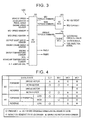
- FIG. 3 is a view of input-output relationships of the vehicle according to the embodiment
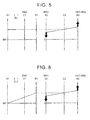
- FIG. 4 is a view showing an operation engagement table of the drive system for the hybrid vehicle according to the embodiment
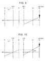
- FIG. 5 is a nomographic chart concerning an HV LOW mode
- FIG. 6 is a nomographic chart concerning an HV HIGH mode
- FIG. 7 is a nomographic chart concerning an MG-stopped first running condition of a single-motor EV mode
- FIG. 1 is a flowchart illustrating operation of the drive system for the hybrid vehicle according to the embodiment of the invention
- FIG. 2 is a skeleton diagram of the vehicle according to the embodiment
- FIG. 3 is a view of input-output relationships of the vehicle according to the embodiment
- FIG. 4 is a view showing an operation engagement table of the drive system for the hybrid vehicle according to the
- FIG. 8 is a nomographic chart concerning a both-drive EV mode
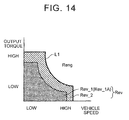
- FIG. 9 is a nomographic chart concerning a second running condition of the single-motor EV mode
- FIG. 10 is a nomographic chart concerning an MG-rotated first running condition of the single-motor EV mode
- FIG. 11 is a view showing a running region in which the vehicle can start by itself
- FIG. 12 is a view showing a running region in which the vehicle cannot start by itself
- FIG. 13 is a time chart concerning control of the embodiment.
- a vehicle 100 is a hybrid vehicle (HV) having an engine 1, a first rotating machine MG1, and a second rotating machine MG2, as power sources.
- the vehicle 100 may be a plug-in hybrid vehicle (PHV) that can be charged with power supplied from an external power supply.
- PSV plug-in hybrid vehicle
- the vehicle 100 includes the engine 1, first planetary gear unit 10, second planetary gear unit 20, first rotating machine MG1, second rotating machine MG2, clutch CL1, brake BK1, HV_ECU 50, MG_ECU 60, and an engine_ECU 70.
- a drive system 1-1 for the hybrid vehicle includes the engine 1, first planetary gear unit 10, second planetary gear unit 20, clutch CL1, and the brake BK1.
- the drive system 1-1 for the hybrid vehicle may further include control units, such as the respective ECUs 50, 60, 70.
- the drive system 1-1 for the hybrid vehicle can be used in an FF (front-engine, front-drive) vehicle, or an RR (rear-engine, rear-drive) vehicle, or the like.
- the drive system 1-1 for the hybrid vehicle is installed on the vehicle 100 such that its axial direction corresponds to the vehicle width direction.
- a speed changing unit is arranged to include the first planetary gear unit 10, clutch CL1, and the brake BK1. Also, a differential unit is arranged to include the second planetary gear unit 20. The clutch CL1 and the brake BK1 are included in a switching device for changing the speed ratio of the first planetary gear unit 10.
- the engine 1 as an engine converts combustion energy of fuel into rotary motion of an output shaft, and delivers the rotary motion.
- the output shaft of the engine 1 is connected to an input shaft 2.
- the input shaft 2 is an input shaft of a power transmission system.
- the power transmission system includes the first rotating machine MG1, second rotating machine MG2, clutch CL1, brake BK1, differential device 30, and so forth.
- the input shaft 2 is disposed coaxially with the output shaft of the engine 1, on an extended line of the output shaft.
- the input shaft 2 is connected to a first carrier 14 of the first planetary gear unit 10.
- the first planetary gear unit 10 of this embodiment is connected to the engine 1, and is installed on the vehicle 100 as a first differential mechanism that transmits rotation of the engine 1.
- the first planetary gear unit 10 is an input-side differential mechanism located closer to the engine 1 than the second planetary gear unit 20.
- the first planetary gear unit 10 is able to change the speed of rotation of the engine 1 and deliver the rotation.
- the first planetary gear unit 10 is of a single pinion type, and has a first sun gear 11, a first pinion gear 12, a first ring gear 13, and the first carrier 14.
- the first pinion gear 12 is disposed between the first sun gear 11 and the first ring gear 13, and engages with the first sun gear 11 and the first ring gear 13, respectively.
- the first pinion gear 12 is rotatably supported by the first carrier 14.
- the first carrier 14 is coupled to the input shaft 2, and rotates as a unit with the input shaft 2. Accordingly, the first pinion gear 12 can rotate (orbit) about the center axis of the input shaft 2, along with the input shaft 2, and can also rotate about the center axis of the first pinion gear 12 (rotate about itself) while being supported by the first carrier 14.
- the clutch CL1 is a clutch device that can couple the first sun gear 11 with the first carrier 14. While the clutch CL1 may be a friction engagement type clutch, for example, it is not limited to this type of clutch, but a clutch device, such as a meshing clutch, may be used as the clutch CL1. For example, the clutch CL1 is hydraulically controlled to be engaged or released. The clutch CL1, when it is in a fully engaged state, couples the first sun gear 11 with the first carrier 14, so that the first sun gear 11 and the first carrier 14 can rotate as a unit. The clutch CL1 in the fully engaged state inhibits differential operation of the first planetary gear unit 10.
- the clutch CL1 when it is in a released state, disconnects the first sun gear 11 and the first carrier 14 from each other, so as to allow the first sun gear 11 and the first carrier 14 to rotate relative to each other.
- the clutch CL1 in the released state allows differential operation of the first planetary gear unit 10.
- the clutch CL1 can be controlled to a half-engaged state.
- the clutch CL1 in the half-engaged state allows differential operation of the first planetary gear unit 10.
- the brake BK1 is a brake device that can inhibit rotation of the first sun gear 11.
- the brake BK1 has an engaging element connected to the first sun gear 11, and an engaging element connected to the vehicle body side, e.g., a case of the power transmission system.
- the brake BK1 may be a friction engagement type clutch device like the clutch CL1, a clutch device, such as a meshing clutch, may be used as the brake BK1.
- the brake BK1 is hydraulically controlled to be engaged or released.
- the brake BK1 when it is in a fully engaged state, can couple the first sun gear 11 with the vehicle body side, so as to inhibit rotation of the first sun gear 11.
- the brake BK1 when it is in a released state, disconnects the first sun gear 11 from the vehicle body side, so as to allow rotation of the first sun gear 11.
- the brake BK1 can be controlled to a half-engaged state.
- the brake BK1 in the half-engaged state allows rotation of the first sun gear 11.
- the second planetary gear unit 20 of this embodiment is installed on the vehicle 100 as a second differential mechanism that connects the first planetary gear unit 10 with drive wheels 32.
- the second planetary gear unit 20 is an output-side differential mechanism located closer to the drive wheels 32 than the first planetary gear unit 10.
- the second planetary gear unit 20 is of a single pinion type, and has a second sun gear 21, a second pinion gear 22, a second ring gear 23, and a second carrier 24.
- the second planetary gear unit 20 is disposed coaxially with the first planetary gear unit 10, and is opposed to the engine 1 with the first planetary gear unit 10 interposed therebetween.
- the second pinion gear 22 is disposed between the second sun gear 21 and the second ring gear 23, and meshes with the second sun gear 21 and the second ring gear 23, respectively.
- the second pinion gear 22 is rotatably supported by the second carrier 24.
- the second carrier 24 is connected to the first ring gear 13, and rotates as a unit with the first ring gear 13.
- the second pinion gear 22 can rotate (orbit) about the center axis of the input shaft 2, along with the second carrier 24, and can also rotate about the center axis of the second pinion gear 22 (rotate about itself) while being supported by the second carrier 24.
- the first ring gear 13 is an output element of the first planetary gear unit 10, and can deliver rotation received by the first planetary gear unit 10 from the engine, to the second carrier 24.
- the second carrier 24 corresponds to a first rotational element connected to the output element of the first planetary gear unit 10.
- a rotary shaft 33 of the first rotating machine MG1 is connected to the second sun gear 21.
- the rotary shaft 33 of the first rotating machine MG1 is disposed coaxially with the input shaft 2, and rotates as a unit with the second sun gear 21.
- the second sun gear 21 corresponds to a second rotational element connected to the first rotating machine MG1.
- a counter drive gear 25 is connected to the second ring gear 23.
- the counter drive gear 25 is an output gear that rotates as a unit with the second ring gear 23.
- the second ring gear 23 corresponds to a third rotational element connected to the second rotating machine MG2 and the drive wheels 32.
- the second ring gear 23 is an output element that can deliver rotation received from the first rotating machine MG1 or the first planetary gear unit 10, to the drive wheels 32.
- the counter drive gear 25 meshes with a counter driven gear 26.
- the counter driven gear 26 is connected to a drive pinion gear 28 via a counter shaft 27.
- the counter driven gear 26 and the drive pinion gear 28 rotate as a unit.
- a reduction gear 35 meshes with the counter driven gear 26.
- the reduction gear 35 is connected to a rotary shaft 34 of the second rotating machine MG2. Namely, rotation of the second rotating machine MG2 is transmitted to the counter driven gear 26 via the reduction gear 35.
- the reduction gear 35 which has a smaller diameter than the counter driven gear 26, reduces the speed of rotation of the second rotating machine MG2, and transmits the rotation to the counter driven gear 26.
- the drive pinion gear 28 meshes with a differential ring gear 29 of the differential device 30.
- the differential device 30 is connected to the drive wheels 32 via right and left drive axles 31.
- the second ring gear 23 is connected to the drive wheels 32, via the counter drive gear 25, counter driven gear 26, drive pinion gear 28, differential device 30, and the drive axles 31.
- the second rotating machine MG2 is connected to a power transmission pathway between the second ring gear 23 and the drive wheels 32, and is able to transmit power to the second ring gear 23 and the drive wheels 32, respectively.
- Each of the first rotating machine MG1 and the second rotating machine MG2 functions as a motor (electric motor) and also function as a generator.
- the first rotating machine MG1 and the second rotating machine MG2 are connected to a battery via inverters.
- the first rotating machine MG1 and the second rotating machine MG2 can convert electric power supplied from the battery into mechanical power, and deliver the mechanical power, and can also convert mechanical power into electric power when driven by power received.
- the electric power generated by the rotating machines MG1, MG2 can be stored in the battery.
- AC synchronous motor-generators may be used, for example.
- the brake BK1, clutch CL1, first planetary gear unit 10, counter drive gear 25, second planetary gear unit 20, and the first rotating machine MG1 are arranged in this order as viewed from one side close to the engine 1, on the same axis as the engine 1.
- the drive system 1-1 of this embodiment is of a plural-axis type in which the input shaft 2 and the rotary shaft 34 of the second rotating machine MG2 are located on different axes.
- the vehicle 100 has the HV_ECU 50, MG_ECU 60, and the engine_ECU 70.
- Each of the ECUs 50, 60, 70 is an electronic control unit having a computer.
- the HV_ECU 50 has a function of performing integrated control on the vehicle 100 as a whole.
- the MG_ECU 60 and the engine_ECU 70 are electrically connected to the HV_ECU 50.
- the MG_ECU 60 can control the first rotating machine MG1 and the second rotating machine MG2. For example, the MG_ECU 60 can adjust a value of current supplied to the first rotating machine MG1, so as to control output torque of the first rotating machine MG1, and can adjust a value of current supplied to the second rotating machine MG2, so as to control output torque of the second rotating machine MG2.
- the engine_ECU 70 can control the engine 1.
- the engine_ ECU 70 can control the opening of an electronic throttle valve of the engine 1, output an ignition signal so as to perform ignition control of the engine 1, and perform fuel injection control, etc. on the engine 1.
- the engine_ECU 70 can control the output torque of the engine 1, through the opening control of the electronic throttle valve, injection control, ignition control, and so forth.
- a vehicle speed sensor To the HV_ECU 50 are connected a vehicle speed sensor, accelerator pedal position sensor, engine speed sensor, MG1 speed sensor, MG2 speed sensor, output shaft speed sensor, engine crank angle sensor, engine water temperature sensor, battery sensor, intake air temperature sensor, ATF temperature sensor, and so forth. From these sensors, the HV_ECU 50 can obtain the vehicle speed, accelerator pedal angle, engine speed, rotational speed of the first rotating machine MG1, rotational speed of the second rotating machine MG2, engine crank angle, engine water temperature, rotational speed of the output shaft of the power transmission system, SOC of the battery, intake air temperature, ATF temperature, and so forth.
- the HV_ECU 50 can calculate required driving force, required power, required torque, etc., which are required to be generated by the vehicle 100, based on the information thus obtained.
- the HV_ECU 50 determines the output torque of the first rotating machine MG1 (which will also be denoted as “MG1 torque"), the output toque of the second rotating machine MG2 (which will also be denoted as “MG2 torque"), and the output torque of the engine 1 (which will also be denoted as "engine torque”), based on the required values thus calculated.
- the HV_ECU 50 outputs a command value of the MG1 torque and a command value of the MG2 torque to the MG_ECU 60. Also, the HV_ECU 50 outputs a command value of the engine torque to the engine ECU 70.
- the HV_ECU 50 controls the clutch CL1 and the brake BK1, respectively, based on a running mode, etc. which will be described later.
- the HV_ECU 50 outputs a command value of a hydraulic pressure (engaging pressure) PbCL1 supplied to the clutch CL1, and a command value of a hydraulic pressure (engaging pressure) PbBK1 supplied to the brake BK1.
- a hydraulic control device that is not illustrated controls the hydraulic pressures supplied to the clutch CL1 and the brake BK1, according to the command values of the respective hydraulic pressures PbCL1, PbBK1 to be supplied.
- the vehicle 100 is able to selectively perform hybrid (HV) running or EV running.
- HV running is a running mode in which the vehicle 100 runs using the engine 1 as a power source.
- the second rotating machine MG2 may be further used as a power source, in addition to the engine 1.
- the EV running is a running mode in which the vehicle 100 runs using at least one of the first rotating machine MG1 and the second rotating machine MG2 as a power source(s). In the EV running, the vehicle 100 is able to run with the engine 1 stopped.
- the drive system 1-1 for the hybrid vehicle according to this embodiment has a single-motor EV mode (single-drive EV mode) in which the vehicle 100 runs using the second rotating machine MG2 as a single power source, and a both-drive EV mode (both-motor EV mode) in which the vehicle 100 runs using the first rotating machine MG1 and the second rotating machine MG2 as power sources.
- FIG. 4 In the engagement table of FIG. 4 , circles in some columns of the clutch CL1 and some columns of the brake BK1 indicate engagement, and blanks indicate release. Also, triangles indicate engagement of one of the clutch CL1 and the brake BK1 and release of the other.
- the second planetary gear unit 20 as the differential unit is basically placed in a differentially operating condition, and the first planetary gear unit 10 as the speed changing unit is switched between LOW and HIGH.
- FIG. 5 is a nomographic chart concerning the HV running mode in the LOW state (which will also be denoted as "HV LOW mode")
- FIG. 6 is a nomographic chart concerning the HV running mode in the HIGH state (which will also be denoted as "HV HIGH mode").
- symbols S1, C1, R1 represent the first sun gear 11, the first carrier 14, and the first ring gear 13, respectively
- symbols S2, C2, R2 represent the second sun gear 21, the second carrier 24, and the second ring gear 23, respectively.
- the HV_ECU 50 engages the clutch CL1, and releases the brake BK1. With the clutch CL1 thus engaged, differential operation of the first planetary gear unit 10 is inhibited, and the rotational elements 11, 13, 14 rotate as a unit. Accordingly, the speed of rotation of the engine 1 is not increased nor reduced, and the rotation of the engine 1 is transmitted at the same speed from the first ring gear 13 to the second carrier 24.
- the HV_ECU 50 releases the clutch CL1, and engages the brake BK1. With the brake BK1 thus engaged, rotation of the first sun gear 11 is inhibited. As a result, the first planetary gear unit 10 is brought into an overdrive (OD) state in which the rotation of the engine 1 received by the first carrier 14 is increased in speed and delivered from the first ring gear 13. Thus, the first planetary gear unit 10 is able to deliver rotation of the engine 1 while increasing the speed of rotation of the engine 1.
- the speed ratio of the first planetary gear unit 10 in the overdrive (OD) state may be set to, for example, 0.7.
- the single-motor EV mode is established by releasing both the clutch CL1 and the brake BK1.
- FIG. 7 is a nomographic chart concerning a MG-stopped first running condition that will be described later, as one of the single-motor EV mode.
- the clutch CL1 and the brake BK1 are released.
- the brake BK1 thus released, the first sun gear 11 is allowed to rotate.
- the clutch CL1 thus released, the first planetary gear unit 10 is able to perform differential operation.
- the HV_ECU 50 causes the second rotating machine MG2 to produce positive torque, via the MG_ECU 60, so as to generate forward driving force in the vehicle 100.
- the second ring gear 23 rotates in the positive direction in accordance with rotation of the drive wheels 32.
- the positive direction mentioned herein is the direction of rotation of the second ring gear 23 when the vehicle 100 runs forward.
- the HV_ECU 50 causes the first rotating machine MG1 to operate as a generator, so as to reduce a drag loss. More specifically, the HV_ECU 50 applies slight torque to the first rotating machine MG1 so that the first rotating machine MG1 generates electric power while the rotational speed of the first rotating machine MG1 is substantially equal to 0. Thus, the vehicle is able to run without rotating the first rotating machine MG1. In this manner, the drag loss of the first rotating machine MG1 can be reduced.
- running the vehicle without rotating the first rotating machine MG1 may include running the vehicle while varying the MG1 speed within a given range according to the accuracy of rotational speed control of the first rotating machine MG1.
- running the vehicle without rotating the first rotating machine MG1 includes running the vehicle 100 in a condition where the MG1 speed varies within the range of +50rpm to -50rpm.
- the MG1 speed may not be applied.
- the MG1 speed may also be made equal to 0 (or within a given range) by locking the d-axis of the first rotating machine MG1.
- the first ring gear 13 is forced to rotate in the positive direction along with the second carrier 24. Since the first planetary gear unit 10 is in a neutral state where the clutch CL1 and the brake BK1 are released, the engine 1 is not forced to rotate, and rotation of the first carrier 14 is stopped. Accordingly, a large amount of regenerative energy can be taken.
- the first sun gear 11 rotates idle in the negative direction.
- the neutral state of the first planetary gear unit 10 is a state in which power is not transmitted between the first ring gear 13 and the first carrier 14, namely, a state in which the engine 1 and the second planetary gear unit 20 are disconnected from each other, and power transmission therebetween is cut off. If at least one of the clutch CL1 and the brake BK1 is engaged, the first planetary gear unit 10 is placed in a connecting state for connecting the engine 1 with the second planetary gear unit 20.
- engine brake may be used at the same time.
- the clutch CL1 or the brake BK1 By engaging the clutch CL1 or the brake BK1, it is possible to connect the engine 1 with the drive wheels 32, and apply engine brake to the drive wheels 32. If the clutch CL1 or brake BK1 is engaged in the single-motor EV mode, as indicated by the triangles in FIG. 4 , the engine 1 is forced to rotate, and the engine speed is raised by the first rotating machine MG1 so that the vehicle is brought into an engine brake condition.
- the HV_ECU 50 engages the clutch CL1 and the brake BK1.
- the clutch CL1 is engaged, so that differential operation of the first planetary gear unit 10 is inhibited, and the brake BK1 is engaged, so that rotation of the first sun gear 11 is inhibited. Accordingly, rotation of all rotational elements of the first planetary gear unit 10 is stopped. Since rotation of the first ring gear 13 as the output element is inhibited, the second carrier 24 connected to the first ring gear 13 is locked, i.e., its rotational speed becomes equal to 0.
- the HV_ECU 50 causes the first rotating machine MG1 and the second rotating machine MG2 to produce torque for driving the vehicle.
- the first rotating machine MG1 produces negative torque and rotates in the negative direction when the vehicle runs forward, so that positive torque can be delivered from the second ring gear 23.
- the first rotating machine MG1 produces positive torque and rotates in the positive direction, so that negative torque can be delivered from the second ring gear 23.
- the switching device consisting of the clutch CL1 and the brake BK1 switches the first planetary gear unit 10 between a condition where differential operation of the first planetary gear unit 10 is inhibited, and a condition where differential operation of the first planetary gear unit 10 is allowed, so as to change the speed ratio of the first planetary gear unit 10.
- the drive system 1-1 for the hybrid vehicle can be switched between the HV HIGH mode and the HV LOW mode, by the speed changing unit including the first planetary gear unit 10, clutch CL1 and the brake BK1, so as to improve the transmission efficiency of the vehicle 100.
- the second planetary gear unit 20 as the differential unit is connected in series with the downstream side of the speed changing unit. Since the first planetary gear unit 10 is operable in the overdrive state, the first rotating machine MG1 need not provide significantly increased torque.
- the HV_ECU 50 selects EV running, in a low-load motor running region in which the vehicle speed is low and the required driving force is small. In the motor running region, the single-motor EV mode is selected at a low load, and the both-drive EV mode is selected at a high load. A region in which the vehicle speed and the load are higher than those of the motor running region is an engine running region.
- the HV_ECU 50 selects the HV LOW mode in a low- and middle-vehicle-speed, high-load region of the engine running region, and selects the HV HIGH mode in a high-vehicle-sped, low-load region. By placing the speed changing unit in the overdrive state when the vehicle speed is high and the load is low, the fuel economy can be improved.
- the speed of rotation of the engine 1 is changed through switching between the HV HIGH mode and the HV LOW mode, and the resulting rotation is delivered, so that two mechanical points are provided, and the fuel efficiency can be improved.
- the mechanical point is a highly efficient operating point at which the entire power received by the planetary gear units 10, 20 is mechanically transmitted to the counter drive gear 25 without passing through any electric path.
- the first planetary gear unit 10 can increase the speed of rotation of the engine 1, and deliver the rotation from the first ring gear 13. Accordingly, in addition to a mechanical point provided in the case where the first planetary gear unit 10 is not provided and the engine 1 is directly connected to the second carrier 24, the drive system 1-1 for the hybrid vehicle has another mechanical point on the high gear side. Namely, the drive system 1-1 for the hybrid vehicle has two mechanical points on the high gear side. Thus, the drive system 1-1 for the hybrid vehicle can realize a hybrid system with which the fuel economy can be improved through improvement of the transmission efficiency during high-speed running.
- the drive system 1-1 for the hybrid vehicle can inhibit rotation of the output element of the first planetary gear unit 10 and the input element of the second planetary gear unit 20, by engaging the clutch CL1 and the brake BK1 of the speed changing unit, so as to enable the vehicle to run in the both-drive EV mode. Therefore, there is no need to separately provide a clutch, or the like, for establishing the both-drive EV mode, and the arrangement of the system is simplified.
- the speed reduction ratio of the second rotating machine MG2 can be set to a large value. Also, a compact arrangement can be achieved by the FF or RR layout.
- the first rotating machine MG1 When the vehicle runs backward while the engine is running, the first rotating machine MG1 operates as a generator to generate electric power, and the second rotating machine MG2 operating as a motor rotates in the negative direction to produce negative torque, so as to run the vehicle backward.
- the second rotating machine MG2 When the battery is in a sufficiently charged state, the second rotating machine MG2 may rotate alone in the reverse direction in the single-drive EV mode, to effect motor running. It is also possible to run the vehicle backward in the both-drive EV mode by fixing the second carrier 24.
- the HV_ECU 50 can perform coordinated speed-change control for changing the speed ratios of the first planetary gear unit 10 and the second planetary gear unit 20 at the same time.
- the HV_ECU 50 increases the speed ratio of one of the first planetary gear unit 10 and the second planetary gear unit 20, and reduces the speed ratio of the other.
- the HV_ECU 50 Upon switching from the HV HIGH mode to the HV LOW mode, the HV_ECU 50 changes the speed ratio of the second planetary gear unit 20 to the higher gear side in synchronization with switching of the modes. This makes it possible to curb or reduce discontinuous change of the speed ratio in the whole system of the vehicle 100 from the engine 1 to the drive wheels 32, and reduce the degree of change of the speed ratio. By curbing change of the speed ratio in the system from the engine 1 to the drive wheels 32, it is possible to reduce the amount of adjustment of the engine speed caused by change of the speed ratio, or make the adjustment of the engine speed unnecessary.
- the HV_ECU 50 changes the speed ratios of the first planetary gear unit 10 and the second planetary gear unit 20 in coordination with each other, so as to continuously change the speed ratio of the vehicle 100 as a whole to the lower gear side.
- the HV_ECU 50 Upon switching from the HV LOW mode to the HV HIGH mode, on the other hand, the HV_ECU 50 changes the speed ratio of the second planetary gear unit 20 to the lower gear side in synchronization with switching of the modes. This makes it possible to curb or reduce discontinuous change of the speed ratio in the vehicle 100 as a whole, and reduce the degree of change of the speed ratio. For example, the HV_ECU 50 changes the speed ratios of the first planetary gear unit 10 and the second planetary gear unit 20 in coordination with each other, so as to continuously change the speed ratio of the vehicle 100 as a whole to the higher gear side.
- the speed ratio of the second planetary gear unit 20 is adjusted by controlling the rotational speed of the first rotating machine MG1, for example.
- the HV_ECU 50 controls the first rotating machine MG1 so as to steplessly change the speed ratio between the input shaft 2 and the counter drive gear 25.
- the whole system including the planetary gear units 10, 20, first rotating machine MG1, clutch CL1 and the brake BK1, namely, a speed changing system including the differential unit and the speed changing unit operates as an electric continuously variable transmission. Since the speed ratio of the speed changing system including the differential unit and the speed changing unit is variable in a wide range, the speed ratio from the differential unit to the drive wheels 32 can be set to a relatively large value. Also, power circulation during high-speed running in the HV running mode is reduced.
- the engine 1 can start by itself, and the engine 1 can also start the engine 1 using MG1 torque.
- the engine 1 can start by increasing its rotational speed without depending on torque from the outside, in other words, can start by itself in a condition where it is disconnected from the first rotating machine MG1, second rotating machine MG2, drive wheels 32, and so forth.
- the engine 1 of this embodiment is a direct-injection-type engine in which fuel is directly injected into cylinders.
- the engine 1 can start rotating with combustion energy of fuel generated in the cylinders, from a condition where its rotation is stopped, and complete starting after increasing the rotational speed.
- the engaging device in question When the engine speed increases, and the differential rotational speed of the clutch CL1 or brake BK1 becomes close to 0, the engaging device in question is engaged, so that the vehicle shifts to the HV running mode. For example, if the differential rotational speed of the clutch CL1 becomes close to 0, the clutch CL1 is engaged, so that the vehicle shifts to the HV LOW mode.
- the vehicle 100 can start the engine 1 (which will be called “assisted starting”), by cranking the engine through motoring for increasing the engine speed with MG1 torque.
- assisted starting the engine 1 that is stopped starts being rotated by use of the MG1 torque, and the engine speed is increased so that the engine is started.
- the engine 1 when the engine 1 is started from the single-motor EV mode, it is desirable to reduce a lag in starting of the engine 1, and furthermore, it is preferable to achieve both reduction of electric power consumption (suppression of efficiency reduction), and reduction of the lag in starting of the engine 1.
- the vehicle 100 according to this embodiment is installed with the engine 1 that can start by itself, and can shift to HV running by quickly starting the engine with a reduced starting lag under conditions where the engine 1 can start by itself.
- the engine 1 cannot start by itself in some cases.
- the engine 1 cannot start by itself in the case where the temperature of the engine 1 is low, and the case where the stop positions of the pistons are not within a range in which the engine 1 can start by itself.
- the engine_ECU 70 determines whether the engine 1 can start by itself, and outputs a signal indicative of whether the engine can or cannot start by itself, to the HV_ECU 50.
- the engine 1 needs to be started using the MG1 torque.
- a time lag in starting may be large, as will be described below.
- the vehicle runs with the clutch CL1 and the brake BK1 released, so that a drag loss of the first rotating machine MG1 can be reduced. Since the first rotating machine MG1 is stopped due to cogging torque, or the like, electric current for counterbalancing back electromotive force need not flow from the battery, and the electric power consumption is reduced. Generally, when torque is transmitted to the first rotating machine MG1, and the MG1 speed deviates from 0 rpm, an electric loss due to current (field-weakening current) that counterbalances back electromotive force, or a mechanical loss of a bearing appears.
- the engine 1 is started by executing the steps of (1) making the rotational speed of the second carrier 24 equal to 0 through rotational speed control of the first rotating machine MG1, (2) engaging the clutch CL1 or the brake BK1, and (3) increasing the engine speed with the MG1 torque, for example. Accordingly, in the assisted starting, a larger amount of time is required for starting of the engine 1, as compared with the case of self-starting. The driver feels this delay as an engine starting lag.
- the drive system 1-1 for the hybrid vehicle has a first running condition and a second running condition in the single-motor EV mode, and can selectively establish the first running condition or the second running condition.
- the first running condition is a running condition in which the vehicle runs using the second rotating machine MG2 as a power source and differentially operating the first planetary gear unit 10 as the speed changing unit. In the first running condition, differential operation of the first planetary gear unit 10 is allowed, and the vehicle is able to run without rotating the first rotating machine MG1 as shown in FIG. 7 , for example.
- the vehicle runs using the second rotating machine MG2 as a power source, without differentially operating the first planetary gear unit 10.
- the rotational speeds of the three rotational elements of the first planetary gear unit 10 are made equal.
- the drive system 1-1 for the hybrid vehicle establishes the second running condition, by stopping rotation of the second carrier 24 and the first ring gear 13, through rotational speed control of the first rotating machine MG1, and engaging the clutch CL1 or the brake BK1.
- the clutch CL1 or the brake BK1 is engaged, so that the vehicle can run without differentially operating the first planetary gear unit 10.
- the rotational speeds of the first sun gear 11 and the first ring gear 13 are equal to the rotational speed of the engine 1, namely, equal to 0.
- the engine 1 can be started through cranking, with torque immediately transmitted from the first rotating machine MG1 to the engine 1. Accordingly, a lag in assisted starting can be reduced, and the response of engine starting can be improved.
- the first running condition is further divided into an MG-stopped first running condition and an MG-rotated first running condition.
- the MG-stopped first running condition is a running condition in which the vehicle runs while differentially operating the first planetary gear unit 10, without rotating the first rotating machine MG1, as shown in FIG. 7 .
- the MG-rotated first running condition is a running condition in which the vehicle runs while differentially operating the first rotating machine MG1, and rotating the first rotating machine MG1, as shown in FIG. 10 .
- the rotational speed (absolute value) of the second carrier 24 in the MG-rotated first running condition is smaller than the rotational speed (absolute value) of the second carrier 24 in the MG-stopped first running condition.
- it is desirable that the MG1 rotational speed indicates negative rotation.
- the lag in assisted starting can be reduced, to be smaller than that in the MG-stopped first running condition.
- the required amount of change (see ⁇ N2 of FIG. 10 ) in the rotational speed of the second carrier 24 when the assisted starting is initiated from the MG-rotated first running condition is smaller than the required amount of change (see ⁇ N1 of FIG. 7 ) in the rotational speed of the second carrier 24 when the assisted starting is initiated from the MG-stopped first running condition. Accordingly, when the assisted starting is effected from the MG-rotated first running condition, the engine starting can be completed in a shorter time than that in the case where the assisted starting is effected from the MG-stopped first running condition.
- running regions in the case where the engine 1 can start by itself are specified, as shown in FIG. 11 .
- running regions in the case where the engine 1 cannot start by itself are specified, as shown in FIG. 12 .
- the horizontal axis indicates the vehicle speed
- the vertical axis indicates output torque. The output torque is required torque or target torque based on the accelerator pedal angle, running conditions, running environment, etc.
- the running region is divided into an engine running region Reng in which the vehicle runs in the HV running mode, and an EV running region Rev in which the vehicle runs in the EV running mode.
- the engine running region Revn and the EV running region Rev are separated by a boundary line L1.
- the EV running region Rev is a region closer to the origin than the boundary line L1
- the engine running region Reng is a region on the opposite side of the boundary line L1 remote from the origin. Namely, the EV running mode is selected when the vehicle speed and the output torque are relatively low, and the HV running mode is selected when the vehicle speed and the output torque are relatively high.
- the entire area of the EV running region Rev is a first EV running region Rev_1 in which the vehicle runs in the first running condition.
- the entire area of the first EV running region Rev_1 is an MG-stopped running region Rev_1A in which the vehicle runs in the MG-stopped first running condition.
- the running region is divided into an engine running region Reng in which the vehicle runs in the HV running mode, a first EV running region Rev_1 in which the vehicle runs in the first running condition of the EV running mode, and a second EV running region Rev_2 in which the vehicle runs in the second running condition of the EV running mode.
- the first EV running region Rev_1 is further divided into an MG-stopped running region Rev_1A and an MG-rotated running region Rev_1B.
- the MG-stopped running region Rev_1A is a running region in which the vehicle runs in the MG-stopped first running condition.
- the MG-rotated running region Rev_1B is a running region in which the vehicle runs in the MG-rotated first running condition.
- the engine running region Reng and the second EV running region Rev_2 are separated by a boundary line L1.
- the second EV running region Rev_2 and the MG-rotated running region Rev_1B are separated by a boundary line L2.
- the MG-rotated running region Rev_1B and the MG-stopped running region Rev_1A are separated by a boundary line L3.
- the MG-stopped running region Rev_1A, MG-rotated running region Rev_1B, second EV running region Rev_2, and the engine running region Reng are provided in the order of description, from the origin toward a high-vehicle-speed, high-output-torque region.
- the electric power economy is prioritized when the vehicle runs in urban areas, etc.
- the electric power economy is often prioritized over reduction of the lag in engine starting.
- the frequency of running at a low load is high.
- the first running condition that is superior in terms of electric power economy is more likely to selected in a low-load region, than the second running region.
- the MG-stopped first running condition is selected. In this case, the vehicle runs without rotating the first rotating machine MG1, so that the highest priority can be given to improvement of the electric power economy and suppression of reduction of the efficiency. If the vehicle speed and the output torque are higher than those of the MG-stopped running region Rev_1A, the MG-rotated first running condition is selected. In this case, it is possible to reduce an engine starting lag in assisted starting, while making an attempt to improve the electric power economy and suppress reduction of the efficiency. If the vehicle speed and the output torque are higher than those of the MG-rotated running region Rev_1B, the second running condition is selected. In this case, it is possible to further prioritize reduction of the engine starting lag in assisted starting, as compared with the MG-rotated first running condition.
- the region in which the vehicle runs in the second running condition is enlarged to be larger than that in the case where the engine 1 can start by itself.
- the lag or delay in starting of the engine 1 is reduced.
- the second EV running region Rev_2 is not provided.
- the second EV running region Rev_2 is provided, as shown in FIG. 12 , and the second EV running region Rev_2 is larger than that in the case where the engine 1 can start by itself.
- the second EV running region Rev_2 is reduced as compared with the case where the engine 1 cannot start by itself, and the reduction includes making the area of the second EV running region Rev_2 equal to 0, or not providing the second EV running region Rev_2.
- the second EV running region Rev_2 thus made larger when the engine 1 cannot start by itself, the starting lag when the engine 1 is started is reduced.
- a control flow shown in FIG. 1 is repeatedly executed at given intervals during EV running, for example.
- the control flow shown in FIG. 1 may be executed when the vehicle runs in the single-motor EV running mode.
- (a) indicates a self-startability flag
- (b) indicates engine speed
- (c) indicates MG1 torque
- (d) indicates MG1 speed
- (e) indicates MG2 torque
- (f) indicates MG2 speed
- (g) indicates hydraulic pressure supplied to the clutch CL1
- (h) indicates accelerator pedal angle
- (i) indicates vehicle speed.
- step S10 the HV_ECU 50 determines whether independent ignition starting is possible.
- the HV_ECU 50 makes the determination of step S10, based on the self-startability flag received from the engine_ECU 70.
- the self-startability flag is set to ON when the engine 1 can start by itself, and is set to OFF when the engine 1 cannot start by itself.
- the self-startability flag is ON, the HV_ECU 50 determines that the independent ignition starting is possible. If it is determined, as a result of determination in step S10, that the independent ignition starting is possible (step S10 - Y), the control proceeds to step S60. If not (step S10 - N), the control proceeds to step S20.
- step S10 determines whether independent ignition starting is possible.
- the self-startability flag switches from ON to OFF, and the engine changes from a condition where it is determined that independent ignition starting is possible, to a condition where it is determined that independent ignition starting is impossible.
- the engine 1 can start by itself, and therefore, the vehicle runs in the MG1-stopped first running condition.
- step S20 the HV_ECU 50 determines whether the vehicle is running in the first EV running region Rev_1 or the second EV running region Rev_2. Referring to the map of running regions shown in FIG. 12 , for example, the HV_ECU 50 determines which running region of the first EV running region Rev_1 and the second EV running region Rev_2 in which the operating point determined from the current vehicle speed and output torque lies. After execution of step S20, the control proceeds to step S30.
- step S30 the HV_ECU 50 determines whether the current operating point lies in the first EV running region Rev_1. If it is determined, as a result of the determination, that the current operating point lies in the first EV running region Rev_1 (step S30 - Y), the control proceeds to step S50. If not (step S30 - N), the control proceeds to step S40.
- step S40 the HV_ECU 50 executes running in the second EV running region Rev_2, namely, running in the second running condition.
- the HV_ECU 50 outputs the rotational speed at which rotation of the second carrier 24 can be stopped, to the MG_ECU 60, as a command value of the MG1 speed.
- this control flow ends.
- the second running condition is selected at time t1. As a result, over a period from time t1 to time t2, the MG1 torque is a negative torque, the MG1 speed indicates negative rotation, and the rotational speed increases.
- the MG1 torque is delivered to the second ring gear 23, due to drag torque or inertia torque of the shaft of the second carrier 24 and the first planetary gear unit 10.
- the MG2 torque is reduced so as to counterbalance the output torque, so that shock caused by torque variation is suppressed.
- rotation of the second carrier 24 and the first ring gear 13 is stopped, and the clutch CL1 is engaged to place the first planetary gear unit 10 in a non-differential operating state, so that the shift to the second running condition is completed.
- the brake BK1 may be engaged, in place of the clutch CL1, so as to place the first planetary gear unit 10 in the non-differential operating state.
- step S50 the HV_ECU 50 determines whether the vehicle is running in the MG-stopped running region Rev_1A or the MG-rotated running region Rev_1B. Referring to the map of FIG. 12 , the HV_ECU 50 determines which of the MG-stopped running region Rev_1A and the MG-rotated running region Rev_1B in which the current operating point lies. If the current operating point lies in the MG-stopped running region Rev_1A, the HV_ECU 50 sends a command to the MG_ECU 60 so as to stop the first rotating machine MG1.
- the HV_ECU 50 calculates a target value of the MG1 speed, and outputs the calculated target value to the MG_ECU 60 as a command value of the MG1 speed.
- the command value is at least higher than the rotational speed in the MG-stopped first running condition, and is calculated by a predetermined method.
- the command value of the MG1 speed in the MG-rotated first running condition may be a constant value, or may vary according to the vehicle speed, etc.
- step S60 the HV_ECU 50 determines whether the vehicle is running in the first EV running region Rev_1. Since the engine 1 can start by itself, the HV_ECU 50 makes a determination on running regions, by referring to the map shown in FIG. 11 . In the map shown in FIG. 11 , the entire area of the EV running region Rev is the first EV running region Rev_1, and is also the MG-stopped running region Rev_1A. The HV_ECU 50 sends a command to the MG_ECU 60 so as to stop the first rotating machine MG1. After execution of step S60, this control flow ends.
- the drive system 1-1 for the hybrid vehicle enlarges the region in which the vehicle runs in the second running condition, so that the region becomes larger than that in the case where the engine 1 can start by itself.
- reduction of the efficiency of the vehicle 100 can be suppressed, and the delay in engine starting can also be reduced.
- the region in which the vehicle runs in the first running condition has the MG-rotated running region Rev_1B in which the vehicle runs while rotating the first rotating machine MG1, and the MG-stopped running region Rev_1A in which the vehicle runs without rotating the first rotating machine MG1.
- the running condition in which suppression of reduction in the efficiency of the vehicle 100 is relatively prioritized, and the running condition in which reduction of the delay in engine starting is relatively prioritized can be selectively established.
- the second EV running region Rev_2 is not provided in the case where the engine 1 can start by itself in this embodiment, the second EV running region Rev_2 may be provided in the case where the engine 1 can start by itself. However, the second EV running region Rev_2 in the case where the engine 1 can start by itself is made smaller than the second EV running region in the case where the engine 1 cannot start by itself.
- the first EV running region Rev_1 and the engine running region Reng are provided adjacent to each other. Instead, the region in which the vehicle runs in the both-drive EV mode may be provided between the first EV running region Rev_1 and the engine running region Reng. Also, in the case where the engine 1 cannot start by itself (see FIG. 12 ), the second EV running region Rev_2 and the engine running region Reng are provided adjacent to each other. Instead, the region in which the vehicle runs in the both-drive EV mode may be provided between the second EV running region Rev_2 and the engine running region Reng.
- self-starting of the engine 1 means that the engine 1 autonomously start without receiving assist torque from the outside until engine starting is completed.
- the increase of the engine speed may be assisted by MG1 torque after engagement of the clutch CL1 or the brake BK1. That is, self-starting may include the case where the increase of the engine speed is assisted by the MG1 torque while the engine speed is being increased, so that engine starting is completed.
- a starting method in which the engine 1 at least starts increasing the engine speed autonomously and reaches completion of engine starting may be called self-starting.
- the engine_ECU 70 may determine that the engine 1 cannot start by itself, under a situation where the engine 1 can start by itself, but starting shock is large.
- the engine 1 may include a starter.
- self-starting of the engine 1 includes starting by means of the starter.
- the starter fails, the engine_ECU 70 determines that the engine 1 cannot start by itself.
- FIG. 14 is a view showing running regions according to a first modified example of the embodiment.
- the entire area of the first EV running region Rev_1 is set as the MG-stopped running region Rev_1A.
- the entire area of the first EV running region Rev_1 may be set as the MG-rotated running region Rev_1B.
- the entire area of the first EV running region Rev_1 may be set as the MG-stopped running region Rev_1A as shown in FIG. 14 , when a driver's intention to accelerate the vehicle is small, and the entire area of the first EV running region Rev_1 may be set as the MG-rotated running region Rev_1B when the driver's intention to accelerate the vehicle is large.
- the magnitude of the driver's intention to accelerate the vehicle can be detected or estimated based on, for example, the selected mode, acceleration applied to the vehicle, the rate of change of the accelerator pedal angle, shifting operation, and so forth.
- a vehicle that can be selectively placed in a power mode, a normal mode, or an economy mode, through a pushing operation on a switch, or the like
- the power mode when the power mode is selected, it is determined that the intention to accelerate the vehicle is larger than that in the case where the normal mode or the economy mode is selected.
- the driver has a large intention to accelerate the vehicle when he/she performs a driving operation so that the acceleration/deceleration G of the vehicle 100 or the lateral G caused by turning becomes large.
- the rate of increase of the accelerator pedal angle is large, it can be determined that the intention to accelerate the vehicle is larger than that in the case where the rate of increase of the accelerator pedal angle is small.
- the shifting operation to shift the transmission to a lower-speed gear position can be determined as indicating an increase of the intention to accelerate the vehicle.
- the electric power economy is prioritized, and the entire area of the first EV running region Rev_1 is set as the MG-stopped running region Rev_1A.
- the remaining amount of charge of the battery is large, reduction of the engine starting lag is prioritized, and the entire area of the first EV running region Rev_1 is set as the MG-rotated running region Rev_1B.
- the region in which the vehicle runs in the second running condition may be variable.
- the size of the second EV running region Rev_2 may be changed according to the magnitude of the driver's intention to accelerate the vehicle.
- the second EV running region Rev_2 is larger than that in the case where the driver's intention to accelerate the vehicle is small.
- the second EV running region Rev_2 may be enlarged by enlarging the second EV running region Rev_2 toward the low-vehicle-speed side or low-output-torque side.
- the second EV running region Rev_2 in the case where the remaining amount of charge of the battery is large may be made larger than the second EV running region Rev_2 in the case where the remaining amount of charge of the battery is small.
- the MG-rotated running region Rev_1B may be variable.
- the size of the MG-rotated running region Rev_1B may be changed according to the magnitude of the driver's intention to accelerate the vehicle.
- the MG-rotated running region Rev_1B in the case where the intention to accelerate the vehicle is large is larger than the MG-rotated running region Rev_1B in the case where the intention to accelerate the vehicle is small.
- the MG-rotated running region Rev_1B may be enlarged by enlarging the MG-rotated running region Rev_1B toward the low-vehicle-speed side or low-output-torque side.
- the MG-rotated running region Rev_1B in the case where the remaining amount of charge of the battery is large may be made larger than the MG-rotated running region Rev_1B in the case where the remaining amount of charge of the battery is small.
- the rotational speed of the second carrier 24 and the first ring gear 13 may be variable.
- the rotational speed of the second carrier 24 is smaller in a region close to the second EV running region Rev_2, than that in a region remote from the second EV running region Rev_2.
- the rotational speed of the second carrier 24 may be reduced as the operating point moves from the MG-stopped running region Rev_1 side to the second EV running region Rev_2 side.
- the power transmission system consisting of the engine, speed changing unit, and the differential unit comprised of three shafts, wherein the output shaft of the engine is coupled to the input shaft of the speed changing unit, the output shaft of the speed changing unit is coupled to a first shaft of the differential unit, the first rotating machine is coupled to a second shaft of the differential unit, and the second rotating machine is coupled to a third shaft, and wherein first rotating machine running in which the speed changing unit performs differential operation and second rotating machine running in which the speed changing unit does not perform differential operation are possible, the engine starts by itself or starts with an aid of the first rotating machine, and a region of the second rotating machine running is larger in the case where the engine cannot start by itself, than that in the case where the engine can start by itself.”
Landscapes
- Engineering & Computer Science (AREA)
- Mechanical Engineering (AREA)
- Chemical & Material Sciences (AREA)
- Combustion & Propulsion (AREA)
- Transportation (AREA)
- General Engineering & Computer Science (AREA)
- Automation & Control Theory (AREA)
- Hybrid Electric Vehicles (AREA)
- Electric Propulsion And Braking For Vehicles (AREA)
Abstract
Description
- This invention relates to a drive system for a hybrid vehicle.
- Conventionally, there are hybrid vehicles. For example,
Patent Document 1 discloses a technology of a drive system of a hybrid vehicle including a speed changing mechanism that changes the speed of rotation of an internal combustion engine and transmits the rotation to a power distribution mechanism, a first transmission shaft that transmits power from the internal combustion engine to the speed changing mechanism, and a second transmission shaft that transmits power delivered from the speed changing mechanism to the power distribution mechanism. In the drive system of the hybrid vehicle ofPatent Document 1, the speed changing mechanism has a differential mechanism in which two sets of planetary gear units are combined, a first brake B1 that can stop rotation of a ring gear R1 of the differential mechanism, a second brake B2 that can stop rotation of a ring gear R2, and a clutch C that permits or inhibits power transmission from the first transmission shaft to the ring gear R1. - Patent Document 1: Japanese Patent Application Publication No.
2009-190694 - In a hybrid vehicle having an engine that can start by itself, it is desirable that a delay in starting of the engine can be reduced. For example, in a hybrid vehicle having a clutch that can disconnect the engine from the rest of the vehicle, it is preferable that a delay in starting of the engine can be reduced even in a situation where the engine cannot start by itself.
- An object of the invention is to provide a drive system for a hybrid vehicle in which a delay in starting of an engine can be reduced.
- A drive system for a hybrid vehicle of the invention is characterized by including an engine, a first differential mechanism that is connected to the engine, and transmits rotation of the engine, a second differential mechanism that connects the first differential mechanism with drive wheels, a switching device that changes a speed ratio of the first differential mechanism, a first running condition, and a second running condition. The drive system is characterized in that the second differential mechanism has a first rotational element connected to an output element of the first differential mechanism, a second rotational element connected to a first rotating machine, and a third rotational element connected to a second rotating machine and the drive wheels, the first running condition is a running condition in which the vehicle runs using the second rotating machine as a power source, while differentially operating the first differential mechanism, the second running condition is a running condition in which the vehicle runs using the second rotating machine as a power source, without differentially operating the first differential mechanism, and a region in which the vehicle runs in the second running condition in the case where the engine cannot start by itself is larger than that in the case where the engine can start by itself.
- In the drive system for the hybrid vehicle as described above, it is preferable that the region in which the vehicle runs in the second running condition is a higher-load-side region than a region in which the vehicle runs in the first running condition.
- In the drive system for the hybrid vehicle as described above, it is preferable that, when the engine cannot start by itself, a region in which the vehicle runs in the first running condition has a region in which the vehicle runs while rotating the first rotating machine, and a region in which the vehicle runs without rotating the first rotating machine.
- In the drive system for the hybrid vehicle as described above, it is preferable that the region in which the vehicle runs in the second running condition in the case where a driver's intention to accelerate the vehicle is large is larger than that in the case where the driver's intention to accelerate the vehicle is small.
- In the drive system for the hybrid vehicle as described above, it is preferable that the region in which the vehicle runs while rotating the first rotating machine is larger in the case where the driver's intention to accelerate the vehicle is large than that in the case where the driver's intention to accelerate the vehicle is small.
- In the drive system for the hybrid vehicle as described above, it is preferable that the region in which the vehicle runs while rotating the first rotating machine is provided between the region in which the vehicle runs without rotating the first rotating machine, and the region in which the vehicle runs in the second running condition, and in the region in which the vehicle runs while rotating the first rotating machine, a rotational speed of the first rotational element is smaller in a region close to the region in which the vehicle runs in the second running condition, than that in a region remote from the region in which the vehicle runs in the second running condition.
- The drive system for the hybrid vehicle according to the invention includes the first running condition in which the vehicle runs using the second rotating machine as the power source and differentially operating the first differential mechanism, and the second running condition in which the vehicle runs using the second rotating machine as the power source, without differentially operating the first differential mechanism. In the case where the engine cannot start by itself, the region in which the vehicle runs in the second running condition is larger than that in the case where the engine can start by itself. The drive system for the hybrid vehicle according to the invention yields an effect of reducing a delay in starting of the engine.
-
- [
FIG. 1] FIG. 1 is a flowchart illustrating operation of a drive system for a hybrid vehicle according to one embodiment. - [
FIG. 2] FIG. 2 is a skeleton diagram of a vehicle according to the embodiment. - [
FIG. 3] FIG. 3 is a view of input-output relationships of the vehicle according to the embodiment. - [
FIG. 4] FIG. 4 is a view showing an operation engagement table of the drive system for the hybrid vehicle according to the embodiment. - [
FIG. 5] FIG. 5 is a nomographic chart concerning an HV LOW mode. - [
FIG. 6] FIG. 6 is a nomographic chart concerning an HV HIGH mode. - [
FIG. 7] FIG. 7 is a nomographic chart concerning an MG-stopped first running condition of a single-motor EV mode. - [
FIG. 8] FIG. 8 is a nomographic chart concerning a both-drive EV mode. - [
FIG. 9] FIG. 9 is a nomographic chart concerning a second running condition of the single-motor EV mode. - [
FIG. 10] FIG. 10 is a nomographic chart concerning an MG-rotated first running condition of the single-motor EV mode. - [
FIG. 11] FIG. 11 is a view showing a running region in which an engine can start by itself. - [
FIG. 12] FIG. 12 is a view showing a running region in which the engine cannot start by itself. - [
FIG. 13] FIG. 13 is a time chart concerning control of the embodiment. - [
FIG. 14] FIG. 14 is a view showing running regions according to a first modified example of the embodiment. - In the following, a drive system for a hybrid vehicle according to one embodiment of the invention will be described in detail with reference to the drawings. It is to be understood that this invention should not be limited to this embodiment. Also, constituent elements in the following embodiment include those that can be easily conceived by a person skilled in the art, or those that are substantially the same elements.
- Referring to
FIG. 1 through FIG. 14 , the embodiment will be described. This embodiment relates to a drive system for a hybrid vehicle.FIG. 1 is a flowchart illustrating operation of the drive system for the hybrid vehicle according to the embodiment of the invention,FIG. 2 is a skeleton diagram of the vehicle according to the embodiment,FIG. 3 is a view of input-output relationships of the vehicle according to the embodiment,FIG. 4 is a view showing an operation engagement table of the drive system for the hybrid vehicle according to the embodiment,FIG. 5 is a nomographic chart concerning an HV LOW mode,FIG. 6 is a nomographic chart concerning an HV HIGH mode,FIG. 7 is a nomographic chart concerning an MG-stopped first running condition of a single-motor EV mode,FIG. 8 is a nomographic chart concerning a both-drive EV mode,FIG. 9 is a nomographic chart concerning a second running condition of the single-motor EV mode,FIG. 10 is a nomographic chart concerning an MG-rotated first running condition of the single-motor EV mode,FIG. 11 is a view showing a running region in which the vehicle can start by itself,FIG. 12 is a view showing a running region in which the vehicle cannot start by itself, andFIG. 13 is a time chart concerning control of the embodiment. - As shown in
FIG. 2 , avehicle 100 according to this embodiment is a hybrid vehicle (HV) having anengine 1, a first rotating machine MG1, and a second rotating machine MG2, as power sources. Thevehicle 100 may be a plug-in hybrid vehicle (PHV) that can be charged with power supplied from an external power supply. As shown inFIG. 2 andFIG. 3 , thevehicle 100 includes theengine 1, firstplanetary gear unit 10, secondplanetary gear unit 20, first rotating machine MG1, second rotating machine MG2, clutch CL1, brake BK1, HV_ECU 50, MG_ECU 60, and anengine_ECU 70. - A drive system 1-1 for the hybrid vehicle according to this embodiment includes the
engine 1, firstplanetary gear unit 10, secondplanetary gear unit 20, clutch CL1, and the brake BK1. The drive system 1-1 for the hybrid vehicle may further include control units, such as therespective ECUs vehicle 100 such that its axial direction corresponds to the vehicle width direction. - In the drive system 1-1 for the hybrid vehicle according to this embodiment, a speed changing unit is arranged to include the first
planetary gear unit 10, clutch CL1, and the brake BK1. Also, a differential unit is arranged to include the secondplanetary gear unit 20. The clutch CL1 and the brake BK1 are included in a switching device for changing the speed ratio of the firstplanetary gear unit 10. - The
engine 1 as an engine converts combustion energy of fuel into rotary motion of an output shaft, and delivers the rotary motion. The output shaft of theengine 1 is connected to aninput shaft 2. Theinput shaft 2 is an input shaft of a power transmission system. The power transmission system includes the first rotating machine MG1, second rotating machine MG2, clutch CL1, brake BK1,differential device 30, and so forth. Theinput shaft 2 is disposed coaxially with the output shaft of theengine 1, on an extended line of the output shaft. Theinput shaft 2 is connected to afirst carrier 14 of the firstplanetary gear unit 10. - The first
planetary gear unit 10 of this embodiment is connected to theengine 1, and is installed on thevehicle 100 as a first differential mechanism that transmits rotation of theengine 1. The firstplanetary gear unit 10 is an input-side differential mechanism located closer to theengine 1 than the secondplanetary gear unit 20. The firstplanetary gear unit 10 is able to change the speed of rotation of theengine 1 and deliver the rotation. The firstplanetary gear unit 10 is of a single pinion type, and has a first sun gear 11, afirst pinion gear 12, afirst ring gear 13, and thefirst carrier 14. - The
first ring gear 13, which is on the same axis as the first sun gear 11, is disposed radially outwardly of the first sun gear 11. Thefirst pinion gear 12 is disposed between the first sun gear 11 and thefirst ring gear 13, and engages with the first sun gear 11 and thefirst ring gear 13, respectively. Thefirst pinion gear 12 is rotatably supported by thefirst carrier 14. Thefirst carrier 14 is coupled to theinput shaft 2, and rotates as a unit with theinput shaft 2. Accordingly, thefirst pinion gear 12 can rotate (orbit) about the center axis of theinput shaft 2, along with theinput shaft 2, and can also rotate about the center axis of the first pinion gear 12 (rotate about itself) while being supported by thefirst carrier 14. - The clutch CL1 is a clutch device that can couple the first sun gear 11 with the
first carrier 14. While the clutch CL1 may be a friction engagement type clutch, for example, it is not limited to this type of clutch, but a clutch device, such as a meshing clutch, may be used as the clutch CL1. For example, the clutch CL1 is hydraulically controlled to be engaged or released. The clutch CL1, when it is in a fully engaged state, couples the first sun gear 11 with thefirst carrier 14, so that the first sun gear 11 and thefirst carrier 14 can rotate as a unit. The clutch CL1 in the fully engaged state inhibits differential operation of the firstplanetary gear unit 10. On the other hand, the clutch CL1, when it is in a released state, disconnects the first sun gear 11 and thefirst carrier 14 from each other, so as to allow the first sun gear 11 and thefirst carrier 14 to rotate relative to each other. Namely, the clutch CL1 in the released state allows differential operation of the firstplanetary gear unit 10. The clutch CL1 can be controlled to a half-engaged state. The clutch CL1 in the half-engaged state allows differential operation of the firstplanetary gear unit 10. - The brake BK1 is a brake device that can inhibit rotation of the first sun gear 11. The brake BK1 has an engaging element connected to the first sun gear 11, and an engaging element connected to the vehicle body side, e.g., a case of the power transmission system. While the brake BK1 may be a friction engagement type clutch device like the clutch CL1, a clutch device, such as a meshing clutch, may be used as the brake BK1. For example, the brake BK1 is hydraulically controlled to be engaged or released. The brake BK1, when it is in a fully engaged state, can couple the first sun gear 11 with the vehicle body side, so as to inhibit rotation of the first sun gear 11. On the other hand, the brake BK1, when it is in a released state, disconnects the first sun gear 11 from the vehicle body side, so as to allow rotation of the first sun gear 11. The brake BK1 can be controlled to a half-engaged state. The brake BK1 in the half-engaged state allows rotation of the first sun gear 11.
- The second
planetary gear unit 20 of this embodiment is installed on thevehicle 100 as a second differential mechanism that connects the firstplanetary gear unit 10 withdrive wheels 32. The secondplanetary gear unit 20 is an output-side differential mechanism located closer to thedrive wheels 32 than the firstplanetary gear unit 10. The secondplanetary gear unit 20 is of a single pinion type, and has asecond sun gear 21, a second pinion gear 22, asecond ring gear 23, and a second carrier 24. The secondplanetary gear unit 20 is disposed coaxially with the firstplanetary gear unit 10, and is opposed to theengine 1 with the firstplanetary gear unit 10 interposed therebetween. - The
second ring gear 23, which is on the same axis as thesecond sun gear 21, is disposed radially outwardly of thesecond sun gear 21. The second pinion gear 22 is disposed between thesecond sun gear 21 and thesecond ring gear 23, and meshes with thesecond sun gear 21 and thesecond ring gear 23, respectively. The second pinion gear 22 is rotatably supported by the second carrier 24. The second carrier 24 is connected to thefirst ring gear 13, and rotates as a unit with thefirst ring gear 13. The second pinion gear 22 can rotate (orbit) about the center axis of theinput shaft 2, along with the second carrier 24, and can also rotate about the center axis of the second pinion gear 22 (rotate about itself) while being supported by the second carrier 24. Thefirst ring gear 13 is an output element of the firstplanetary gear unit 10, and can deliver rotation received by the firstplanetary gear unit 10 from the engine, to the second carrier 24. The second carrier 24 corresponds to a first rotational element connected to the output element of the firstplanetary gear unit 10. - A
rotary shaft 33 of the first rotating machine MG1 is connected to thesecond sun gear 21. Therotary shaft 33 of the first rotating machine MG1 is disposed coaxially with theinput shaft 2, and rotates as a unit with thesecond sun gear 21. Thesecond sun gear 21 corresponds to a second rotational element connected to the first rotating machine MG1. A counter drive gear 25 is connected to thesecond ring gear 23. The counter drive gear 25 is an output gear that rotates as a unit with thesecond ring gear 23. Thesecond ring gear 23 corresponds to a third rotational element connected to the second rotating machine MG2 and thedrive wheels 32. Thesecond ring gear 23 is an output element that can deliver rotation received from the first rotating machine MG1 or the firstplanetary gear unit 10, to thedrive wheels 32. - The counter drive gear 25 meshes with a counter driven
gear 26. The counter drivengear 26 is connected to adrive pinion gear 28 via acounter shaft 27. The counter drivengear 26 and thedrive pinion gear 28 rotate as a unit. Also, areduction gear 35 meshes with the counter drivengear 26. Thereduction gear 35 is connected to arotary shaft 34 of the second rotating machine MG2. Namely, rotation of the second rotating machine MG2 is transmitted to the counter drivengear 26 via thereduction gear 35. Thereduction gear 35, which has a smaller diameter than the counter drivengear 26, reduces the speed of rotation of the second rotating machine MG2, and transmits the rotation to the counter drivengear 26. - The
drive pinion gear 28 meshes with adifferential ring gear 29 of thedifferential device 30. Thedifferential device 30 is connected to thedrive wheels 32 via right and leftdrive axles 31. Thesecond ring gear 23 is connected to thedrive wheels 32, via the counter drive gear 25, counter drivengear 26,drive pinion gear 28,differential device 30, and thedrive axles 31. Also, the second rotating machine MG2 is connected to a power transmission pathway between thesecond ring gear 23 and thedrive wheels 32, and is able to transmit power to thesecond ring gear 23 and thedrive wheels 32, respectively. - Each of the first rotating machine MG1 and the second rotating machine MG2 functions as a motor (electric motor) and also function as a generator. The first rotating machine MG1 and the second rotating machine MG2 are connected to a battery via inverters. The first rotating machine MG1 and the second rotating machine MG2 can convert electric power supplied from the battery into mechanical power, and deliver the mechanical power, and can also convert mechanical power into electric power when driven by power received. The electric power generated by the rotating machines MG1, MG2 can be stored in the battery. As the first rotating machine MG1 and second rotating machine MG2, AC synchronous motor-generators may be used, for example.
- In the
vehicle 100 of this embodiment, the brake BK1, clutch CL1, firstplanetary gear unit 10, counter drive gear 25, secondplanetary gear unit 20, and the first rotating machine MG1 are arranged in this order as viewed from one side close to theengine 1, on the same axis as theengine 1. Also, the drive system 1-1 of this embodiment is of a plural-axis type in which theinput shaft 2 and therotary shaft 34 of the second rotating machine MG2 are located on different axes. - As shown in
FIG. 3 , thevehicle 100 has theHV_ECU 50,MG_ECU 60, and theengine_ECU 70. Each of theECUs HV_ECU 50 has a function of performing integrated control on thevehicle 100 as a whole. TheMG_ECU 60 and theengine_ECU 70 are electrically connected to theHV_ECU 50. - The
MG_ECU 60 can control the first rotating machine MG1 and the second rotating machine MG2. For example, theMG_ECU 60 can adjust a value of current supplied to the first rotating machine MG1, so as to control output torque of the first rotating machine MG1, and can adjust a value of current supplied to the second rotating machine MG2, so as to control output torque of the second rotating machine MG2. - The
engine_ECU 70 can control theengine 1. For example, theengine_ ECU 70 can control the opening of an electronic throttle valve of theengine 1, output an ignition signal so as to perform ignition control of theengine 1, and perform fuel injection control, etc. on theengine 1. Theengine_ECU 70 can control the output torque of theengine 1, through the opening control of the electronic throttle valve, injection control, ignition control, and so forth. - To the
HV_ECU 50 are connected a vehicle speed sensor, accelerator pedal position sensor, engine speed sensor, MG1 speed sensor, MG2 speed sensor, output shaft speed sensor, engine crank angle sensor, engine water temperature sensor, battery sensor, intake air temperature sensor, ATF temperature sensor, and so forth. From these sensors, theHV_ECU 50 can obtain the vehicle speed, accelerator pedal angle, engine speed, rotational speed of the first rotating machine MG1, rotational speed of the second rotating machine MG2, engine crank angle, engine water temperature, rotational speed of the output shaft of the power transmission system, SOC of the battery, intake air temperature, ATF temperature, and so forth. - The
HV_ECU 50 can calculate required driving force, required power, required torque, etc., which are required to be generated by thevehicle 100, based on the information thus obtained. TheHV_ECU 50 determines the output torque of the first rotating machine MG1 (which will also be denoted as "MG1 torque"), the output toque of the second rotating machine MG2 (which will also be denoted as "MG2 torque"), and the output torque of the engine 1 (which will also be denoted as "engine torque"), based on the required values thus calculated. TheHV_ECU 50 outputs a command value of the MG1 torque and a command value of the MG2 torque to theMG_ECU 60. Also, theHV_ECU 50 outputs a command value of the engine torque to theengine ECU 70. - The
HV_ECU 50 controls the clutch CL1 and the brake BK1, respectively, based on a running mode, etc. which will be described later. TheHV_ECU 50 outputs a command value of a hydraulic pressure (engaging pressure) PbCL1 supplied to the clutch CL1, and a command value of a hydraulic pressure (engaging pressure) PbBK1 supplied to the brake BK1. A hydraulic control device that is not illustrated controls the hydraulic pressures supplied to the clutch CL1 and the brake BK1, according to the command values of the respective hydraulic pressures PbCL1, PbBK1 to be supplied. - The
vehicle 100 is able to selectively perform hybrid (HV) running or EV running. The HV running is a running mode in which thevehicle 100 runs using theengine 1 as a power source. In the HV running, the second rotating machine MG2 may be further used as a power source, in addition to theengine 1. - The EV running is a running mode in which the
vehicle 100 runs using at least one of the first rotating machine MG1 and the second rotating machine MG2 as a power source(s). In the EV running, thevehicle 100 is able to run with theengine 1 stopped. The drive system 1-1 for the hybrid vehicle according to this embodiment has a single-motor EV mode (single-drive EV mode) in which thevehicle 100 runs using the second rotating machine MG2 as a single power source, and a both-drive EV mode (both-motor EV mode) in which thevehicle 100 runs using the first rotating machine MG1 and the second rotating machine MG2 as power sources. - In the engagement table of
FIG. 4 , circles in some columns of the clutch CL1 and some columns of the brake BK1 indicate engagement, and blanks indicate release. Also, triangles indicate engagement of one of the clutch CL1 and the brake BK1 and release of the other. In the HV running, the secondplanetary gear unit 20 as the differential unit is basically placed in a differentially operating condition, and the firstplanetary gear unit 10 as the speed changing unit is switched between LOW and HIGH.FIG. 5 is a nomographic chart concerning the HV running mode in the LOW state (which will also be denoted as "HV LOW mode"), andFIG. 6 is a nomographic chart concerning the HV running mode in the HIGH state (which will also be denoted as "HV HIGH mode"). In the nomographic charts, symbols S1, C1, R1 represent the first sun gear 11, thefirst carrier 14, and thefirst ring gear 13, respectively, and symbols S2, C2, R2 represent thesecond sun gear 21, the second carrier 24, and thesecond ring gear 23, respectively. - In the HV LOW mode, the
HV_ECU 50 engages the clutch CL1, and releases the brake BK1. With the clutch CL1 thus engaged, differential operation of the firstplanetary gear unit 10 is inhibited, and therotational elements engine 1 is not increased nor reduced, and the rotation of theengine 1 is transmitted at the same speed from thefirst ring gear 13 to the second carrier 24. - In the HV HIGH mode, on the other hand, the
HV_ECU 50 releases the clutch CL1, and engages the brake BK1. With the brake BK1 thus engaged, rotation of the first sun gear 11 is inhibited. As a result, the firstplanetary gear unit 10 is brought into an overdrive (OD) state in which the rotation of theengine 1 received by thefirst carrier 14 is increased in speed and delivered from thefirst ring gear 13. Thus, the firstplanetary gear unit 10 is able to deliver rotation of theengine 1 while increasing the speed of rotation of theengine 1. The speed ratio of the firstplanetary gear unit 10 in the overdrive (OD) state may be set to, for example, 0.7. - The single-motor EV mode is established by releasing both the clutch CL1 and the brake BK1.
FIG. 7 is a nomographic chart concerning a MG-stopped first running condition that will be described later, as one of the single-motor EV mode. In the first running condition of the single-motor EV mode, the clutch CL1 and the brake BK1 are released. With the brake BK1 thus released, the first sun gear 11 is allowed to rotate. With the clutch CL1 thus released, the firstplanetary gear unit 10 is able to perform differential operation. TheHV_ECU 50 causes the second rotating machine MG2 to produce positive torque, via theMG_ECU 60, so as to generate forward driving force in thevehicle 100. Thesecond ring gear 23 rotates in the positive direction in accordance with rotation of thedrive wheels 32. The positive direction mentioned herein is the direction of rotation of thesecond ring gear 23 when thevehicle 100 runs forward. - The
HV_ECU 50 causes the first rotating machine MG1 to operate as a generator, so as to reduce a drag loss. More specifically, theHV_ECU 50 applies slight torque to the first rotating machine MG1 so that the first rotating machine MG1 generates electric power while the rotational speed of the first rotating machine MG1 is substantially equal to 0. Thus, the vehicle is able to run without rotating the first rotating machine MG1. In this manner, the drag loss of the first rotating machine MG1 can be reduced. - While it is preferable that the MG1 rotational speed when the vehicle runs without rotating the first rotating machine MG1 is equal to 0, the invention is not limited to this. For example, running the vehicle without rotating the first rotating machine MG1 may include running the vehicle while varying the MG1 speed within a given range according to the accuracy of rotational speed control of the first rotating machine MG1. As one example, running the vehicle without rotating the first rotating machine MG1 includes running the
vehicle 100 in a condition where the MG1 speed varies within the range of +50rpm to -50rpm. - If it is possible to keep the MG1 speed substantially equal to 0 (or within a given range) by utilizing cogging torque even when the MG1 torque is equal to 0, the MG1 torque may not be applied. The MG1 speed may also be made equal to 0 (or within a given range) by locking the d-axis of the first rotating machine MG1.
- The
first ring gear 13 is forced to rotate in the positive direction along with the second carrier 24. Since the firstplanetary gear unit 10 is in a neutral state where the clutch CL1 and the brake BK1 are released, theengine 1 is not forced to rotate, and rotation of thefirst carrier 14 is stopped. Accordingly, a large amount of regenerative energy can be taken. The first sun gear 11 rotates idle in the negative direction. The neutral state of the firstplanetary gear unit 10 is a state in which power is not transmitted between thefirst ring gear 13 and thefirst carrier 14, namely, a state in which theengine 1 and the secondplanetary gear unit 20 are disconnected from each other, and power transmission therebetween is cut off. If at least one of the clutch CL1 and the brake BK1 is engaged, the firstplanetary gear unit 10 is placed in a connecting state for connecting theengine 1 with the secondplanetary gear unit 20. - During running in the single-motor EV mode, the state of charge of the battery may become full, and the battery may not be able to take regenerative energy any more. In this case, engine brake may be used at the same time. By engaging the clutch CL1 or the brake BK1, it is possible to connect the
engine 1 with thedrive wheels 32, and apply engine brake to thedrive wheels 32. If the clutch CL1 or brake BK1 is engaged in the single-motor EV mode, as indicated by the triangles inFIG. 4 , theengine 1 is forced to rotate, and the engine speed is raised by the first rotating machine MG1 so that the vehicle is brought into an engine brake condition. - In the both-drive EV mode, the
HV_ECU 50 engages the clutch CL1 and the brake BK1. In the both-drive EV mode as shown inFIG. 8 , the clutch CL1 is engaged, so that differential operation of the firstplanetary gear unit 10 is inhibited, and the brake BK1 is engaged, so that rotation of the first sun gear 11 is inhibited. Accordingly, rotation of all rotational elements of the firstplanetary gear unit 10 is stopped. Since rotation of thefirst ring gear 13 as the output element is inhibited, the second carrier 24 connected to thefirst ring gear 13 is locked, i.e., its rotational speed becomes equal to 0. - The
HV_ECU 50 causes the first rotating machine MG1 and the second rotating machine MG2 to produce torque for driving the vehicle. The second carrier 24, which is inhibited from rotating, takes reaction force against the torque of the first rotating machine MG1, so that the torque of the first rotating machine MG1 can be delivered from thesecond ring gear 23. The first rotating machine MG1 produces negative torque and rotates in the negative direction when the vehicle runs forward, so that positive torque can be delivered from thesecond ring gear 23. When the vehicle runs backward, on the other hand, the first rotating machine MG1 produces positive torque and rotates in the positive direction, so that negative torque can be delivered from thesecond ring gear 23. - As described above, the switching device consisting of the clutch CL1 and the brake BK1 switches the first
planetary gear unit 10 between a condition where differential operation of the firstplanetary gear unit 10 is inhibited, and a condition where differential operation of the firstplanetary gear unit 10 is allowed, so as to change the speed ratio of the firstplanetary gear unit 10. The drive system 1-1 for the hybrid vehicle can be switched between the HV HIGH mode and the HV LOW mode, by the speed changing unit including the firstplanetary gear unit 10, clutch CL1 and the brake BK1, so as to improve the transmission efficiency of thevehicle 100. Also, the secondplanetary gear unit 20 as the differential unit is connected in series with the downstream side of the speed changing unit. Since the firstplanetary gear unit 10 is operable in the overdrive state, the first rotating machine MG1 need not provide significantly increased torque. - For example, the
HV_ECU 50 selects EV running, in a low-load motor running region in which the vehicle speed is low and the required driving force is small. In the motor running region, the single-motor EV mode is selected at a low load, and the both-drive EV mode is selected at a high load. A region in which the vehicle speed and the load are higher than those of the motor running region is an engine running region. TheHV_ECU 50 selects the HV LOW mode in a low- and middle-vehicle-speed, high-load region of the engine running region, and selects the HV HIGH mode in a high-vehicle-sped, low-load region. By placing the speed changing unit in the overdrive state when the vehicle speed is high and the load is low, the fuel economy can be improved. - In this embodiment, the speed of rotation of the
engine 1 is changed through switching between the HV HIGH mode and the HV LOW mode, and the resulting rotation is delivered, so that two mechanical points are provided, and the fuel efficiency can be improved. The mechanical point is a highly efficient operating point at which the entire power received by theplanetary gear units - In the drive system 1-1 for the hybrid vehicle according to this embodiment, the first
planetary gear unit 10 can increase the speed of rotation of theengine 1, and deliver the rotation from thefirst ring gear 13. Accordingly, in addition to a mechanical point provided in the case where the firstplanetary gear unit 10 is not provided and theengine 1 is directly connected to the second carrier 24, the drive system 1-1 for the hybrid vehicle has another mechanical point on the high gear side. Namely, the drive system 1-1 for the hybrid vehicle has two mechanical points on the high gear side. Thus, the drive system 1-1 for the hybrid vehicle can realize a hybrid system with which the fuel economy can be improved through improvement of the transmission efficiency during high-speed running. - Also, the drive system 1-1 for the hybrid vehicle can inhibit rotation of the output element of the first
planetary gear unit 10 and the input element of the secondplanetary gear unit 20, by engaging the clutch CL1 and the brake BK1 of the speed changing unit, so as to enable the vehicle to run in the both-drive EV mode. Therefore, there is no need to separately provide a clutch, or the like, for establishing the both-drive EV mode, and the arrangement of the system is simplified. With the above layout of this embodiment, the speed reduction ratio of the second rotating machine MG2 can be set to a large value. Also, a compact arrangement can be achieved by the FF or RR layout. - When the vehicle runs backward while the engine is running, the first rotating machine MG1 operates as a generator to generate electric power, and the second rotating machine MG2 operating as a motor rotates in the negative direction to produce negative torque, so as to run the vehicle backward. When the battery is in a sufficiently charged state, the second rotating machine MG2 may rotate alone in the reverse direction in the single-drive EV mode, to effect motor running. It is also possible to run the vehicle backward in the both-drive EV mode by fixing the second carrier 24.
- Upon switching between the HV HIGH mode and the HV LOW mode, the
HV_ECU 50 can perform coordinated speed-change control for changing the speed ratios of the firstplanetary gear unit 10 and the secondplanetary gear unit 20 at the same time. In the coordinated speed-change control, theHV_ECU 50 increases the speed ratio of one of the firstplanetary gear unit 10 and the secondplanetary gear unit 20, and reduces the speed ratio of the other. - Upon switching from the HV HIGH mode to the HV LOW mode, the
HV_ECU 50 changes the speed ratio of the secondplanetary gear unit 20 to the higher gear side in synchronization with switching of the modes. This makes it possible to curb or reduce discontinuous change of the speed ratio in the whole system of thevehicle 100 from theengine 1 to thedrive wheels 32, and reduce the degree of change of the speed ratio. By curbing change of the speed ratio in the system from theengine 1 to thedrive wheels 32, it is possible to reduce the amount of adjustment of the engine speed caused by change of the speed ratio, or make the adjustment of the engine speed unnecessary. TheHV_ECU 50 changes the speed ratios of the firstplanetary gear unit 10 and the secondplanetary gear unit 20 in coordination with each other, so as to continuously change the speed ratio of thevehicle 100 as a whole to the lower gear side. - Upon switching from the HV LOW mode to the HV HIGH mode, on the other hand, the
HV_ECU 50 changes the speed ratio of the secondplanetary gear unit 20 to the lower gear side in synchronization with switching of the modes. This makes it possible to curb or reduce discontinuous change of the speed ratio in thevehicle 100 as a whole, and reduce the degree of change of the speed ratio. For example, theHV_ECU 50 changes the speed ratios of the firstplanetary gear unit 10 and the secondplanetary gear unit 20 in coordination with each other, so as to continuously change the speed ratio of thevehicle 100 as a whole to the higher gear side. - The speed ratio of the second
planetary gear unit 20 is adjusted by controlling the rotational speed of the first rotating machine MG1, for example. For example, theHV_ECU 50 controls the first rotating machine MG1 so as to steplessly change the speed ratio between theinput shaft 2 and the counter drive gear 25. Thus, the whole system including theplanetary gear units drive wheels 32 can be set to a relatively large value. Also, power circulation during high-speed running in the HV running mode is reduced. - In the
vehicle 100 according to this embodiment, theengine 1 can start by itself, and theengine 1 can also start theengine 1 using MG1 torque. Theengine 1 can start by increasing its rotational speed without depending on torque from the outside, in other words, can start by itself in a condition where it is disconnected from the first rotating machine MG1, second rotating machine MG2, drivewheels 32, and so forth. Theengine 1 of this embodiment is a direct-injection-type engine in which fuel is directly injected into cylinders. Theengine 1 can start rotating with combustion energy of fuel generated in the cylinders, from a condition where its rotation is stopped, and complete starting after increasing the rotational speed. - When the engine speed increases, and the differential rotational speed of the clutch CL1 or brake BK1 becomes close to 0, the engaging device in question is engaged, so that the vehicle shifts to the HV running mode. For example, if the differential rotational speed of the clutch CL1 becomes close to 0, the clutch CL1 is engaged, so that the vehicle shifts to the HV LOW mode.
- Also, the
vehicle 100 can start the engine 1 (which will be called "assisted starting"), by cranking the engine through motoring for increasing the engine speed with MG1 torque. In the assisted starting, theengine 1 that is stopped starts being rotated by use of the MG1 torque, and the engine speed is increased so that the engine is started. As will be described below, when theengine 1 is started from the single-motor EV mode, it is desirable to reduce a lag in starting of theengine 1, and furthermore, it is preferable to achieve both reduction of electric power consumption (suppression of efficiency reduction), and reduction of the lag in starting of theengine 1. Thevehicle 100 according to this embodiment is installed with theengine 1 that can start by itself, and can shift to HV running by quickly starting the engine with a reduced starting lag under conditions where theengine 1 can start by itself. - However, the
engine 1 cannot start by itself in some cases. For example, theengine 1 cannot start by itself in the case where the temperature of theengine 1 is low, and the case where the stop positions of the pistons are not within a range in which theengine 1 can start by itself. For example, theengine_ECU 70 determines whether theengine 1 can start by itself, and outputs a signal indicative of whether the engine can or cannot start by itself, to theHV_ECU 50. When theengine 1 cannot start by itself, theengine 1 needs to be started using the MG1 torque. When the assisted starting is effected from the single-motor EV mode, a time lag in starting may be large, as will be described below. - In the single-motor EV mode, the vehicle runs with the clutch CL1 and the brake BK1 released, so that a drag loss of the first rotating machine MG1 can be reduced. Since the first rotating machine MG1 is stopped due to cogging torque, or the like, electric current for counterbalancing back electromotive force need not flow from the battery, and the electric power consumption is reduced. Generally, when torque is transmitted to the first rotating machine MG1, and the MG1 speed deviates from 0 rpm, an electric loss due to current (field-weakening current) that counterbalances back electromotive force, or a mechanical loss of a bearing appears. On the other hand, if the clutch CL1 and the brake BK1 are released in the single-motor EV mode, it is possible to curb transmission of torque to the first rotating machine MG1 and make the MG1 speed equal to 0; therefore, the electric loss or mechanical loss is less likely or unlikely to appear, and the electric power economy can be improved.
- When assisted starting is effected from the condition where the clutch CL1 and the brake BK1 are released, it is necessary to engage the clutch CL1 or the brake BK1 so that torque can be transmitted from the first rotating machine MG1 to the
engine 1. Therefore, in the assisted starting, theengine 1 is started by executing the steps of (1) making the rotational speed of the second carrier 24 equal to 0 through rotational speed control of the first rotating machine MG1, (2) engaging the clutch CL1 or the brake BK1, and (3) increasing the engine speed with the MG1 torque, for example. Accordingly, in the assisted starting, a larger amount of time is required for starting of theengine 1, as compared with the case of self-starting. The driver feels this delay as an engine starting lag. - The drive system 1-1 for the hybrid vehicle according to this embodiment has a first running condition and a second running condition in the single-motor EV mode, and can selectively establish the first running condition or the second running condition. The first running condition is a running condition in which the vehicle runs using the second rotating machine MG2 as a power source and differentially operating the first
planetary gear unit 10 as the speed changing unit. In the first running condition, differential operation of the firstplanetary gear unit 10 is allowed, and the vehicle is able to run without rotating the first rotating machine MG1 as shown inFIG. 7 , for example. - In the second running condition, the vehicle runs using the second rotating machine MG2 as a power source, without differentially operating the first
planetary gear unit 10. As shown inFIG. 9 , in the second running condition, the rotational speeds of the three rotational elements of the firstplanetary gear unit 10 are made equal. The drive system 1-1 for the hybrid vehicle establishes the second running condition, by stopping rotation of the second carrier 24 and thefirst ring gear 13, through rotational speed control of the first rotating machine MG1, and engaging the clutch CL1 or the brake BK1. In the second running condition, the clutch CL1 or the brake BK1 is engaged, so that the vehicle can run without differentially operating the firstplanetary gear unit 10. In the second running condition, the rotational speeds of the first sun gear 11 and thefirst ring gear 13 are equal to the rotational speed of theengine 1, namely, equal to 0. From the second running condition, theengine 1 can be started through cranking, with torque immediately transmitted from the first rotating machine MG1 to theengine 1. Accordingly, a lag in assisted starting can be reduced, and the response of engine starting can be improved. - In this embodiment, the first running condition is further divided into an MG-stopped first running condition and an MG-rotated first running condition. The MG-stopped first running condition is a running condition in which the vehicle runs while differentially operating the first
planetary gear unit 10, without rotating the first rotating machine MG1, as shown inFIG. 7 . The MG-rotated first running condition is a running condition in which the vehicle runs while differentially operating the first rotating machine MG1, and rotating the first rotating machine MG1, as shown inFIG. 10 . The rotational speed (absolute value) of the second carrier 24 in the MG-rotated first running condition is smaller than the rotational speed (absolute value) of the second carrier 24 in the MG-stopped first running condition. In the MG-rotated first running condition, it is desirable that the MG1 rotational speed indicates negative rotation. In the MG-rotated first running condition, the lag in assisted starting can be reduced, to be smaller than that in the MG-stopped first running condition. - The required amount of change (see ΔN2 of
FIG. 10 ) in the rotational speed of the second carrier 24 when the assisted starting is initiated from the MG-rotated first running condition is smaller than the required amount of change (see ΔN1 ofFIG. 7 ) in the rotational speed of the second carrier 24 when the assisted starting is initiated from the MG-stopped first running condition. Accordingly, when the assisted starting is effected from the MG-rotated first running condition, the engine starting can be completed in a shorter time than that in the case where the assisted starting is effected from the MG-stopped first running condition. - In this embodiment, running regions in the case where the
engine 1 can start by itself are specified, as shown inFIG. 11 . Also, running regions in the case where theengine 1 cannot start by itself are specified, as shown inFIG. 12 . InFIG. 11 and FIG. 12 , the horizontal axis indicates the vehicle speed, and the vertical axis indicates output torque. The output torque is required torque or target torque based on the accelerator pedal angle, running conditions, running environment, etc. - As shown in
FIG. 11 , in the case where theengine 1 can start by itself, the running region is divided into an engine running region Reng in which the vehicle runs in the HV running mode, and an EV running region Rev in which the vehicle runs in the EV running mode. The engine running region Revn and the EV running region Rev are separated by a boundary line L1. The EV running region Rev is a region closer to the origin than the boundary line L1, and the engine running region Reng is a region on the opposite side of the boundary line L1 remote from the origin. Namely, the EV running mode is selected when the vehicle speed and the output torque are relatively low, and the HV running mode is selected when the vehicle speed and the output torque are relatively high. In this embodiment, in the case where theengine 1 can start by itself, the entire area of the EV running region Rev is a first EV running region Rev_1 in which the vehicle runs in the first running condition. Also, the entire area of the first EV running region Rev_1 is an MG-stopped running region Rev_1A in which the vehicle runs in the MG-stopped first running condition. Namely, in the single-motor EV mode in the case where theengine 1 can start by itself, the running condition as shown in the nomographic chart ofFIG. 7 is selected. - As shown in
FIG. 12 , in the case where theengine 1 cannot start by itself, the running region is divided into an engine running region Reng in which the vehicle runs in the HV running mode, a first EV running region Rev_1 in which the vehicle runs in the first running condition of the EV running mode, and a second EV running region Rev_2 in which the vehicle runs in the second running condition of the EV running mode. The first EV running region Rev_1 is further divided into an MG-stopped running region Rev_1A and an MG-rotated running region Rev_1B. The MG-stopped running region Rev_1A is a running region in which the vehicle runs in the MG-stopped first running condition. The MG-rotated running region Rev_1B is a running region in which the vehicle runs in the MG-rotated first running condition. - The engine running region Reng and the second EV running region Rev_2 are separated by a boundary line L1. The second EV running region Rev_2 and the MG-rotated running region Rev_1B are separated by a boundary line L2. The MG-rotated running region Rev_1B and the MG-stopped running region Rev_1A are separated by a boundary line L3. In this embodiment, the MG-stopped running region Rev_1A, MG-rotated running region Rev_1B, second EV running region Rev_2, and the engine running region Reng are provided in the order of description, from the origin toward a high-vehicle-speed, high-output-torque region. With the running regions set in this manner, the electric power economy is prioritized when the vehicle runs in urban areas, etc. In urban areas, the electric power economy is often prioritized over reduction of the lag in engine starting. Also, in urban areas, the frequency of running at a low load is high. With the running regions set as shown in
FIG. 12 , the first running condition that is superior in terms of electric power economy is more likely to selected in a low-load region, than the second running region. - If the vehicle speed and the output torque are relatively lowest, the MG-stopped first running condition is selected. In this case, the vehicle runs without rotating the first rotating machine MG1, so that the highest priority can be given to improvement of the electric power economy and suppression of reduction of the efficiency. If the vehicle speed and the output torque are higher than those of the MG-stopped running region Rev_1A, the MG-rotated first running condition is selected. In this case, it is possible to reduce an engine starting lag in assisted starting, while making an attempt to improve the electric power economy and suppress reduction of the efficiency. If the vehicle speed and the output torque are higher than those of the MG-rotated running region Rev_1B, the second running condition is selected. In this case, it is possible to further prioritize reduction of the engine starting lag in assisted starting, as compared with the MG-rotated first running condition.
- In this embodiment, when the
engine 1 cannot start by itself, the region in which the vehicle runs in the second running condition is enlarged to be larger than that in the case where theengine 1 can start by itself. As a result, the lag or delay in starting of theengine 1 is reduced. As shown inFIG. 11 , when theengine 1 can start by itself, the second EV running region Rev_2 is not provided. On the other hand, when theengine 1 cannot start by itself, the second EV running region Rev_2 is provided, as shown inFIG. 12 , and the second EV running region Rev_2 is larger than that in the case where theengine 1 can start by itself. In other words, when theengine 1 can start by itself, the second EV running region Rev_2 is reduced as compared with the case where theengine 1 cannot start by itself, and the reduction includes making the area of the second EV running region Rev_2 equal to 0, or not providing the second EV running region Rev_2. With the second EV running region Rev_2 thus made larger when theengine 1 cannot start by itself, the starting lag when theengine 1 is started is reduced. - Referring to
FIG. 1 andFIG. 13 , control of this embodiment will be described. A control flow shown inFIG. 1 is repeatedly executed at given intervals during EV running, for example. The control flow shown inFIG. 1 may be executed when the vehicle runs in the single-motor EV running mode. InFIG. 13 , (a) indicates a self-startability flag, (b) indicates engine speed, (c) indicates MG1 torque, (d) indicates MG1 speed, (e) indicates MG2 torque, (f) indicates MG2 speed, (g) indicates hydraulic pressure supplied to the clutch CL1, (h) indicates accelerator pedal angle, and (i) indicates vehicle speed. - Initially, in step S10, the
HV_ECU 50 determines whether independent ignition starting is possible. In this embodiment, theHV_ECU 50 makes the determination of step S10, based on the self-startability flag received from theengine_ECU 70. The self-startability flag is set to ON when theengine 1 can start by itself, and is set to OFF when theengine 1 cannot start by itself. When the self-startability flag is ON, theHV_ECU 50 determines that the independent ignition starting is possible. If it is determined, as a result of determination in step S10, that the independent ignition starting is possible (step S10 - Y), the control proceeds to step S60. If not (step S10 - N), the control proceeds to step S20. InFIG. 13 , at time t1, the self-startability flag switches from ON to OFF, and the engine changes from a condition where it is determined that independent ignition starting is possible, to a condition where it is determined that independent ignition starting is impossible. Up to time t1, theengine 1 can start by itself, and therefore, the vehicle runs in the MG1-stopped first running condition. - In step S20, the
HV_ECU 50 determines whether the vehicle is running in the first EV running region Rev_1 or the second EV running region Rev_2. Referring to the map of running regions shown inFIG. 12 , for example, theHV_ECU 50 determines which running region of the first EV running region Rev_1 and the second EV running region Rev_2 in which the operating point determined from the current vehicle speed and output torque lies. After execution of step S20, the control proceeds to step S30. - In step S30, the
HV_ECU 50 determines whether the current operating point lies in the first EV running region Rev_1. If it is determined, as a result of the determination, that the current operating point lies in the first EV running region Rev_1 (step S30 - Y), the control proceeds to step S50. If not (step S30 - N), the control proceeds to step S40. - In step S40, the
HV_ECU 50 executes running in the second EV running region Rev_2, namely, running in the second running condition. TheHV_ECU 50 outputs the rotational speed at which rotation of the second carrier 24 can be stopped, to theMG_ECU 60, as a command value of the MG1 speed. After execution of step S40, this control flow ends. InFIG. 13 , the second running condition is selected at time t1. As a result, over a period from time t1 to time t2, the MG1 torque is a negative torque, the MG1 speed indicates negative rotation, and the rotational speed increases. Here, during a shift to the second running condition, the MG1 torque is delivered to thesecond ring gear 23, due to drag torque or inertia torque of the shaft of the second carrier 24 and the firstplanetary gear unit 10. The MG2 torque is reduced so as to counterbalance the output torque, so that shock caused by torque variation is suppressed. At time t2, rotation of the second carrier 24 and thefirst ring gear 13 is stopped, and the clutch CL1 is engaged to place the firstplanetary gear unit 10 in a non-differential operating state, so that the shift to the second running condition is completed. The brake BK1 may be engaged, in place of the clutch CL1, so as to place the firstplanetary gear unit 10 in the non-differential operating state. - In step S50, the
HV_ECU 50 determines whether the vehicle is running in the MG-stopped running region Rev_1A or the MG-rotated running region Rev_1B. Referring to the map ofFIG. 12 , theHV_ECU 50 determines which of the MG-stopped running region Rev_1A and the MG-rotated running region Rev_1B in which the current operating point lies. If the current operating point lies in the MG-stopped running region Rev_1A, theHV_ECU 50 sends a command to theMG_ECU 60 so as to stop the first rotating machine MG1. If, on the other hand, the current operating point lies in the MG-rotated running region Rev_1B, theHV_ECU 50 calculates a target value of the MG1 speed, and outputs the calculated target value to theMG_ECU 60 as a command value of the MG1 speed. The command value is at least higher than the rotational speed in the MG-stopped first running condition, and is calculated by a predetermined method. The command value of the MG1 speed in the MG-rotated first running condition may be a constant value, or may vary according to the vehicle speed, etc. After execution of step S50, this control flow ends. - In step S60, the
HV_ECU 50 determines whether the vehicle is running in the first EV running region Rev_1. Since theengine 1 can start by itself, theHV_ECU 50 makes a determination on running regions, by referring to the map shown inFIG. 11 . In the map shown inFIG. 11 , the entire area of the EV running region Rev is the first EV running region Rev_1, and is also the MG-stopped running region Rev_1A. TheHV_ECU 50 sends a command to theMG_ECU 60 so as to stop the first rotating machine MG1. After execution of step S60, this control flow ends. - As described above, when the
engine 1 cannot start by itself, the drive system 1-1 for the hybrid vehicle according to this embodiment enlarges the region in which the vehicle runs in the second running condition, so that the region becomes larger than that in the case where theengine 1 can start by itself. Thus, reduction of the efficiency of thevehicle 100 can be suppressed, and the delay in engine starting can also be reduced. - Also, the region in which the vehicle runs in the first running condition has the MG-rotated running region Rev_1B in which the vehicle runs while rotating the first rotating machine MG1, and the MG-stopped running region Rev_1A in which the vehicle runs without rotating the first rotating machine MG1. With the two running regions Rev_1A, Rev_1B used depending on the case, the running condition in which suppression of reduction in the efficiency of the
vehicle 100 is relatively prioritized, and the running condition in which reduction of the delay in engine starting is relatively prioritized can be selectively established. - While the second EV running region Rev_2 is not provided in the case where the
engine 1 can start by itself in this embodiment, the second EV running region Rev_2 may be provided in the case where theengine 1 can start by itself. However, the second EV running region Rev_2 in the case where theengine 1 can start by itself is made smaller than the second EV running region in the case where theengine 1 cannot start by itself. - In this embodiment, in the case where the
engine 1 can start by itself (seeFIG. 11 ), the first EV running region Rev_1 and the engine running region Reng are provided adjacent to each other. Instead, the region in which the vehicle runs in the both-drive EV mode may be provided between the first EV running region Rev_1 and the engine running region Reng. Also, in the case where theengine 1 cannot start by itself (seeFIG. 12 ), the second EV running region Rev_2 and the engine running region Reng are provided adjacent to each other. Instead, the region in which the vehicle runs in the both-drive EV mode may be provided between the second EV running region Rev_2 and the engine running region Reng. - In this embodiment, self-starting of the
engine 1 means that theengine 1 autonomously start without receiving assist torque from the outside until engine starting is completed. However, in self-starting of theengine 1, the increase of the engine speed may be assisted by MG1 torque after engagement of the clutch CL1 or the brake BK1. That is, self-starting may include the case where the increase of the engine speed is assisted by the MG1 torque while the engine speed is being increased, so that engine starting is completed. Namely, a starting method in which theengine 1 at least starts increasing the engine speed autonomously and reaches completion of engine starting may be called self-starting. - In this connection, the
engine_ECU 70 may determine that theengine 1 cannot start by itself, under a situation where theengine 1 can start by itself, but starting shock is large. Also, theengine 1 may include a starter. In this case, self-starting of theengine 1 includes starting by means of the starter. When the starter fails, theengine_ECU 70 determines that theengine 1 cannot start by itself. - While the first EV running region Rev_1 has the MG-stopped running region Rev_1A and the MG-rotated running region Rev_1B in the above embodiment, the first EV running region Rev_1 may be either one of the MG-stopped running region Rev_1A and the MG-rotated running region Rev_1B.
FIG. 14 is a view showing running regions according to a first modified example of the embodiment. In the first modified example, the entire area of the first EV running region Rev_1 is set as the MG-stopped running region Rev_1A. Instead, the entire area of the first EV running region Rev_1 may be set as the MG-rotated running region Rev_1B. - As one example, the entire area of the first EV running region Rev_1 may be set as the MG-stopped running region Rev_1A as shown in
FIG. 14 , when a driver's intention to accelerate the vehicle is small, and the entire area of the first EV running region Rev_1 may be set as the MG-rotated running region Rev_1B when the driver's intention to accelerate the vehicle is large. The magnitude of the driver's intention to accelerate the vehicle can be detected or estimated based on, for example, the selected mode, acceleration applied to the vehicle, the rate of change of the accelerator pedal angle, shifting operation, and so forth. - For example, in a vehicle that can be selectively placed in a power mode, a normal mode, or an economy mode, through a pushing operation on a switch, or the like, when the power mode is selected, it is determined that the intention to accelerate the vehicle is larger than that in the case where the normal mode or the economy mode is selected. It can be determined that the driver has a large intention to accelerate the vehicle when he/she performs a driving operation so that the acceleration/deceleration G of the
vehicle 100 or the lateral G caused by turning becomes large. When the rate of increase of the accelerator pedal angle is large, it can be determined that the intention to accelerate the vehicle is larger than that in the case where the rate of increase of the accelerator pedal angle is small. Also, when a lower-speed gear position is selected, it can be determined that the intention to accelerate the vehicle is larger than that in the case where a higher-speed gear position is selected. Also, the shifting operation to shift the transmission to a lower-speed gear position can be determined as indicating an increase of the intention to accelerate the vehicle. - Also, when it is determined based of the state of charge SOC of the battery that the remaining amount of charge of the battery is small, the electric power economy is prioritized, and the entire area of the first EV running region Rev_1 is set as the MG-stopped running region Rev_1A. When the remaining amount of charge of the battery is large, reduction of the engine starting lag is prioritized, and the entire area of the first EV running region Rev_1 is set as the MG-rotated running region Rev_1B.
- When the engine cannot start by itself, the region in which the vehicle runs in the second running condition may be variable. For example, the size of the second EV running region Rev_2 may be changed according to the magnitude of the driver's intention to accelerate the vehicle. For example, when the driver's intention to accelerate the vehicle is large, the second EV running region Rev_2 is larger than that in the case where the driver's intention to accelerate the vehicle is small. For example, the second EV running region Rev_2 may be enlarged by enlarging the second EV running region Rev_2 toward the low-vehicle-speed side or low-output-torque side. Also, the second EV running region Rev_2 in the case where the remaining amount of charge of the battery is large may be made larger than the second EV running region Rev_2 in the case where the remaining amount of charge of the battery is small.
- When the engine cannot start by itself, the MG-rotated running region Rev_1B may be variable. For example, the size of the MG-rotated running region Rev_1B may be changed according to the magnitude of the driver's intention to accelerate the vehicle. For example, the MG-rotated running region Rev_1B in the case where the intention to accelerate the vehicle is large is larger than the MG-rotated running region Rev_1B in the case where the intention to accelerate the vehicle is small. For example, the MG-rotated running region Rev_1B may be enlarged by enlarging the MG-rotated running region Rev_1B toward the low-vehicle-speed side or low-output-torque side. Also, the MG-rotated running region Rev_1B in the case where the remaining amount of charge of the battery is large may be made larger than the MG-rotated running region Rev_1B in the case where the remaining amount of charge of the battery is small.
- In the MG-rotated running region Rev_1B, the rotational speed of the second carrier 24 and the
first ring gear 13 may be variable. For example, in the MG-rotated running region Rev_1B, the rotational speed of the second carrier 24 is smaller in a region close to the second EV running region Rev_2, than that in a region remote from the second EV running region Rev_2. As one example, in the MG-rotated running region Rev_1B, the rotational speed of the second carrier 24 may be reduced as the operating point moves from the MG-stopped running region Rev_1 side to the second EV running region Rev_2 side. - The power transmission system as described below is disclosed, according to the above-described embodiment and respective modified examples.
- "The power transmission system consisting of the engine, speed changing unit, and the differential unit comprised of three shafts, wherein the output shaft of the engine is coupled to the input shaft of the speed changing unit, the output shaft of the speed changing unit is coupled to a first shaft of the differential unit, the first rotating machine is coupled to a second shaft of the differential unit, and the second rotating machine is coupled to a third shaft, and wherein first rotating machine running in which the speed changing unit performs differential operation and second rotating machine running in which the speed changing unit does not perform differential operation are possible, the engine starts by itself or starts with an aid of the first rotating machine, and a region of the second rotating machine running is larger in the case where the engine cannot start by itself, than that in the case where the engine can start by itself."
- The contents disclosed in the above embodiment and respective modified examples may be implemented in combination as needed.
-
- 1-1
- drive system for hybrid vehicle
- 1
- engine
- 10
- first planetary gear unit
- 11
- first sun gear
- 13
- first ring gear
- 14
- first carrier
- 20
- second planetary gear unit
- 21
- second sun gear
- 23
- second ring gear
- 24
- second carrier
- 32
- drive wheels
- 50
- HV_ECU
- 60
- MG ECU
- 70
- engine_ECU
- 100
- vehicle
- MG1
- first rotating machine
- MG2
- second rotating machine
- Reng
- engine running region
- Rev
- EV running region
- Rev_1
- first EV running region
- Rev_1A
- MG-stopped running region
- Rev_1B
- MG-rotated running region
- Rev_2
- second EV running region
Claims (6)
- A drive system for a hybrid vehicle, characterized by comprising:an engine,a first differential mechanism that is connected to the engine, and transmits rotation of the engine,a second differential mechanism that connects the first differential mechanism with drive wheels,a switching device that changes a speed ratio of the first differential mechanism,a first running condition, anda second running condition, the drive system being characterized in thatthe second differential mechanism has a first rotational element connected to an output element of the first differential mechanism, a second rotational element connected to a first rotating machine, and a third rotational element connected to a second rotating machine and the drive wheels,the first running condition is a running condition in which the vehicle runs using the second rotating machine as a power source, while differentially operating the first differential mechanism,the second running condition is a running condition in which the vehicle runs using the second rotating machine as a power source, without differentially operating the first differential mechanism, anda region in which the vehicle runs in the second running condition in the case where the engine cannot start by itself is larger than that in the case where the engine can start by itself.
- The drive system for the hybrid vehicle as defined in claim 1, wherein
the region in which the vehicle runs in the second running condition is a higher-load-side region than a region in which the vehicle runs in the first running condition. - The drive system for the hybrid vehicle as defined in claim 1, wherein
when the engine cannot start by itself, a region in which the vehicle runs in the first running condition has a region in which the vehicle runs while rotating the first rotating machine, and a region in which the vehicle runs without rotating the first rotating machine. - The drive system for the hybrid vehicle as defined in any one of claims 1 to 3, wherein
the region in which the vehicle runs in the second running condition in the case where a driver's intention to accelerate the vehicle is large is larger than that in the case where the driver's intention to accelerate the vehicle is small. - The drive system for the hybrid vehicle as defined in claim 3, wherein
the region in which the vehicle runs while rotating the first rotating machine is larger in the case where the driver's intention to accelerate the vehicle is large than that in the case where the driver's intention to accelerate the vehicle is small. - The drive system for the hybrid vehicle as defined in claim 3, wherein
the region in which the vehicle runs while rotating the first rotating machine is provided between the region in which the vehicle runs without rotating the first rotating machine, and the region in which the vehicle runs in the second running condition, and
in the region in which the vehicle runs while rotating the first rotating machine, a rotational speed of the first rotational element is smaller in a region close to the region in which the vehicle runs in the second running condition, than that in a region remote from the region in which the vehicle runs in the second running condition.
Applications Claiming Priority (1)
| Application Number | Priority Date | Filing Date | Title |
|---|---|---|---|
| PCT/JP2012/081197 WO2014083705A1 (en) | 2012-11-30 | 2012-11-30 | Hybrid vehicle drive apparatus |
Publications (3)
| Publication Number | Publication Date |
|---|---|
| EP2927070A1 true EP2927070A1 (en) | 2015-10-07 |
| EP2927070A4 EP2927070A4 (en) | 2017-04-05 |
| EP2927070B1 EP2927070B1 (en) | 2018-03-14 |
Family
ID=50827375
Family Applications (1)
| Application Number | Title | Priority Date | Filing Date |
|---|---|---|---|
| EP12889258.5A Not-in-force EP2927070B1 (en) | 2012-11-30 | 2012-11-30 | Hybrid vehicle drive apparatus |
Country Status (5)
| Country | Link |
|---|---|
| US (1) | US9562481B2 (en) |
| EP (1) | EP2927070B1 (en) |
| JP (1) | JP6015770B2 (en) |
| CN (1) | CN104822572B (en) |
| WO (1) | WO2014083705A1 (en) |
Families Citing this family (15)
| Publication number | Priority date | Publication date | Assignee | Title |
|---|---|---|---|---|
| US9551400B2 (en) * | 2012-09-14 | 2017-01-24 | Toyota Jidosha Kabushiki Kaisha | Power transmission device of hybrid vehicle and hybrid system |
| JP6271270B2 (en) | 2014-01-31 | 2018-01-31 | 株式会社小松製作所 | Work vehicle and control method of work vehicle |
| JP6015721B2 (en) * | 2014-08-06 | 2016-10-26 | トヨタ自動車株式会社 | Internal combustion engine start control device for hybrid vehicle |
| JP2016055759A (en) * | 2014-09-09 | 2016-04-21 | トヨタ自動車株式会社 | Control device for hybrid vehicle |
| CN104948681A (en) * | 2015-06-16 | 2015-09-30 | 潍柴动力股份有限公司 | Speed changing device, speed changer and speed changing method of hydraulic engineering machinery |
| JP6394654B2 (en) * | 2016-07-19 | 2018-09-26 | トヨタ自動車株式会社 | vehicle |
| JP6547699B2 (en) * | 2016-07-20 | 2019-07-24 | トヨタ自動車株式会社 | Driving mode switching control device for hybrid vehicle |
| JP6700164B2 (en) * | 2016-12-19 | 2020-05-27 | トヨタ自動車株式会社 | Control device for hybrid vehicle |
| JP6690520B2 (en) * | 2016-12-23 | 2020-04-28 | トヨタ自動車株式会社 | Control device for hybrid vehicle |
| JP6891748B2 (en) * | 2017-09-21 | 2021-06-18 | トヨタ自動車株式会社 | Vehicle control device |
| JP6844479B2 (en) | 2017-09-21 | 2021-03-17 | トヨタ自動車株式会社 | Control device for vehicle power transmission device |
| JP6891794B2 (en) * | 2017-12-20 | 2021-06-18 | トヨタ自動車株式会社 | Vehicle driving force control device |
| JP2020163885A (en) * | 2019-03-28 | 2020-10-08 | トヨタ自動車株式会社 | Hybrid vehicle control device |
| JP7722305B2 (en) * | 2022-09-16 | 2025-08-13 | トヨタ自動車株式会社 | Vehicle control device |
| WO2025032812A1 (en) * | 2023-08-10 | 2025-02-13 | 三菱自動車工業株式会社 | Travel control device for hybrid vehicle |
Family Cites Families (18)
| Publication number | Priority date | Publication date | Assignee | Title |
|---|---|---|---|---|
| JP4370637B2 (en) * | 1999-06-04 | 2009-11-25 | トヨタ自動車株式会社 | Hybrid vehicle and control method thereof |
| JP2002271910A (en) * | 2001-03-06 | 2002-09-20 | Hino Motors Ltd | Power transmission control device |
| JP4325189B2 (en) * | 2002-12-25 | 2009-09-02 | マツダ株式会社 | Automatic engine stop / start control device |
| JP2009190694A (en) | 2008-02-18 | 2009-08-27 | Toyota Motor Corp | Hybrid vehicle drive system |
| JP4554702B2 (en) * | 2008-11-19 | 2010-09-29 | トヨタ自動車株式会社 | Power transmission control device |
| DE102008043945A1 (en) * | 2008-11-20 | 2010-05-27 | Robert Bosch Gmbh | Method and device for operating a hybrid drive for a vehicle |
| JP2010137596A (en) * | 2008-12-09 | 2010-06-24 | Toyota Motor Corp | Control device of hybrid car |
| JP5057173B2 (en) * | 2009-01-22 | 2012-10-24 | アイシン・エィ・ダブリュ株式会社 | Vehicle control device |
| US20100276218A1 (en) * | 2009-04-29 | 2010-11-04 | Ford Global Technologies, Llc | Hybrid electric vehicle powertrain having high vehicle speed engine starts |
| JP2011236977A (en) * | 2010-05-11 | 2011-11-24 | Toyota Motor Corp | Failure detection control device for vehicle |
| JP5545018B2 (en) * | 2010-05-12 | 2014-07-09 | マツダ株式会社 | Vehicle drive control device |
| JP2012007521A (en) * | 2010-06-23 | 2012-01-12 | Toyota Motor Corp | Vehicle control apparatus |
| CN102712313B (en) * | 2010-06-25 | 2015-04-01 | 丰田自动车株式会社 | Hybrid vehicle and method of controlling the same |
| JP2012153192A (en) * | 2011-01-24 | 2012-08-16 | Nissan Motor Co Ltd | Hybrid vehicle control device |
| JP2012210833A (en) * | 2011-03-30 | 2012-11-01 | Aisin Aw Co Ltd | Vehicle drive device |
| JP2012224238A (en) * | 2011-04-20 | 2012-11-15 | Aisin Aw Co Ltd | Control device of hybrid vehicle |
| US9033836B2 (en) | 2011-10-08 | 2015-05-19 | Finemech Co., Ltd. | Drive device for hybrid electric vehicle |
| WO2013114594A1 (en) | 2012-02-01 | 2013-08-08 | トヨタ自動車株式会社 | Drive apparatus for hybrid vehicle |
-
2012
- 2012-11-30 WO PCT/JP2012/081197 patent/WO2014083705A1/en not_active Ceased
- 2012-11-30 US US14/648,019 patent/US9562481B2/en not_active Expired - Fee Related
- 2012-11-30 EP EP12889258.5A patent/EP2927070B1/en not_active Not-in-force
- 2012-11-30 CN CN201280077397.3A patent/CN104822572B/en not_active Expired - Fee Related
- 2012-11-30 JP JP2014549749A patent/JP6015770B2/en active Active
Also Published As
| Publication number | Publication date |
|---|---|
| JP6015770B2 (en) | 2016-10-26 |
| US20150322872A1 (en) | 2015-11-12 |
| CN104822572B (en) | 2017-03-29 |
| WO2014083705A1 (en) | 2014-06-05 |
| EP2927070B1 (en) | 2018-03-14 |
| US9562481B2 (en) | 2017-02-07 |
| CN104822572A (en) | 2015-08-05 |
| EP2927070A4 (en) | 2017-04-05 |
| JPWO2014083705A1 (en) | 2017-01-05 |
Similar Documents
| Publication | Publication Date | Title |
|---|---|---|
| EP2927070B1 (en) | Hybrid vehicle drive apparatus | |
| KR101563836B1 (en) | Drive apparatus for hybrid vehicle | |
| US10350983B2 (en) | Power transmission system | |
| JP5018445B2 (en) | Control device for vehicle power transmission device | |
| EP2810806B1 (en) | Drive apparatus for hybrid vehicle | |
| US9120483B2 (en) | Gear-shift instruction device for hybrid vehicle | |
| JP2019055717A (en) | Vehicle control device | |
| CN104379423A (en) | Hybrid vehicle drive apparatus | |
| CN106696953B (en) | Driving force control device for hybrid vehicle | |
| WO2014038021A1 (en) | Drive device for hybrid vehicle | |
| CN113753020B (en) | Control device for hybrid vehicle | |
| JP2007237925A (en) | VEHICLE, DRIVE DEVICE, AND CONTROL METHOD THEREOF | |
| JP2008094300A (en) | Vehicle and control method thereof | |
| CN103847743B (en) | For the method and apparatus controlling the gearshift in multi-mode actuating unit system | |
| CN110345249B (en) | Gear display device and hybrid vehicle | |
| JP2014051146A (en) | Hybrid vehicle drive device | |
| JP2009149213A (en) | Control device for vehicle power transmission device | |
| JP5369051B2 (en) | Power transmission device | |
| JP4220969B2 (en) | DRIVE DEVICE, POWER OUTPUT DEVICE EQUIPPED WITH THE SAME, AUTOMOBILE MOUNTING THE SAME, AND METHOD FOR CONTROLLING DRIVE DEVICE | |
| JP2015020725A (en) | Drive apparatus for hybrid vehicle | |
| JP2007106177A (en) | POWER OUTPUT DEVICE, AUTOMOBILE MOUNTING THE SAME, DRIVE DEVICE, AND CONTROL METHOD FOR POWER OUTPUT DEVICE | |
| JP2019055722A (en) | Controller for vehicle power transmission system | |
| JP6946889B2 (en) | Control device for vehicle power transmission device | |
| JP2022042168A (en) | Vehicle control device | |
| JP4597043B2 (en) | Vehicle, drive device, and vehicle control method |
Legal Events
| Date | Code | Title | Description |
|---|---|---|---|
| PUAI | Public reference made under article 153(3) epc to a published international application that has entered the european phase |
Free format text: ORIGINAL CODE: 0009012 |
|
| 17P | Request for examination filed |
Effective date: 20150630 |
|
| AK | Designated contracting states |
Kind code of ref document: A1 Designated state(s): AL AT BE BG CH CY CZ DE DK EE ES FI FR GB GR HR HU IE IS IT LI LT LU LV MC MK MT NL NO PL PT RO RS SE SI SK SM TR |
|
| AX | Request for extension of the european patent |
Extension state: BA ME |
|
| DAX | Request for extension of the european patent (deleted) | ||
| RA4 | Supplementary search report drawn up and despatched (corrected) |
Effective date: 20170307 |
|
| RIC1 | Information provided on ipc code assigned before grant |
Ipc: B60K 6/445 20071001ALI20170301BHEP Ipc: B60W 10/08 20060101ALI20170301BHEP Ipc: B60W 10/06 20060101ALI20170301BHEP Ipc: B60K 6/365 20071001ALI20170301BHEP Ipc: B60W 20/10 20160101AFI20170301BHEP Ipc: B60K 6/387 20071001ALI20170301BHEP |
|
| REG | Reference to a national code |
Ref country code: DE Ref legal event code: R079 Ref document number: 602012044084 Country of ref document: DE Free format text: PREVIOUS MAIN CLASS: B60W0010080000 Ipc: B60W0020100000 |
|
| RIC1 | Information provided on ipc code assigned before grant |
Ipc: B60K 6/445 20071001ALI20170727BHEP Ipc: B60W 10/06 20060101ALI20170727BHEP Ipc: B60W 20/10 20160101AFI20170727BHEP Ipc: B60W 10/08 20060101ALI20170727BHEP |
|
| GRAP | Despatch of communication of intention to grant a patent |
Free format text: ORIGINAL CODE: EPIDOSNIGR1 |
|
| STAA | Information on the status of an ep patent application or granted ep patent |
Free format text: STATUS: GRANT OF PATENT IS INTENDED |
|
| INTG | Intention to grant announced |
Effective date: 20171002 |
|
| GRAS | Grant fee paid |
Free format text: ORIGINAL CODE: EPIDOSNIGR3 |
|
| GRAA | (expected) grant |
Free format text: ORIGINAL CODE: 0009210 |
|
| STAA | Information on the status of an ep patent application or granted ep patent |
Free format text: STATUS: THE PATENT HAS BEEN GRANTED |
|
| AK | Designated contracting states |
Kind code of ref document: B1 Designated state(s): AL AT BE BG CH CY CZ DE DK EE ES FI FR GB GR HR HU IE IS IT LI LT LU LV MC MK MT NL NO PL PT RO RS SE SI SK SM TR |
|
| REG | Reference to a national code |
Ref country code: GB Ref legal event code: FG4D |
|
| REG | Reference to a national code |
Ref country code: CH Ref legal event code: EP Ref country code: AT Ref legal event code: REF Ref document number: 978574 Country of ref document: AT Kind code of ref document: T Effective date: 20180315 |
|
| REG | Reference to a national code |
Ref country code: IE Ref legal event code: FG4D |
|
| REG | Reference to a national code |
Ref country code: DE Ref legal event code: R096 Ref document number: 602012044084 Country of ref document: DE |
|
| REG | Reference to a national code |
Ref country code: NL Ref legal event code: MP Effective date: 20180314 |
|
| REG | Reference to a national code |
Ref country code: LT Ref legal event code: MG4D |
|
| PG25 | Lapsed in a contracting state [announced via postgrant information from national office to epo] |
Ref country code: FI Free format text: LAPSE BECAUSE OF FAILURE TO SUBMIT A TRANSLATION OF THE DESCRIPTION OR TO PAY THE FEE WITHIN THE PRESCRIBED TIME-LIMIT Effective date: 20180314 Ref country code: LT Free format text: LAPSE BECAUSE OF FAILURE TO SUBMIT A TRANSLATION OF THE DESCRIPTION OR TO PAY THE FEE WITHIN THE PRESCRIBED TIME-LIMIT Effective date: 20180314 Ref country code: CY Free format text: LAPSE BECAUSE OF FAILURE TO SUBMIT A TRANSLATION OF THE DESCRIPTION OR TO PAY THE FEE WITHIN THE PRESCRIBED TIME-LIMIT Effective date: 20180314 Ref country code: HR Free format text: LAPSE BECAUSE OF FAILURE TO SUBMIT A TRANSLATION OF THE DESCRIPTION OR TO PAY THE FEE WITHIN THE PRESCRIBED TIME-LIMIT Effective date: 20180314 Ref country code: NO Free format text: LAPSE BECAUSE OF FAILURE TO SUBMIT A TRANSLATION OF THE DESCRIPTION OR TO PAY THE FEE WITHIN THE PRESCRIBED TIME-LIMIT Effective date: 20180614 |
|
| REG | Reference to a national code |
Ref country code: AT Ref legal event code: MK05 Ref document number: 978574 Country of ref document: AT Kind code of ref document: T Effective date: 20180314 |
|
| REG | Reference to a national code |
Ref country code: DE Ref legal event code: R084 Ref document number: 602012044084 Country of ref document: DE |
|
| PG25 | Lapsed in a contracting state [announced via postgrant information from national office to epo] |
Ref country code: RS Free format text: LAPSE BECAUSE OF FAILURE TO SUBMIT A TRANSLATION OF THE DESCRIPTION OR TO PAY THE FEE WITHIN THE PRESCRIBED TIME-LIMIT Effective date: 20180314 Ref country code: BG Free format text: LAPSE BECAUSE OF FAILURE TO SUBMIT A TRANSLATION OF THE DESCRIPTION OR TO PAY THE FEE WITHIN THE PRESCRIBED TIME-LIMIT Effective date: 20180614 Ref country code: GR Free format text: LAPSE BECAUSE OF FAILURE TO SUBMIT A TRANSLATION OF THE DESCRIPTION OR TO PAY THE FEE WITHIN THE PRESCRIBED TIME-LIMIT Effective date: 20180615 Ref country code: SE Free format text: LAPSE BECAUSE OF FAILURE TO SUBMIT A TRANSLATION OF THE DESCRIPTION OR TO PAY THE FEE WITHIN THE PRESCRIBED TIME-LIMIT Effective date: 20180314 Ref country code: LV Free format text: LAPSE BECAUSE OF FAILURE TO SUBMIT A TRANSLATION OF THE DESCRIPTION OR TO PAY THE FEE WITHIN THE PRESCRIBED TIME-LIMIT Effective date: 20180314 |
|
| REG | Reference to a national code |
Ref country code: GB Ref legal event code: 746 Effective date: 20180829 |
|
| REG | Reference to a national code |
Ref country code: FR Ref legal event code: PLFP Year of fee payment: 7 |
|
| PG25 | Lapsed in a contracting state [announced via postgrant information from national office to epo] |
Ref country code: ES Free format text: LAPSE BECAUSE OF FAILURE TO SUBMIT A TRANSLATION OF THE DESCRIPTION OR TO PAY THE FEE WITHIN THE PRESCRIBED TIME-LIMIT Effective date: 20180314 Ref country code: AL Free format text: LAPSE BECAUSE OF FAILURE TO SUBMIT A TRANSLATION OF THE DESCRIPTION OR TO PAY THE FEE WITHIN THE PRESCRIBED TIME-LIMIT Effective date: 20180314 Ref country code: NL Free format text: LAPSE BECAUSE OF FAILURE TO SUBMIT A TRANSLATION OF THE DESCRIPTION OR TO PAY THE FEE WITHIN THE PRESCRIBED TIME-LIMIT Effective date: 20180314 Ref country code: PL Free format text: LAPSE BECAUSE OF FAILURE TO SUBMIT A TRANSLATION OF THE DESCRIPTION OR TO PAY THE FEE WITHIN THE PRESCRIBED TIME-LIMIT Effective date: 20180314 Ref country code: RO Free format text: LAPSE BECAUSE OF FAILURE TO SUBMIT A TRANSLATION OF THE DESCRIPTION OR TO PAY THE FEE WITHIN THE PRESCRIBED TIME-LIMIT Effective date: 20180314 Ref country code: EE Free format text: LAPSE BECAUSE OF FAILURE TO SUBMIT A TRANSLATION OF THE DESCRIPTION OR TO PAY THE FEE WITHIN THE PRESCRIBED TIME-LIMIT Effective date: 20180314 Ref country code: IT Free format text: LAPSE BECAUSE OF FAILURE TO SUBMIT A TRANSLATION OF THE DESCRIPTION OR TO PAY THE FEE WITHIN THE PRESCRIBED TIME-LIMIT Effective date: 20180314 |
|
| PG25 | Lapsed in a contracting state [announced via postgrant information from national office to epo] |
Ref country code: SK Free format text: LAPSE BECAUSE OF FAILURE TO SUBMIT A TRANSLATION OF THE DESCRIPTION OR TO PAY THE FEE WITHIN THE PRESCRIBED TIME-LIMIT Effective date: 20180314 Ref country code: CZ Free format text: LAPSE BECAUSE OF FAILURE TO SUBMIT A TRANSLATION OF THE DESCRIPTION OR TO PAY THE FEE WITHIN THE PRESCRIBED TIME-LIMIT Effective date: 20180314 Ref country code: SM Free format text: LAPSE BECAUSE OF FAILURE TO SUBMIT A TRANSLATION OF THE DESCRIPTION OR TO PAY THE FEE WITHIN THE PRESCRIBED TIME-LIMIT Effective date: 20180314 Ref country code: AT Free format text: LAPSE BECAUSE OF FAILURE TO SUBMIT A TRANSLATION OF THE DESCRIPTION OR TO PAY THE FEE WITHIN THE PRESCRIBED TIME-LIMIT Effective date: 20180314 |
|
| REG | Reference to a national code |
Ref country code: DE Ref legal event code: R097 Ref document number: 602012044084 Country of ref document: DE |
|
| PG25 | Lapsed in a contracting state [announced via postgrant information from national office to epo] |
Ref country code: PT Free format text: LAPSE BECAUSE OF FAILURE TO SUBMIT A TRANSLATION OF THE DESCRIPTION OR TO PAY THE FEE WITHIN THE PRESCRIBED TIME-LIMIT Effective date: 20180716 |
|
| PLBE | No opposition filed within time limit |
Free format text: ORIGINAL CODE: 0009261 |
|
| STAA | Information on the status of an ep patent application or granted ep patent |
Free format text: STATUS: NO OPPOSITION FILED WITHIN TIME LIMIT |
|
| PG25 | Lapsed in a contracting state [announced via postgrant information from national office to epo] |
Ref country code: DK Free format text: LAPSE BECAUSE OF FAILURE TO SUBMIT A TRANSLATION OF THE DESCRIPTION OR TO PAY THE FEE WITHIN THE PRESCRIBED TIME-LIMIT Effective date: 20180314 |
|
| REG | Reference to a national code |
Ref country code: CH Ref legal event code: PK Free format text: BERICHTIGUNGEN |
|
| RIC2 | Information provided on ipc code assigned after grant |
Ipc: B60K 6/445 20071001ALI20170727BHEP Ipc: B60W 20/10 20160101AFI20170727BHEP Ipc: B60W 10/06 20060101ALI20170727BHEP Ipc: B60W 10/08 20060101ALI20170727BHEP |
|
| 26N | No opposition filed |
Effective date: 20181217 |
|
| PG25 | Lapsed in a contracting state [announced via postgrant information from national office to epo] |
Ref country code: SI Free format text: LAPSE BECAUSE OF FAILURE TO SUBMIT A TRANSLATION OF THE DESCRIPTION OR TO PAY THE FEE WITHIN THE PRESCRIBED TIME-LIMIT Effective date: 20180314 |
|
| REG | Reference to a national code |
Ref country code: CH Ref legal event code: PL |
|
| PG25 | Lapsed in a contracting state [announced via postgrant information from national office to epo] |
Ref country code: MC Free format text: LAPSE BECAUSE OF FAILURE TO SUBMIT A TRANSLATION OF THE DESCRIPTION OR TO PAY THE FEE WITHIN THE PRESCRIBED TIME-LIMIT Effective date: 20180314 Ref country code: LU Free format text: LAPSE BECAUSE OF NON-PAYMENT OF DUE FEES Effective date: 20181130 |
|
| REG | Reference to a national code |
Ref country code: BE Ref legal event code: MM Effective date: 20181130 |
|
| REG | Reference to a national code |
Ref country code: IE Ref legal event code: MM4A |
|
| PG25 | Lapsed in a contracting state [announced via postgrant information from national office to epo] |
Ref country code: LI Free format text: LAPSE BECAUSE OF NON-PAYMENT OF DUE FEES Effective date: 20181130 Ref country code: CH Free format text: LAPSE BECAUSE OF NON-PAYMENT OF DUE FEES Effective date: 20181130 |
|
| PG25 | Lapsed in a contracting state [announced via postgrant information from national office to epo] |
Ref country code: IE Free format text: LAPSE BECAUSE OF NON-PAYMENT OF DUE FEES Effective date: 20181130 |
|
| PG25 | Lapsed in a contracting state [announced via postgrant information from national office to epo] |
Ref country code: BE Free format text: LAPSE BECAUSE OF NON-PAYMENT OF DUE FEES Effective date: 20181130 |
|
| PG25 | Lapsed in a contracting state [announced via postgrant information from national office to epo] |
Ref country code: MT Free format text: LAPSE BECAUSE OF NON-PAYMENT OF DUE FEES Effective date: 20181130 |
|
| PG25 | Lapsed in a contracting state [announced via postgrant information from national office to epo] |
Ref country code: TR Free format text: LAPSE BECAUSE OF FAILURE TO SUBMIT A TRANSLATION OF THE DESCRIPTION OR TO PAY THE FEE WITHIN THE PRESCRIBED TIME-LIMIT Effective date: 20180314 |
|
| PG25 | Lapsed in a contracting state [announced via postgrant information from national office to epo] |
Ref country code: HU Free format text: LAPSE BECAUSE OF FAILURE TO SUBMIT A TRANSLATION OF THE DESCRIPTION OR TO PAY THE FEE WITHIN THE PRESCRIBED TIME-LIMIT; INVALID AB INITIO Effective date: 20121130 Ref country code: MK Free format text: LAPSE BECAUSE OF NON-PAYMENT OF DUE FEES Effective date: 20180314 |
|
| PG25 | Lapsed in a contracting state [announced via postgrant information from national office to epo] |
Ref country code: IS Free format text: LAPSE BECAUSE OF FAILURE TO SUBMIT A TRANSLATION OF THE DESCRIPTION OR TO PAY THE FEE WITHIN THE PRESCRIBED TIME-LIMIT Effective date: 20180714 |
|
| PGFP | Annual fee paid to national office [announced via postgrant information from national office to epo] |
Ref country code: FR Payment date: 20211109 Year of fee payment: 10 Ref country code: DE Payment date: 20211005 Year of fee payment: 10 Ref country code: GB Payment date: 20211007 Year of fee payment: 10 |
|
| REG | Reference to a national code |
Ref country code: DE Ref legal event code: R119 Ref document number: 602012044084 Country of ref document: DE |
|
| GBPC | Gb: european patent ceased through non-payment of renewal fee |
Effective date: 20221130 |
|
| PG25 | Lapsed in a contracting state [announced via postgrant information from national office to epo] |
Ref country code: GB Free format text: LAPSE BECAUSE OF NON-PAYMENT OF DUE FEES Effective date: 20221130 Ref country code: DE Free format text: LAPSE BECAUSE OF NON-PAYMENT OF DUE FEES Effective date: 20230601 |
|
| PG25 | Lapsed in a contracting state [announced via postgrant information from national office to epo] |
Ref country code: FR Free format text: LAPSE BECAUSE OF NON-PAYMENT OF DUE FEES Effective date: 20221130 |