EP2927067B2 - Elektrische Federspeicher-Feststellbremse - Google Patents
Elektrische Federspeicher-Feststellbremse Download PDFInfo
- Publication number
- EP2927067B2 EP2927067B2 EP15000276.4A EP15000276A EP2927067B2 EP 2927067 B2 EP2927067 B2 EP 2927067B2 EP 15000276 A EP15000276 A EP 15000276A EP 2927067 B2 EP2927067 B2 EP 2927067B2
- Authority
- EP
- European Patent Office
- Prior art keywords
- valve
- compressed air
- valve device
- control
- holding brake
- Prior art date
- Legal status (The legal status is an assumption and is not a legal conclusion. Google has not performed a legal analysis and makes no representation as to the accuracy of the status listed.)
- Active
Links
Images

Classifications
-
- B—PERFORMING OPERATIONS; TRANSPORTING
- B60—VEHICLES IN GENERAL
- B60T—VEHICLE BRAKE CONTROL SYSTEMS OR PARTS THEREOF; BRAKE CONTROL SYSTEMS OR PARTS THEREOF, IN GENERAL; ARRANGEMENT OF BRAKING ELEMENTS ON VEHICLES IN GENERAL; PORTABLE DEVICES FOR PREVENTING UNWANTED MOVEMENT OF VEHICLES; VEHICLE MODIFICATIONS TO FACILITATE COOLING OF BRAKES
- B60T13/00—Transmitting braking action from initiating means to ultimate brake actuator with power assistance or drive; Brake systems incorporating such transmitting means, e.g. air-pressure brake systems
- B60T13/10—Transmitting braking action from initiating means to ultimate brake actuator with power assistance or drive; Brake systems incorporating such transmitting means, e.g. air-pressure brake systems with fluid assistance, drive, or release
- B60T13/66—Electrical control in fluid-pressure brake systems
- B60T13/68—Electrical control in fluid-pressure brake systems by electrically-controlled valves
- B60T13/683—Electrical control in fluid-pressure brake systems by electrically-controlled valves in pneumatic systems or parts thereof
-
- B—PERFORMING OPERATIONS; TRANSPORTING
- B60—VEHICLES IN GENERAL
- B60T—VEHICLE BRAKE CONTROL SYSTEMS OR PARTS THEREOF; BRAKE CONTROL SYSTEMS OR PARTS THEREOF, IN GENERAL; ARRANGEMENT OF BRAKING ELEMENTS ON VEHICLES IN GENERAL; PORTABLE DEVICES FOR PREVENTING UNWANTED MOVEMENT OF VEHICLES; VEHICLE MODIFICATIONS TO FACILITATE COOLING OF BRAKES
- B60T17/00—Component parts, details, or accessories of power brake systems not covered by groups B60T8/00, B60T13/00 or B60T15/00, or presenting other characteristic features
- B60T17/08—Brake cylinders other than ultimate actuators
- B60T17/083—Combination of service brake actuators with spring loaded brake actuators
Definitions
- the invention relates to an electric parking brake device for a vehicle, preferably for a commercial vehicle.
- Parking brake systems also referred to below as parking brake systems, usually include spring-loaded brake cylinders, which brake the vehicle in their vented state, while the parking brake can be released by venting the spring-loaded brake cylinder.
- a battery disconnect switch also referred to below as an emergency stop disconnect switch.
- a battery disconnect switch With such a battery disconnect switch, one or more batteries, e.g. B. in case of danger, be separated from the connected vehicle electrical system.
- the problem here is that after the emergency stop disconnector has been actuated or in general if the power supply fails, it is no longer possible to actuate an electric parking brake.
- the invention is based in particular on the object of further developing an electric parking brake in such a way that the commercial vehicle or the train combination can be safely parked or kept safely at a standstill even if the power supply fails.
- the at least one spring brake cylinder is connected to a compressed air source, e.g. B. a compressed air supply, connectable.
- the at least one spring-loaded brake cylinder is acted upon by pressure from the compressed air source via the parking brake valve arrangement in the released state of the parking brake device and can be connected to a pressure sink via the parking brake valve arrangement in the engaged state of the parking brake device.
- the pressure sink can be formed by a connection to the ambient air.
- the parking brake valve assembly is also designed to be electro-pneumatically controlled to engage the released or engaged state in a first mode of operation.
- the document DE 10 2007 051 151 A1 discloses an electropneumatic parking brake device.
- From the disclosure document DE 10 2011 016 740 A1 discloses an electropneumatic parking brake device of a towing vehicle-trailer combination for performing at least one parking brake function of a parking brake, with a valve that can be actuated by an operator being provided, which can be used to apply the trailer brake in the event of a fault in the electrical system.
- the parking brake valve arrangement has an operating unit that can be actuated by muscle power, also referred to below as the second operating element, and is also designed to be controlled purely pneumatically to engage the released or engaged state in a second operating mode using the operating unit that can be actuated by muscle power.
- the control unit that can be actuated by muscle power can be a handbrake valve, a switch, a button or a push button, etc., by means of which a compressed air line can be opened to the environment manually.
- a particular advantage of the invention is that the parking brake can be actuated independently of the electrical operating state of the vehicle.
- the parking brake valve arrangement comprises an electropneumatically controllable valve device which has connections for electrical control lines, a first connection for a supply line for connecting the valve device to the compressed air source and at least a second connection for a compressed air line for connecting the electropneumatic valve device to one or more spring brake cylinders.
- valve device is designed to apply the pressure of the compressed air source to a compressed air line connected to the at least second connection in the released state of the parking brake device and to vent the compressed air line connected to the at least one second connection in order to engage the parking brake device.
- the electropneumatically controllable valve device can have a third connection for connecting the electropneumatic valve device to a trailer valve device that controls the trailer brake system.
- the valve device can in turn be designed to apply pressure from the compressed air source to a compressed air line connected to the at least one third connection in the released state of the parking brake device and to vent the compressed air line connected to the at least one third connection in order to engage the trailer brake system.
- the aforementioned electro-pneumatically controllable valve device is provided in a structural unit, so that the electro-pneumatically controllable valve arrangement is accommodated in a housing in a structurally compact manner.
- the present invention develops such an electropneumatically controllable valve device in such a way that a switchable first control valve is also provided which has a first input pneumatically connected to the at least one second connection of the electropneumatically controllable valve device, a second input pneumatically connected to the compressed air source Has an input and an output.
- a relay valve that is external to the electropneumatic valve device, which has a control input that is pneumatically connected to the output of the first control valve, a working input that is pneumatically connected to the compressed air source, and a working output that is pneumatically connected to the at least one spring-loaded brake cylinder.
- the control element that can be actuated by muscle power is arranged between the second input of the first control valve and the compressed air source, d. H. on a compressed air line connecting the second input of the first control valve and the compressed air source.
- the control element that can be actuated by muscle power can be brought into a position in which the compressed air line is vented.
- the aforementioned relay valve is not the “internal" relay valve of the electropneumatically controllable valve device, but rather a further relay valve, also referred to below as the external relay valve.
- the known electropneumatic valve devices already have an internal relay valve via which the compressed air line or compressed air lines connected to the second connection or the second connections and the third connection of the electropneumatic valve device can be vented.
- the electric parking brake device can have a switchable second control valve.
- the second control valve has a first input that is pneumatically connected to the third port of the valve device.
- a second input of the second control valve is pneumatically connected to the compressed air line that is connected to the second input of the first control valve and can be vented by means of the control element that can be actuated by muscle power.
- An output of the second control valve is pneumatically connected to the trailer valve assembly.
- first control valve and/or the second control valve is a 3/2-way valve.
- first control valve and/or the second control valve can be designed in such a way that the control valve pneumatically connects that one of its two inputs to the output which is subjected to the lower pressure.
- the external relay valve of the aforementioned design variants can be designed in such a way that if the pressure applied to the control input falls below a predetermined minimum level, the relay valve switches from an open position, in which the working input is pneumatically connected to the working output, to a venting position, in which the working output is pneumatically connected to a venting output of the relay valve.
- the parking brake valve arrangement of the aforementioned embodiments thus includes the electropneumatically controllable valve device, the switchable first control valve, the external relay valve, and only according to the additional variant for controlling the trailer brake system, the additional switchable second control valve, which can be coupled to one another via compressed air lines, as described above.
- the parking brake valve arrangement can be controlled electro-pneumatically in a first mode of operation and purely pneumatically in a second mode of operation.
- the compressed air lines and the spring-loaded brake cylinders are pressurized or pressurized by the compressed air source.
- venting of the spring brake cylinders can be initiated electropneumatically by actuating a first control unit in the driver's cab, which is connected to the electropneumatic valve device via electrical control lines.
- the valve device is designed to vent the compressed air line connected to the second output of the valve device when a corresponding electrical control signal is received from the first operating unit.
- the first input of the first control valve arranged at the end of the vented compressed air line is subjected to a lower pressure than the second input of the first control valve, so that the first input of the first control valve is pneumatically connected to the output of the first control valve.
- the compressed air line which connects the output of the switchable first control valve to the control input of the relay valve, is also vented.
- the venting of the compressed air line connected to the output of the first control valve thus causes a pressure drop at the control input of the external relay valve, so that it switches from an open position to a venting position in which the working output of the external relay valve is pneumatically connected to a venting output of the external relay valve.
- the compressed air line connected to the work outlet which is also connected to the at least one spring cylinder, also vented to the atmosphere.
- the spring-loaded brake cylinders are also vented and the spring-loaded brakes are applied.
- the trailer valve device can be pressurized and vented directly via the electropneumatic valve device in the first operating mode in a conventional manner.
- the second control valve is switched to an open position, which connects the first input to the output of the second control valve as long as the compressed air line connected to the second input of the second control valve is not vented by means of the control element that can be actuated by muscle power.
- the third connection of the electropneumatic valve device is pneumatically connected to the trailer valve device via the first input and the output of the switchable second control valve and can thus be electropneumatically aerated and vented directly via the valve device in a known manner.
- the spring-loaded brakes can also be applied purely pneumatically according to the second operating mode.
- the second control element that can be actuated by muscle power is manually brought into an open position, so that the compressed air line is vented at the second control element.
- the pressure at the second input of the switchable first control valve drops, which activates it and pneumatically couples the second input to the output. Consequently, in turn, the compressed air line connected to the output is vented, which serves as a control line for the external relay valve, whereby, as described above, the venting of the spring-actuated brake cylinders is initiated via the venting outlet of the external relay valve.
- the trailer valve device can also be controlled purely pneumatically in the second operating mode.
- the second control element which can be actuated by muscle power, is in turn manually brought into the open position, so that the compressed air line is vented at the second control element.
- the pressure at the second input of the switchable first control valve and at the second input of the switchable second control valve drops, as a result of which they are activated.
- the second input is pneumatically coupled to the output of the second control valve. Consequently, the compressed air line connected to the outlet of the second control valve, which connects the second control valve to the trailer valve device, is in turn vented.
- the trailer valve device is vented via the second control valve and the compressed air line vented by the second control element that can be actuated by muscle power.
- Another advantage of the aforementioned embodiment is that the described expansion of a conventional electropneumatic valve device with the switchable control valve and the relay valve allows a pneumatic backup solution in a structurally simple manner, based on conventional electropneumatic parking brake valve arrangements. Another advantage is that with this approach, commercial vehicles with a conventional electric parking brake can also be retrofitted with a pneumatic backup solution with comparatively little design effort.
- the known electropneumatically controllable valve device can also be further developed only by means of the external relay valve and without a first and without a second control valve, in order to enable the second purely pneumatic operating mode.
- the pneumatic backup solution can be implemented at reduced cost.
- At least one compressed air supply line which pneumatically connects the at least one second connection of the valve device to the at least one spring brake cylinder
- a relay valve is provided which is external to the electropneumatic valve device and has a control input, a working input connected to the compressed air source and a working output pneumatically connected to the at least one spring-loaded brake cylinder.
- a control compressed air line is provided, which can be vented with the muscle-power-actuable operating element and which is connected to the control input of the relay valve and to the compressed air source, preferably via the supply line of the compressed air source.
- the working output of the external relay valve is pneumatically connected to the at least one spring brake cylinder via a compressed air line, wherein the compressed air line can open into a pressure chamber or into the compressed air supply line of the at least one spring brake cylinder.
- the spring brake cylinders are aerated and vented in the first operating mode in a conventional manner directly via the electropneumatic valve device.
- the second connections of the electropneumatic valve device are pneumatically coupled directly to the pressure chambers of the spring-loaded brake cylinders via compressed air lines, so that the pressure of the pressure reservoir is applied to the second outlet for ventilation and the second connection is connected to a pressure sink via the electropneumatic valve device for ventilation.
- e.g. B. is connected to the ambient air.
- venting of the control input of the relay valve is initiated by actuating the second control element that can be actuated by muscle power, so that the relay valve switches to the venting position.
- the spring-loaded brake cylinders are activated via the compressed air line, which pneumatically connects the working output of the relay valve to the spring-loaded brake cylinders.
- a compressed air supply line can also be provided, which pneumatically connects the third connection of the electropneumatic valve device to the trailer valve device.
- the variant provides that a control compressed air line is provided, which can be vented with the muscle-power-actuable control element and which is connected to a control input of a relay valve of the valve device and to the supply line of the compressed air source.
- This embodiment variant thus utilizes the fact that known electropneumatic valve devices already have an internal relay valve via which the compressed air line or compressed air lines connected to the second connection or the second connections of the electropneumatic valve device can be vented.
- the electropneumatic valve device is provided with a further connection, via which the compressed air control line can be pneumatically connected to the control input of the internal relay valve of the valve device.
- At least one compressed air supply line is also provided, which pneumatically connects the at least one second connection of the valve device to the at least one spring brake cylinder.
- the electropneumatic valve device can thus be connected directly to the spring-loaded brake cylinders via its second connections, as would also be the case with a conventional electric spring-loaded parking brake device without a pneumatic backup solution.
- the internal relay valve of the electropneumatic valve device can be designed in such a way that if the pressure falls below a predetermined minimum pressure applied to the control input of the relay valve of the valve device, the relay valve switches from an open position to a vent position, with one on the second connection of the valve device connected compressed air line is pneumatically connected to a vent outlet of the relay valve.
- control input of the internal relay valve of the valve device is designed in such a way that it can be controlled both electrically via the electrical connections of the valve device and purely pneumatically via the additional control compressed air line, which is pneumatically connected to the control input of the relay valve.
- a venting of the compressed air control line, which is connected to the control chamber of the internal relay valve, can thus be initiated by actuating the control element that can be actuated by muscle power.
- the working chamber of the internal relay valve, which is connected directly to the spring-loaded brake cylinders via compressed air lines, is then also vented.
- a braking force is then built up on the vehicle wheels, on which the spring brake cylinders are arranged, and the vehicle comes to a standstill or is blocked.
- a compressed air line connected to the third connection of the electropneumatic controllable valve device for connection to the trailer valve device can then also be aerated and bled either electropneumatically or purely pneumatically in a manner analogous to the compressed air lines which are connected to the second connections.
- control element that can be actuated by muscle power is arranged in the driver's cab of a commercial vehicle, so that the driver can engage the parking brake without having to get out of the driver's cab even after the power supply has been interrupted. This is particularly advantageous if the vehicle is currently on an incline.
- a further aspect of the invention relates to a utility vehicle with an electric parking brake device according to one of the preceding aspects.
- the parking brake system controls the parking brake via a pressure medium circuit.
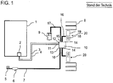
- the part of the pressure medium circuit shown comprises a pressure medium reservoir 6, which is pneumatically connected via a supply line 7 to a first connection 13 of an electrically controllable valve device 10, and also a first parking brake operating unit 2 arranged inside the driver's cab 1, which is electrically connected via lines 3, 4 to a Control unit (not shown) of the electropneumatic valve device 10 is connected.
- the valve device 10 is connected to the spring brake cylinders 18 via compressed air lines 16 .
- the spring-loaded brake cylinders 18 are designed as part of a combination brake cylinder 20, also known as a tristop cylinder, which is first arranged on a wheel axle of the commercial vehicle.
- the combination brake cylinder 20 comprises a diaphragm cylinder 19 for actuating the service brake and a spring-loaded brake cylinder 18 to operate the parking brake.
- the spring brake cylinder 18 has a spring chamber with a spring and a pressure chamber which can be pressurized via the compressed air lines 16 or vented.
- the spring-loaded brake cylinders 18 serve as an actuator device to actuate mechanical components of a wheel brake device of a wheel 8, in particular to bring the mechanical components into engagement (spring-loaded brake cylinder vented) and/or out of engagement (spring-loaded brake cylinder vented).
- the pressure medium circuit includes further in figure 1 Components arranged to the left of the pressure medium reservoir 6, such as a four-circuit protection valve, a compressor, a pressure regulator, etc., of which to simplify the illustration in figure 1 only the four-circuit protection valve 5 is shown.
- the electropneumatically controllable valve device 10 used for the electropneumatic control of the ventilation or venting of the spring-loaded brake cylinders 18 is known per se from the prior art and therefore does not have to be described in more detail.
- the electropneumatically controllable valve device 10 has connections 11, 12 for electrical control lines 3, 4, a first connection 13 for a supply line for connecting the valve device 10 to a compressed air supply 6 and further connections 14, 15 for compressed air lines 16 , 17 has.
- Such valve devices 10 can be implemented as a structural unit on which the corresponding connections 11 to 15 are provided in order to connect the electrical and pneumatic lines to the valve device 10 .
- the valve device 10 is designed to apply pressure from the compressed air supply 6 to a compressed air line 16 connected to the connection 14 in the released state of the parking brake device and to vent the compressed air line 16 to engage the parking brake device.
- the specific valve arrangement inside the valve device 10 which is designed in the usual way, is not shown.
- the valve arrangement inside the valve device 10 usually includes a relay valve (not shown), which can be switched into an open position (parking brake when not engaged) and a venting position (parking brake when engaged), with the venting position a working chamber of the internal relay valve, which is connected to the spring brake cylinder 18 via the compressed air line 16, is vented via a vent outlet.
- the parking brake valve device also has a connection 15 which is intended to be connected to a trailer control valve arrangement 9 .
- the valve arrangement 10 is also designed to actuate the parking brake of the utility vehicle and to pressurize the connection 15 in such a way that the brake system of a trailer connected to the trailer control valve arrangement 9 is also actuated.
- FIG. 1 schematically illustrates a first exemplary embodiment of the present invention with a block diagram.
- components with the same reference numerals correspond to the components of figure 1 and are not described separately.
- FIG. 1 illustrated pressure medium circuit comprising the electropneumatically controllable valve device 10
- FIG. 1 illustrated pressure medium circuit comprising the electropneumatically controllable valve device 10
- FIG. 1 illustrated pressure medium circuit comprising the electropneumatically controllable valve device 10
- FIG. 1 illustrated pressure medium circuit comprising the electropneumatically controllable valve device 10
- FIG. 1 illustrated pressure medium circuit comprising the electropneumatically controllable valve device 10
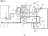
- the parking brake valve device 32 also includes a 3/2-way valve 29, a relay valve 28 and a hand brake valve 30.
- the second connections 14 of the control device 10 are not directly connected to the pressure chambers of the spring brake cylinders 18 . Instead, a compressed air line 21 is attached to only one of the connections 14 and is also connected to a first input 29_1 of the 3/2-way valve 29 .
- the 3/2-way valve 29 also has a second input 29_3 connected to the compressed air source 6 and an output 29_2.
- the additional relay valve 28 is also provided, which has a control input 28_4 connected to the output 29_2 of the control valve 29, a working input 28_1 connected to the compressed air source 6 and a working output 28_2 connected to the two spring brake cylinders 18.
- a second operating element in the form of a hand brake valve 30 is arranged on the compressed air line 22 and between the second input 29_3 of the control valve 29 and the compressed air source 6 .
- the 3/2-way valve 29 serves as a switchable control valve and is designed in such a way that it pneumatically connects that one of its two inputs 29_1, 29_3 to the output 29_2 which is subjected to the lower pressure.
- the 3/2-way valve 29 can thus be operated in what is known as the “select-low operating mode”, so that the smaller of the two input pressures is always present at the output 29_2.
- the relay valve 28 is designed in such a way that when the pressure at the control input 28_4 falls below a predetermined minimum value, the relay valve 28 switches from an open position to a vent position, with the working input 28_1 being connected to the working outlet 28_2 in the open position and the working outlet 28_2 being connected to a Vent output 28_3 of the relay valve 28 is pneumatically connected.
- the handbrake valve 30 is also arranged inside the driver's cab 1, which figure 2 but is not shown. Thus, a section of the line 22 leads to the interior of the driver's cab 1, where the handbrake valve 30 is arranged. It is therefore emphasized that the presentation of figure 2 and the figure 3 is only intended to clarify the connections of the individual air pressure lines with the valve connections, but does not show the actual course of the lines in the vehicle.
- the first and second modes of operation of the electric parking brake device 40 are described below by way of example.
- the compressed air lines 7, 17, 21-27 and the spring brake cylinders 18 are ventilated, i. H. is acted upon by a pressure from the pressure reservoir device 6, so that the air pressure applied to the spring-loaded brake cylinders tensions the spring elements and thereby keeps the mechanical components of the wheel brake disengaged.
- the relay valve 28 is in the open position.
- the parking brake can be engaged in an electrically controlled manner according to the first operating mode.
- the driver can operate the first control unit 2 in the driver's cab.
- the control unit of the valve device 10 is designed in such a way that it vents the compressed air line 21 by controlling the internal valve arrangement of the valve device 10 .
- the venting takes place via an internal relay valve (not shown) of the valve device 10, which releases the compressed air during venting via a vent outlet of the internal relay valve to the environment.
- the compressed air line 21 is pneumatically coupled to the compressed air line 23 via the 3/2-way valve 29, the compressed air line 23 is also vented as a result.
- the relay valve 28 By venting the line 23, which is present at the control input 28_4 of the relay valve 28, the relay valve 28 switches from an open position, in which the working input 28_1 is in the flow position with the working output 28_2, to a venting position, in which the working output 28_2 is connected to a vent output 28_3 of the relay valve 28 is pneumatically connected.
- the second purely pneumatic operating mode is described below. If the vehicle's power supply has failed or if the battery disconnect switch (emergency off switch) has been actuated, the valve device 10 can no longer be controlled electrically. However, the parking brake can be engaged using the pneumatic backup circuit.
- the hand brake valve 30 is actuated in order to vent the compressed air line 22 .
- the venting of the compressed air line 22 causes activation of the 3/2-way valve 29. Since the venting causes the input 29_3 to have a lower pressure than the input 29_1, the 3/2-way valve 29 switches to a position in which the input 29_3 is connected to the output 29_2. Then the compressed air line 23 is also vented.
- venting the compressed air line 23 causes the relay valve 28 to switch to the venting position, so that the compressed air line 24 and thus also the compressed air line 25 are vented, which in turn leads to a venting of the spring brake cylinder 18 and to the construction of a Braking force on the relevant vehicle wheels 8 leads.
- the parking brake is deactivated by actuating the hand brake valve 30 again or by venting the aforementioned compressed air lines together with the spring brake cylinders 18.
- the aforementioned functional principle can also be expanded by installing another 3/2-way valve on the trailer control 9, which is not shown for reasons of clarity.
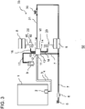
- FIG figure 3 schematically shows a further non-claimed exemplary embodiment of an electric parking brake device 50 with a parking brake valve device 33.
- components with the same reference numbers again correspond to the components of FIG figure 1 or 2 and are not described separately.
- the valve device 10 of figure 3 differs, however, from the valve device 10 of FIG figure 1 , as explained below.
- the second connections 14 and the third connection 15 are of the valve device 10 via the compressed air lines 16 or the compressed air line 17 in a conventional manner as in figure 1 pneumatically connected directly to the spring brake cylinders 18 or to the trailer valve device 9 .
- a special feature of this exemplary embodiment is that a control compressed air line 31 is also provided, which can be vented with the hand brake valve 30 and which is pneumatically connected to a control input or the control chamber of a relay valve (not shown) of the valve device 10 and to the supply line 7 of the compressed air source .
- the valve device 10 includes an internal relay valve via which the compressed air lines 16, 17 can be aerated and vented.
- the compressed air lines 7, 16, 17 and 31 and the spring-loaded brake cylinders 18 are ventilated, i. H. is acted upon by a pressure from the pressure reservoir device 6, so that the air pressure applied to the spring-loaded brake cylinders tensions the spring elements and thereby keeps the mechanical components of the wheel brake disengaged.
- the operating unit 2 in the driver's cab when the power supply is normal, the operating unit 2 in the driver's cab generates an electrical signal when it is actuated, which is transmitted to the control unit 10 via the control lines 3, 4.
- the control unit 10 When this signal is received, the control unit 10 is designed to vent the compressed air lines 16 , 17 and thus the spring-loaded brake cylinders 18 or the line 17 to the trailer valve device 9 via the connections 14 , 15 . In this case, venting takes place via the internal relay valve of the valve arrangement 10, which is switched to a venting position by the control unit of the valve device 10, so that the compressed air can be discharged to the environment.
- a venting of the compressed air line 31 can be initiated by actuating the second actuating element 30, which is also arranged in the driver's cab 2.
- the compressed air line 31 is connected to the control chamber of the internal relay valve of the control unit 10 .
- the venting of the compressed air line 31 causes the pressure in the control chamber of the internal relay valve to drop, as a result of which the working chamber of the relay valve, which is directly connected to the spring brake cylinders 18 via the compressed air lines 16, is also vented.
- a braking force is then built up at the relevant vehicle wheels and the vehicle comes to a standstill or is arrested.
- the brake system of the trailer vehicle can also be actuated in the second operating mode.
- the parking brake is deactivated by actuating the operating element 30 again or by venting the aforementioned compressed air lines together with the spring-loaded brake cylinders 18.
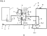
- FIG 4 shows a further exemplary embodiment of an electric parking brake device 60 with a parking brake valve device 34.
- components with the same reference numbers again correspond to the components of the previous figures and are not described separately.
- the second connections 14 of the valve device 10 are again connected via the compressed air lines 16 in a conventional manner as in FIG figure 1 or figure 3 connected directly to the spring brake cylinders 18.
- the parking brake valve device 34 also includes an external relay valve 28 which has a control input 28_4, a working input 28_1 which is pneumatically connected to the compressed air source 6 via the lines 26 and 27 and a working output 28_2 which is pneumatically connected to the two spring brake cylinders 18. Furthermore, a control compressed air line 36 is provided, which can be vented with the muscle-power-operated operating element 30 and which is connected to the control input of the relay valve 28 and to the compressed air source 6 via the compressed air lines 26, 27 and 7.
- the working outlet 28_2 of the relay valve is pneumatically connected to the two spring-loaded brake cylinders 18 via the compressed air line 35, with the compressed air line 35 branching off to the two spring-loaded brake cylinders 18 (lines 35a, 35b) and opening directly into the respective pressure chamber of the spring-loaded brake cylinders 18.
- the lines 35a, 35b can also be pneumatically connected directly to the line 16.
- the relay valve 28 is in turn designed in such a way that if the pressure at the control input 28_4 falls below a predetermined minimum level, the relay valve 28 switches from an open position to a vent position, with the working outlet 28_2 being connected pneumatically to a vent outlet 28_3 of the relay valve in the vent position connected is.
- the first operating mode is analogous to that in figure 3 shown embodiment, in which the spring brake cylinder via the lines 16 and the internal relay valve (not shown) of the valve device 10 are vented.
- venting of the compressed air line 36 is again initiated by actuating the handbrake valve 30 in order to vent the compressed air line 36 .
- This causes the pressure at the control input 28_4 to drop, so that the relay valve 28 switches to the venting position.
- the compressed air line 35 with the sections 35a, 35b and thus the spring brake cylinder 18 is vented.
- the entire supply in the compressed air supply 6 is also slowly vented, limited by the protective function of the four-circuit valve 5 for the other circuits, since the valve device 10, in particular the internal relay valve, is still switched to open.
- FIG 5 schematically shows a further exemplary embodiment of an electric parking brake device 70 with a parking brake valve device 42.
- the exemplary embodiment is a modification of that in FIG figure 2 shown embodiment, in order to be able to actuate a trailer valve device 9 and a trailer brake system (not shown) connected thereto purely pneumatically in the second operating mode.
- components with the same reference numerals correspond to the components of figure 2 and are not described separately.
- the electric parking brake device 70 also has a switchable second 3/2-way valve 41, which has a first input 41_1 connected to the connection 15 of the valve device 10, a second input 41_3, which is connected via the compressed air line 39 to the second input 29_3 of the first 3/ 2-way valve 29 is connected, and has an outlet 41_2 connected to the trailer valve device 9 .
- the second directional valve 41 is designed in such a way that it pneumatically connects that one of its two inputs 41_1, 41_3 to the output 41_2 which is subjected to the lower pressure.
- the trailer valve device or the trailer brake system is aerated and vented in a conventional manner directly via the electropneumatic valve device 10.
- the second 3/2-way valve 41 is switched to an open position. which connects the first input 41_1 to the output 41_2 of the 3/2-way valve 41 as long as the compressed air line 39 connected to the second input 41_3 is pressurized and has not been vented by means of the hand brake valve 30.
- the connection 15 of the electropneumatic valve device 10 is pneumatically connected to the trailer valve device 9 via the first input 41_1 and the output 41_2 of the switchable second control valve 41 .
- the valve device 9 can thus be aerated and vented in a known manner directly via the valve device 10 by appropriate control of its internal relay valve, not shown.
- the electric parking brake device 70 can also be actuated purely pneumatically in the second operating mode.
- the handbrake valve 30 is manually brought into the open position, so that the compressed air line 22 and thus the compressed air line 29 are vented.
- the line pressure at the second input 41_3 of the second 3/2-way valve 41 drops, which activates it and pneumatically couples the second input 41_3 to the output 41_2. Consequently, the compressed air line 38 connected to the outlet 41_2 of the second 3/2-way valve 41 is vented via the second 3/2-way valve 41 and the compressed air lines 39 and 22 .
- the spring brake cylinders are bled in the same way as in connection with figure 2 described.
Landscapes
- Engineering & Computer Science (AREA)
- Transportation (AREA)
- Mechanical Engineering (AREA)
- Braking Systems And Boosters (AREA)
- Valves And Accessory Devices For Braking Systems (AREA)
- Regulating Braking Force (AREA)
Description
- Die Erfindung betrifft eine elektrische Feststellbremsvorrichtung für ein Fahrzeug, vorzugsweise für ein Nutzfahrzeug.
- Nutzfahrzeugbremsanlagen umfassen ein Betriebsbremssystem und ein Parkbremssystem, die zumeist unabhängig voneinander pneumatisch oder elektropneumatisch gesteuert werden. Parkbremssysteme, nachfolgend auch als Feststellbremssysteme bezeichnet, umfassen zumeist Federspeicherbremszylinder, die in ihrem entlüfteten Zustand das Fahrzeug bremsen, während die Parkbremse durch Belüften des Federspeicherbremszylinders gelöst werden kann.
- Nutzfahrzeuge können ferner mit einem Batterietrennschalter, nachfolgend auch als Not-Aus-Trennschalter bezeichnet, ausgestattet werden. Mit einem derartigen Batterietrennschalter können eine oder mehrere Batterien, z. B. im Gefahrenfall, vom angeschlossenen Bordnetz abgetrennt werden. Hierbei tritt das Problem auf, dass nach Betätigung des Not-Aus-Trennschalters oder auch allgemein bei Ausfall der Stromversorgung das Betätigen einer elektrischen Feststellbremse nicht mehr möglich ist.
- Es ist somit eine Aufgabe der Erfindung, eine elektrische Feststellbremse bereitzustellen, mit der Nachteile herkömmlicher elektrischer Feststellbremsen vermieden werden können. Der Erfindung liegt insbesondere die Aufgabe zugrunde, eine elektrische Feststellbremse derart weiterzubilden, dass das Nutzfahrzeug bzw. die Zugkombination auch bei Ausfall der Stromversorgung sicher abgestellt bzw. sicher im Stillstand gehalten werden kann.
- Diese Aufgaben werden durch eine elektrische Feststellbremsvorrichtung gemäß den Merkmalen des Hauptanspruchs gelöst. Vorteilhafte Ausführungsformen und Anwendungen der Erfindung sind Gegenstand der abhängigen Ansprüche und werden in der folgenden Beschreibung unter teilweiser Bezugnahme auf die Figuren näher erläutert.
- Die erfindungsgemäße elektrische Feststellbremsvorrichtung für ein Fahrzeug weist in Übereinstimmung mit dem Stand der Technik eine Feststellbremsventilanordnung und wenigstens einen Federspeicherbremszylinder auf. Der wenigstens eine Federspeicherbremszylinder ist über eine Versorgungsleitung und die Feststellbremsventilanordnung mit einer Druckluftquelle, z. B. einem Druckluftvorrat, verbindbar. Hierbei ist der wenigstens eine Federspeicherbremszylinder im gelösten Zustand der Feststellbremsvorrichtung mit Druck der Druckluftquelle über die Feststellbremsventilanordnung beaufschlagt und im eingelegten Zustand der Feststellbremsvorrichtung über die Feststellbremsventilanordnung mit einer Drucksenke verbindbar. Die Drucksenke kann durch eine Verbindung mit der Umgebungsluft gebildet sein. Die Feststellbremsventilanordnung ist ferner ausgelegt, zum Einlegen des gelösten oder eingelegten Zustands in einer ersten Betriebsart elektropneumatisch gesteuert zu werden.
- Das Dokument
DE 10 2007 051 151 A1 offenbart eine elektropneumatische Feststellbremseinrichtung. Aus der OffenlegungsschriftDE 10 2011 016 740 A1 ist eine elektropneumatische Feststellbremseinrichtung einer Zugfahrzeug-Anhängerkombination zur Durchführung wenigstens einer Feststellbremsfunktion einer Feststellbremse bekannt, wobei ein von einer Bedienperson betätigbares Ventil vorgesehen ist, das bei einer Störung der Elektrik dazu verwendet werden kann, die Anhängerbremse zuzuspannen. - Die Erfindung baut auf diesem Stand der Technik dadurch auf, dass die Feststellbremse in einer zweiten Betriebsart mittels einer rein pneumatischen Backup-Lösung, d. h. ohne Strom, eingelegt und gelöst werden kann. Hierzu weist die Feststellbremsventilanordnung eine muskelkraftbetätigbare Bedieneinheit, nachfolgend auch als zweites Bedienelement bezeichnet, auf und ist ferner dazu ausgelegt, zum Einlegen des gelösten oder eingelegten Zustands in einer zweiten Betriebsart unter Verwendung der muskelkraftbetätigbaren Bedieneinheit rein pneumatisch gesteuert zu werden. Die muskelkraftbetätigbare Bedieneinheit kann ein Handbremsventil, ein Schalter, eine Taste oder ein Druckknopf etc. sein, mittels der manuell eine Druckluftleitung zur Umgebung hin geöffnet werden kann.
- Ein besonderer Vorzug der Erfindung liegt somit darin, dass die Feststellbremse unabhängig vom elektrischen Betriebszustand des Fahrzeugs betätigt werden kann.
- Die Feststellbremsventilanordnung umfasst eine elektropneumatisch steuerbare Ventileinrichtung, die Anschlüsse für elektrische Steuerleitungen, einen ersten Anschluss für eine Versorgungsleitung zur Verbindung der Ventileinrichtung mit der Druckluftquelle und wenigstens einen zweiten Anschluss für eine Druckluftleitung zum Verbinden der elektro-pneumatischen Ventileinrichtung mit einem oder mehreren Federspeicherbremszylindern aufweist.
- Hierbei ist die Ventileinrichtung ausgeführt, im gelösten Zustand der Feststellbremsvorrichtung eine am wenigstens zweiten Anschluss angeschlossene Druckluftleitung mit dem Druck der Druckluftquelle zu beaufschlagen und zum Einlegen der Feststellbremsvorrichtung die an dem wenigstens einen zweiten Anschluss angeschlossene Druckluftleitung zu entlüften.
- Bei Nutzfahrzeugen mit Anhängern kann die elektropneumatisch steuerbare Ventileinrichtung einen dritten Anschluss zum Verbinden der elektropneumatischen Ventileinrichtung mit einer Anhängerventileinrichtung, die die Anhängerbremsanlage steuert, aufweisen. Hierbei kann die Ventileinrichtung wiederum ausgelegt sein, im gelösten Zustand der Feststellbremsvorrichtung eine an dem wenigstens einen dritten Anschluss angeschlossene Druckluftleitung mit Druck der Druckluftquelle zu beaufschlagen und zum Einlegen der Anhängerbremsanlage die am wenigstens einen dritten Anschluss angeschlossene Druckluftleitung zu entlüften.
- Die vorgenannte elektropneumatisch steuerbare Ventileinrichtung ist in einer baulichen Einheit bereitgestellt, so dass die elektropneumatisch steuerbare Ventilanordnung baulich kompakt in einem Gehäuse untergebracht ist.
- Gemäß einer bevorzugten ersten Ausgestaltungsform bildet die vorliegende Erfindung eine derartige elektropneumatisch steuerbare Ventileinrichtung dahingehend weiter, dass ferner ein schaltbares erstes Steuerventil vorgesehen ist, das einen mit dem wenigstens einen zweiten Anschluss der elektropneumatisch steuerbaren Ventileinrichtung pneumatisch verbundenen ersten Eingang, einen mit der Druckluftquelle pneumatisch verbundenen zweiten Eingang und einen Ausgang aufweist.
- Gemäß dieser Ausführungsvariante ist ferner ein in Bezug auf die elektropneumatische Ventileinrichtung externes Relaisventil vorgesehen, das einen mit dem Ausgang des ersten Steuerventils pneumatisch verbundenen Steuereingang, einen mit der Druckluftquelle pneumatisch verbundenen Arbeitseingang und einen mit dem mindestens einen Federspeicherbremszylinder pneumatisch verbundenen Arbeitsausgang aufweist.
- Das muskelkraftbetätigbare Bedienelement ist hierbei zwischen dem zweiten Eingang des ersten Steuerventils und der Druckluftquelle angeordnet, d. h. an einer den zweiten Eingang des ersten Steuerventils und die Druckluftquelle verbindenden Druckluftleitung. Das muskelkraftbetätigbare Bedienelement kann dabei in eine Stellung gebracht werden, in der die Druckluftleitung entlüftet wird.
- Hierbei ist zu erwähnen, dass es sich bei dem vorgenannten Relaisventil nicht um das "interne" Relaisventil der elektropneumatisch steuerbaren Ventileinrichtung handelt, sondern um ein weiteres Relaisventil, nachfolgend auch als externes Relaisventil bezeichnet. Wie weiter unten stehend noch erläutert wird, weisen die bekannten elektropneumatischen Ventileinrichtungen bereits ein internes Relaisventil auf, über das die an dem zweiten Anschluss bzw. den zweiten Anschlüssen und dem dritten Anschluss der elektropneumatischen Ventileinrichtung angeschlossene Druckluftleitung bzw. Druckluftleitungen entlüftet werden können.
- Gemäß einer weiteren Variante der bevorzugten ersten Ausgestaltungsform mit dem schaltbaren ersten Steuerventil und dem dritten Anschluss der Ventileinrichtung kann die elektrische Feststellbremsvorrichtung ein schaltbares zweites Steuerventil aufweisen. Das zweite Steuerventil weist einen mit dem dritten Anschluss der Ventileinrichtung pneumatisch verbundenen ersten Eingang auf. Ein zweiter Eingang des zweiten Steuerventils ist mit der am zweiten Eingang des ersten Steuerventils angeschlossenen und mit der mittels des muskelkraftbetätigbaren Bedienelements entlüftbaren Druckluftleitung pneumatisch verbunden. Ein Ausgang des zweiten Steuerventils ist mit der Anhängerventileinrichtung pneumatisch verbunden. Diese Variante bietet den Vorteil, dass zusätzlich auch die Anhängerbremsanlage über die Anhängerventilanordnung rein pneumatisch, d. h. ohne Strom, betätigt werden kann.
- Eine vorteilhafte Variante sieht vor, dass das erste Steuerventil und/oder das zweite Steuerventil ein 3/2-Wegeventil ist.
- Ferner können das vorgenannte erste Steuerventil und/oder das zweite Steuerventil so ausgelegt sein, dass das Steuerventile jeweils denjenigen seiner beiden Eingänge mit dem Ausgang pneumatisch verbindet, der mit dem kleineren Druck beaufschlagt ist.
- Ferner kann das externe Relaisventil der vorgenannten Ausführungsvarianten so ausgeführt sein, dass bei Unterschreiten eines vorgegebenen Mindestdrucks, mit dem der Steuereingang beaufschlagt ist, das Relaisventil von einer Durchlassstellung, in der der Arbeitseingang mit dem Arbeitsausgang pneumatisch verbunden ist, in eine Entlüftungsstellung schaltet, in der der Arbeitsausgang mit einem Entlüftungsausgang des Relaisventils pneumatisch verbunden ist.
- Die Feststellbremsventilanordnung der vorgenannten Ausgestaltungsformen umfasst somit die elektropneumatisch steuerbare Ventileinrichtung, das schaltbare erste Steuerventil, das externe Relaisventil, und nur gemäß der zusätzlichen Variante zur Steuerung der Anhängerbremsanlage das zusätzliche schaltbare zweite Steuerventil, die über Druckluftleitungen, wie vorstehend beschrieben, miteinander koppelbar sind. Die Feststellbremsventilanordnung kann in einer ersten Betriebsart elektropneumatisch und in einer zweiten Betriebsart rein pneumatisch gesteuert werden.
- Im nichteingelegten Zustand der Feststellbremse des Fahrzeugs sind die Druckluftleitungen und die Federspeicherbremszylinder belüftet bzw. mit einem Druck der Druckluftquelle beaufschlagt.
- Im normalen Betriebsmodus, d. h. bei intakter Stromversorgung, kann durch eine Betätigung einer ersten Bedieneinheit im Fahrerhaus, die über elektrische Steuerleitungen mit der elektropneumatischen Ventileinrichtung verbunden ist, eine Entlüftung der Federspeicherbremszylinder elektropneumatisch eingeleitet werden. Hierbei ist die Ventileinrichtung ausgelegt, bei Eingang eines entsprechenden elektrischen Steuersignals der ersten Bedieneinheit die an dem zweiten Ausgang der Ventileinrichtung angeschlossene Druckluftleitung zu entlüften.
- Dadurch ist der am Ende der entlüfteten Druckluftleitung angeordnete erste Eingang des ersten Steuerventils mit einem kleineren Druck als der zweite Eingang des ersten Steuerventils beaufschlagt, so dass der erste Eingang des ersten Steuerventils mit dem Ausgang des ersten Steuerventils pneumatisch verbunden ist. Dadurch wird die Druckluftleitung, die den Ausgang des schaltbaren ersten Steuerventils mit dem Steuereingang des Relaisventils verbindet, ebenfalls entlüftet.
- Die Entlüftung der am Ausgang des ersten Steuerventils angeschlossenen Druckluftleitung bewirkt somit eine Drucksenkung am Steuereingang des externen Relaisventils, so dass dieses von einer Durchlassstellung in eine Entlüftungsstellung schaltet, in der der Arbeitsausgang des externen Relaisventils mit einem Entlüftungsausgang des externen Relaisventils pneumatisch verbunden ist. Somit wird die am Arbeitsausgang angeschlossene Druckluftleitung, die ferner mit dem wenigstens einen Federzylinder verbunden ist, ebenfalls zur Umgebung hin entlüftet. Folglich werden die Federspeicherbremszylinder mit entlüftet und die Federspeicherbremsen eingelegt.
- Bei der Variante der ersten Ausgestaltungsform mit dem zweiten Steuerventil kann die Anhängerventileinrichtung in der ersten Betriebsart in herkömmlicher Weise direkt über die elektropneumatische Ventileinrichtung belüftet und entlüftet werden. Dies liegt daran, dass das zweite Steuerventil in einer Durchlassstellung geschaltet ist, die den ersten Eingang mit dem Ausgang des zweiten Steuerventils verbindet, solange die am zweiten Eingang des zweiten Steuerventils angeschlossenen Druckluftleitung nicht mittels des muskelkraftbetätigbaren Bedienelements entlüftet wird. In dieser Durchlassstellung ist der dritte Anschluss der elektropneumatischen Ventileinrichtung über den ersten Eingang und den Ausgang des schaltbaren zweiten Steuerventils mit der Anhängerventileinrichtung pneumatisch verbunden und kann somit in bekannter Weise direkt über die Ventileinrichtung elektropneumatisch belüftet und entlüftet werden.
- Nach Betätigung des Batterietrennschalters oder nach Ausfall der Stromversorgung können die Federspeicherbremsen ferner gemäß der zweiten Betriebsart rein pneumatisch eingelegt werden.
- Hierzu wird das muskelkraftbetätigbare zweite Bedienelement manuell in eine geöffnete Stellung gebracht, so dass die Druckluftleitung am zweiten Bedienelement entlüftet wird. Dadurch sinkt der Druck am zweiten Eingang des schaltbaren ersten Steuerventils, wodurch dieses aktiviert wird und den zweiten Eingang mit dem Ausgang pneumatisch koppelt. Folglich wird wiederum die am Ausgang angeschlossene Druckluftleitung entlüftet, die als Steuerleitung für das externe Relaisventil dient, wodurch, wie vorstehend beschrieben, die Entlüftung der Federspeicherbremszylinder über den Entlüftungsausgang des externen Relaisventils eingeleitet wird.
- Bei der Variante der ersten Ausgestaltungsform mit dem zweiten Steuerventil kann die Anhängerventileinrichtung in der zweiten Betriebsart ebenfalls rein pneumatisch gesteuert werden. Gemäß dieser Variante wird wiederum das muskelkraftbetätigbare zweite Bedienelement manuell in die geöffnete Stellung gebracht, so dass die Druckluftleitung am zweiten Bedienelement entlüftet wird. Dadurch sinkt der Druck am zweiten Eingang des schaltbaren ersten Steuerventils und am zweiten Eingang des schaltbaren zweiten Steuerventils, wodurch diese aktiviert werden. Dadurch wird insbesondere der zweite Eingang mit dem Ausgang des zweiten Steuerventils pneumatisch gekoppelt. Folglich wird wiederum die am Ausgang des zweiten Steuerventils angeschlossene Druckluftleitung entlüftet, die das zweite Steuerventil mit der Anhängerventileinrichtung verbindet. Dadurch erfolgt die Entlüftung der Anhängerventileinrichtung über das zweite Steuerventil und die durch das muskelkraftbetätigbare zweite Bedienelement entlüftete Druckluftleitung.
- Ein weiterer Vorzug der vorgenannten Ausgestaltungsform liegt ferner darin, dass durch die beschriebene Erweiterung einer herkömmlichen elektropneumatischen Ventileinrichtung mit dem schaltbaren Steuerventil und dem Relaisventil auf konstruktiv einfach Weise eine pneumatische Backup-Lösung, aufbauend auf herkömmlichen elektropneumatischen Feststellbremsventilanordnungen, ermöglicht wird. Ein weiterer Vorteil ist, dass mit diesem Ansatz auch Nutzfahrzeuge mit einer herkömmlichen elektrischen Feststellbremse nachträglich mit vergleichsweise geringem konstruktivem Aufwand mit einer pneumatischen Backup-Lösung nachrüstbar sind.
- Die Variante dieser Ausgestaltungsform mit dem zweiten Steuerventil bietet den Vorzug, dass auf konstruktiv einfacher Weise ebenfalls die Anhängerventileinrichtung rein pneumatisch gesteuert werden kann.
- Gemäß einer weiteren Ausführungsvariante kann die bekannte elektropneumatisch steuerbare Ventileinrichtung auch nur mittels des externen Relaisventils und ohne erstes und ohne zweites Steuerventil weitergebildet werden, um die zweite rein pneumatische Betriebsart zu ermöglichen. Dadurch kann die pneumatische Backup-Lösung mit verringertem Kostenaufwand realisiert werden.
- Hierzu kann wenigstens eine Versorgungsdruckluftleitung, die den wenigstens einen zweiten Anschluss der Ventileinrichtung mit dem wenigstens einen Federspeicherbremszylinder pneumatisch verbindet, vorgesehen sein. Ferner ist wiederum ein in Bezug auf die elektropneumatische Ventileinrichtung externes Relaisventil vorgesehen, das einen Steuereingang, einen mit der Druckluftquelle verbundenen Arbeitseingang und einen mit dem mindestens einen Federspeicherbremszylinder pneumatisch verbundenen Arbeitsausgang aufweist. Weiterhin ist eine Steuerdruckluftleitung vorgesehen, die mit dem muskelkraftbetätigbaren Bedienelement entlüftbar ist und die mit dem Steuereingang des Relaisventils und mit der Druckluftquelle, vorzugsweise über die Versorgungsleitung der Druckluftquelle, verbunden ist.
- Der Arbeitsausgang des externen Relaisventils ist über eine Druckluftleitung mit dem wenigstens einen Federspeicherbremszylinder pneumatisch verbunden ist, wobei die Druckluftleitung in eine Druckkammer oder in die Versorgungsdruckluftleitung des wenigstens einen Federspeicherbremszylinders münden kann.
- Bei dieser Ausführungsvariante erfolgt die Belüftung und Entlüftung der Federspeicherbremszylinder in der ersten Betriebsart in herkömmlicher Weise direkt über die elektropneumatische Ventileinrichtung. Dies liegt daran, dass die zweiten Anschlüsse der elektropneumatischen Ventileinrichtung direkt über Druckluftleitungen mit den Druckkammern der Federspeicherbremszylinder pneumatisch gekoppelt sind, so dass zum Belüften der zweite Ausgang mit Druck des Druckvorrats beaufschlagt wird und zum Entlüften der zweite Anschluss über die elektropneumatische Ventileinrichtung mit einer Drucksenke, z. B. mit der Umgebungsluft, verbunden wird.
- Gemäß der zweiten, rein pneumatischen Betriebsart wird eine Entlüftung des Steuereingangs des Relaisventils durch eine Betätigung des zweiten muskelkraftbetätigbaren Bedienelements eingeleitet, so dass das Relaisventil in die Entlüftungsstellung schaltet. In der Entlüftungsstellung werden die Federspeicherbremszylinder über die Druckluftleitung, die den Arbeitsausgang des Relaisventils mit den Federspeicherbremszylindern pneumatisch verbindet, entlüftet.
- Zur zusätzlichen Steuerung einer Anhängerbremsanlage gemäß der ersten und der zweiten Betriebsart kann ferner eine Versorgungsdruckluftleitung vorgesehen sein, die den dritten Anschluss der elektropneumatischen Ventileinrichtung mit der Anhängerventileinrichtung pneumatisch verbindet.
- Gemäß einer weiteren nicht beanspruchten Ausführungsvariante kann durch entsprechende Anpassung einer herkömmlichen elektropneumatischen Ventilanordnung auf das Vorsehen eines zusätzlichen schaltbaren Steuerventils sowie des zusätzlichen externen Relaisventils gemäß der vorstehend beschriebenen Variante vermieden werden.
- Stattdessen sieht die Ausführungsvariante vor, dass eine Steuerdruckluftleitung bereitgestellt wird, die mit dem muskelkraftbetätigbaren Bedienelement entlüftbar ist und die mit einem Steuereingang eines Relaisventils der Ventileinrichtung und mit der Versorgungsleitung der Druckluftquelle verbunden ist. Bei dieser Ausführungsvariante wird somit die Tatsache ausgenutzt, dass bekannte elektropneumatische Ventileinrichtungen bereits ein internes Relaisventil aufweisen, über das die an dem zweiten Anschluss bzw. den zweiten Anschlüssen der elektropneumatischen Ventileinrichtung angeschlossene Druckluftleitung bzw. Druckluftleitungen entlüftet werden können.
- Hierbei wird vorteilhafterweise an der baulichen Einheit, z. B. am Gehäuse, der elektropneumatischen Ventileinrichtung ein weiterer Anschluss bereitgestellt, über den die Steuerdruckluftleitung an den Steuereingang des internen Relaisventils der Ventileinrichtung pneumatisch angeschlossen werden kann.
- Gemäß dieser Variante ist ferner wenigstens eine Versorgungsdruckluftleitung vorgesehen, die den wenigstens einen zweiten Anschluss der Ventileinrichtung mit dem wenigstens einen Federspeicherbremszylinder pneumatisch verbindet.
- Gemäß dieser Ausführungsvariante kann die elektropneumatische Ventileinrichtung somit über ihre zweiten Anschlüsse direkt mit den Federspeicherbremszylindern verbunden werden, wie dies auch der Fall bei einer herkömmlichen elektrischen Federspeicherfeststellbremsvorrichtung ohne pneumatische Backup-Lösung der Fall wäre.
- Gemäß der vorgenannten Ausführungsvariante kann das interne Relaisventil der elektropneumatischen Ventileinrichtung so ausgelegt sein, dass bei Unterschreiten eines vorgegebenen Mindestdrucks, mit dem der Steuereingang des Relaisventils der Ventileinrichtung beaufschlagt ist, das Relaisventil von einer Durchlassstellung in eine Entlüftungsstellung schaltet, wobei in der Entlüftungsstellung eine an dem zweiten Anschluss der Ventileinrichtung angeschlossene Druckluftleitung mit einem Entlüftungsausgang des Relaisventils pneumatisch verbunden ist.
- Gemäß dieser Ausführungsvariante ist somit der Steuereingang des internen Relaisventils der Ventileinrichtung so ausgeführt, dass dieser sowohl elektrisch über die elektrischen Anschlüsse der Ventileinrichtung als auch rein pneumatisch über die zusätzliche Steuerdruckluftleitung, die mit dem Steuereingang des Relaisventils pneumatisch verbunden ist, steuerbar ist.
- So kann mittels Betätigung des muskelkraftbetätigbaren Bedienelements eine Entlüftung der Steuerdruckluftleitung eingeleitet werden, die mit der Steuerkammer des internen Relaisventils verbunden ist. Daraufhin wird die Arbeitskammer des internen Relaisventils, die direkt mit den Federspeicherbremszylindern über Druckluftleitungen verbunden ist, ebenfalls entlüftet. Daraufhin wird an den Fahrzeugrädern, an denen die Federspeicherbremszylinder angeordnet sind, eine Bremskraft aufgebaut, und das Fahrzeug kommt zum Stehen bzw. wird festgesetzt.
- Eine an dem dritten Anschluss der elektropneumatische steuerbaren Ventileinrichtung angeschlossenen Druckluftleitung zum Anschluss an die Anhängerventileinrichtung kann dann in analoger Weise zu den Druckluftleitungen, die an den zweiten Anschlüssen angeschlossen sind, ebenfalls wahlweise elektropneumatisch oder rein pneumatisch belüftet und entlüftet werden.
- Gemäß der Erfindung ist das muskelkraftbetätigbare Bedienelement im Fahrerhaus eines Nutzfahrzeugs angeordnet, so dass der Fahrer auch nach Unterbrechung der Stromversorgung die Feststellbremse, ohne aus dem Fahrerhaus aussteigen zu müssen, einlegen kann. Dies ist besonders vorteilhaft, falls sich das Fahrzeug gerade an einer Steigung befindet.
- Ein weiterer Aspekt der Erfindung betrifft ein Nutzfahrzeug mit einer elektrischen Feststellbremsvorrichtung nach einem der vorhergehenden Aspekte.
- Weitere Einzelheiten und Vorteile der Erfindung werden im Folgenden unter Bezug auf die beigefügten Zeichnungen beschrieben. Es zeigen:
- Figur 1
- eine herkömmliche, aus dem Stand der Technik bekannte elektrische Feststellbremsvorrichtung;
- Figur 2
- eine elektrische Feststellbremsvorrichtung gemäß einem ersten Ausführungsbeispiel;
- Figur 3
- eine elektrische Feststellbremsvorrichtung gemäß einem zweiten nicht-beanspruchten Ausführungsbeispiel;
- Figur 4
- eine elektrische Feststellbremsvorrichtung gemäß einem dritten Ausführungsbeispiel; und
- Figur 5
- eine elektrische Feststellbremsvorrichtung gemäß einem vierten Ausführungsbeispiel.
- Zunächst wird anhand von
Figur 1 schematisch mit einem Blockschaltbild eine aus dem Stand der Technik bekannte elektrische Feststellbremsanlage erläutert. Die Feststellbremsanlage steuert die Feststellbremse über einen Druckmittelkreis. - Der in der
Figur 1 dargestellte Teil des Druckmittelkreises umfasst einen Druckmittelvorratsbehälter 6, der über eine Versorgungsleitung 7 pneumatisch mit einem ersten Anschluss 13 einer elektrisch steuerbaren Ventileinrichtung 10 verbunden ist, und ferner eine im Inneren des Fahrerhauses 1 angeordnete erste Parkbremsbedieneinheit 2, die über Leitungen 3, 4 elektrisch mit einer Steuereinheit (nicht gezeigt) der elektropneumatischen Ventileinrichtung 10 verbunden ist. - Die Ventileinrichtung 10 ist über Druckluftleitungen 16 mit den Federspeicherbremszylindern 18 verbunden. Im vorliegenden Beispiel sind die Federspeicherbremszylinder 18 als Teil eines Kombi-Bremszylinders 20, auch Tristop-Zylinder genannt, ausgebildet, der jeweils an einer Radachse des Nutzfahrzeugs angeordnet erst. Der Kombi-Bremszylinder 20 umfasst einen Membranzylinder 19 zur Betätigung der Betriebsbremse und einen Federspeicherbremszylinder 18 zur Betätigung der Feststellbremse. Der Federspeicherbremszylinder 18 weist eine Federkammer mit einer Feder auf sowie eine Druckkammer, die über die Druckluftleitungen 16 mit Druck beaufschlagt oder aber entlüftet werden kann. Die Federspeicherbremszylinder 18 dienen als Aktoreinrichtung, um mechanische Bauteile einer Radbremseinrichtung eines Rades 8 zu betätigen, insbesondere um die mechanischen Bauteile in Eingriff (Federspeicherbremszylinder entlüftet) und/oder außer Eingriff (Federspeicherbremszylinder belüftet) zu bringen.
- Der Druckmittelkreis umfasst weitere in
Figur 1 links vom Druckmittelvorratsbehälter 6 angeordnete Komponenten, wie beispielsweise ein Vierkreisschutzventil, einen Kompressor, einen Druckregler, etc., von denen zur Vereinfachung der Darstellung inFigur 1 nur das Vierkreisschutzventil 5 dargestellt ist. - Die zur elektropneumatischen Steuerung der Belüftung bzw. Entlüftung der Federspeicherbremszylinder 18 eingesetzte elektropneumatisch steuerbare Ventileinrichtung 10 ist an sich aus dem Stand der Technik bekannt und muss deshalb nicht näher beschrieben werden. An dieser Stelle ist lediglich zu erwähnen, dass die elektropneumatisch steuerbare Ventileinrichtung 10 Anschlüsse 11, 12 für elektrische Steuerleitungen 3, 4, einen ersten Anschluss 13 für eine Versorgungsleitung zur Verbindung der Ventileinrichtung 10 mit einem Druckluftvorrat 6 und weitere Anschlüsse 14, 15 für Druckluftleitungen 16, 17 aufweist. Derartige Ventileinrichtungen 10 können als bauliche Einheit realisiert sein, an der die entsprechenden Anschlüsse 11 bis 15 vorgesehen sind, um die elektrischen und pneumatischen Leitungen an der Ventileinrichtung 10 anzuschließen.
- Die Ventileinrichtung 10 ist ausgeführt, im gelösten Zustand der Feststellbremsvorrichtung eine an dem Anschluss 14 angeschlossene Druckluftleitung 16 mit Druck des Druckluftvorrats 6 zu beaufschlagen und zum Einlegen der Feststellbremsvorrichtung die Druckluftleitung 16 zu entlüften. Zur Vereinfachung der Darstellung ist die konkrete Ventilanordnung im Innern der Ventileinrichtung 10, die in üblicher Weise ausgeführt ist, nicht dargestellt. Hierbei ist lediglich festzustellen, dass die Ventilanordnung im Innern der Ventileinrichtung 10 üblicherweise ein Relaisventil (nicht dargestellt) umfasst, das in eine Durchlassstellung (Feststellbremse im nicht eingelegten Zustand) und in eine Entlüftungsstellung (Feststellbremse im eingelegten Zustand) schaltbar ist, wobei in der Entlüftungsstellung eine Arbeitskammer des internen Relaisventils, die über die Druckluftleitung 16 mit dem Federspeicherbremszylinder 18 verbunden ist, über einen Entlüftungsausgang entlüftet wird.
- Im vorliegenden Beispiel weist die Feststellbremsventileinrichtung ferner einen Anschluss 15 auf, der dazu vorgesehen ist, mit einer Anhängersteuerventilanordnung 9 verbunden zu werden. Hierbei ist die Ventilanordnung 10 ferner dazu ausgelegt, die Feststellbremse des Nutzfahrzeugs zu betätigen und den Anschluss 15 so mit Druck zu beaufschlagen, dass die Bremsanlage eines an die Anhängersteuerventilanordnung 9 angeschlossenen Anhängers ebenfalls betätigt wird.
-
Figur 2 illustriert schematisch mit einem Blockschaltbild ein erstes Ausführungsbeispiel der vorliegenden Erfindung. Hierbei entsprechen Komponenten mit gleichen Bezugszeichen den Komponenten derFigur 1 und werden nicht gesondert beschrieben. - Eine Besonderheit dieses Ausführungsbeispiels liegt darin, dass der in
Figur 1 dargestellte Druckmittelkreis, umfassend die elektropneumatisch steuerbare Ventileinrichtung 10, mittels zusätzlicher Komponenten zu einer Feststellbremsventileinrichtung 32 so erweitert und abgewandelt wird, dass eine zweite rein pneumatische Betriebsart der Feststellbremse 40 ermöglicht wird. - Die Feststellbremsventileinrichtung 32 umfasst neben der Ventileinrichtung 10 ferner ein 3/2-Wegeventil 29, ein Relaisventil 28 und ein Handbremsventil 30. Hierzu sind im Unterschied zur
Figur 1 die zweiten Anschlüsse 14 der Steuereinrichtung 10 nicht unmittelbar mit den Druckkammern der Federspeicherbremszylinder 18 verbunden. Stattdessen wird an nur einem der Anschlüsse 14 eine Druckluftleitung 21 angebracht, die ferner mit einem ersten Eingang 29_1 des 3/2-Wegeventils 29 verbunden ist. Das 3/2-Wegeventil 29 weist ferner einen mit der Druckluftquelle 6 verbundenen zweiten Eingang 29_3 und einen Ausgang 29_2 auf. - Ferner ist das weitere Relaisventil 28 vorgesehen, das einen mit dem Ausgang 29_2 des Steuerventils 29 verbundenen Steuereingang 28_4, einen mit der Druckluftquelle 6 verbundenen Arbeitseingang 28_1 und einen mit den beiden Federspeicherbremszylindern 18 verbundenen Arbeitsausgang 28_2 aufweist.
- Ferner ist ein zweites Bedienelement in Form eines Handbremsventils 30 an der Druckluftleitung 22 und zwischen dem zweiten Eingang 29_3 des Steuerventils 29 und der Druckluftquelle 6 angeordnet. Das 3/2-Wegeventil 29 dient als schaltbares Steuerventil und ist so ausgelegt, dass es denjenigen seiner beiden Eingänge 29_1, 29_3 mit dem Ausgang 29_2 pneumatisch verbindet, der mit dem kleineren Druck beaufschlagt ist. Das 3/2-Wegeventil 29 kann somit im sogenannten "Select-Low-Betriebsmodus" betrieben werden, so dass immer der kleinere der beiden Eingangsdrücke am Ausgang 29_2 anliegt.
- Das Relaisventil 28 ist hierbei so ausgelegt, dass bei Unterschreiten eines vorgegebenen Mindestdrucks am Steuereingang 28_4 das Relaisventil 28 von einer Durchlassstellung in eine Entlüftungsstellung schaltet, wobei in der Durchlassstellung der Arbeitseingang 28_1 mit dem Arbeitsausgang 28_2 verbunden ist und in der Entlüftungsstellung der Arbeitsausgang 28_2 mit einem Entlüftungsausgang 28_3 des Relaisventils 28 pneumatisch verbunden ist.
- Das Handbremsventil 30 ist ebenfalls im Inneren des Fahrerhauses 1 angeordnet, was in
Figur 2 aber nicht dargestellt ist. So führt ein Teilabschnitt der Leitung 22 bis ins Innere des Fahrerhauses 1, wo das Handbremsventil 30 angeordnet ist. Es wird daher betont, dass die Darstellung derFigur 2 und derFigur 3 nur die Verbindungen der einzelnen Luftdruckleitungen mit den Ventilanschlüssen verdeutlichen soll, nicht jedoch den tatsächlichen Verlauf der Leitungen im Fahrzeug darstellt. - Nachfolgend wird beispielhaft die erste und zweite Betriebsart der elektrischen Feststellbremsvorrichtung 40 beschrieben.
- Befindet sich das Fahrzeug in einem Zustand mit nicht eingelegter Feststellbremse, beispielsweise im Fahrmodus, dann sind die Druckluftleitungen 7, 17, 21 - 27 und die Federspeicherbremszylinder 18 belüftet, d. h. mit einem Druck der Druckvorratsvorrichtung 6 beaufschlagt, so dass der an den Federspeicherbremszylindern anliegende Luftdruck die Federelemente spannt und dadurch die mechanischen Komponenten der Radbremse außer Eingriff hält. Das Relaisventil 28 befindet sich in der Durchlassstellung.
- Solange die Stromversorgung des Bordnetzes intakt ist, kann die Feststellbremse gemäß der ersten Betriebsart elektrisch gesteuert eingelegt werden. Hierzu kann der Fahrer die erste Bedieneinheit 2 im Fahrerhaus betätigen. Die Steuereinheit der Ventileinrichtung 10 ist so ausgeführt, dass diese durch Ansteuerung der internen Ventilanordnung der Ventileinrichtung 10 die Druckluftleitung 21 entlüftet. Die Entlüftung erfolgt hierbei, wie vorstehend bereits erwähnt, über ein internes Relaisventil (nicht dargestellt) der Ventileinrichtung 10, das die Druckluft beim Entlüften über einen Entlüftungsausgang des internen Relaisventils an die Umgebung abgibt.
- Da die Druckluftleitung 21 über das 3/2-Wegeventil 29 mit der Druckluftleitung 23 pneumatisch gekoppelt ist, wird die Druckluftleitung 23 dadurch ebenfalls entlüftet.
- Durch die Entlüftung der Leitung 23, die am Steuereingang 28_4 des Relaisventils 28 anliegt, schaltet das Relaisventil 28 von einer Durchlassstellung, in der der Arbeitseingang 28_1 mit dem Arbeitsausgang 28_2 in Durchflussstellung ist, in eine Entlüftungsstellung, in der der Arbeitsausgang 28_2 mit einem Entlüftungsausgang 28_3 des Relaisventils 28 pneumatisch verbunden ist.
- Dadurch wird die Druckluftleitung 24 und die daran angeschlossene Druckluftleitung 25 entlüftet. Über die Druckluftleitungen 24, 25, die direkt mit dem Federspeicherbremszylinder 18 verbunden sind, werden somit die Federspeicherbremszylinder 18 entlüftet, was ein Einlegen der Feststellbremse bewirkt.
- Nachfolgend wird die zweite rein pneumatische Betriebsart beschrieben. Ist die Stromversorgung des Fahrzeugs ausgefallen oder wurde der Batterietrennschalter (Not-Aus-Schalter) betätigt, kann die Ventileinrichtung 10 nicht mehr elektrisch gesteuert werden. Die Feststellbremse kann jedoch mittels des pneumatischen Backupkreises eingelegt werden.
- Hierzu wird das Handbremsventil 30 betätigt, um die Druckluftleitung 22 zu entlüften. Die Entlüftung der Druckluftleitung 22 bewirkt eine Aktivierung des 3/2-Wegeventils 29. Da aufgrund der Entlüftung der Eingang 29_3 mit einem kleineren Druck als der Eingang 29_1 beaufschlagt ist, schaltet das 3/2-Wegeventil 29 in eine Stellung, in der der Eingang 29_3 mit dem Ausgang 29_2 verbunden ist. Daraufhin wird die Druckluftleitung 23 ebenfalls entlüftet. Wie vorstehend für die erste Betriebsart bereits beschrieben, bewirkt eine Entlüftung der Druckluftleitung 23 ein Umschalten des Relaisventils 28 in die Entlüftungsstellung, so dass die Druckluftleitung 24 und damit auch die Druckluftleitung 25 entlüftet werden, was wiederum zu einer Entlüftung der Federspeicherbremszylinder 18 und zum Aufbau einer Bremskraft an den relevanten Fahrzeugrädern 8 führt.
- Die Deaktivierung der Feststellbremse erfolgt durch erneutes Betätigen des Handbremsventils 30 bzw. durch Belüften der vorgenannten Druckluftleitungen nebst Federspeicherbremszylindern 18.
- Das vorgenannte Funktionsprinzip ist ferner durch die Installation eines weiteren 3/2-Wegeventils auf die Anhängersteuerung 9 erweiterbar, was aus Übersichtsgründen nicht dargestellt ist.
-
Figur 3 zeigt schematisch ein weiteres nicht-beanspruchtes Ausführungsbeispiel einer elektrischen Feststellbremsvorrichtung 50 mit einer Feststellbremsventileinrichtung 33. Hierbei entsprechen Komponenten mit gleichen Bezugszeichen wiederum den Komponenten derFigur 1 oder2 und werden nicht gesondert beschrieben. Die Ventileinrichtung 10 derFigur 3 unterscheidet sich jedoch von der Ventileinrichtung 10 derFigur 1 , wie nachfolgend erläutert wird. - Bei dieser Ausführungsvariante sind die zweiten Anschlüsse 14 bzw. der dritten Anschluss 15 der Ventileinrichtung 10 über die Druckluftleitungen 16 bzw. die Druckluftleitung 17 in herkömmlicher Weise wie in
Figur 1 direkt mit den Federspeicherbremszylindern 18 bzw. mit der Anhängerventileinrichtung 9 pneumatisch verbunden. - Eine Besonderheit dieses Ausführungsbeispiel liegt darin, das ferner eine Steuerdruckluftleitung 31 vorgesehen ist, die mit dem Handbremsventil 30 entlüftbar ist und die mit einem Steuereingang bzw. der Steuerkammer eines Relaisventils (nicht gezeigt) der Ventileinrichtung 10 und mit der Versorgungsleitung 7 der Druckluftquelle pneumatisch verbunden ist. Es wurde vorstehend bereits erwähnt, dass die Ventileinrichtung 10 ein internes Relaisventil umfasst, über das die Druckluftleitungen 16, 17 belüftet und entlüftet werden können.
- Befindet sich das Fahrzeug in einem Zustand mit nicht eingelegter Feststellbremse, beispielsweise im Fahrstellung, dann sind die Druckluftleitungen 7, 16, 17, und 31 und die Federspeicherbremszylinder 18 belüftet, d. h. mit einem Druck der Druckvorratsvorrichtung 6 beaufschlagt, so dass der an den Federspeicherbremszylindern anliegende Luftdruck die Federelemente spannt und dadurch die mechanischen Komponenten der Radbremse außer Eingriff hält.
- Gemäß der ersten Betriebsart erzeugt bei normaler Stromversorgung die Bedieneinheit 2 im Fahrerhaus bei Betätigung ein elektrisches Signal, das über die Steuerleitungen 3, 4 an die Steuereinheit 10 übertragen wird. Bei Empfang dieses Signals ist die Steuereinheit 10 ausgelegt, über die Anschlüsse 14, 15 die Druckluftleitungen 16, 17 und damit die Federspeicherbremszylinder 18 bzw. die Leitung 17 zur Anhängerventileinrichtung 9 zu entlüften. Hierbei erfolgt die Entlüftung über das interne Relaisventil der Ventilanordnung 10, das von der Steuereinheit der Ventileinrichtung 10 in eine Entlüftungsstellung geschaltet wird, so dass die Druckluft an die Umgebung abgegeben werden kann.
- Bei einer zweiten Betriebsart, z. B. nach Unterbrechung einer Stromversorgung, kann mittels einer Betätigung des zweiten Betätigungselements 30, das ebenfalls im Fahrerhaus 2 angeordnet ist, eine Entlüftung der Druckluftleitung 31 eingeleitet werden. Die Druckluftleitung 31 ist, wie vorstehend beschrieben, mit der Steuerkammer des internen Relaisventils der Steuereinheit 10 verbunden. Die Entlüftung der Druckluftleitung 31 bewirkt eine Absenkung des Drucks in der Steuerkammer des internen Relaisventils, wodurch die Arbeitskammer des Relaisventils, die direkt mit den Federspeicherbremszylindern 18 über die Druckluftleitungen 16 verbunden ist, ebenfalls entlüftet wird. An den relevanten Fahrzeugrädern wird daraufhin eine Bremskraft aufgebaut, und das Fahrzeug kommt zum Stehen bzw. wird festgesetzt.
- Ist die Arbeitskammer des internen Relaisventils in der Entlüftungsstellung nicht nur mit den Anschlüssen 16, sondern auch mit dem Anschluss 17 für das Anhängerventil verbunden, kann in der zweiten Betriebsart auch die Bremsanlage des Anhängerfahrzeugs betätigt werden.
- Eine Deaktivierung der Feststellbremse erfolgt durch erneutes Betätigen des Bedienelements 30 bzw. durch Belüften der vorgenannten Druckluftleitungen nebst Federspeicherbremszylindern 18.
-
Figur 4 zeigt schematisch ein weiteres Ausführungsbeispiel einer elektrischen Feststellbremsvorrichtung 60 mit einer Feststellbremsventileinrichtung 34. Hierbei entsprechen Komponenten mit gleichen Bezugszeichen wiederum den Komponenten der vorherigen Figuren und werden nicht gesondert beschrieben. - Bei dieser Ausführungsvariante sind die zweiten Anschlüsse 14 der Ventileinrichtung 10 über die Druckluftleitungen 16 wiederum in herkömmlicher Weise wie in
Figur 1 oderFigur 3 direkt mit den Federspeicherbremszylindern 18 verbunden. - Die Feststellbremsventileinrichtung 34 umfasst neben der elektropneumatischen Ventileinrichtung 10 ferner ein hierzu externes Relaisventil 28, das einen Steuereingang 28_4, einen mit der Druckluftquelle 6 über die Leitungen 26 und 27 pneumatisch verbundenen Arbeitseingang 28_1 und einen mit den beiden Federspeicherbremszylindern 18 pneumatisch verbundenen Arbeitsausgang 28_2 aufweist. Ferner ist eine Steuerdruckluftleitung 36 vorgesehen, die mit dem muskelkraftbetätigbaren Bedienelement 30 entlüftbar ist und die mit dem Steuereingang des Relaisventils 28 und mit der Druckluftquelle 6 über die Druckluftleitungen 26, 27 und 7 verbunden ist.
- Der Arbeitsausgang 28_2 des Relaisventils ist über die Druckluftleitung 35 mit den beiden Federspeicherbremszylindern 18 pneumatisch verbunden, wobei die Druckluftleitung 35 sich zu den beiden Federspeicherbremszylindern 18 hin verzweigt (Leitungen 35a, 35b) und direkt in die jeweilige Druckkammer der Federspeicherbremszylinder 18 mündet. Die Leitungen 35a, 35b können alternativ auch direkt mit der Leitung 16 pneumatisch verbunden werden.
- Hierbei ist das Relaisventil 28 wiederum so ausgelegt, dass es bei Unterschreiten eines vorgegebenen Mindestdrucks, mit dem der Steuereingang 28_4 beaufschlagt ist, das Relaisventil 28 von einer Durchlassstellung in eine Entlüftungsstellung schaltet, wobei in der Entlüftungsstellung der Arbeitsausgang 28_2 mit einem Entlüftungsausgang 28_3 des Relaisventils pneumatisch verbunden ist.
- Die erste Betriebsart erfolgt analog zu dem in
Figur 3 gezeigten Ausführungsbeispiel, in dem die Federspeicherbremszylinder über die Leitungen 16 und das interne Relaisventil (nicht gezeigt) der Ventileinrichtung 10 entlüftet werden. - Bei der zweiten, rein pneumatischen Betriebsart wird eine Entlüftung der Druckluftleitung 36 wiederum durch eine Betätigung des Handbremsventils 30 eingeleitet, um die Druckluftleitung 36 zu entlüften. Dies führt zu einem Absinken des Drucks am Steuereingang 28_4, so dass das Relaisventil 28 in die Entlüftungsstellung schaltet. In der Entlüftungsstellung wird die Druckluftleitung 35 mit den Abschnitten 35a, 35b und damit die Federspeicherbremszylinder 18 entlüftet. Hierbei erfolgt zudem eine langsame Entlüftung des gesamten Vorrats im Druckluftvorrat 6, eingeschränkt durch die Schutzfunktion des Vierkreisventils 5 für die anderen Kreise, da die Ventileinrichtung 10, insbesondere das interne Relaisventil, noch auf Durchlass geschaltet ist.
-
Figur 5 zeigt schematisch ein weiteres Ausführungsbeispiel einer elektrischen Feststellbremsvorrichtung 70 mit einer Feststellbremsventileinrichtung 42. Das Ausführungsbeispiel ist eine Abwandlung des in derFigur 2 gezeigten Ausführungsbeispiels, um zusätzlich eine Anhängerventileinrichtung 9 und eine daran angeschlossene Anhängerbremsanlage (nicht gezeigt) in der zweiten Betriebsart rein pneumatisch betätigen zu können. Hierbei entsprechen Komponenten mit gleichen Bezugszeichen den Komponenten derFigur 2 und werden nicht gesondert beschrieben. - Die elektrische Feststellbremsvorrichtung 70 weist zusätzlich ein schaltbares zweites 3/2-Wegeventill 41 auf, das einen mit dem Anschluss 15 der Ventileinrichtung 10 verbundenen ersten Eingang 41_1, einen zweiten Eingang 41_3, der über die Druckluftleitung 39 mit dem zweiten Eingang 29_3 des ersten 3/2-Wegeventils 29 verbunden ist, und einen mit der Anhängerventileinrichtung 9 verbundenen Ausgang 41_2 aufweist.
- Wie das erste 3/2-Wegeventil 29 ist das zweite Wegeventil 41 so ausgelegt, dass es denjenigen seiner beiden Eingänge 41_1, 41_3 mit dem Ausgang 41_2 pneumatisch verbindet, der mit dem kleineren Druck beaufschlagt ist.
- In der ersten, elektropneumatischen Betriebsart erfolgt die Belüftung und Entlüftung der Anhängerventileinrichtung bzw. der Anhängerbremsanlage in herkömmlicher Weise direkt über die elektropneumatische Ventileinrichtung 10. Im Normalbetrieb mit elektrischer Stromversorgung und nicht eingelegter Feststellbremse ist das zweite 3/2-Wegeventil 41 in einer Durchlassstellung geschaltet, die den ersten Eingang 41_1 mit dem Ausgang 41_2 des 3/2-Wegeventils 41 verbindet, solange die am zweiten Eingang 41_3 angeschlossenen Druckluftleitung 39 belüftet ist und nicht mittels des Handbremsventils 30 entlüftet wurde. In dieser Durchlassstellung ist somit der Anschluss 15 der elektropneumatischen Ventileinrichtung 10 über den ersten Eingang 41_1 und den Ausgang 41_2 des schaltbaren zweiten Steuerventils 41 mit der Anhängerventileinrichtung 9 pneumatisch verbunden ist. Die Ventileinrichtung 9 kann somit in bekannter Weise direkt über die Ventileinrichtung 10 durch entsprechende Ansteuerung ihres nicht dargestellten internen Relaisventils belüftet und entlüftet werden.
- Bei Ausfall oder Abschalten der Stromversorgung kann auch die elektrische Feststellbremsvorrichtung 70 in der zweiten Betriebsart rein pneumatisch betätigt werden. Hierbei wird wiederum das Handbremsventil 30 manuell in die geöffnete Stellung gebracht, so dass die Druckluftleitung 22 und damit die Druckluftleitung 29 entlüftet werden. Dadurch sinkt der Leitungsdruck am zweiten Eingang 41_3 des zweiten 3/2-Wegeventils 41, wodurch diese aktiviert wird und den zweiten Eingang 41_3 mit dem Ausgang 41_2 pneumatisch koppelt. Folglich wird die am Ausgang 41_2 des zweiten 3/2-Wegeventils 41 angeschlossene Druckluftleitung 38 über das zweite 3/2-Wegeventil 41 und die Druckluftleitungen 39 und 22 entlüftet. Die Entlüftung der Federspeicherbremszylinder erfolgt auf dieselbe Weise wie in Zusammenhang mit
Figur 2 beschrieben. - Obwohl die Erfindung unter Bezugnahme auf bestimmte Ausführungsbeispiele beschrieben worden ist, ist eine Vielzahl von Varianten und Abwandlungen möglich, die ebenfalls von dem Erfindungsgedanken Gebrauch machen und deshalb in den Schutzbereich fallen. Folglich soll die Erfindung nicht auf die offenbarten bestimmten Ausführungsbeispiele begrenzt sein, sondern die Erfindung soll alle Ausführungsbeispiele umfassen, die in den Bereich der beigefügten Patentansprüche fallen.
-
- 1
- Fahrerhaus
- 2
- Bedieneinheit für erste Betriebsart
- 3, 4
- Elektrische Steuerleitungen
- 5
- Vierkreisschutzventil
- 6
- Druckmittelvorratsbehälter
- 7
- Vorratsleitung
- 8
- Fahrzeugrad
- 9
- Anhängersteuerventileinrichtung
- 10
- Elektropneumatisch steuerbare Ventileinrichtung
- 11, 12
- Anschlüsse für elektrische Leitungen
- 13
- Anschluss für Versorgungsleitung
- 14, 15
- Anschlüsse für Druckluftleitungen
- 16, 17
- Druckluftleitungen
- 18
- Federspeicherbremszylinder
- 19
- Membranzylinder
- 20
- Kombi-Bremszylinder
- 21-27, 35, 35a, 35b, 36-39
- Druckluftleitungen
- 28
- Relaisventil
- 28_1
- Arbeitseingang
- 28_2
- Arbeitsausgang
- 28_3
- Entlüftungsausgang
- 28_4
- Steuereingang
- 29,41
- 3/2-Wegeventil
- 29_1, 41_1
- Erster Eingang
- 29_2, 41_2
- Ausgang
- 29_3, 41_3
- Zweiter Eingang
- 30
- Muskelkraftbetätigbares Betätigungselement
- 31
- Druckluftleitung
- 32, 33, 34, 42
- Feststellbremsventilanordnung
- 40, 50, 60, 70
- Elektrische Feststellbremsvorrichtung
Claims (8)
- Elektrische Feststellbremsvorrichtung (40; 50; 60; 70) für ein Fahrzeug, vorzugsweise für ein Nutzfahrzeug, umfassendeine Feststellbremsventilanordnung (32; 33; 34; 42); undwenigstens einen Federspeicherbremszylinder (18), der über eine Versorgungsleitung (7) und die Feststellbremsventilanordnung (32; 33; 34; 42) mit einer Druckluftquelle (6) verbindbar ist, der im gelösten Zustand der Feststellbremsvorrichtung mit Druck der Druckluftquelle (6) über die Feststellbremsventilanordnung beaufschlagt ist und im eingelegten Zustand der Feststellbremsvorrichtung über die Feststellbremsventilanordnung mit einer Drucksenke verbindbar ist;wobei die Feststellbremsventilanordnung dazu ausgelegt ist, zum Einlegen des gelösten oder eingelegten Zustands in einer ersten Betriebsart elektropneumatisch gesteuert zu werden;wobei die Feststellbremsventilanordnung ein im Fahrerhaus (1) eines Nutzfahrzeugs angeordnetes muskelkraftbetätigbares Bedienelement (30) umfasst und weiterhin dazu ausgelegt ist, zum Einlegen des gelösten oder eingelegten Zustands in einer zweiten Betriebsart unter Verwendung des muskelkraftbetätigbaren Bedienelements (30) rein pneumatisch gesteuert zu werden;wobei die Feststellbremsventilanordnung (32; 33; 34) eine elektropneumatisch steuerbare Ventileinrichtung (10) umfasst, aufweisend Anschlüsse (11, 12) für elektrische Steuerleitungen (3,4), einen ersten Anschluss (13) für eine Versorgungsleitung zur Verbindung der Ventileinrichtung (10) mit der Druckluftquelle (6), wenigstens einen zweiten Anschluss (14) für eine Druckluftleitung (16) zum Verbinden der elektro-pneumatischen Ventileinrichtung (10) mit einem oder mehreren Federspeicherbremszylindern (18), wobei die Ventileinrichtung (10) ausgelegt ist, im gelösten Zustand der Feststellbremsvorrichtung eine an dem wenigstens einen zweiten Anschluss (14) angeschlossene Druckluftleitung (16) mit Druck der Druckluftquelle (6) zu beaufschlagen und zum Einlegen der Feststellbremsvorrichtung die am wenigstens einen zweiten Anschluss (14) angeschlossene Druckluftleitung (16) zu entlüften, wobei die elektropneumatisch steuerbare Ventileinrichtung (10) in einer baulichen Einheit bereitgestellt wird;wobei:Variante i):i.a) ein schaltbares erstes Steuerventil (29), das einen mit dem wenigstens einen zweiten Anschluss (14) der Ventileinrichtung (10) verbundenen ersten Eingang (29_1), einen mit der Druckluftquelle (6) verbundenen zweiten Eingang (29_3) und einen Ausgang (29_2) aufweist; undi.b) ein in Bezug auf die elektropneumatische Ventileinrichtung externes Relaisventil (28), das einen mit dem Ausgang (29_2) des ersten Steuerventils (29) verbundenen Steuereingang (28_4), einen mit der Druckluftquelle (6) verbundenen Arbeitseingang (28_1) und einen mit dem mindestens einen Federspeicherbremszylinder (18) verbundenen Arbeitsausgang (28_2) aufweist; wobei das muskelkraftbetätigbare Bedienelement (30) die Druckluftleitung (22) entlüften kann und es zwischen dem zweiten Eingang (29_3) des ersten Steuerventils und der Druckluftquelle (6) angeordnet ist;oder Variante ii):ii.a) wenigstens eine Versorgungsdruckluftleitung (16), die den wenigstens einen zweiten Anschluss (14) der Ventileinrichtung (10) mit dem wenigstens einen Federspeicherbremszylinder (18) pneumatisch verbindet; undii.b) ein in Bezug auf die elektropneumatische Ventileinrichtung externes Relaisventil (28), das einen Steuereingang (28_4), einen mit der Druckluftquelle (6) verbundenen Arbeitseingang (28_1) und einen mit dem mindestens einen Federspeicherbremszylinder (18) pneumatisch verbundenen Arbeitsausgang (28_2) aufweist; undii.c) eine Steuerdruckluftleitung (36), die mit dem muskelkraftbetätigbaren Bedienelement (30) entlüftbar ist und die mit dem Steuereingang des Relaisventils (28) und mit der Druckluftquelle (6), vorzugsweise über die Versorgungsleitung (7) der Druckluftquelle (6), verbunden ist.
- Elektrische Feststellbremsvorrichtung (40; 50; 60; 70) nach Anspruch 1, dadurch gekennzeichnet,
dass die elektropneumatisch steuerbare Ventileinrichtung (10) einen dritten Anschluss (15) zum Verbinden der elektropneumatischen Ventileinrichtung (10) mit einer Anhängerventileinrichtung (9) aufweist, wobei die Ventileinrichtung (10) ausgelegt ist, im gelösten Zustand der Feststellbremsvorrichtung eine an dem wenigstens einen dritten Anschluss (15) angeschlossene Druckluftleitung (17) mit Druck der Druckluftquelle (6) zu beaufschlagen und zum Einlegen der Feststellbremsvorrichtung die am wenigstens einen dritten Anschluss (15) angeschlossene Druckluftleitung (17) zu entlüften. - Elektrische Feststellbremsvorrichtung (70) nach Anspruch 1 oder 2 gemäß Variante i), gekennzeichnet durch ein schaltbares zweites Steuerventil (41), das einen mit dem dritten Anschluss (15) der Ventileinrichtung (10) verbundenen ersten Eingang (41_1), einen mit der am zweiten Eingang (29_3) des ersten Steuerventils (29) angeschlossenen und mittels des muskelkraftbetätigbaren Bedienelements (30) entlüftbaren Druckluftleitung (22) verbundenen zweiten Eingang (41_3) und einen mit der Anhängerventileinrichtung (9) verbundenen Ausgang (41_2) aufweist.
- Elektrische Feststellbremsvorrichtung (40; 70) nach einem der vorherigen Ansprüche gemäß Variante i), dadurch gekennzeichnet,(a) dass das erste Steuerventil (29) und/oder das zweite Steuerventil (41) ein 3/2-Wegeventil ist; und/oder(b) dass das erste Steuerventil (29) und/oder das zweite Steuerventil (41) so ausgelegt ist, dass es denjenigen seiner beiden Eingänge mit dem Ausgang pneumatisch verbindet, der mit dem kleineren Druck beaufschlagt ist.
- Elektrische Feststellbremsvorrichtung (60) nach Anspruch 1 oder 2 gemäß Variante ii), dadurch gekennzeichnet, dass der Arbeitsausgang (28_2) des Relaisventils über eine Druckluftleitung (35) mit dem wenigstens einen Federspeicherbremszylinder (18) pneumatisch verbunden ist, wobei die Druckluftleitung (35) in eine Druckkammer oder in die Versorgungsdruckluftleitung (16) des wenigstens einen Federspeicherbremszylinders (18) mündet.
- Elektrische Feststellbremsvorrichtung (60) nach einem der Ansprüche 1, 2 oder 5 gemäß Variante ii), gekennzeichnet durch eine Versorgungsdruckluftleitung (17), die den dritten Anschluss (15) der Ventileinrichtung (10) mit der Anhängerventileinrichtung (9) pneumatisch verbindet.
- Elektrische Feststellbremsvorrichtung (40; 60; 70) nach einem der Ansprüche 1 bis 6 gemäß der Varianten i) oder ii), dadurch gekennzeichnet, dass das Relaisventil (28) so ausgelegt ist, dass es bei Unterschreiten eines vorgegebenen Mindestdrucks, mit dem der Steuereingang (28_4) beaufschlagt ist, das Relaisventil (28) von einer Durchlassstellung in eine Entlüftungsstellung schaltet, wobei in der Entlüftungsstellung der Arbeitsausgang (28_2) mit einem Entlüftungsausgang (28_3) des Relaisventils pneumatisch verbunden ist.
- Nutzfahrzeug mit einer elektrischen Feststellbremsvorrichtung (40; 50; 60; 70) nach einem der vorhergehenden Ansprüche.
Applications Claiming Priority (1)
| Application Number | Priority Date | Filing Date | Title |
|---|---|---|---|
| DE102014004933.7A DE102014004933A1 (de) | 2014-04-05 | 2014-04-05 | Elektrische Federspeicher-Feststellbremse |
Publications (4)
| Publication Number | Publication Date |
|---|---|
| EP2927067A2 EP2927067A2 (de) | 2015-10-07 |
| EP2927067A3 EP2927067A3 (de) | 2016-01-13 |
| EP2927067B1 EP2927067B1 (de) | 2018-01-10 |
| EP2927067B2 true EP2927067B2 (de) | 2022-12-14 |
Family
ID=52465154
Family Applications (1)
| Application Number | Title | Priority Date | Filing Date |
|---|---|---|---|
| EP15000276.4A Active EP2927067B2 (de) | 2014-04-05 | 2015-01-29 | Elektrische Federspeicher-Feststellbremse |
Country Status (5)
| Country | Link |
|---|---|
| EP (1) | EP2927067B2 (de) |
| CN (1) | CN105035056B (de) |
| BR (1) | BR102015003671B1 (de) |
| DE (1) | DE102014004933A1 (de) |
| RU (1) | RU2692514C2 (de) |
Families Citing this family (8)
| Publication number | Priority date | Publication date | Assignee | Title |
|---|---|---|---|---|
| DE102016010460A1 (de) * | 2016-08-31 | 2018-03-01 | Wabco Gmbh | Elektronisch steuerbares pneumatisches Bremssystem in einem Nutzfahrzeug sowie Verfahren zum elektronischen Steuern eines pneumatischen Bremssystems in einem Nutzfahrzeug |
| DE102016011390A1 (de) * | 2016-09-21 | 2018-03-22 | Wabco Gmbh | Parkbrems-Ventileinrichtung zur Ansteuerung einer Federspeicher-Feststellbremse |
| DE102017009307A1 (de) * | 2017-10-07 | 2019-04-11 | Wabco Gmbh | Parkbrems-Ventileinrichtung |
| WO2020038585A1 (en) * | 2018-08-24 | 2020-02-27 | Wabco Europe Bvba | Pneumatic brake control module components |
| DE102018122953A1 (de) * | 2018-09-19 | 2020-03-19 | Knorr-Bremse Systeme für Nutzfahrzeuge GmbH | Elektronische Parkbremseinrichtung und Verfahren zum Betrieb einer elektronischen Parkbremseinrichtung |
| DE102018127822A1 (de) * | 2018-11-07 | 2020-05-07 | Knorr-Bremse Systeme für Nutzfahrzeuge GmbH | Ventilanordnung und ein Verfahren zur Drucksteuerung |
| DE102019118896A1 (de) * | 2019-07-12 | 2021-01-14 | Knorr-Bremse Systeme für Nutzfahrzeuge GmbH | Parkbremseinrichtung |
| US11820341B2 (en) * | 2020-10-01 | 2023-11-21 | Valcrum, Llc | Electrically modulated air brake |
Citations (1)
| Publication number | Priority date | Publication date | Assignee | Title |
|---|---|---|---|---|
| DE102007051151A1 (de) † | 2007-04-23 | 2008-11-06 | Knorr-Bremse Systeme für Nutzfahrzeuge GmbH | Nutzfahrzeugbremsanlage |
Family Cites Families (21)
| Publication number | Priority date | Publication date | Assignee | Title |
|---|---|---|---|---|
| DE3527907A1 (de) * | 1985-08-03 | 1987-02-12 | Wabco Westinghouse Fahrzeug | Elektrisch gesteuerte druckmittel-bremsanlage |
| DE19609222A1 (de) | 1996-03-09 | 1997-09-11 | Bosch Gmbh Robert | Anhängersteuerventil für eine Druckluftbremsanlage für Kraftfahrzeuge |
| US5794739A (en) * | 1996-06-14 | 1998-08-18 | Westinghouse Air Brake Company | Pneumatic pressure operated parking brake for a railway vehicle brake system |
| RU2145555C1 (ru) * | 1998-01-22 | 2000-02-20 | Открытое акционерное общество "КАМАЗ" | Пневматическая тормозная система транспортного средства |
| DE10132493C2 (de) * | 2001-07-05 | 2003-05-15 | Knorr Bremse Systeme | Druckmittelbetätigte Bremsanlage einer Zugfahrzeug-Anhänger-Kombination |
| DE10233018A1 (de) | 2002-07-20 | 2004-01-29 | Iveco Magirus Ag | Verfahren und Bremsvorrichtung zur Feststell-Bremsung von Fahrzeugen , insbesondere Lastkraftwagen |
| DE10336611A1 (de) | 2003-08-08 | 2005-03-03 | Wabco Gmbh & Co.Ohg | Druckmittelbetriebene Bremsanlage für ein Fahrzeug |
| DE102005019479B3 (de) | 2005-04-27 | 2007-01-18 | Haldex Brake Products Gmbh | Anhängerbremsventil für einen Kraftfahrzeug-Anhänger |
| DE102006036748A1 (de) * | 2006-08-05 | 2008-02-07 | Wabco Gmbh | Elektrisch gesteuerte Bremsanlage |
| DE102007042316B4 (de) * | 2006-11-16 | 2010-01-07 | Knorr-Bremse Systeme für Nutzfahrzeuge GmbH | Elektronisches Bremssystem für ein Nutzfahrzeug und Verfahren zum Steuern eines elektronischen Bremssystems |
| DE102007016335A1 (de) * | 2007-04-04 | 2008-10-09 | Wabco Gmbh | Feststellbremseinrichtung eines Fahrzeuges mit Notlösefunktion sowie Verfahren zum Betreiben einer derartigen Feststellbremseinrichtung |
| DE102007053766B3 (de) | 2007-11-12 | 2009-03-19 | Haldex Brake Products Gmbh | Steueranlage für Kraftfahrzeug-Anhänger mit Betriebsbremse, Feststellbremse und Luftfederung |
| DE102008007877B3 (de) | 2008-02-06 | 2009-11-26 | Knorr-Bremse Systeme für Nutzfahrzeuge GmbH | Parkbremseinrichtung |
| DE102008014547A1 (de) | 2008-03-15 | 2009-09-17 | Wabco Gmbh | Bremsanlage für ein Fahrzeug |
| DE102008047631A1 (de) * | 2008-09-17 | 2010-03-25 | Knorr-Bremse Systeme für Nutzfahrzeuge GmbH | Verfahren zum Betreiben eines Feststellbremsmoduls im Defektfall und zum Ausführen des Verfahrens geeignetes Feststellbremsmodul |
| DE102009059816B3 (de) | 2009-12-21 | 2011-04-28 | Knorr-Bremse Systeme für Nutzfahrzeuge GmbH | Elektrisch betätigbares Feststellbremssystem und Verfahren zum Steuern eines elektrisch betätigbaren Feststellbremssystems |
| DE102010021909A1 (de) * | 2010-05-28 | 2011-12-01 | Knorr-Bremse Systeme für Nutzfahrzeuge GmbH | Verfahren zur Steuerung einer Bremsanlage eines Fahrzeugs mit elektronisch geregeltem Hinterachsbremskreis und pneumatisch gesteuertem Vorderachsbremskreis |
| WO2012049649A1 (en) * | 2010-10-13 | 2012-04-19 | Agricultural And Industrial Mechanisation Group (Proprietary) Limited | Fail-safe brake system |
| DE102010050578A1 (de) * | 2010-11-05 | 2012-05-10 | Wabco Gmbh | System mit Ventileinrichtung für eine pneumatisch betriebene Bremsanlage, Ventileinrichtung, Bremsbestätigungseinrichtung, Anhängersteuerventileinrichtung und Einrichtung zur Steuerung für das System, Bremsanlage, Fahrzeug, Verwendung einer Komponente und Verfahren zum Umrüsten einer Bremsanlage |
| DE102011016740B4 (de) * | 2011-04-12 | 2017-05-11 | Knorr-Bremse Systeme für Nutzfahrzeuge GmbH | Elektro-pneumatische Feststellbremseinrichtung eines Fahrzeugs |
| DE102012013959A1 (de) | 2012-07-13 | 2014-05-15 | Knorr-Bremse Systeme für Nutzfahrzeuge GmbH | Elektrisch betätigbares Feststellbremssystem für eine pneumatische Bremsanlage und Verfahren zum Betreiben eines elektrisch betätigbaren Feststellbremssystems |
-
2014
- 2014-04-05 DE DE102014004933.7A patent/DE102014004933A1/de not_active Ceased
-
2015
- 2015-01-29 EP EP15000276.4A patent/EP2927067B2/de active Active
- 2015-02-20 BR BR102015003671-0A patent/BR102015003671B1/pt active IP Right Grant
- 2015-03-30 RU RU2015111514A patent/RU2692514C2/ru active
- 2015-04-03 CN CN201510156502.8A patent/CN105035056B/zh active Active
Patent Citations (1)
| Publication number | Priority date | Publication date | Assignee | Title |
|---|---|---|---|---|
| DE102007051151A1 (de) † | 2007-04-23 | 2008-11-06 | Knorr-Bremse Systeme für Nutzfahrzeuge GmbH | Nutzfahrzeugbremsanlage |
Also Published As
| Publication number | Publication date |
|---|---|
| EP2927067A3 (de) | 2016-01-13 |
| RU2692514C2 (ru) | 2019-06-25 |
| DE102014004933A1 (de) | 2015-10-08 |
| EP2927067A2 (de) | 2015-10-07 |
| RU2015111514A (ru) | 2016-10-20 |
| CN105035056A (zh) | 2015-11-11 |
| CN105035056B (zh) | 2019-08-06 |
| RU2015111514A3 (de) | 2018-11-01 |
| EP2927067B1 (de) | 2018-01-10 |
| BR102015003671B1 (pt) | 2022-05-03 |
| BR102015003671A2 (pt) | 2018-02-27 |
Similar Documents
| Publication | Publication Date | Title |
|---|---|---|
| EP2927067B2 (de) | Elektrische Federspeicher-Feststellbremse | |
| EP2939892B1 (de) | Elektrische Feststellbremse für ein Fahrzeug | |
| EP3600996B1 (de) | Integriertes anhängersteuermodul (tcv) mit externer elektropneumatischer handbremseinheit (eph) | |
| EP3755589B1 (de) | Elektropneumatische ausrüstung eines fahrzeugs | |
| EP3112230B1 (de) | Feststellbremsmodul, bremsanlage und fahrzeug damit sowie verfahren zum betreiben einer feststellbremseinrichtung mit einem solchen modul | |
| EP3145769B1 (de) | Elektropneumatische bremssteuereinrichtung mit automatischer entlüftung der federspeicherbremse bei stromausfall | |
| EP4058334B1 (de) | Elektropneumatisches steuermodul | |
| EP4396052B1 (de) | Betriebssichere parkbremsventileinheit mit einem bypassventil | |
| EP3292030B1 (de) | Vorrichtung zum steuern einer bremsanlage für ein nutzfahrzeug und bremsanlage | |
| EP2055542B1 (de) | Druckmittelbetätigte Bremseinrichtung eines Zugfahrzeugs mit einem gegenläufige Drücke für Anhängerbremsen erzeugenden Festellbremsmodul | |
| EP2939891B1 (de) | Elektrische Feststellbremse | |
| EP2190706B1 (de) | Ventilanordnung zur steuerung einer bremsanlage eines anhängerfahrzeugs | |
| EP2133250B1 (de) | Parkbremsventilanordnung für ein Bremssystem eines Nutzfahrzeuges | |
| DE102017005979A1 (de) | Elektro-Pneumatische Handbremse (EPH) mit integrierten TCV (skandinavische Ansteuerung | |
| EP3307594B1 (de) | Pneumatische bremsanlage für ein anhängefahrzeug | |
| DE102013106260A1 (de) | Elektropneumatische Bremsanlage | |
| EP3307595A1 (de) | Verfahren zum regeln von bremsen in einem anhängefahrzeug | |
| EP3507148B1 (de) | Pneumatische bremsanlage für ein anhängefahrzeug | |
| EP2082935B1 (de) | Bremseinrichtung eines wenigstens zweiachsigen, eine gelenkte Vorderachse aufweisenden Anhängerfahrzeugs einer Zugfahrzeug-Anhängerkombination | |
| EP2154041B1 (de) | Druckmittelbetätigte Bremsvorrichtung für Kraftfahrzeuge | |
| DE102019117650A1 (de) | Elektropneumatisches Handbrems-System für Nutzfahrzeuge mit Federspeicher-Feststellbremsen | |
| DE102023136451A1 (de) | Betriebsbremsentlüftungseinheit für eine betriebssichere Feststellbremsanordnung | |
| EP3112231A1 (de) | Feststellbremsmodul, bremsanlage und fahrzeug damit sowie verfahren zum betreiben einer feststellbremseinrichtung mit einem solchen modul | |
| EP2094547B1 (de) | Feststellbremsvorrichtung mit druckluftversorgungsleitungen für eine feststellbremse | |
| WO2020058030A1 (de) | Elektronische parkbremseinrichtung und verfahren zum betrieb einer elektronischen parkbremseinrichtung |
Legal Events
| Date | Code | Title | Description |
|---|---|---|---|
| PUAI | Public reference made under article 153(3) epc to a published international application that has entered the european phase |
Free format text: ORIGINAL CODE: 0009012 |
|
| AK | Designated contracting states |
Kind code of ref document: A2 Designated state(s): AL AT BE BG CH CY CZ DE DK EE ES FI FR GB GR HR HU IE IS IT LI LT LU LV MC MK MT NL NO PL PT RO RS SE SI SK SM TR |
|
| AX | Request for extension of the european patent |
Extension state: BA ME |
|
| PUAL | Search report despatched |
Free format text: ORIGINAL CODE: 0009013 |
|
| AK | Designated contracting states |
Kind code of ref document: A3 Designated state(s): AL AT BE BG CH CY CZ DE DK EE ES FI FR GB GR HR HU IE IS IT LI LT LU LV MC MK MT NL NO PL PT RO RS SE SI SK SM TR |
|
| AX | Request for extension of the european patent |
Extension state: BA ME |
|
| RIC1 | Information provided on ipc code assigned before grant |
Ipc: B60T 13/68 20060101AFI20151208BHEP Ipc: B60T 13/38 20060101ALI20151208BHEP Ipc: B60T 13/04 20060101ALI20151208BHEP |
|
| 17P | Request for examination filed |
Effective date: 20160701 |
|
| GRAP | Despatch of communication of intention to grant a patent |
Free format text: ORIGINAL CODE: EPIDOSNIGR1 |
|
| STAA | Information on the status of an ep patent application or granted ep patent |
Free format text: STATUS: GRANT OF PATENT IS INTENDED |
|
| INTG | Intention to grant announced |
Effective date: 20170922 |
|
| GRAS | Grant fee paid |
Free format text: ORIGINAL CODE: EPIDOSNIGR3 |
|
| GRAA | (expected) grant |
Free format text: ORIGINAL CODE: 0009210 |
|
| STAA | Information on the status of an ep patent application or granted ep patent |
Free format text: STATUS: THE PATENT HAS BEEN GRANTED |
|
| AK | Designated contracting states |
Kind code of ref document: B1 Designated state(s): AL AT BE BG CH CY CZ DE DK EE ES FI FR GB GR HR HU IE IS IT LI LT LU LV MC MK MT NL NO PL PT RO RS SE SI SK SM TR |
|
| REG | Reference to a national code |
Ref country code: CH Ref legal event code: EP Ref country code: AT Ref legal event code: REF Ref document number: 962035 Country of ref document: AT Kind code of ref document: T Effective date: 20180115 |
|
| REG | Reference to a national code |
Ref country code: FR Ref legal event code: PLFP Year of fee payment: 4 |
|
| REG | Reference to a national code |
Ref country code: IE Ref legal event code: FG4D Free format text: LANGUAGE OF EP DOCUMENT: GERMAN |
|
| REG | Reference to a national code |
Ref country code: NL Ref legal event code: FP |
|
| REG | Reference to a national code |
Ref country code: DE Ref legal event code: R096 Ref document number: 502015002783 Country of ref document: DE |
|
| REG | Reference to a national code |
Ref country code: SE Ref legal event code: TRGR |
|
| PG25 | Lapsed in a contracting state [announced via postgrant information from national office to epo] |
Ref country code: ES Free format text: LAPSE BECAUSE OF FAILURE TO SUBMIT A TRANSLATION OF THE DESCRIPTION OR TO PAY THE FEE WITHIN THE PRESCRIBED TIME-LIMIT Effective date: 20180110 Ref country code: HR Free format text: LAPSE BECAUSE OF FAILURE TO SUBMIT A TRANSLATION OF THE DESCRIPTION OR TO PAY THE FEE WITHIN THE PRESCRIBED TIME-LIMIT Effective date: 20180110 Ref country code: FI Free format text: LAPSE BECAUSE OF FAILURE TO SUBMIT A TRANSLATION OF THE DESCRIPTION OR TO PAY THE FEE WITHIN THE PRESCRIBED TIME-LIMIT Effective date: 20180110 Ref country code: NO Free format text: LAPSE BECAUSE OF FAILURE TO SUBMIT A TRANSLATION OF THE DESCRIPTION OR TO PAY THE FEE WITHIN THE PRESCRIBED TIME-LIMIT Effective date: 20180410 Ref country code: LT Free format text: LAPSE BECAUSE OF FAILURE TO SUBMIT A TRANSLATION OF THE DESCRIPTION OR TO PAY THE FEE WITHIN THE PRESCRIBED TIME-LIMIT Effective date: 20180110 Ref country code: CY Free format text: LAPSE BECAUSE OF FAILURE TO SUBMIT A TRANSLATION OF THE DESCRIPTION OR TO PAY THE FEE WITHIN THE PRESCRIBED TIME-LIMIT Effective date: 20180110 |
|
| PG25 | Lapsed in a contracting state [announced via postgrant information from national office to epo] |
Ref country code: IS Free format text: LAPSE BECAUSE OF FAILURE TO SUBMIT A TRANSLATION OF THE DESCRIPTION OR TO PAY THE FEE WITHIN THE PRESCRIBED TIME-LIMIT Effective date: 20180510 Ref country code: RS Free format text: LAPSE BECAUSE OF FAILURE TO SUBMIT A TRANSLATION OF THE DESCRIPTION OR TO PAY THE FEE WITHIN THE PRESCRIBED TIME-LIMIT Effective date: 20180110 Ref country code: LV Free format text: LAPSE BECAUSE OF FAILURE TO SUBMIT A TRANSLATION OF THE DESCRIPTION OR TO PAY THE FEE WITHIN THE PRESCRIBED TIME-LIMIT Effective date: 20180110 Ref country code: GR Free format text: LAPSE BECAUSE OF FAILURE TO SUBMIT A TRANSLATION OF THE DESCRIPTION OR TO PAY THE FEE WITHIN THE PRESCRIBED TIME-LIMIT Effective date: 20180411 Ref country code: BG Free format text: LAPSE BECAUSE OF FAILURE TO SUBMIT A TRANSLATION OF THE DESCRIPTION OR TO PAY THE FEE WITHIN THE PRESCRIBED TIME-LIMIT Effective date: 20180410 Ref country code: PL Free format text: LAPSE BECAUSE OF FAILURE TO SUBMIT A TRANSLATION OF THE DESCRIPTION OR TO PAY THE FEE WITHIN THE PRESCRIBED TIME-LIMIT Effective date: 20180110 |
|
| REG | Reference to a national code |
Ref country code: CH Ref legal event code: PL |
|
| PG25 | Lapsed in a contracting state [announced via postgrant information from national office to epo] |
Ref country code: MT Free format text: LAPSE BECAUSE OF FAILURE TO SUBMIT A TRANSLATION OF THE DESCRIPTION OR TO PAY THE FEE WITHIN THE PRESCRIBED TIME-LIMIT Effective date: 20180110 |
|
| REG | Reference to a national code |
Ref country code: DE Ref legal event code: R026 Ref document number: 502015002783 Country of ref document: DE |
|
| PLBI | Opposition filed |
Free format text: ORIGINAL CODE: 0009260 |
|
| PLAX | Notice of opposition and request to file observation + time limit sent |
Free format text: ORIGINAL CODE: EPIDOSNOBS2 |
|
| PG25 | Lapsed in a contracting state [announced via postgrant information from national office to epo] |
Ref country code: RO Free format text: LAPSE BECAUSE OF FAILURE TO SUBMIT A TRANSLATION OF THE DESCRIPTION OR TO PAY THE FEE WITHIN THE PRESCRIBED TIME-LIMIT Effective date: 20180110 Ref country code: AL Free format text: LAPSE BECAUSE OF FAILURE TO SUBMIT A TRANSLATION OF THE DESCRIPTION OR TO PAY THE FEE WITHIN THE PRESCRIBED TIME-LIMIT Effective date: 20180110 Ref country code: LU Free format text: LAPSE BECAUSE OF NON-PAYMENT OF DUE FEES Effective date: 20180129 Ref country code: EE Free format text: LAPSE BECAUSE OF FAILURE TO SUBMIT A TRANSLATION OF THE DESCRIPTION OR TO PAY THE FEE WITHIN THE PRESCRIBED TIME-LIMIT Effective date: 20180110 Ref country code: MC Free format text: LAPSE BECAUSE OF FAILURE TO SUBMIT A TRANSLATION OF THE DESCRIPTION OR TO PAY THE FEE WITHIN THE PRESCRIBED TIME-LIMIT Effective date: 20180110 |
|
| REG | Reference to a national code |
Ref country code: IE Ref legal event code: MM4A |
|
| REG | Reference to a national code |
Ref country code: BE Ref legal event code: MM Effective date: 20180131 |
|
| 26 | Opposition filed |
Opponent name: KNORR-BREMSE SYSTEME FUER NUTZFAHRZEUGE GMBH Effective date: 20181010 |
|
| PG25 | Lapsed in a contracting state [announced via postgrant information from national office to epo] |
Ref country code: LI Free format text: LAPSE BECAUSE OF NON-PAYMENT OF DUE FEES Effective date: 20180131 Ref country code: DK Free format text: LAPSE BECAUSE OF FAILURE TO SUBMIT A TRANSLATION OF THE DESCRIPTION OR TO PAY THE FEE WITHIN THE PRESCRIBED TIME-LIMIT Effective date: 20180110 Ref country code: SK Free format text: LAPSE BECAUSE OF FAILURE TO SUBMIT A TRANSLATION OF THE DESCRIPTION OR TO PAY THE FEE WITHIN THE PRESCRIBED TIME-LIMIT Effective date: 20180110 Ref country code: BE Free format text: LAPSE BECAUSE OF NON-PAYMENT OF DUE FEES Effective date: 20180131 Ref country code: CZ Free format text: LAPSE BECAUSE OF FAILURE TO SUBMIT A TRANSLATION OF THE DESCRIPTION OR TO PAY THE FEE WITHIN THE PRESCRIBED TIME-LIMIT Effective date: 20180110 Ref country code: CH Free format text: LAPSE BECAUSE OF NON-PAYMENT OF DUE FEES Effective date: 20180131 Ref country code: SM Free format text: LAPSE BECAUSE OF FAILURE TO SUBMIT A TRANSLATION OF THE DESCRIPTION OR TO PAY THE FEE WITHIN THE PRESCRIBED TIME-LIMIT Effective date: 20180110 |
|
| PG25 | Lapsed in a contracting state [announced via postgrant information from national office to epo] |
Ref country code: IE Free format text: LAPSE BECAUSE OF NON-PAYMENT OF DUE FEES Effective date: 20180129 |
|
| PLBB | Reply of patent proprietor to notice(s) of opposition received |
Free format text: ORIGINAL CODE: EPIDOSNOBS3 |
|
| PG25 | Lapsed in a contracting state [announced via postgrant information from national office to epo] |
Ref country code: SI Free format text: LAPSE BECAUSE OF FAILURE TO SUBMIT A TRANSLATION OF THE DESCRIPTION OR TO PAY THE FEE WITHIN THE PRESCRIBED TIME-LIMIT Effective date: 20180110 |
|
| RAP2 | Party data changed (patent owner data changed or rights of a patent transferred) |
Owner name: MAN TRUCK & BUS SE |
|
| GBPC | Gb: european patent ceased through non-payment of renewal fee |
Effective date: 20190129 |
|
| REG | Reference to a national code |
Ref country code: DE Ref legal event code: R081 Ref document number: 502015002783 Country of ref document: DE Owner name: MAN TRUCK & BUS SE, DE Free format text: FORMER OWNER: MAN TRUCK & BUS AG, 80995 MUENCHEN, DE |
|
| PG25 | Lapsed in a contracting state [announced via postgrant information from national office to epo] |
Ref country code: GB Free format text: LAPSE BECAUSE OF NON-PAYMENT OF DUE FEES Effective date: 20190129 |
|
| PG25 | Lapsed in a contracting state [announced via postgrant information from national office to epo] |
Ref country code: TR Free format text: LAPSE BECAUSE OF FAILURE TO SUBMIT A TRANSLATION OF THE DESCRIPTION OR TO PAY THE FEE WITHIN THE PRESCRIBED TIME-LIMIT Effective date: 20180110 |
|
| PG25 | Lapsed in a contracting state [announced via postgrant information from national office to epo] |
Ref country code: PT Free format text: LAPSE BECAUSE OF FAILURE TO SUBMIT A TRANSLATION OF THE DESCRIPTION OR TO PAY THE FEE WITHIN THE PRESCRIBED TIME-LIMIT Effective date: 20180110 |
|
| PG25 | Lapsed in a contracting state [announced via postgrant information from national office to epo] |
Ref country code: MK Free format text: LAPSE BECAUSE OF NON-PAYMENT OF DUE FEES Effective date: 20180110 Ref country code: HU Free format text: LAPSE BECAUSE OF FAILURE TO SUBMIT A TRANSLATION OF THE DESCRIPTION OR TO PAY THE FEE WITHIN THE PRESCRIBED TIME-LIMIT; INVALID AB INITIO Effective date: 20150129 |
|
| REG | Reference to a national code |
Ref country code: AT Ref legal event code: MM01 Ref document number: 962035 Country of ref document: AT Kind code of ref document: T Effective date: 20200129 |
|
| PG25 | Lapsed in a contracting state [announced via postgrant information from national office to epo] |
Ref country code: AT Free format text: LAPSE BECAUSE OF NON-PAYMENT OF DUE FEES Effective date: 20200129 |
|
| PUAH | Patent maintained in amended form |
Free format text: ORIGINAL CODE: 0009272 |
|
| STAA | Information on the status of an ep patent application or granted ep patent |
Free format text: STATUS: PATENT MAINTAINED AS AMENDED |
|
| 27A | Patent maintained in amended form |
Effective date: 20221214 |
|
| AK | Designated contracting states |
Kind code of ref document: B2 Designated state(s): AL AT BE BG CH CY CZ DE DK EE ES FI FR GB GR HR HU IE IS IT LI LT LU LV MC MK MT NL NO PL PT RO RS SE SI SK SM TR |
|
| REG | Reference to a national code |
Ref country code: DE Ref legal event code: R102 Ref document number: 502015002783 Country of ref document: DE |
|
| REG | Reference to a national code |
Ref country code: NL Ref legal event code: FP |
|
| REG | Reference to a national code |
Ref country code: SE Ref legal event code: RPEO |
|
| PGFP | Annual fee paid to national office [announced via postgrant information from national office to epo] |
Ref country code: NL Payment date: 20250127 Year of fee payment: 11 |
|
| PGFP | Annual fee paid to national office [announced via postgrant information from national office to epo] |
Ref country code: DE Payment date: 20250129 Year of fee payment: 11 |
|
| PGFP | Annual fee paid to national office [announced via postgrant information from national office to epo] |
Ref country code: SE Payment date: 20250127 Year of fee payment: 11 |
|
| PGFP | Annual fee paid to national office [announced via postgrant information from national office to epo] |
Ref country code: FR Payment date: 20250127 Year of fee payment: 11 |
|
| PGFP | Annual fee paid to national office [announced via postgrant information from national office to epo] |
Ref country code: IT Payment date: 20250122 Year of fee payment: 11 |