EP2926759A2 - Bras de support destiné à positionner un instrument médical ou un appareil médical - Google Patents
Bras de support destiné à positionner un instrument médical ou un appareil médical Download PDFInfo
- Publication number
- EP2926759A2 EP2926759A2 EP15162185.1A EP15162185A EP2926759A2 EP 2926759 A2 EP2926759 A2 EP 2926759A2 EP 15162185 A EP15162185 A EP 15162185A EP 2926759 A2 EP2926759 A2 EP 2926759A2
- Authority
- EP
- European Patent Office
- Prior art keywords
- components
- segment
- node
- component
- strut
- Prior art date
- Legal status (The legal status is an assumption and is not a legal conclusion. Google has not performed a legal analysis and makes no representation as to the accuracy of the status listed.)
- Granted
Links
- 238000005452 bending Methods 0.000 claims description 11
- 238000004519 manufacturing process Methods 0.000 claims description 11
- 238000005304 joining Methods 0.000 claims description 10
- 239000011265 semifinished product Substances 0.000 claims description 6
- 238000005520 cutting process Methods 0.000 claims description 4
- 238000000034 method Methods 0.000 description 10
- 239000000463 material Substances 0.000 description 8
- 238000003466 welding Methods 0.000 description 6
- 238000004026 adhesive bonding Methods 0.000 description 5
- 238000005476 soldering Methods 0.000 description 5
- 238000003801 milling Methods 0.000 description 4
- 238000005253 cladding Methods 0.000 description 3
- 238000010146 3D printing Methods 0.000 description 2
- 230000005540 biological transmission Effects 0.000 description 2
- 238000010586 diagram Methods 0.000 description 2
- 238000003780 insertion Methods 0.000 description 2
- 230000037431 insertion Effects 0.000 description 2
- 238000003698 laser cutting Methods 0.000 description 2
- 238000003754 machining Methods 0.000 description 2
- 229910052751 metal Inorganic materials 0.000 description 2
- 239000002184 metal Substances 0.000 description 2
- 238000005245 sintering Methods 0.000 description 2
- 230000007704 transition Effects 0.000 description 2
- XLYOFNOQVPJJNP-UHFFFAOYSA-N water Substances O XLYOFNOQVPJJNP-UHFFFAOYSA-N 0.000 description 2
- 241000237942 Conidae Species 0.000 description 1
- 229910000831 Steel Inorganic materials 0.000 description 1
- 229910052782 aluminium Inorganic materials 0.000 description 1
- XAGFODPZIPBFFR-UHFFFAOYSA-N aluminium Chemical compound [Al] XAGFODPZIPBFFR-UHFFFAOYSA-N 0.000 description 1
- 239000003795 chemical substances by application Substances 0.000 description 1
- 230000001419 dependent effect Effects 0.000 description 1
- 238000011161 development Methods 0.000 description 1
- 230000018109 developmental process Effects 0.000 description 1
- 230000003670 easy-to-clean Effects 0.000 description 1
- 230000007613 environmental effect Effects 0.000 description 1
- 238000005530 etching Methods 0.000 description 1
- 230000001788 irregular Effects 0.000 description 1
- 230000002093 peripheral effect Effects 0.000 description 1
- 239000002985 plastic film Substances 0.000 description 1
- 238000004080 punching Methods 0.000 description 1
- 230000000284 resting effect Effects 0.000 description 1
- 238000005096 rolling process Methods 0.000 description 1
- 229910001220 stainless steel Inorganic materials 0.000 description 1
- 239000010935 stainless steel Substances 0.000 description 1
- 239000010959 steel Substances 0.000 description 1
- 230000003313 weakening effect Effects 0.000 description 1
Images


Classifications
-
- B—PERFORMING OPERATIONS; TRANSPORTING
- B25—HAND TOOLS; PORTABLE POWER-DRIVEN TOOLS; MANIPULATORS
- B25J—MANIPULATORS; CHAMBERS PROVIDED WITH MANIPULATION DEVICES
- B25J18/00—Arms
-
- A—HUMAN NECESSITIES
- A61—MEDICAL OR VETERINARY SCIENCE; HYGIENE
- A61B—DIAGNOSIS; SURGERY; IDENTIFICATION
- A61B34/00—Computer-aided surgery; Manipulators or robots specially adapted for use in surgery
- A61B34/30—Surgical robots
-
- A—HUMAN NECESSITIES
- A61—MEDICAL OR VETERINARY SCIENCE; HYGIENE
- A61B—DIAGNOSIS; SURGERY; IDENTIFICATION
- A61B90/00—Instruments, implements or accessories specially adapted for surgery or diagnosis and not covered by any of the groups A61B1/00 - A61B50/00, e.g. for luxation treatment or for protecting wound edges
- A61B90/50—Supports for surgical instruments, e.g. articulated arms
-
- B—PERFORMING OPERATIONS; TRANSPORTING
- B25—HAND TOOLS; PORTABLE POWER-DRIVEN TOOLS; MANIPULATORS
- B25J—MANIPULATORS; CHAMBERS PROVIDED WITH MANIPULATION DEVICES
- B25J17/00—Joints
- B25J17/02—Wrist joints
- B25J17/0241—One-dimensional joints
- B25J17/025—One-dimensional joints mounted in series
-
- B—PERFORMING OPERATIONS; TRANSPORTING
- B25—HAND TOOLS; PORTABLE POWER-DRIVEN TOOLS; MANIPULATORS
- B25J—MANIPULATORS; CHAMBERS PROVIDED WITH MANIPULATION DEVICES
- B25J19/00—Accessories fitted to manipulators, e.g. for monitoring, for viewing; Safety devices combined with or specially adapted for use in connection with manipulators
- B25J19/007—Means or methods for designing or fabricating manipulators
-
- B—PERFORMING OPERATIONS; TRANSPORTING
- B25—HAND TOOLS; PORTABLE POWER-DRIVEN TOOLS; MANIPULATORS
- B25J—MANIPULATORS; CHAMBERS PROVIDED WITH MANIPULATION DEVICES
- B25J9/00—Programme-controlled manipulators
- B25J9/0009—Constructional details, e.g. manipulator supports, bases
-
- A—HUMAN NECESSITIES
- A61—MEDICAL OR VETERINARY SCIENCE; HYGIENE
- A61B—DIAGNOSIS; SURGERY; IDENTIFICATION
- A61B17/00—Surgical instruments, devices or methods, e.g. tourniquets
- A61B2017/00526—Methods of manufacturing
-
- Y—GENERAL TAGGING OF NEW TECHNOLOGICAL DEVELOPMENTS; GENERAL TAGGING OF CROSS-SECTIONAL TECHNOLOGIES SPANNING OVER SEVERAL SECTIONS OF THE IPC; TECHNICAL SUBJECTS COVERED BY FORMER USPC CROSS-REFERENCE ART COLLECTIONS [XRACs] AND DIGESTS
- Y10—TECHNICAL SUBJECTS COVERED BY FORMER USPC
- Y10T—TECHNICAL SUBJECTS COVERED BY FORMER US CLASSIFICATION
- Y10T74/00—Machine element or mechanism
- Y10T74/20—Control lever and linkage systems
- Y10T74/20207—Multiple controlling elements for single controlled element
- Y10T74/20305—Robotic arm
Definitions
- the present invention is directed to a support arm for positioning a medical instrument or medical device, a segment of such a support arm, and a method of manufacturing such a segment.
- An endoscope or other medical instrument that does not need to be moved during a medical procedure, at least temporarily, can be held by a holding arm with lockable joints or degrees of freedom.
- the medical instrument can be moved by motor during the medical procedure.
- Retaining arms for these applications typically have multiple hinges, each allowing pivoting about one or more axes.
- a medical holding arm should be as stiff as possible in order to keep a medical instrument or medical device as immovable as possible in the case of locked joints or stationary drives, even when external forces are applied.
- a medical support arm should have a low mass to a movement with low forces and with less To enable performance.
- the arm should be mechanically robust, easy to maintain, inexpensive to produce, easy to assemble and easy to clean and completely.
- An object of the present invention is to provide an improved segment for a support arm, an improved support arm for positioning a medical instrument or a medical device, and an improved method of manufacturing a segment for a support arm.
- a segment for a holding arm for positioning a medical instrument or a medical device comprises a plurality of node components and a strut which rigidly interconnects two of the plurality of node components, wherein the strut comprises planar components, wherein the planar components are joined together.
- a node component is designed in particular for the articulated mechanical connection of the segment to a further segment or another part of a holding arm.
- a node component is designed in particular as part of a radial and thrust bearing.
- a node component comprises a bearing shell for a sliding or roller bearing.
- the node components are produced in particular by milling and / or other machining processes or in a 3D printing process or in a sintering process.
- each node component may be provided and configured to directly or indirectly (for example via a shaft connecting two node components) with a hydraulic, pneumatic, electromotive or other actuator for moving the segment relative to another, adjacent segment or a other part of the support arm to be connected.
- the strut is only subjected to tension and pressure, so it must - as an entire component - take up no or essentially no other forces and moments. Due to the spatial shape of the strut is formed in the strut at tensile or compressive load, however, in particular a bending moment.
- the strut comprises in particular two or three flat components.
- the flat components of the strut are each cut and bent in particular from sheet metal or other plate-shaped semifinished product. If the strut comprises two flat components, these are in particular joined together so that an at least approximately T-shaped cross section is formed. If the strut comprises three flat components, these are in particular joined together so that an approximately I-shaped cross section is formed. Alternatively, the strut may comprise four flat components that are joined together to form an approximately trapezoidal cross-section.
- the flat components are in particular joined together by welding, soldering, gluing or otherwise cohesively.
- the flat components can be positively and / or non-positively joined by means of one or more bolts, screws, rivets or snap-in connections.
- the production of a segment for a holding arm with struts can enable a cost-effective production with high mechanical strength. Building a segment with multiple node components and multiple struts can provide good accessibility of all components inside the segment.
- the segment can in particular be clad with a component in the form of a lateral surface of a cylinder or a cone.
- one of the flat components has the shape of a section of a cylinder jacket or a conical jacket.
- the planar component has the shape of a substantially helical strip-shaped section of a lateral surface of a circular cylinder or of an elliptical cylinder or of another cylinder.
- the planar component for example, the shape of a section of a cone sheath, in particular a conical spiral or conical helix or more generally a loxodrome on.
- the segment comprises a plurality of struts, in particular each one of the flat components of each strut has the shape of a substantially helically stripe-shaped section of a lateral surface of a cylinder or the shape of a loxodrome on a cone.
- these two-dimensional Components of two struts opposite helical or have the shape of two opposing Loxodrome.
- the axis of symmetry of the cylinder jacket or the conical jacket is in particular parallel to the longitudinal axis of the segment.
- the longitudinal axis of the segment is the straight line through the centers of the ball joints.
- the longitudinal axis of the segment is the straight line through the centers of shafts in the pivot joints at the ends of the segment.
- one of the two-dimensional components may have the shape of a section of a conical jacket, in particular a circular cone jacket.
- the axis of symmetry of the conical surface or the straight line through the tip and center of the base is in particular parallel to the longitudinal axis of the segment.
- one of the flat components has a pin which engages in a corresponding recess in another of the flat components.
- one or more pins are provided on one or both longitudinal sides of a planar component which connects two further planar components web-shaped.
- the pin or pins are in particular each cuboid or substantially cuboid.
- a pin on a flat component, which engages in a recess on another planar component can form a non-positive connection between the flat components, which can be reinforced, for example, materially.
- a pin on a flat component which engages in a recess on another planar component, allow transmission of shear forces between the two flat components.
- snap hooks, resilient structures or other features may be provided on one of the planar components, which allow a latching connection.
- To secure the connection of two flat components may also holes, recesses or cavities may be provided for inserting split pins.
- a screw connection for example, a rivet connection or a connection can be provided by means of a bolt.
- a bolt can connect two flat components in particular by a projection, a nose or a tab on one of the two flat components is guided by a corresponding slot in the other flat component and the latch inserted through an opening in the projection, the nose or the tab is to positively prevent withdrawal of the projection, the nose or the tab from the slot.
- the planar components each have in particular a narrow and oblong shape, wherein the planar components comprise an inner component, an outer component and a connecting web, and wherein a first longitudinal edge of the connecting web is joined to the inner component and a second longitudinal edge of the connecting web is joined to the outer component.
- a sheet member has a narrow and elongated shape when its length measured in a first direction (longitudinal direction) is at least twice, especially at least three times, at least five times or at least eight times as large as its in a second direction which is perpendicular to the first direction , measured width.
- the edges of the connecting web are in particular each joined to a center line or near a center line of the inner component or of the outer component with the latter.
- the inner component, the connecting web and the outer component together form an I-shaped cross section of the strut, or the inner component, two connecting webs and the outer component together form a trapezoidal or another quadrangular cross section of the strut.
- a quadrangular cross section of the strut can bring about a special mechanical robustness, in particular a special rigidity of the strut.
- the first longitudinal edge is substantially straight and the second longitudinal edge is substantially helical.
- the flat components are joined in particular by welding, soldering, gluing or otherwise cohesively with the node components.
- the node components may have grooves or slots for receiving the ends of the flat components, wherein the ends of the flat components can be held in the grooves by material fit and / or frictional and / or positive locking (in particular by means of a latching connection).
- one end of a first planar component lies flat on a first side of a node component
- one end of a second planar component lies on a second side of the node component remote from the first side flat on.
- an inner component abut against an inner side of the node component and an outer component on an outer side, based on the segment.
- a flat abutment of flat components on a node component can allow better transmission of forces and moments between the planar components and the node component.
- the ends of the sheet-like components by gluing, welding, soldering or otherwise joined in a material fit with the node component.
- the node components are each in particular substantially annular and have grooves on their outer circumference for receiving ends of the flat components.
- the node components are in particular circular.
- the node components may be formed at the same time as bearings for sliding or rolling bearings.
- the node components are provided and configured in particular for receiving shafts, which in each case connect two adjoining segments in an articulated manner.
- a segment as described herein comprises four node components and four struts, each of the four struts mechanically rigidly interconnecting two of the four node components.
- Each of the four node components may be mechanically rigidly connected to two struts, which are in particular at least partially helically formed in opposite directions.
- each of the four node components and each of the four struts has the features and characteristics described herein.
- the four node components are arranged in particular like the corners of an irregular tetrahedron, the four struts being of equal length.
- Each two not directly interconnected by a strut node components are provided for receiving a shaft or to form a joint with an adjacent segment or another part of a support arm and formed.
- a segment as described herein comprises six node members and eight struts, each of the eight struts mechanically rigidly interconnecting two of the six node members, with four of the six node members mechanically rigidly connected to each pair of struts , and wherein two of the six node components, each with four struts are mechanically rigidly connected.
- a retaining arm for positioning a medical instrument or medical device comprises a segment as described herein.
- a plurality of flat components of plate-shaped semifinished product are cut out, bent and / or curved and joined to form a strut, wherein a first end of the strut with a first node component and a second end of the strut is joined to a second node component, and wherein the node components are joined with further struts.
- the sheet-like components are cut out in particular by laser cutting, water jet cutting, milling, sawing, punching or etching from aluminum, steel (in particular stainless steel) or other metal sheet, from plastic sheets or other plate-shaped semifinished product.
- the flat components can be elastically and / or plastically deformed during bending and / or buckling.
- the bending and / or buckling of the sheet-like components can be done manually and / or by machine.
- the Gaussian curvature of the flat component designated here as outer component is 0; such deformation is referred to in particular as bending.
- the Gaussian curvature of the here referred to as the inner component and the here as a connecting web component are in each case in particular negative (saddle-shaped shape); such deformation is referred to in particular as arching.
- the bending and the joining of the flat components to form a strut can be carried out successively or simultaneously.
- the flat components each have a narrow and oblong shape and comprise an inner component, an outer component and a connecting web, the joining of the planar components joining a first longitudinal edge of the connecting web to the inner component and a Joining a second longitudinal edge of the connecting web with the outer component comprises.
- FIG. 1 shows a schematic representation of an operating room 10 with an operating table 11, on which a patient indicated in dashed outline 12 is mounted.
- An endoscope 14 is inserted into the patient 12 and is held by a holding arm 20 in a predetermined position.
- the holding arm 20 stands on a tripod 21. Alternatively and deviating from the illustration in FIG FIG. 1 the holding arm 20 may be attached to the operating table 11.
- the holding arm 20 has a plurality of joints, each of which angling or pivoting two adjacent segments 40 relative to each other about a pivot axis 22, 23, 24, 25, 26, 27 allow.
- the pivot axes 22, 23, 24, 25, 26, 27 alternately parallel and orthogonal to the plane of the FIG. 1
- the first pivot axis 22, the third pivot axis 24 and the fifth pivot axis 26 are parallel to the plane of the FIG. 1
- the second pivot axis 23, the fourth pivot axis 25 and the sixth pivot axis 27 are orthogonal to the plane of the drawing FIG. 1 ,
- This easily representable configuration represents a special case.
- each pivot axis 22, 23, 24, 25, 26, 27 is a drive for pivoting the respective two adjacent segments 40 relative to each other about the pivot axis 22, 23, 24, 25, 26, 27 and / or means for locking the respective pivot axis 22, 23, 24, 25, 26, 27 associated joint provided.
- Exemplary are in FIG. 1 two drives 32, 34 (for example hydraulic or pneumatic cylinders or electric motor driven threaded spindles) for the second joint 23 and the fourth joint 25 are provided. Drives for the other pivot axes 22, 24, 26, 27 are not shown in order not to overload the representation.
- FIG. 2 shows a schematic representation of a holding arm 20 for holding one or more medical devices 16, which are arranged on a support 17.
- the in FIG. 2 illustrated holding arm 20 is similar in some features and properties to that of the FIG. 1 shown holding arm.
- the type of representation in particular the arbitrary representation in a configuration of the holding arm 20, in which all the pivot axes 22, 23, 24, 25, 26, 27 either parallel or orthogonal to the plane, is similar to the representation in FIG. 1 ,
- the in FIG. 2 illustrated holding arm 20 differs from that based on the FIG. 1 shown holding arm in particular by being fixed by means of a wall mount 29 to a wall 13 of the operating room 10.
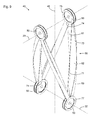
- FIG. 3 shows a schematic axonometric view of a segment 40 for forming a holding arm, as shown in FIG Figures 1 and 2 is shown.
- the segment 40 comprises four respective annular or substantially annular node components 50.
- Two node components 50 are each arranged rotationally symmetrical to a first pivot axis 22, two further node components 50 are arranged symmetrically to a second pivot axis 23.
- the node components 50 are in particular designed and arranged to accommodate two in FIG. 3 not shown, a shaft parallel to the first pivot axis 22 and a further shaft parallel to the second pivot axis 23.
- the segment 40 can be connected to adjacent segments or other parts of a support arm.
- the node components 50 are designed in particular as bearings or as parts of bearings, for example as bearing shells for plain or roller bearings, or for receiving bearing shells.
- the longitudinal axis 48 of the segment 40 is defined by the midpoints between the mutually opposite nodal components 50.
- the longitudinal axis 48 of the segment 40 is that straight line which intersects the pivot axes 22, 23 in each case in the middle between the respective node components.
- the pivot axes 22, 23 are each in particular orthogonal to the longitudinal axis 48 of the segment 40.
- the pivot axes 22, 23 are in particular orthogonal to each other.
- the node components 50 are connected by four equally long struts 60.
- Each strut 60 mechanically rigidly connects a node component 50 to the first pivot axis 22 and a node component 50 to the second pivot axis 23.
- Each node component 50 on the first pivot axis 22 is connected via a respective strut 60 with both node components 50 mechanically rigidly connected to the second pivot axis 23.
- Each node component 50 on the second pivot axis 23 is mechanically rigidly connected via a respective strut 60 to each node component 50 on the first pivot axis 22.
- Each strut 60 is straight or, as in FIG. 3 represented, at least partially helically formed.
- the segment 40 is designed in particular such that each strut 60 essentially only has to absorb tensile or compressive forces.
- Each strut 60 is composed of three plate-shaped components 61, 62, 63 composed. The plate-shaped members 61, 62, 63 are each curved or twisted.
- Each strut 60 includes a twisted plate-shaped inner member 61, a twisted plate-shaped connecting web 62, and a curved plate-shaped outer member 63. Since the inner member 61 and the connecting web 62 are twisted, they are starting from an original planar state each stretched at their longitudinal edges and / or compressed in middle regions between the longitudinal edges.
- the plate-shaped inner component 61, the plate-shaped connecting web 62 and the plate-shaped outer component 63 can each be plastically and / or elastically deformed (twisted, twisted or bent).
- the inner member 61, the connecting web 62 and the outer member 63 are arranged so that the cross section of the strut 60 is substantially I-shaped. In particular, in each case a first longitudinal edge 71 of the connecting web 62 with the inner component 61 and a second longitudinal edge 73 of the connecting web 62 with the outer component 63 are joined.
- FIG. 4 shows a further schematic axonometric view of parts of the segment 40 FIG. 3 ,
- the node components 50 and the outer components 63 but not the inner components 61 and the connecting webs 62 are shown.
- a circular cylinder jacket 86 is shown.
- the cylinder axis 88 of the circular cylinder jacket 86 ie the straight line to which the circular cylinder jacket 86 is both cylindrically symmetrical (translation invariant) and rotationally symmetrical coincides with the longitudinal axis 48 of the segment 40 or is identical to this.
- the outer components 63 are substantially helical strip-shaped cutouts of the circular cylinder jacket 86, which are widened at the ends joined to the node components 50.
- FIG. 5 shows a further schematic axonometric representation of parts of the segment of the Figures 3 and 4 ,
- FIG. 5 are similar to in FIG. 4 only the node components 50 and the exterior components 63 are shown.
- FIG. 5 the circular cylinder jacket not shown.
- There are grooves 56 in the node components 50 can be seen, for receiving the ends of the inner members 61 and the connecting webs 62 (see. FIG. 3 ), in the FIG. 5 are not shown, are provided.
- FIG. 6 shows a further schematic axonometric representation of parts of the segment of the FIGS. 3 to 5 .
- the representation in FIG. 6 is different from the one of FIG. 3 in that the inner components are not shown.
- the representation in FIG. 6 is different from the one of FIG. 5 in that in addition to all node components 50 and the outer components 63 and the connecting webs 62 of all struts 60 are shown.
- the first edges 71 of the connecting webs 62 are straight or substantially straight.
- the struts 60 each have a T-shaped cross-section.
- FIG. 7 shows a schematic axonometric view of another segment 40 for a holding arm.
- This in FIG. 7 Segment 40 shown differs from that of the FIGS. 3 to 6 shown segment in that it comprises not only four, but six node components 50 and not only four, but eight struts 60.
- segment 40 has the shape of two mirror images of each other and arranged on common node components 50 mechanically rigidly interconnected segments of the type, as they are based on FIGS. 3 to 6 is shown.
- Four terminal or arranged at the ends of the segment 40 and pivot axes 22, 23 defining node components 50 are mechanically rigidly connected to two struts 60, and about this with one of two central node components.
- Each of the middle, not one of the two pivot axes 22, 23 associated with node components 50 is mechanically rigidly connected via four struts with all four the pivot axes 22, 23 associated node components.
- FIGS. 3 to 7 Segments shown can be supplemented by a panel, which is not shown in the figures.
- the cladding has in particular the shape of a lateral surface of a circular cylinder.
- This lateral surface of a circular cylinder is particularly similar to that in FIG. 4 Circular cylinder jacket shown, however, has a slightly larger diameter, so that in particular the inside of the panel rests on the outside of the struts 60.
- Such a cladding can protect components and components located in the interior of the segment from environmental influences and damage. Especially in the case of the basis of FIG. 7
- the segment can also serve to receive forces and to stiffen the segment.
- the cladding can be a mechanical one create rigid connection between two lying on the same side of the longitudinal axis 48 terminal node components.
- FIG. 8 shows a schematic representation of components for one of the basis of the FIGS. 3 to 7 represented segments.
- a node component 50 is shown axonometrically.
- the planar components 61, 62, 63 namely the inner component 61, the connecting web 62 and the outer component 63, are shown in a simple plan view and in the plane shape present prior to the manufacture of a strut.
- the connecting web 62 has a straight or essentially straight first edge 71 for, in particular, a material connection to the inner component 61 and a curved second edge 73 for, in particular, integral connection with the outer component 63.
- the node component 50 is manufactured in particular by means of milling and / or another machining method or by means of a 3D printing method or by means of a sintering method.
- the node component 50 has grooves 56 for receiving the ends 75, 76, 77 of the flat components 61, 62, 63.
- the node component 50 bores 51. Through the holes 51 through the ends 75, 76, 77 of the flat components 61, 62, 63 are joined in the grooves 56, for example by laser welding.
- the ends 75, 76, 77 of the flat components 61, 62, 63 may have corresponding bores and be held in a form-fitting manner after insertion into the grooves 56 by means of pins 52 inserted into the bores 52.
- FIG. 9 shows a schematic axonometric view of another segment 40 for a holding arm, which in some features, properties and functions based on the FIGS. 3 to 8 The segments shown are similar or equivalent.
- FIG. 9 Segment 40 shown differs from the basis of the FIGS. 3 to 6 represented segment in particular by another connection between the inner components 61 and the outer components 63 on the one hand and the node components 50 on the other.
- the inner components 61 and the outer components 63 are each formed annularly at their ends 75, 77.
- the ends 75 of the inner components 61 lie against the inner sides of the node components 50 flat and are connected to these in particular cohesively.
- the inner side of a node component 50 is in each case the surface of the node component 50 facing the opposing node component.
- the ends 77 of the outer components 63 abut against the outer sides of the node components 50 and are in particular materially connected thereto.
- a node component 50 The outside of a node component 50 is in each case the surface of the node component 50 facing away from the opposite node component.
- a positive connection for example by means of screws or rivets, may be provided.
- the inner components 61 have bending edges 74 in the transition region to the annular ends 75, which abut flat against the respective node components 50.
- the transitions to the surface of each of the node components 50 abutting annular ends 77 are smooth.
- FIG. 10 time a schematic representation of components for the basis of FIG. 9 represented segment.
- a node component 50 is shown axonometrically.
- the planar components 61, 62, 63 namely the inner component 61, the connecting web 62 and the outer component 63, are shown in a simple plan view and in the plane shape present prior to the manufacture of a strut.
- the connecting web 62 has a straight or essentially straight first edge 71 for, in particular, a material connection to the inner component 61 and a curved second edge 73 for, in particular, integral connection with the outer component 63.
- the node member 50 has a simple shape with two parallel and planar surface portions and a peripheral portion of constant width therebetween.
- the node component 50 can be cut out of plate-shaped semifinished product due to its simple shape.
- the node component 50 bores 51.
- the ends 75, 76, 77 of the flat components 61, 62, 63 have corresponding bores 65.
- the ends 75, 76, 77 of the flat components 61, 62, 63 can be used, the ends 75, 76, 77 of the flat components 61, 62, Connect 63 with the node components 50.
- At each bending edge 74 may be provided a perforation or a linear weakening of the plate-shaped material in order to simplify the edges.
- FIG. 11 shows a schematic representation of planar components 62, 63 for an alternative embodiment of a strut.
- the planar components 62, 63 are designed to jointly form a T-shaped cross section of a bent, in particular a helically bent strut.
- a planar component 62 has rectangular pins 92 which are provided, arranged and designed to engage in corresponding recesses 93 in the other flat component 63.
- the flat components can be joined by force or friction fit and / or by material bond (welding, soldering, gluing, etc.).
- split pins or clamps can hold the flat components 62, 63 together.
- Deviating from the illustration based on the FIG. 11 can be provided a further sheet-like component, similar to the reference to the FIGS. 3 to 8 represented segments. Together with this further flat component, an I-shaped cross section of a strut can be generated.
- the sheet-like component 62 can with the in FIG. 11 not shown further flat component form-fitting manner (similar to the flat component 61) and / or material or force or frictionally connected.
- the outer surfaces of a segment may not have the shape of cutouts of a cylinder barrel but, for example, the shape of cutouts of a cone shell.
- each planar outer component 63 has the shape of a conical spiral or a conical helix or, more generally, the shape of a loxodrome.
- FIG. 12 shows a schematic axonometric representation of a possible positive connection of two flat components 62, 63, in particular a connecting web 62 and an outer member 63.
- both flat components 62, 63 are in FIG. 12 only sections shown to illustrate the positive connection.
- the entire planar component 62, 63 may each have - apart from the features described below, in particular at the edges - a shape, in particular an outline, as it is based on the FIGS. 8 . 10 or 11 is shown.
- the flat components 62, 63 have circular openings, which may be provided to reduce the mass and / or as attachment points.
- the connecting web 62 has a nose or a tab or a pin 92 with a recess 94.
- the pin 92 is inserted through a slot-shaped recess 93 in the outer member 63.
- a resilient latch 95 is inserted into the recess 94 in the pin 92.
- the resilient latch 95 is located on the side facing away from the connecting web 62 outside of the outer component 63 and thus positively prevents withdrawal of the pin 92 on the connecting web 62 from the recess 92 in the outer member 63rd
- FIG. 13 shows a further schematic axonometric representation of the connecting web 62, the outer member 63 and the resilient bolt 95 from FIG. 12 ,
- the connecting web 62, the outer member 63 and the resilient latch 95 are shown spaced from each other. Arrows indicate how initially the pin 92 can be inserted into the slot-shaped recess 93 on the outer component 63 and then the resilient latch 95 can be inserted into the recess 94 in the pin 92.
- the resilient latch 95 has substantially the shape of a flat ring. Grooves on the resilient latch 95 are provided to receive edges of the recess 94 in the pin and so the bolt 95 positively in the in FIG. 12 hold position shown.
- FIG. 14 shows a schematic axonometric representation of another possible positive connection of two flat components 62, 63, in particular a connecting web 62 and an outer member 63.
- the connecting web 62 and the outer member 63 are connected by a rivet 96 with each other form-fitting manner.
- FIG. 15 shows a further schematic axonometric representation of the connecting web 62, the outer member 63 and the rivet 96 from FIG. 14 .
- the type of representation corresponds to that of the FIG. 13 with the rivet 96 in FIG. 15 shown in dashed line in its pre-insertion and deformation and in solid lines in its already deformed shape.
- the connecting web 62 has a bay-shaped recess 91 with two lugs 99.
- An arrow indicates how a ring 97 with grooves 98 is first inserted into the bay-shaped recess 91 on the connecting web 62.
- Each groove 98 on the ring 97 receives a nose 99 on the bay-shaped recess.
- the rivet 96 is inserted into the recess 93 in the outer member 63 and the ring 97 and deformed to positively connect the ring 97 and thus also the connecting web 62 with the outer member 63.
- the deformation of the rivet may deviate from the illustration in FIG. 15 done at its opposite end.
- FIG. 16 shows a schematic axonometric representation of another possible positive connection of two flat components 62, 63, in particular a connecting web 62 and an outer member 63.
- the connecting web 62 and the outer member 63 are connected to each other by means of a screw 81 and a nut.
- FIG. 17 shows a further schematic axonometric representation of the connecting web 62, the outer member and the screw 81ausaus FIG. 14 and the screw 81 corresponding to the screw nut 82.
- the type of representation corresponds to that of FIG. 13 and 15 ,
- the connecting web 62 has a bay-shaped recess 91 with two lugs 99.
- An arrow indicates how first a nut 82 with grooves 83 is inserted into the bay-shaped recess 91 on the connecting web 62.
- Each groove 83 on the nut 82 receives a nose 99 on the bay-shaped recess.
- By a further arrow is indicated how then the screw 81 is inserted through the recess 93 in the outer member 63 inserted into the nut 82 with this, in order to connect the nut 82 and thus the connecting web 62 form-fitting manner with the outer member 63.
- FIG. 18 shows a schematic axonometric representation of another possible positive connection of two flat components 62, 63, in particular a connecting web 62 and an outer member 63.
- the connecting web 62 and the outer member 63 are connected to each other by means of two locking lugs 84.
- FIG. 19 shows a further schematic axonometric representation of the connecting web 62 and the outer member 63 from FIG. 14 ,
- the type of representation corresponds to that of the Figures 13 . 15 and 17 ,
- the connecting web 62 has a bay-shaped recess 91 with two lugs 99.
- An arrow indicates how the latching hooks 84 are passed through the slot-shaped recess 93 in the outer component 63.
- the latching hooks 84 are elastically deformed by the edges of the slot-shaped recess 93 in the short term before the latching hook 84, the in FIG. 18 occupy shown positions in which they connect the connecting web 62 positively to the outer member 63.
- FIG. 20 shows a schematic representation of alternative cross sections of a strut.
- a T-shaped cross section of a strut with a web 62 and an outer member 63 is shown. This cross-section corresponds to the basis of FIG. 6 illustrated configuration.
- FIG. 20 Far right in FIG. 20 is a rectangular, namely trapezoidal, cross-section of a strut with an inner member 61, two connecting webs 62, 64 and an outer member 63 shown.
- FIG. 21 shows a schematic flow diagram of a method for producing a segment for a holding arm for positioning a medical instrument or a medical device.
- the method is also suitable for the production of a segment, which from the representations on the basis of FIGS. 3 to 9 have different features, properties and functions, reference numerals will be described below by way of example FIGS. 3 to 9 used to facilitate understanding.
- planar components 61, 62, 63, 64 are cut out of one or more different sheets or other plate-shaped semi-finished products, for example by laser cutting, water jet cutting, milling, sawing, etc.
- a second step 102 at least one of the sheet-like components 61, 62, 63, 64 is arched or bent.
- an inner component 61 and one or more connecting webs 62, 64 are twisted so that they each have a negative Gaussian curvature, and an outer component is bent so that it further has a vanishing Gaussian curvature, in particular the shape of a strip-shaped section of a circular cylinder jacket.
- the buckling and / or bending of the sheet-like components can be done manually and / or by machine.
- a third step 103 the flat components 61, 62, 63, 64 are joined to form a strut 60.
- the sheet-like components 61, 62, 63, 64 are joined to one another in particular by means of laser or other welding, soldering, gluing or in another way material, force or friction fit and / or positive fit.
- a fourth step 104 the ends of the strut 60 formed by means of the first step 101, the second step 102 and the third step 103 are joined, each with a node component 50.
- a fifth step 105 the node components 50 are joined with further struts 60 and these with further node components 50.
Landscapes
- Engineering & Computer Science (AREA)
- Robotics (AREA)
- Health & Medical Sciences (AREA)
- Mechanical Engineering (AREA)
- Surgery (AREA)
- Life Sciences & Earth Sciences (AREA)
- Animal Behavior & Ethology (AREA)
- Veterinary Medicine (AREA)
- Medical Informatics (AREA)
- Molecular Biology (AREA)
- Biomedical Technology (AREA)
- General Health & Medical Sciences (AREA)
- Public Health (AREA)
- Heart & Thoracic Surgery (AREA)
- Nuclear Medicine, Radiotherapy & Molecular Imaging (AREA)
- Oral & Maxillofacial Surgery (AREA)
- Pathology (AREA)
- Endoscopes (AREA)
- Mutual Connection Of Rods And Tubes (AREA)
- Apparatus For Radiation Diagnosis (AREA)
Applications Claiming Priority (1)
| Application Number | Priority Date | Filing Date | Title |
|---|---|---|---|
| DE102014104557.2A DE102014104557A1 (de) | 2014-04-01 | 2014-04-01 | Haltearm zum Positionieren eines medizinischen Instruments oder eines medizinischen Geräts |
Publications (3)
| Publication Number | Publication Date |
|---|---|
| EP2926759A2 true EP2926759A2 (fr) | 2015-10-07 |
| EP2926759A3 EP2926759A3 (fr) | 2015-10-28 |
| EP2926759B1 EP2926759B1 (fr) | 2022-10-26 |
Family
ID=52813962
Family Applications (1)
| Application Number | Title | Priority Date | Filing Date |
|---|---|---|---|
| EP15162185.1A Active EP2926759B1 (fr) | 2014-04-01 | 2015-04-01 | Bras de support destiné à positionner un instrument médical ou un appareil médical |
Country Status (3)
| Country | Link |
|---|---|
| US (2) | US10328584B2 (fr) |
| EP (1) | EP2926759B1 (fr) |
| DE (1) | DE102014104557A1 (fr) |
Families Citing this family (5)
| Publication number | Priority date | Publication date | Assignee | Title |
|---|---|---|---|---|
| EP3189946A1 (fr) | 2016-01-08 | 2017-07-12 | ABB Schweiz AG | Robot industriel pourvu d'un bras inférieur modulaire |
| US11033342B2 (en) * | 2018-02-19 | 2021-06-15 | Gregory P. Schmitz | Universal joint for surgical robotics |
| US11458641B2 (en) | 2018-05-23 | 2022-10-04 | General Electric Company | Robotic arm assembly construction |
| EP4070927A1 (fr) * | 2021-04-08 | 2022-10-12 | Stacmol Ricerca E Sviluppo S.r.l. | Tête de coupe |
| RU208913U1 (ru) * | 2021-09-23 | 2022-01-21 | Федеральное государственное бюджетное учреждение науки Институт машиноведения им. А.А. Благонравова Российской академии наук (ИМАШ РАН) | Хирургический робот-манипулятор |
Family Cites Families (15)
| Publication number | Priority date | Publication date | Assignee | Title |
|---|---|---|---|---|
| FR2368430A1 (fr) * | 1976-10-22 | 1978-05-19 | Pingon Manubat Sa | Fleche repliable pour grues telescopiques |
| US4411402A (en) * | 1980-11-03 | 1983-10-25 | Keller Max P | Adjustable indicator holders |
| US5052375A (en) * | 1990-02-21 | 1991-10-01 | John G. Stark | Instrumented orthopedic restraining device and method of use |
| US5214749A (en) * | 1991-06-12 | 1993-05-25 | Massachusetts Institute Of Technology | Dynamic control of a robot with its center of mass decoupled from an end effector by a redundant linkage |
| US5584398A (en) * | 1995-12-11 | 1996-12-17 | Lin; Jack | CD storage rack and lamp assembly |
| US6446924B1 (en) * | 2000-08-22 | 2002-09-10 | Troy Daniel Olson | Apparatus and method for supporting a dial test indicator |
| JP2005144627A (ja) * | 2003-11-18 | 2005-06-09 | Ntn Corp | リンク作動装置 |
| US8167872B2 (en) * | 2006-01-25 | 2012-05-01 | Intuitive Surgical Operations, Inc. | Center robotic arm with five-bar spherical linkage for endoscopic camera |
| US8469945B2 (en) * | 2006-01-25 | 2013-06-25 | Intuitive Surgical Operations, Inc. | Center robotic arm with five-bar spherical linkage for endoscopic camera |
| US7862524B2 (en) * | 2006-03-23 | 2011-01-04 | Carignan Craig R | Portable arm exoskeleton for shoulder rehabilitation |
| CN101823263B (zh) * | 2009-03-07 | 2013-02-13 | 鸿富锦精密工业(深圳)有限公司 | 机器人的臂部件及其制造方法以及具有该臂部件的机器人 |
| DE102011119813B4 (de) * | 2011-12-01 | 2015-09-03 | Leica Microsystems (Schweiz) Ag | Stativ für ein Operationsmikroskop |
| KR101917076B1 (ko) * | 2012-02-21 | 2018-11-09 | 삼성전자주식회사 | 링크 유닛 및 이를 가지는 암 모듈 |
| DE102012018533B4 (de) * | 2012-09-19 | 2022-12-01 | Fraunhofer-Gesellschaft zur Förderung der angewandten Forschung e.V. | Manipulator für die minimalinvasive Chirurgie |
| CN202902005U (zh) * | 2012-11-01 | 2013-04-24 | 陈清辉 | 具有抽屉的立灯 |
-
2014
- 2014-04-01 DE DE102014104557.2A patent/DE102014104557A1/de active Pending
-
2015
- 2015-04-01 EP EP15162185.1A patent/EP2926759B1/fr active Active
- 2015-04-01 US US14/676,405 patent/US10328584B2/en active Active
-
2019
- 2019-05-07 US US16/405,217 patent/US11338454B2/en active Active
Non-Patent Citations (1)
| Title |
|---|
| None |
Also Published As
| Publication number | Publication date |
|---|---|
| US10328584B2 (en) | 2019-06-25 |
| EP2926759B1 (fr) | 2022-10-26 |
| US11338454B2 (en) | 2022-05-24 |
| US20190255715A1 (en) | 2019-08-22 |
| EP2926759A3 (fr) | 2015-10-28 |
| DE102014104557A1 (de) | 2015-10-01 |
| US20150283710A1 (en) | 2015-10-08 |
Similar Documents
| Publication | Publication Date | Title |
|---|---|---|
| EP2926759B1 (fr) | Bras de support destiné à positionner un instrument médical ou un appareil médical | |
| DE4305667A1 (en) | Ball joint element with two-end body and longitudinal axis - has body with higher resistance to radially inwards deformation at one end | |
| EP3096963B1 (fr) | Attache de composant avec surface de support supportant les forces transversales | |
| DE102016205975A1 (de) | Aussenzahnrad, exzentrische Oszillationsgetriebevorrichtung, Roboter, Verfahren für die Verwendung einer exzentrischen Oszillationsgetriebevorrichtung und Satz von Getriebevorrichtungen | |
| DE60125095T2 (de) | Teilbares, modulares und orientierbares Element für selbstausrichtende Kabelkanäle | |
| DE102012108031A1 (de) | Halter für eine Fügevorrichtung | |
| DE112018001013B4 (de) | Montageaufbau für ein lagerglied und untersetzungsvorrichtung | |
| DE602004002940T2 (de) | Kardangelenk mit haltemechanismus | |
| EP3234389B1 (fr) | Élément d'accouplement et dispositif d'accouplement pour la transmission axiale de couple et ensemble de lamelles pour de tels éléments d'accouplement | |
| DE102019130855A1 (de) | Verbindungssystem und Regalsystem | |
| EP1953441A2 (fr) | Conduite dotée d'une pièce de raccordement | |
| DE102016207796A1 (de) | Einspannvorrichtung zum Einspannen eines Zangenarms einer Fügezange | |
| DE102008006489A1 (de) | Spannelement | |
| DE202016008902U1 (de) | Befestigungsvorrichtung zum Befestigen eines röhrenförmigen Objekts | |
| EP1431604A1 (fr) | Joint universel avec élément de retenue. | |
| DE102015009376B4 (de) | Bauteil eines Kraftfahrzeugs und Verfahren zur Montage eines Bauteils | |
| DE202018107067U1 (de) | Schnellverschluss | |
| EP3054810B1 (fr) | Système de noeuds d'assemblage et kit d'assemblage | |
| DE69912439T2 (de) | Grö enverstellbare Halteringvorrichtung | |
| EP3305475A1 (fr) | Unité d'articulation | |
| DE102016221044A1 (de) | Kippsegmentlager | |
| DE102016102643B3 (de) | Stabförmige Baugruppe mit Umkrempelung sowie Verfahren zur Herstellung der stabförmigen Baugruppe und Verwendung eines Mantels aus Gewebelage zum Bilden der Umkrempelung | |
| DE202005008121U1 (de) | Rohrförmiges Element mit Anschlag | |
| CH702410B1 (de) | Verbindungsvorrichtung für ein Rohrsystem, sowie Möbelstück mit einem solchen Rohrsystem. | |
| DE102004054359B4 (de) | Vorrichtung zur Erzeugung einer Torsionsbewegung und Verwendung derselben |
Legal Events
| Date | Code | Title | Description |
|---|---|---|---|
| PUAL | Search report despatched |
Free format text: ORIGINAL CODE: 0009013 |
|
| PUAI | Public reference made under article 153(3) epc to a published international application that has entered the european phase |
Free format text: ORIGINAL CODE: 0009012 |
|
| AK | Designated contracting states |
Kind code of ref document: A2 Designated state(s): AL AT BE BG CH CY CZ DE DK EE ES FI FR GB GR HR HU IE IS IT LI LT LU LV MC MK MT NL NO PL PT RO RS SE SI SK SM TR |
|
| AX | Request for extension of the european patent |
Extension state: BA ME |
|
| RAP1 | Party data changed (applicant data changed or rights of an application transferred) |
Owner name: KARL STORZ GMBH & CO. KG |
|
| AK | Designated contracting states |
Kind code of ref document: A3 Designated state(s): AL AT BE BG CH CY CZ DE DK EE ES FI FR GB GR HR HU IE IS IT LI LT LU LV MC MK MT NL NO PL PT RO RS SE SI SK SM TR |
|
| AX | Request for extension of the european patent |
Extension state: BA ME |
|
| RIC1 | Information provided on ipc code assigned before grant |
Ipc: B25J 9/00 20060101ALI20150924BHEP Ipc: B25J 18/00 20060101ALI20150924BHEP Ipc: A61B 19/00 20060101AFI20150924BHEP Ipc: B25J 17/02 20060101ALI20150924BHEP |
|
| 17P | Request for examination filed |
Effective date: 20160413 |
|
| RBV | Designated contracting states (corrected) |
Designated state(s): AL AT BE BG CH CY CZ DE DK EE ES FI FR GB GR HR HU IE IS IT LI LT LU LV MC MK MT NL NO PL PT RO RS SE SI SK SM TR |
|
| STAA | Information on the status of an ep patent application or granted ep patent |
Free format text: STATUS: EXAMINATION IS IN PROGRESS |
|
| 17Q | First examination report despatched |
Effective date: 20170607 |
|
| RAP1 | Party data changed (applicant data changed or rights of an application transferred) |
Owner name: KARL STORZ SE & CO. KG |
|
| STAA | Information on the status of an ep patent application or granted ep patent |
Free format text: STATUS: EXAMINATION IS IN PROGRESS |
|
| REG | Reference to a national code |
Ref country code: DE Ref legal event code: R079 Ref document number: 502015016126 Country of ref document: DE Free format text: PREVIOUS MAIN CLASS: A61B0019000000 Ipc: A61B0090500000 |
|
| RIC1 | Information provided on ipc code assigned before grant |
Ipc: B25J 18/00 20060101ALI20220325BHEP Ipc: B25J 17/02 20060101ALI20220325BHEP Ipc: B25J 9/00 20060101ALI20220325BHEP Ipc: A61B 34/30 20160101ALI20220325BHEP Ipc: A61B 90/50 20160101AFI20220325BHEP |
|
| GRAP | Despatch of communication of intention to grant a patent |
Free format text: ORIGINAL CODE: EPIDOSNIGR1 |
|
| STAA | Information on the status of an ep patent application or granted ep patent |
Free format text: STATUS: GRANT OF PATENT IS INTENDED |
|
| INTG | Intention to grant announced |
Effective date: 20220510 |
|
| GRAS | Grant fee paid |
Free format text: ORIGINAL CODE: EPIDOSNIGR3 |
|
| GRAA | (expected) grant |
Free format text: ORIGINAL CODE: 0009210 |
|
| STAA | Information on the status of an ep patent application or granted ep patent |
Free format text: STATUS: THE PATENT HAS BEEN GRANTED |
|
| AK | Designated contracting states |
Kind code of ref document: B1 Designated state(s): AL AT BE BG CH CY CZ DE DK EE ES FI FR GB GR HR HU IE IS IT LI LT LU LV MC MK MT NL NO PL PT RO RS SE SI SK SM TR |
|
| REG | Reference to a national code |
Ref country code: GB Ref legal event code: FG4D Free format text: NOT ENGLISH |
|
| REG | Reference to a national code |
Ref country code: CH Ref legal event code: EP |
|
| REG | Reference to a national code |
Ref country code: DE Ref legal event code: R096 Ref document number: 502015016126 Country of ref document: DE |
|
| REG | Reference to a national code |
Ref country code: AT Ref legal event code: REF Ref document number: 1526498 Country of ref document: AT Kind code of ref document: T Effective date: 20221115 |
|
| REG | Reference to a national code |
Ref country code: IE Ref legal event code: FG4D Free format text: LANGUAGE OF EP DOCUMENT: GERMAN |
|
| REG | Reference to a national code |
Ref country code: LT Ref legal event code: MG9D |
|
| REG | Reference to a national code |
Ref country code: NL Ref legal event code: MP Effective date: 20221026 |
|
| PG25 | Lapsed in a contracting state [announced via postgrant information from national office to epo] |
Ref country code: NL Free format text: LAPSE BECAUSE OF FAILURE TO SUBMIT A TRANSLATION OF THE DESCRIPTION OR TO PAY THE FEE WITHIN THE PRESCRIBED TIME-LIMIT Effective date: 20221026 |
|
| PG25 | Lapsed in a contracting state [announced via postgrant information from national office to epo] |
Ref country code: SE Free format text: LAPSE BECAUSE OF FAILURE TO SUBMIT A TRANSLATION OF THE DESCRIPTION OR TO PAY THE FEE WITHIN THE PRESCRIBED TIME-LIMIT Effective date: 20221026 Ref country code: PT Free format text: LAPSE BECAUSE OF FAILURE TO SUBMIT A TRANSLATION OF THE DESCRIPTION OR TO PAY THE FEE WITHIN THE PRESCRIBED TIME-LIMIT Effective date: 20230227 Ref country code: NO Free format text: LAPSE BECAUSE OF FAILURE TO SUBMIT A TRANSLATION OF THE DESCRIPTION OR TO PAY THE FEE WITHIN THE PRESCRIBED TIME-LIMIT Effective date: 20230126 Ref country code: LT Free format text: LAPSE BECAUSE OF FAILURE TO SUBMIT A TRANSLATION OF THE DESCRIPTION OR TO PAY THE FEE WITHIN THE PRESCRIBED TIME-LIMIT Effective date: 20221026 Ref country code: FI Free format text: LAPSE BECAUSE OF FAILURE TO SUBMIT A TRANSLATION OF THE DESCRIPTION OR TO PAY THE FEE WITHIN THE PRESCRIBED TIME-LIMIT Effective date: 20221026 Ref country code: ES Free format text: LAPSE BECAUSE OF FAILURE TO SUBMIT A TRANSLATION OF THE DESCRIPTION OR TO PAY THE FEE WITHIN THE PRESCRIBED TIME-LIMIT Effective date: 20221026 |
|
| PG25 | Lapsed in a contracting state [announced via postgrant information from national office to epo] |
Ref country code: RS Free format text: LAPSE BECAUSE OF FAILURE TO SUBMIT A TRANSLATION OF THE DESCRIPTION OR TO PAY THE FEE WITHIN THE PRESCRIBED TIME-LIMIT Effective date: 20221026 Ref country code: PL Free format text: LAPSE BECAUSE OF FAILURE TO SUBMIT A TRANSLATION OF THE DESCRIPTION OR TO PAY THE FEE WITHIN THE PRESCRIBED TIME-LIMIT Effective date: 20221026 Ref country code: LV Free format text: LAPSE BECAUSE OF FAILURE TO SUBMIT A TRANSLATION OF THE DESCRIPTION OR TO PAY THE FEE WITHIN THE PRESCRIBED TIME-LIMIT Effective date: 20221026 Ref country code: IS Free format text: LAPSE BECAUSE OF FAILURE TO SUBMIT A TRANSLATION OF THE DESCRIPTION OR TO PAY THE FEE WITHIN THE PRESCRIBED TIME-LIMIT Effective date: 20230226 Ref country code: HR Free format text: LAPSE BECAUSE OF FAILURE TO SUBMIT A TRANSLATION OF THE DESCRIPTION OR TO PAY THE FEE WITHIN THE PRESCRIBED TIME-LIMIT Effective date: 20221026 Ref country code: GR Free format text: LAPSE BECAUSE OF FAILURE TO SUBMIT A TRANSLATION OF THE DESCRIPTION OR TO PAY THE FEE WITHIN THE PRESCRIBED TIME-LIMIT Effective date: 20230127 |
|
| P01 | Opt-out of the competence of the unified patent court (upc) registered |
Effective date: 20230527 |
|
| REG | Reference to a national code |
Ref country code: DE Ref legal event code: R097 Ref document number: 502015016126 Country of ref document: DE |
|
| PG25 | Lapsed in a contracting state [announced via postgrant information from national office to epo] |
Ref country code: SM Free format text: LAPSE BECAUSE OF FAILURE TO SUBMIT A TRANSLATION OF THE DESCRIPTION OR TO PAY THE FEE WITHIN THE PRESCRIBED TIME-LIMIT Effective date: 20221026 Ref country code: RO Free format text: LAPSE BECAUSE OF FAILURE TO SUBMIT A TRANSLATION OF THE DESCRIPTION OR TO PAY THE FEE WITHIN THE PRESCRIBED TIME-LIMIT Effective date: 20221026 Ref country code: EE Free format text: LAPSE BECAUSE OF FAILURE TO SUBMIT A TRANSLATION OF THE DESCRIPTION OR TO PAY THE FEE WITHIN THE PRESCRIBED TIME-LIMIT Effective date: 20221026 Ref country code: DK Free format text: LAPSE BECAUSE OF FAILURE TO SUBMIT A TRANSLATION OF THE DESCRIPTION OR TO PAY THE FEE WITHIN THE PRESCRIBED TIME-LIMIT Effective date: 20221026 Ref country code: CZ Free format text: LAPSE BECAUSE OF FAILURE TO SUBMIT A TRANSLATION OF THE DESCRIPTION OR TO PAY THE FEE WITHIN THE PRESCRIBED TIME-LIMIT Effective date: 20221026 |
|
| PG25 | Lapsed in a contracting state [announced via postgrant information from national office to epo] |
Ref country code: SK Free format text: LAPSE BECAUSE OF FAILURE TO SUBMIT A TRANSLATION OF THE DESCRIPTION OR TO PAY THE FEE WITHIN THE PRESCRIBED TIME-LIMIT Effective date: 20221026 Ref country code: AL Free format text: LAPSE BECAUSE OF FAILURE TO SUBMIT A TRANSLATION OF THE DESCRIPTION OR TO PAY THE FEE WITHIN THE PRESCRIBED TIME-LIMIT Effective date: 20221026 |
|
| PLBE | No opposition filed within time limit |
Free format text: ORIGINAL CODE: 0009261 |
|
| STAA | Information on the status of an ep patent application or granted ep patent |
Free format text: STATUS: NO OPPOSITION FILED WITHIN TIME LIMIT |
|
| 26N | No opposition filed |
Effective date: 20230727 |
|
| PG25 | Lapsed in a contracting state [announced via postgrant information from national office to epo] |
Ref country code: SI Free format text: LAPSE BECAUSE OF FAILURE TO SUBMIT A TRANSLATION OF THE DESCRIPTION OR TO PAY THE FEE WITHIN THE PRESCRIBED TIME-LIMIT Effective date: 20221026 |
|
| REG | Reference to a national code |
Ref country code: CH Ref legal event code: PL |
|
| PG25 | Lapsed in a contracting state [announced via postgrant information from national office to epo] |
Ref country code: LU Free format text: LAPSE BECAUSE OF NON-PAYMENT OF DUE FEES Effective date: 20230401 |
|
| REG | Reference to a national code |
Ref country code: BE Ref legal event code: MM Effective date: 20230430 |
|
| PG25 | Lapsed in a contracting state [announced via postgrant information from national office to epo] |
Ref country code: MC Free format text: LAPSE BECAUSE OF FAILURE TO SUBMIT A TRANSLATION OF THE DESCRIPTION OR TO PAY THE FEE WITHIN THE PRESCRIBED TIME-LIMIT Effective date: 20221026 |
|
| PG25 | Lapsed in a contracting state [announced via postgrant information from national office to epo] |
Ref country code: MC Free format text: LAPSE BECAUSE OF FAILURE TO SUBMIT A TRANSLATION OF THE DESCRIPTION OR TO PAY THE FEE WITHIN THE PRESCRIBED TIME-LIMIT Effective date: 20221026 Ref country code: LI Free format text: LAPSE BECAUSE OF NON-PAYMENT OF DUE FEES Effective date: 20230430 Ref country code: CH Free format text: LAPSE BECAUSE OF NON-PAYMENT OF DUE FEES Effective date: 20230430 |
|
| REG | Reference to a national code |
Ref country code: IE Ref legal event code: MM4A |
|
| PG25 | Lapsed in a contracting state [announced via postgrant information from national office to epo] |
Ref country code: BE Free format text: LAPSE BECAUSE OF NON-PAYMENT OF DUE FEES Effective date: 20230430 |
|
| PG25 | Lapsed in a contracting state [announced via postgrant information from national office to epo] |
Ref country code: IE Free format text: LAPSE BECAUSE OF NON-PAYMENT OF DUE FEES Effective date: 20230401 |
|
| PG25 | Lapsed in a contracting state [announced via postgrant information from national office to epo] |
Ref country code: IE Free format text: LAPSE BECAUSE OF NON-PAYMENT OF DUE FEES Effective date: 20230401 |
|
| REG | Reference to a national code |
Ref country code: AT Ref legal event code: MM01 Ref document number: 1526498 Country of ref document: AT Kind code of ref document: T Effective date: 20230401 |
|
| PGFP | Annual fee paid to national office [announced via postgrant information from national office to epo] |
Ref country code: GB Payment date: 20240423 Year of fee payment: 10 |
|
| PGFP | Annual fee paid to national office [announced via postgrant information from national office to epo] |
Ref country code: DE Payment date: 20240429 Year of fee payment: 10 |
|
| PG25 | Lapsed in a contracting state [announced via postgrant information from national office to epo] |
Ref country code: AT Free format text: LAPSE BECAUSE OF NON-PAYMENT OF DUE FEES Effective date: 20230401 |
|
| PG25 | Lapsed in a contracting state [announced via postgrant information from national office to epo] |
Ref country code: AT Free format text: LAPSE BECAUSE OF NON-PAYMENT OF DUE FEES Effective date: 20230401 |
|
| PGFP | Annual fee paid to national office [announced via postgrant information from national office to epo] |
Ref country code: IT Payment date: 20240423 Year of fee payment: 10 Ref country code: FR Payment date: 20240430 Year of fee payment: 10 |