EP2926558B1 - Procédé et système de calcul de profondeur de champ étendue pour des images microscopiques - Google Patents
Procédé et système de calcul de profondeur de champ étendue pour des images microscopiques Download PDFInfo
- Publication number
- EP2926558B1 EP2926558B1 EP13858441.2A EP13858441A EP2926558B1 EP 2926558 B1 EP2926558 B1 EP 2926558B1 EP 13858441 A EP13858441 A EP 13858441A EP 2926558 B1 EP2926558 B1 EP 2926558B1
- Authority
- EP
- European Patent Office
- Prior art keywords
- image
- images
- stack
- energy
- aligned
- Prior art date
- Legal status (The legal status is an assumption and is not a legal conclusion. Google has not performed a legal analysis and makes no representation as to the accuracy of the status listed.)
- Active
Links
Images


Classifications
-
- G—PHYSICS
- G06—COMPUTING OR CALCULATING; COUNTING
- G06T—IMAGE DATA PROCESSING OR GENERATION, IN GENERAL
- G06T5/00—Image enhancement or restoration
- G06T5/50—Image enhancement or restoration using two or more images, e.g. averaging or subtraction
-
- G—PHYSICS
- G06—COMPUTING OR CALCULATING; COUNTING
- G06T—IMAGE DATA PROCESSING OR GENERATION, IN GENERAL
- G06T5/00—Image enhancement or restoration
- G06T5/73—Deblurring; Sharpening
-
- G—PHYSICS
- G06—COMPUTING OR CALCULATING; COUNTING
- G06T—IMAGE DATA PROCESSING OR GENERATION, IN GENERAL
- G06T2207/00—Indexing scheme for image analysis or image enhancement
- G06T2207/10—Image acquisition modality
- G06T2207/10024—Color image
-
- G—PHYSICS
- G06—COMPUTING OR CALCULATING; COUNTING
- G06T—IMAGE DATA PROCESSING OR GENERATION, IN GENERAL
- G06T2207/00—Indexing scheme for image analysis or image enhancement
- G06T2207/10—Image acquisition modality
- G06T2207/10056—Microscopic image
-
- G—PHYSICS
- G06—COMPUTING OR CALCULATING; COUNTING
- G06T—IMAGE DATA PROCESSING OR GENERATION, IN GENERAL
- G06T2207/00—Indexing scheme for image analysis or image enhancement
- G06T2207/20—Special algorithmic details
- G06T2207/20212—Image combination
- G06T2207/20221—Image fusion; Image merging
Definitions
- the invention relates to image processing field in general and particularly to a method and system for extending depth of field in an imaging device.
- Limited depth of field is a common problem in imaging devices such as conventional light microscope. Objects imaged in such cases are sharply in focus over a limited distance known as the depth of field.
- the Depth of field (DOF) is the distance between the nearest and farthest objects in a scene that appear acceptably sharp in an image. Typically sharpness decreases with depth resulting in blurriness in at least some part of the image.
- DOE Depth of field
- high numerical aperture results in a very shallow depth of field, due to which it is not possible to have all region of the scene to be in focus.
- one or more digital image processing techniques may be employed. Using the digital image processing techniques, images taken at different depths of field of the same scene may be combined to produce a single composite image.
- the digital image processing techniques involve capturing multiple images of the same scene to form an image stack, identifying focused part from multiple images in the stack and recreating a single image with better depth of field by combining the focused parts.
- index information of the images in the stack is collected and processed to generate a depth map and composite image or/and a 3D model of the scene.
- the DOF in the composite image is the DOF in the composite image.
- the complexity, time required for processing the images, errors in the composite image and memory requirement also increases.
- the known solutions have one or the other drawback such as misalignment of the images in the stack, illumination variations in the composite image, noises in the Depth map and composite image, low quality of the composite image with blotchy background, edge shadowing and depth cross over, time complexity of the processes involved in depth of field calculations, too many manually configurable parameters and unable to manage large image stacks.
- an image processing method for constructing a composite image with extended depth of field from a plurality of source images as outlined in claim 1 is disclosed.
- a system for constructing a composite image with extended depth of field from a plurality of source images of a scene as outlined in claim 12 is disclosed.
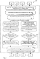
- FIG. 1 illustrates a flow chart of a method 100 for processing a plurality of images taken of a scene to generate a composite image with extended depth of field, according to an exemplary embodiment of the invention.
- the extended depth of field indicates a greater depth of field in the composite/processed image as compared to the original image before processing.
- the method obtains a plurality of image captured from a defined subject, where the images are taken from different positions for said subject.
- the images may be captured from any known imaging device such as but not limiting to, optical microscope, digital camera, etc.
- the images may be obtained from an archive having images of said subject captured from different positions.
- the different positions include capturing images from different 'Z' level of the imaging device. The obtained images are arranged in a stack to form an image stack.
- the method performs image alignment.
- the image alignment is the process of transforming different sets of image data in the image stack so that all the images may have one coordinate system.
- the image data may be obtained from different sensors, at different time, or from different viewpoints.
- the image alignment process enables processing of the images obtained from the different measurements/sources.
- the image alignment process involves finding an optimal one-to-one mapping between the pixels in one image to those in other images in the stack.
- a bi-directional image alignment method may be used for aligning the images in the image stack.
- the bi-directional image aligning method may include arranging the images in a sequence, such that the images are arranged as per their respective distance from the 'Z' level.
- a first reference image may be selected, such that the first reference image is the substantially central image in the image sequence.
- the alignment process further includes comparing the first reference image with immediate left side and immediate right side images in the sequence.
- the geometric transformation between the immediate left side image and the immediate right side image may be calculated with respect to the first reference image. Based on calculations, the immediate left side image and the immediate right side image may be aligned with the first reference image.
- immediate left side image may be compared with second image on the left side of the first reference image in the image sequence and immediate right side image may be compared with the second image on the right side of the first reference image in the image sequence and aligned with the immediate left side and the immediate right side images respectively.
- the process may be repeated for all the images thereby resulting in an aligned image stack that has substantially all images aligned with each other.
- the first and last image in the stack may have large variations and processing images in one direction that is from first to last may not provide effectively aligned image stack. Moreover processing images in one direction may result in a lot of time and memory consumption. On the other hand disclosed two way processing of images reduces time and result in better aligned stack of images.
- the process of comparison and alignment may be performed by any known conventional method in the image alignment process.
- the process of comparison and alignment may be performed by the parametric image alignment process.
- the parametric image alignment process includes specifying the particular geometric parametric transformation and then estimating the parameter by means of any known optimization method.
- the disclosed method uses a hierarchical coarse-to-fine approach of parametric image alignment using gradient descent optimization method and normalized cross correlation as cost function based on image pyramids.
- the exemplary illustrated method of comparison and alignment includes reducing the resolution on the images in the image stack by a scale factor in a range of between 1/2 to 1/16.
- the resolution of the images may be reduced by a scale factor of 1/8 of the original resolution to generate a stack of down sampled images.
- the method further includes creating an image pyramid of down sampled images and performing a coarse estimation of the transformation on the down sampled images.
- microscopic imaging the whole series of images or some part of a series of images may undergo through same transformations. Hence, if the second image undergoes through substantially same transformation, the transformation parameters obtained from the first image may be used as a clue or initial guess of transformation of next image.
- the hierarchical coarse-to-fine parametric image alignment process is implemented by a guided optimization process.
- the guided optimization process includes implementing an initial guess method/algorithm to search for global optima of the cost function faster by making it to start the iterations near the global optima position of the previous image cost function.
- the illustrated process of comparison and alignment is only exemplary in nature and may not be construed limiting on the invention. Any other known method/ process of comparison and alignment may be used without going beyond the scope of the invention.
- FIG. 2 illustrates an exemplary flow chart 200 to illustrate the method for performing illumination and color correction according to an embodiment of the invention.
- RI 1 , RI 2 , RI 3 ...RI n refers to the aligned images in the stack of images.
- the method 200 of performing illumination and color correction, at step 202 may include selecting at least two consecutive images from the stack of aligned images, where one of the image is considered as a second reference image and the other is considered as first sample image.
- the selected images are converted from RGB colour space to HSV colour space. According to an embodiment of the invention, the conversion from RGB to HSV may be performed by any known method.
- the HSV color images may be split into H S V channels. Further, at step 208 and step 210 the method computes the average value of luminance and average value of saturation for both the HSV images respectively. At step 212 and step 214, percentage deviation of average luminance and average saturation may be calculated respectively for the first sample image with respect to the second reference image. At step 216 and step 218, the percentage deviation of average luminance and percentage deviation of average saturation is compared with a predefined threshold value respectively. According to an embodiment, the threshold value is more than 2 per cent deviation. According to another embodiment, threshold value may be more than 5 per cent deviation.
- the first sample image may be multiplied by a luminance correction factor at step 220, else the image may be retained without incorporating any change.
- the luminance correction factor is the ratio of the average value of the illumination of the first sample image divided by average value of illumination for the second reference image.
- the first sample image may be multiplied by a saturation correction factor at step 222, else the image may be retained without incorporating any change.
- the luminance correction factor is the ratio of the average value of the saturation of the first sample image divided by average value of saturation for the second reference image.
- the disclosed process may be repeated for all the images in the aligned image stack considering the corrected first sample image as second reference image for the next image and similarly repeating the process for other images.
- the images may be again converted in RGB color space at step 226 and stored in the image stack.
- the method computes energy content for each pixel of illuminated and color corrected stacked images to generate energy matrix of each image.
- complex wavelet decomposition method may be used for wavelet decomposition.
- the step of computing energy content includes selecting one of the images from the illuminated and color corrected image stack. Selected image is converted from RGB color scale to grayscale for wavelet decomposition.
- the method further includes down sampling the grayscale image to a lower resolution exemplary by one level and normalizing the intensity values in the range of 0 to 1. Processing the image at a lower resolution may reduce the impulse noises present in the images and hence may provide better results.
- the method further includes, convolving the down sampled image with a complex wavelet filter bank to generate an energy matrix for said image.
- the process may be repeated for all the images in the illuminated and color corrected image stack so as to have at least one energy matrix for each image in the stack.
- the energy matrix may be generated using any other known process such as but not limited to real wavelets (Haar, Daubechies), difference of Gaussians, variance, Tenengrad, Fourier transform and high pass filter.
- the method generates a raw index map for the scene.
- the process of generating raw index map includes analyzing the energy matrix's pixel by pixel basis for all the images and identifying maximum focused pixel for a particular pixel in the image stack. The process is repeated for all the pixels of the scene and an index of all the focused pixels may be used to generate the raw index map.
- the method generates degree of defocus map by comparing the energy content at a particular pixel against a reference signal, where the reference signal is a Gaussian curve.
- the Gaussian curve may be generated by identifying the peak focus measure values and the value of minima at left side and right side of the peak value for a particular pixel in the image stack by analyzing the energy matrix's generated at step 108. Using the log of the energy values of maxima and minima the Gaussian curve may be generated. The generated Gaussian curve may be used as the reference signal to compare the focus and out of focus regions in different image. The computed result may be used to generate degree of defocus map.
- Focus measure values in the regions where the object is focused will follow Gaussian nature while other parts having extensive smoothness in texture follow random nature. Therefore pixels corresponding to focused part yield low gauss-fit values whereas smooth pixels yield high values. So, the in-focus segmentation of the object may be identified using degree of defocus map.
- the method may generate a composite image using the raw index map and the degree of defocus map.
- the index map which is constructed by taking the index of the stack corresponding to the highest frequency in the temporal direction for each pixel, may contain noise (random index) wherever the scene is out of Focus. The noise needs to be removed and the index map needs to be further processed.
- the steps of refining the index map includes eliminating noise by masking the index map with the degree of defocus map, expanding the masked index map, blurring the result by a smoothing filter and overlapping the masked index map on blurred output.
- the out of focus regions may have high measure in the degree of defocus map.
- a threshold of at least 25% of the maximum value may be applied to remove the out of focus regions.
- the out of focus regions may be picked from the last image of the stack to avoid blotchiness.
- the current index values in the out of focus regions may be changed to maximum index values (index of the last image).
- the in-focus region in the index map may be dilated and blurred in order to get a smooth transition between the object index values and the highest index value of the out of focus region.
- the masked index map may be placed on the processed image to get the refined index map.
- the method generates a depth map using the raw index map and the degree of defocus map.
- the step of generating a depth map includes, performing depth interpolation by polynomial fitting of the maximum index value in the index map. Scaling the image in the available intensity range for detailed information of depth of object. Subtracting the background with help of weighted background mask and smooth the image for noise cancellation and up sampling the generated Depth Map to fit the original size of input image.
- the plurality of source images of the scene may be distributed in two or more image stacks. Images in the first stack may be processed to generate a composite image by the method 100 illustrated above. The generated composite image is then included in the next image stack and again another composite is generated by processing images in the stack by the method 100 illustrated above. The same process may be followed for all the stacks to generate a final composite image. Illustrated process may save memory requirement, if the initial stack contains large number of images.
- the disclosed exemplary method may be implemented as a computer program embedded in a carrier, such as but not limited to, a diskette, a CD-ROM or a modulated carrier wave.
- a carrier such as but not limited to, a diskette, a CD-ROM or a modulated carrier wave.
- a system 300 for constructing a composite image with extended depth of field, from a plurality of source images of a scene is disclosed.
- the composite image may be constructed from the plurality of source images of a scene stored in at least one image stack provided in a memory 302.
- the plurality of source images may be taken at substantially identical fields of view.
- the system may have arrangement for obtaining images such that each image being obtained at a different focal distance.
- system 300 includes an optical system 304 having a field of view focused on the object 306.
- a drive mechanism 308, which may be controlled by an imaging control 310, may be coupled to the optical system 304 for changing the distance between the optical system 304 and the object 306.
- the lens may be placed in a succession of different distances from the object, while concurrently maintaining the same field of view.
- the image plane may be kept at a substantially constant distance from the lens, while the focal length of the optical system 304 may be changed successively.
- the captured images may be stored in the memory 302.
- the disclosed system 300 further includes a processing unit 312.
- the processing unit 312 may process the images to align the images in the image stack such that every image in the image stack is aligned with other images in the stack, perform illumination and color correction on the aligned images in the image stack, generate an energy matrix for each pixel of each illumination and color corrected image in the image stack by computing energy content for each pixel, generate a raw index map that contains the location of every pixels having maximum energy level among all the images in the image stack, generate degree of defocus map by comparing the energy content at a particular pixel against a reference signal and constructing the composite image using raw index map and degree of defocus map.
- the constructed image may be stored in the memory 302 or may be sent to an output unit 314 such as but not limited to image display, printer, video display screen etc.
Landscapes
- Physics & Mathematics (AREA)
- General Physics & Mathematics (AREA)
- Engineering & Computer Science (AREA)
- Theoretical Computer Science (AREA)
- Image Processing (AREA)
- Image Generation (AREA)
Claims (14)
- Procédé de traitement d'image (100) pour construire une image composite avec une profondeur de champ étendue, à partir d'une pluralité d'images de source d'une scène mémorisées (102) dans au moins une pile d'images, la pluralité d'images de source étant prises à des champs de vision sensiblement identiques, le procédé comprenant :l'alignement (104) des images dans la pile d'images de sorte que chaque image dans la pile d'images soit alignée avec les autres images dans la pile ;l'exécution (106, 200) d'une correction de l'éclairage et des couleurs sur les images alignées dans la pile d'images ;la génération (108) d'une matrice d'énergie pour chaque pixel de chaque image corrigée quant à l'éclairage et aux couleurs dans la pile d'images en calculant le contenu d'énergie pour chaque pixel ;la génération (110) d'une carte d'index brute qui contient l'emplacement dans la pile de chaque pixel ayant un niveau d'énergie maximum à une position de pixel particulière parmi toutes les images dans la pile d'images ;caractérisé en ce que le procédé comprend en outre :la génération (112) d'une carte de degrés de défocalisation en comparant les niveaux d'énergie de toutes les images à une position de pixel particulière avec une courbe de référence et en répétant le processus pour tous les pixels ; etla construction (114) de l'image composite en utilisant la carte d'index brute et la carte de degrés de défocalisation.
- Procédé selon la revendication 1, dans lequel les images sont alignées (104) par un procédé d'alignement d'images bidirectionnel, le procédé d'alignement d'images bidirectionnel comprend :l'agencement des images en une séquence dans la pile d'images ;la sélection d'une première image de référence, de sorte que la première image de référence soit l'image sensiblement centrale dans la séquence d'images ;l'alignement de la première image de référence avec les images immédiatement à gauche et immédiatement à droite dans la séquence ;la répétition du processus d'alignement pour l'image suivante du côté gauche et du côté droit de l'image de référence par rapport aux images alignées.
- Procédé selon la revendication 2, dans lequel les images du côté gauche et du côté droit sont alignées par un processus d'alignement d'images paramétrique de grossier à fin hiérarchique.
- Procédé selon la revendication 3, dans lequel le processus d'alignement d'images paramétrique de grossier à fin hiérarchique est mis en oeuvre par un processus d'optimisation guidée.
- Procédé selon la revendication 1, dans lequel l'étape d'exécution de correction de l'éclairage et des couleurs (106, 200) comprend :la sélection (202) d'une deuxième image de référence et d'une image échantillon parmi les images alignées de sorte que la deuxième image de référence et l'image échantillon soient des images consécutives dans la pile d'images ;la conversion (204) des images sélectionnées de l'espace de couleurs RVB vers l'espace de couleurs HSV ;le calcul (208, 210) d'une valeur de luminance moyenne et d'une valeur de saturation moyenne des images d'espace de couleurs HSV ;le calcul (212, 214) de l'écart en pourcentage de la luminance moyenne et de la saturation moyenne pour la première image échantillon par rapport à la deuxième image de référence ;la multiplication (216, 220) de la première image échantillon par un facteur de correction de luminance, si l'écart en pourcentage de la luminance moyenne est supérieur à un niveau de seuil prédéfini, et/ou la multiplication (218, 222) de la première image échantillon par un facteur de correction de saturation, si l'écart en pourcentage de la variation de saturation moyenne est supérieur à un niveau de seuil prédéfini pour obtenir la première image échantillon modifiée, autrement l'utilisation de la première image échantillon en tant que première image échantillon modifiée ;la répétition du processus pour toutes les images, en considérant la première image échantillon modifiée en tant que première image de référence et l'image consécutive suivante en tant que première image échantillon ; etla conversion (226) des images modifiées de l'échelle des couleurs HSV vers l'échelle des couleurs RVB.
- Procédé selon la revendication 5, dans lequel le niveau de seuil prédéfini est supérieur à un écart de 2 % de la luminance moyenne et/ou de la variation de saturation moyenne.
- Procédé selon la revendication 5, dans lequel le facteur de correction de luminance est le rapport de la valeur moyenne de l'éclairage de la première image échantillon divisée par la valeur moyenne de l'éclairage pour la deuxième image de référence.
- Procédé selon la revendication 5, dans lequel le facteur de correction de saturation est le rapport de la valeur moyenne de la saturation de la première image échantillon divisée par la valeur moyenne de la saturation pour la deuxième image de référence.
- Procédé selon la revendication 1, dans lequel l'étape (108) de génération d'une matrice d'énergie comprend :la conversion de chaque image RVB corrigée quant aux couleurs et à l'éclairage en une image en échelle de gris ;le sous-échantillonnage de l'image en des valeurs d'intensité de faible résolution dans la plage de 0 à 1 ;la convolution de l'image sous-échantillonnée avec une banque de filtres d'ondelettes complexes pour générer la matrice d'énergie.
- Procédé, selon la revendication 1, dans lequel la courbe de référence est une courbe gaussienne générée en :prenant un réseau de valeurs d'énergie à partir des matrices d'énergie dans une direction Z à travers la pile d'images pour chaque emplacement de pixel et identifiant une valeur crête dans chaque réseau ;identifiant un minimum local des deux côtés de la valeur d'énergie crête dans le réseau ; etgénérant la courbe gaussienne en prenant l'enregistrement des valeurs d'énergie entre le maximum et deux minimums.
- Procédé selon la revendication 1, dans lequel les images mémorisées dans au moins une pile d'images sont traitées pour générer une image composite et l'image composite générée est mémorisée dans la pile d'images suivante, si la pluralité d'images de source sont mémorisées dans deux piles d'images ou plus.
- Système (300) pour construire une image composite avec une profondeur de champ étendue, à partir d'une pluralité d'images de source d'une scène comprenant :une mémoire (302) configurée pour mémoriser une pluralité d'images de source d'une scène prises avec des champs de vision sensiblement identiques ;une unité de traitement (312) configurée pour traiter les images mémorisées dans la mémoire (302), pour aligner les images dans la pile d'images de sorte que chaque image dans la pile d'images soit alignée avec les autres images dans la pile, effectuer une correction d'éclairage et des couleurs sur les images alignées dans la pile d'images, générer une matrice d'énergie pour chaque pixel de chaque image corrigée quant à l'éclairage et aux couleurs dans la pile d'images en calculant le contenu d'énergie pour chaque pixel, générer une carte d'index brute qui contient l'emplacement dans la pile de chaque pixel ayant un niveau d'énergie maximum à une position de pixel particulière parmi toutes les images dans la pile d'images ; etune unité de sortie (314) configurée pour afficher l'image composite reçue de l'unité de traitement (312),caractérisé en ce que l'unité de traitement (312) est configurée pour générer une carte de degrés de défocalisation en comparant les niveaux d'énergie de toutes les images à une position de pixel particulière avec une courbe de référence et construire l'image composite en utilisant la carte d'index brute et la carte de degrés de défocalisation.
- Système selon la revendication 12, comprenant en outre un agencement configuré pour obtenir des images à différentes distances focales.
- Système selon la revendication 13, dans lequel l'agencement configuré pour obtenir des images comprend :un système optique (304) configuré pour capturer des images ; etun mécanisme d'entraînement (308) en communication de signaux avec le système optique (304), le mécanisme d'entraînement étant commandé par un système de commande de formation d'image (310) configuré pour changer la distance entre l'objet (306) et le système optique (304).
Applications Claiming Priority (2)
| Application Number | Priority Date | Filing Date | Title |
|---|---|---|---|
| IN5010CH2012 | 2012-11-30 | ||
| PCT/IN2013/000681 WO2014083574A2 (fr) | 2012-11-30 | 2013-11-04 | Procédé et système de calcul de profondeur de champ étendue pour des images microscopiques |
Publications (3)
| Publication Number | Publication Date |
|---|---|
| EP2926558A2 EP2926558A2 (fr) | 2015-10-07 |
| EP2926558A4 EP2926558A4 (fr) | 2017-01-25 |
| EP2926558B1 true EP2926558B1 (fr) | 2018-01-31 |
Family
ID=50828567
Family Applications (1)
| Application Number | Title | Priority Date | Filing Date |
|---|---|---|---|
| EP13858441.2A Active EP2926558B1 (fr) | 2012-11-30 | 2013-11-04 | Procédé et système de calcul de profondeur de champ étendue pour des images microscopiques |
Country Status (2)
| Country | Link |
|---|---|
| EP (1) | EP2926558B1 (fr) |
| WO (1) | WO2014083574A2 (fr) |
Families Citing this family (6)
| Publication number | Priority date | Publication date | Assignee | Title |
|---|---|---|---|---|
| JP6750194B2 (ja) | 2015-06-19 | 2020-09-02 | ソニー株式会社 | 医療用画像処理装置、医療用画像処理方法、及び、医療用観察システム |
| EP3139614A1 (fr) * | 2015-09-07 | 2017-03-08 | Thomson Licensing | Procédé et appareil de codage et de décodage d'une image basé sur un champ de lumière et produit programme d'ordinateur correspondant |
| WO2017098587A1 (fr) * | 2015-12-08 | 2017-06-15 | オリンパス株式会社 | Système d'observation microscopique, procédé d'observation microscopique, et programme d'observation microscopique |
| US10389936B2 (en) | 2017-03-03 | 2019-08-20 | Danylo Kozub | Focus stacking of captured images |
| TWI676018B (zh) * | 2018-07-23 | 2019-11-01 | 廣達電腦股份有限公司 | 用以標示牙菌斑螢光反應區域之影像處理方法以及其電子系統 |
| US11727586B2 (en) * | 2020-04-21 | 2023-08-15 | Sartorius Bioanalytical Instruments, Inc. | Image processing and segmentation of sets of Z-stacked images of three-dimensional biological samples |
Family Cites Families (6)
| Publication number | Priority date | Publication date | Assignee | Title |
|---|---|---|---|---|
| US6269175B1 (en) * | 1998-08-28 | 2001-07-31 | Sarnoff Corporation | Method and apparatus for enhancing regions of aligned images using flow estimation |
| US6201899B1 (en) * | 1998-10-09 | 2001-03-13 | Sarnoff Corporation | Method and apparatus for extended depth of field imaging |
| US8005314B2 (en) * | 2005-12-09 | 2011-08-23 | Amnis Corporation | Extended depth of field imaging for high speed object analysis |
| JP4066803B2 (ja) * | 2002-12-18 | 2008-03-26 | 株式会社ニコン | 画像処理装置、画像処理プログラム、画像処理方法および電子カメラ |
| US7224540B2 (en) * | 2005-01-31 | 2007-05-29 | Datalogic Scanning, Inc. | Extended depth of field imaging system using chromatic aberration |
| WO2009108050A1 (fr) * | 2008-02-27 | 2009-09-03 | Aleksey Nikolaevich Simonov | Dispositif de reconstruction d’image |
-
2013
- 2013-11-04 WO PCT/IN2013/000681 patent/WO2014083574A2/fr not_active Ceased
- 2013-11-04 EP EP13858441.2A patent/EP2926558B1/fr active Active
Non-Patent Citations (1)
| Title |
|---|
| None * |
Also Published As
| Publication number | Publication date |
|---|---|
| EP2926558A4 (fr) | 2017-01-25 |
| WO2014083574A3 (fr) | 2015-12-17 |
| EP2926558A2 (fr) | 2015-10-07 |
| WO2014083574A8 (fr) | 2015-04-30 |
| WO2014083574A2 (fr) | 2014-06-05 |
Similar Documents
| Publication | Publication Date | Title |
|---|---|---|
| US9897792B2 (en) | Method and system for extended depth of field calculation for microscopic images | |
| EP2926558B1 (fr) | Procédé et système de calcul de profondeur de champ étendue pour des images microscopiques | |
| CN103875019B (zh) | 全焦点图像生成方法及装置、被摄体高度信息取得方法及装置 | |
| US9025862B2 (en) | Range image pixel matching method | |
| CN114424102A (zh) | 用于在自动聚焦系统中使用的图像处理装置和方法 | |
| US20220198611A1 (en) | Microscopy with Near-Ideal sCMOS Camera | |
| CN110322485B (zh) | 一种异构多相机成像系统的快速图像配准方法 | |
| WO2018147059A1 (fr) | Dispositif de traitement d'image, procédé de traitement d'image, et programme | |
| CN112330613B (zh) | 一种细胞病理数字图像质量的评价方法及系统 | |
| EP3709258A2 (fr) | Génération d'image composite à partir de multiples images capturées pour un sujet | |
| JP2016134661A (ja) | 画像処理方法、画像処理装置、撮像装置、プログラム、および、記憶媒体 | |
| WO2015175907A1 (fr) | Images animées en trois dimensions avec un imageur unique et une lentille microfluidique | |
| KR101994473B1 (ko) | 평면이미지의 리포커싱 방법, 장치 및 기록매체에 저장된 프로그램 | |
| JP2017208642A (ja) | 圧縮センシングを用いた撮像装置、撮像方法および撮像プログラム | |
| Deng et al. | Selective kernel and motion-emphasized loss based attention-guided network for HDR imaging of dynamic scenes | |
| JP2019016975A (ja) | 画像処理装置および画像処理方法、撮像装置、プログラム | |
| Mahmood et al. | Measuring focus quality in vector valued images for shape from focus | |
| CN110942480A (zh) | 一种单目单帧多光谱三维成像方法 | |
| JP5900049B2 (ja) | 被写界深度拡張システム及び被写界深度拡張方法 | |
| Dogan et al. | Auto-focusing with multi focus color image fusion based on curvelet transform on microscopic imaging | |
| CN117237193A (zh) | 基于病理切片关联的病理图像拼接方法、系统及存储介质 | |
| WO2010018880A1 (fr) | Procédé et appareil d’estimation de profondeur à partir d’une image unique en temps réel | |
| Sahoo et al. | Multi-focus image fusion using variance based spatial domain and wavelet transform | |
| CN114612362B (zh) | 基于多点扩散函数生成对抗网络的大景深成像方法及系统 | |
| Mao et al. | Infrared Tiny Structureless Object Detection Enhanced By Video Super-resolution |
Legal Events
| Date | Code | Title | Description |
|---|---|---|---|
| PUAI | Public reference made under article 153(3) epc to a published international application that has entered the european phase |
Free format text: ORIGINAL CODE: 0009012 |
|
| 17P | Request for examination filed |
Effective date: 20150410 |
|
| AK | Designated contracting states |
Kind code of ref document: A2 Designated state(s): AL AT BE BG CH CY CZ DE DK EE ES FI FR GB GR HR HU IE IS IT LI LT LU LV MC MK MT NL NO PL PT RO RS SE SI SK SM TR |
|
| AX | Request for extension of the european patent |
Extension state: BA ME |
|
| R17D | Deferred search report published (corrected) |
Effective date: 20151217 |
|
| RIC1 | Information provided on ipc code assigned before grant |
Ipc: G06T 5/50 20060101AFI20160816BHEP |
|
| DAX | Request for extension of the european patent (deleted) | ||
| REG | Reference to a national code |
Ref country code: DE Ref legal event code: R079 Ref document number: 602013032819 Country of ref document: DE Free format text: PREVIOUS MAIN CLASS: H04N0019000000 Ipc: G06T0005500000 |
|
| A4 | Supplementary search report drawn up and despatched |
Effective date: 20170102 |
|
| RIC1 | Information provided on ipc code assigned before grant |
Ipc: G06T 5/50 20060101AFI20161221BHEP Ipc: G06T 5/00 20060101ALI20161221BHEP |
|
| GRAP | Despatch of communication of intention to grant a patent |
Free format text: ORIGINAL CODE: EPIDOSNIGR1 |
|
| INTG | Intention to grant announced |
Effective date: 20170816 |
|
| GRAS | Grant fee paid |
Free format text: ORIGINAL CODE: EPIDOSNIGR3 |
|
| GRAA | (expected) grant |
Free format text: ORIGINAL CODE: 0009210 |
|
| AK | Designated contracting states |
Kind code of ref document: B1 Designated state(s): AL AT BE BG CH CY CZ DE DK EE ES FI FR GB GR HR HU IE IS IT LI LT LU LV MC MK MT NL NO PL PT RO RS SE SI SK SM TR |
|
| REG | Reference to a national code |
Ref country code: GB Ref legal event code: FG4D Ref country code: CH Ref legal event code: EP |
|
| REG | Reference to a national code |
Ref country code: AT Ref legal event code: REF Ref document number: 967992 Country of ref document: AT Kind code of ref document: T Effective date: 20180215 |
|
| REG | Reference to a national code |
Ref country code: IE Ref legal event code: FG4D |
|
| REG | Reference to a national code |
Ref country code: DE Ref legal event code: R096 Ref document number: 602013032819 Country of ref document: DE |
|
| REG | Reference to a national code |
Ref country code: NL Ref legal event code: MP Effective date: 20180131 |
|
| REG | Reference to a national code |
Ref country code: LT Ref legal event code: MG4D |
|
| REG | Reference to a national code |
Ref country code: AT Ref legal event code: MK05 Ref document number: 967992 Country of ref document: AT Kind code of ref document: T Effective date: 20180131 |
|
| PG25 | Lapsed in a contracting state [announced via postgrant information from national office to epo] |
Ref country code: NL Free format text: LAPSE BECAUSE OF FAILURE TO SUBMIT A TRANSLATION OF THE DESCRIPTION OR TO PAY THE FEE WITHIN THE PRESCRIBED TIME-LIMIT Effective date: 20180131 Ref country code: ES Free format text: LAPSE BECAUSE OF FAILURE TO SUBMIT A TRANSLATION OF THE DESCRIPTION OR TO PAY THE FEE WITHIN THE PRESCRIBED TIME-LIMIT Effective date: 20180131 Ref country code: HR Free format text: LAPSE BECAUSE OF FAILURE TO SUBMIT A TRANSLATION OF THE DESCRIPTION OR TO PAY THE FEE WITHIN THE PRESCRIBED TIME-LIMIT Effective date: 20180131 Ref country code: LT Free format text: LAPSE BECAUSE OF FAILURE TO SUBMIT A TRANSLATION OF THE DESCRIPTION OR TO PAY THE FEE WITHIN THE PRESCRIBED TIME-LIMIT Effective date: 20180131 Ref country code: FI Free format text: LAPSE BECAUSE OF FAILURE TO SUBMIT A TRANSLATION OF THE DESCRIPTION OR TO PAY THE FEE WITHIN THE PRESCRIBED TIME-LIMIT Effective date: 20180131 Ref country code: NO Free format text: LAPSE BECAUSE OF FAILURE TO SUBMIT A TRANSLATION OF THE DESCRIPTION OR TO PAY THE FEE WITHIN THE PRESCRIBED TIME-LIMIT Effective date: 20180430 |
|
| PG25 | Lapsed in a contracting state [announced via postgrant information from national office to epo] |
Ref country code: AT Free format text: LAPSE BECAUSE OF FAILURE TO SUBMIT A TRANSLATION OF THE DESCRIPTION OR TO PAY THE FEE WITHIN THE PRESCRIBED TIME-LIMIT Effective date: 20180131 Ref country code: GR Free format text: LAPSE BECAUSE OF FAILURE TO SUBMIT A TRANSLATION OF THE DESCRIPTION OR TO PAY THE FEE WITHIN THE PRESCRIBED TIME-LIMIT Effective date: 20180501 Ref country code: RS Free format text: LAPSE BECAUSE OF FAILURE TO SUBMIT A TRANSLATION OF THE DESCRIPTION OR TO PAY THE FEE WITHIN THE PRESCRIBED TIME-LIMIT Effective date: 20180131 Ref country code: PL Free format text: LAPSE BECAUSE OF FAILURE TO SUBMIT A TRANSLATION OF THE DESCRIPTION OR TO PAY THE FEE WITHIN THE PRESCRIBED TIME-LIMIT Effective date: 20180131 Ref country code: BG Free format text: LAPSE BECAUSE OF FAILURE TO SUBMIT A TRANSLATION OF THE DESCRIPTION OR TO PAY THE FEE WITHIN THE PRESCRIBED TIME-LIMIT Effective date: 20180430 Ref country code: LV Free format text: LAPSE BECAUSE OF FAILURE TO SUBMIT A TRANSLATION OF THE DESCRIPTION OR TO PAY THE FEE WITHIN THE PRESCRIBED TIME-LIMIT Effective date: 20180131 Ref country code: IS Free format text: LAPSE BECAUSE OF FAILURE TO SUBMIT A TRANSLATION OF THE DESCRIPTION OR TO PAY THE FEE WITHIN THE PRESCRIBED TIME-LIMIT Effective date: 20180531 Ref country code: SE Free format text: LAPSE BECAUSE OF FAILURE TO SUBMIT A TRANSLATION OF THE DESCRIPTION OR TO PAY THE FEE WITHIN THE PRESCRIBED TIME-LIMIT Effective date: 20180131 |
|
| PG25 | Lapsed in a contracting state [announced via postgrant information from national office to epo] |
Ref country code: AL Free format text: LAPSE BECAUSE OF FAILURE TO SUBMIT A TRANSLATION OF THE DESCRIPTION OR TO PAY THE FEE WITHIN THE PRESCRIBED TIME-LIMIT Effective date: 20180131 Ref country code: RO Free format text: LAPSE BECAUSE OF FAILURE TO SUBMIT A TRANSLATION OF THE DESCRIPTION OR TO PAY THE FEE WITHIN THE PRESCRIBED TIME-LIMIT Effective date: 20180131 Ref country code: EE Free format text: LAPSE BECAUSE OF FAILURE TO SUBMIT A TRANSLATION OF THE DESCRIPTION OR TO PAY THE FEE WITHIN THE PRESCRIBED TIME-LIMIT Effective date: 20180131 Ref country code: IT Free format text: LAPSE BECAUSE OF FAILURE TO SUBMIT A TRANSLATION OF THE DESCRIPTION OR TO PAY THE FEE WITHIN THE PRESCRIBED TIME-LIMIT Effective date: 20180131 |
|
| REG | Reference to a national code |
Ref country code: DE Ref legal event code: R097 Ref document number: 602013032819 Country of ref document: DE |
|
| PG25 | Lapsed in a contracting state [announced via postgrant information from national office to epo] |
Ref country code: SM Free format text: LAPSE BECAUSE OF FAILURE TO SUBMIT A TRANSLATION OF THE DESCRIPTION OR TO PAY THE FEE WITHIN THE PRESCRIBED TIME-LIMIT Effective date: 20180131 Ref country code: DK Free format text: LAPSE BECAUSE OF FAILURE TO SUBMIT A TRANSLATION OF THE DESCRIPTION OR TO PAY THE FEE WITHIN THE PRESCRIBED TIME-LIMIT Effective date: 20180131 Ref country code: CZ Free format text: LAPSE BECAUSE OF FAILURE TO SUBMIT A TRANSLATION OF THE DESCRIPTION OR TO PAY THE FEE WITHIN THE PRESCRIBED TIME-LIMIT Effective date: 20180131 Ref country code: SK Free format text: LAPSE BECAUSE OF FAILURE TO SUBMIT A TRANSLATION OF THE DESCRIPTION OR TO PAY THE FEE WITHIN THE PRESCRIBED TIME-LIMIT Effective date: 20180131 |
|
| PLBE | No opposition filed within time limit |
Free format text: ORIGINAL CODE: 0009261 |
|
| STAA | Information on the status of an ep patent application or granted ep patent |
Free format text: STATUS: NO OPPOSITION FILED WITHIN TIME LIMIT |
|
| 26N | No opposition filed |
Effective date: 20181102 |
|
| PG25 | Lapsed in a contracting state [announced via postgrant information from national office to epo] |
Ref country code: SI Free format text: LAPSE BECAUSE OF FAILURE TO SUBMIT A TRANSLATION OF THE DESCRIPTION OR TO PAY THE FEE WITHIN THE PRESCRIBED TIME-LIMIT Effective date: 20180131 |
|
| REG | Reference to a national code |
Ref country code: CH Ref legal event code: PL |
|
| PG25 | Lapsed in a contracting state [announced via postgrant information from national office to epo] |
Ref country code: MC Free format text: LAPSE BECAUSE OF FAILURE TO SUBMIT A TRANSLATION OF THE DESCRIPTION OR TO PAY THE FEE WITHIN THE PRESCRIBED TIME-LIMIT Effective date: 20180131 Ref country code: LU Free format text: LAPSE BECAUSE OF NON-PAYMENT OF DUE FEES Effective date: 20181104 |
|
| REG | Reference to a national code |
Ref country code: IE Ref legal event code: MM4A |
|
| PG25 | Lapsed in a contracting state [announced via postgrant information from national office to epo] |
Ref country code: LI Free format text: LAPSE BECAUSE OF NON-PAYMENT OF DUE FEES Effective date: 20181130 Ref country code: CH Free format text: LAPSE BECAUSE OF NON-PAYMENT OF DUE FEES Effective date: 20181130 |
|
| PG25 | Lapsed in a contracting state [announced via postgrant information from national office to epo] |
Ref country code: IE Free format text: LAPSE BECAUSE OF NON-PAYMENT OF DUE FEES Effective date: 20181104 |
|
| PG25 | Lapsed in a contracting state [announced via postgrant information from national office to epo] |
Ref country code: MT Free format text: LAPSE BECAUSE OF NON-PAYMENT OF DUE FEES Effective date: 20181104 |
|
| PG25 | Lapsed in a contracting state [announced via postgrant information from national office to epo] |
Ref country code: TR Free format text: LAPSE BECAUSE OF FAILURE TO SUBMIT A TRANSLATION OF THE DESCRIPTION OR TO PAY THE FEE WITHIN THE PRESCRIBED TIME-LIMIT Effective date: 20180131 |
|
| PG25 | Lapsed in a contracting state [announced via postgrant information from national office to epo] |
Ref country code: PT Free format text: LAPSE BECAUSE OF FAILURE TO SUBMIT A TRANSLATION OF THE DESCRIPTION OR TO PAY THE FEE WITHIN THE PRESCRIBED TIME-LIMIT Effective date: 20180131 |
|
| PG25 | Lapsed in a contracting state [announced via postgrant information from national office to epo] |
Ref country code: MK Free format text: LAPSE BECAUSE OF NON-PAYMENT OF DUE FEES Effective date: 20180131 Ref country code: CY Free format text: LAPSE BECAUSE OF FAILURE TO SUBMIT A TRANSLATION OF THE DESCRIPTION OR TO PAY THE FEE WITHIN THE PRESCRIBED TIME-LIMIT Effective date: 20180131 Ref country code: HU Free format text: LAPSE BECAUSE OF FAILURE TO SUBMIT A TRANSLATION OF THE DESCRIPTION OR TO PAY THE FEE WITHIN THE PRESCRIBED TIME-LIMIT; INVALID AB INITIO Effective date: 20131104 |
|
| PGFP | Annual fee paid to national office [announced via postgrant information from national office to epo] |
Ref country code: DE Payment date: 20241203 Year of fee payment: 12 |
|
| PGFP | Annual fee paid to national office [announced via postgrant information from national office to epo] |
Ref country code: BE Payment date: 20241129 Year of fee payment: 12 |
|
| PGFP | Annual fee paid to national office [announced via postgrant information from national office to epo] |
Ref country code: GB Payment date: 20241128 Year of fee payment: 12 |
|
| PGFP | Annual fee paid to national office [announced via postgrant information from national office to epo] |
Ref country code: FR Payment date: 20241128 Year of fee payment: 12 |