EP2926437B1 - Rotor de moteur electrique a manchon exterieur forme par enroulement, procede de fabrication d'un tel rotor et moteur electrique comprenant un tel rotor - Google Patents
Rotor de moteur electrique a manchon exterieur forme par enroulement, procede de fabrication d'un tel rotor et moteur electrique comprenant un tel rotor Download PDFInfo
- Publication number
- EP2926437B1 EP2926437B1 EP13818677.0A EP13818677A EP2926437B1 EP 2926437 B1 EP2926437 B1 EP 2926437B1 EP 13818677 A EP13818677 A EP 13818677A EP 2926437 B1 EP2926437 B1 EP 2926437B1
- Authority
- EP
- European Patent Office
- Prior art keywords
- wire
- rotor
- magnetic core
- core
- electric motor
- Prior art date
- Legal status (The legal status is an assumption and is not a legal conclusion. Google has not performed a legal analysis and makes no representation as to the accuracy of the status listed.)
- Active
Links
Images

Classifications
-
- H—ELECTRICITY
- H02—GENERATION; CONVERSION OR DISTRIBUTION OF ELECTRIC POWER
- H02K—DYNAMO-ELECTRIC MACHINES
- H02K1/00—Details of the magnetic circuit
- H02K1/06—Details of the magnetic circuit characterised by the shape, form or construction
- H02K1/22—Rotating parts of the magnetic circuit
- H02K1/28—Means for mounting or fastening rotating magnetic parts on to, or to, the rotor structures
-
- H—ELECTRICITY
- H02—GENERATION; CONVERSION OR DISTRIBUTION OF ELECTRIC POWER
- H02K—DYNAMO-ELECTRIC MACHINES
- H02K1/00—Details of the magnetic circuit
- H02K1/06—Details of the magnetic circuit characterised by the shape, form or construction
- H02K1/22—Rotating parts of the magnetic circuit
- H02K1/27—Rotor cores with permanent magnets
-
- H—ELECTRICITY
- H02—GENERATION; CONVERSION OR DISTRIBUTION OF ELECTRIC POWER
- H02K—DYNAMO-ELECTRIC MACHINES
- H02K1/00—Details of the magnetic circuit
- H02K1/06—Details of the magnetic circuit characterised by the shape, form or construction
- H02K1/22—Rotating parts of the magnetic circuit
- H02K1/27—Rotor cores with permanent magnets
- H02K1/2706—Inner rotors
- H02K1/272—Inner rotors the magnetisation axis of the magnets being perpendicular to the rotor axis
- H02K1/274—Inner rotors the magnetisation axis of the magnets being perpendicular to the rotor axis the rotor consisting of two or more circumferentially positioned magnets
- H02K1/2753—Inner rotors the magnetisation axis of the magnets being perpendicular to the rotor axis the rotor consisting of two or more circumferentially positioned magnets the rotor consisting of magnets or groups of magnets arranged with alternating polarity
- H02K1/278—Surface mounted magnets; Inset magnets
-
- H—ELECTRICITY
- H02—GENERATION; CONVERSION OR DISTRIBUTION OF ELECTRIC POWER
- H02K—DYNAMO-ELECTRIC MACHINES
- H02K15/00—Processes or apparatus specially adapted for manufacturing, assembling, maintaining or repairing of dynamo-electric machines
- H02K15/02—Processes or apparatus specially adapted for manufacturing, assembling, maintaining or repairing of dynamo-electric machines of stator or rotor bodies
- H02K15/03—Processes or apparatus specially adapted for manufacturing, assembling, maintaining or repairing of dynamo-electric machines of stator or rotor bodies having permanent magnets
-
- H—ELECTRICITY
- H02—GENERATION; CONVERSION OR DISTRIBUTION OF ELECTRIC POWER
- H02K—DYNAMO-ELECTRIC MACHINES
- H02K15/00—Processes or apparatus specially adapted for manufacturing, assembling, maintaining or repairing of dynamo-electric machines
- H02K15/12—Impregnating, moulding insulation, heating or drying of windings, stators, rotors or machines
-
- Y—GENERAL TAGGING OF NEW TECHNOLOGICAL DEVELOPMENTS; GENERAL TAGGING OF CROSS-SECTIONAL TECHNOLOGIES SPANNING OVER SEVERAL SECTIONS OF THE IPC; TECHNICAL SUBJECTS COVERED BY FORMER USPC CROSS-REFERENCE ART COLLECTIONS [XRACs] AND DIGESTS
- Y10—TECHNICAL SUBJECTS COVERED BY FORMER USPC
- Y10T—TECHNICAL SUBJECTS COVERED BY FORMER US CLASSIFICATION
- Y10T29/00—Metal working
- Y10T29/49—Method of mechanical manufacture
- Y10T29/49002—Electrical device making
- Y10T29/49014—Superconductor
Definitions
- the present invention relates to an electric motor rotor with permanent magnets, a method of manufacturing such a rotor and an electric motor comprising such a rotor.
- Electric motor rotors which comprise a metal core on the periphery of which permanent magnets are fixed. Permanent magnets are for example glued on the metal core.
- a steel sleeve also called a ferrule
- a ferrule enclosing the core and the magnets.
- the thickness of the sleeve will condition the gap between the rotor and the stator, it is necessary to take the outer diameter of the sleeve by machining once the sleeve in place on the core and the magnets.
- JPS6173559 and DE 84 27 704U U1 describe a rotor of permanent magnets fixed by a wire wound around.
- An object of the invention is to provide a rotor that is easy to achieve.
- the invention results from the transposition of a winding technique, conventionally used for the manufacture of induction or excitation coils, in the manufacture of sleeves of electric motor rotors.
- an electric motor rotor comprising a core, magnets fixed at the periphery of the core, and a wire wound with contiguous turns around the core and magnets, characterized in that the wire comprises a metal core. surrounded by an electrically insulating layer itself covered with a sheath outer layer of heat-adhesive material, the turns being fixed to each other by adhering the outer sheath portions in contact with each other and at least one end of the wire being engaged in at least one hole in the core.
- the invention also relates to an electric motor comprising a stator defining a housing receiving rotation of such a rotor.
- the electric motor of the invention comprises a stator 1, known in itself, comprising a conduction armature of a magnetic flux.
- the armature delimits a housing 2 pivotally receiving a rotor generally designated 3.
- the rotor 3 comprises a substantially cylindrical core 4 and permanent magnets 5 fixed at the periphery of the core 4.
- the magnets 5 are fixed by gluing in peripheral notches of the core 4. This arrangement of the core 4 and magnets 5 is known in himself.
- the rotor 3 further comprises a wire 6 which is wound with contiguous turns around the core 4 and magnets 5 to form a sleeve for holding the magnets 5 on the core 4.
- the wire 6 is here wound on two layers, the turns being joined two by two within each layer but also from one layer to another.
- the winding pitch is therefore equal to the outside diameter of the wire 6.
- the tension of the wire 6 is such that the wire 6 is tight on the core 4 and the magnets 5.
- the wire 6 comprises a metal core 7 surrounded by an electrically insulating layer 8 itself covered with an outer sheath 9 of heat-adherent material in solid form.
- the turns formed by the wire 6 are fixed to each other by adhering the outer sheath portions in contact with each other.
- the wire 6 has for example an outer diameter of 0.1 mm with an electrically insulating layer 8 and an outer sheath 9 each having a thickness of a few micrometers.
- the metal core 7 is here nonmagnetic steel. This material is advantageous because the core 4 is itself made of steel so that the wire 6 and the core 4 have identical expansion coefficients: there is no need to take into account a possible differential expansion to determine the tension of the thread 6.
- the wire 6 has ends simply applied against the core 4 and adhesively secured portions of outer sheath 9 facing.
- the sleeve thus formed maintains the magnets 5 on the core 4.
- the metal core 7 of the wire 6 is electrically conductive, the wire 6 does not conduct eddy currents due to the electrically insulating sheath 8.
- the winding of the wire 6 is carried out in a winding machine.
- the heat-adhesive material of the outer sheath 9 is in solid or dry form, the handling of the wire 6 is easy, especially within the winding machine.
- Heating is achieved by Joule effect by passing, in the metal core 7 of the wire 6, a current electrical intensity adapted.
- the heating is here carried out directly in the winding machine immediately after the end of the winding.
- the heating causes the polymerization of the heat-adhesive material which causes a bonding of the outer sheath portions 9 in contact with each other. To a lesser extent, this also causes the turns to stick to the core 4.
- the wire 6 is wound on two layers and the turns are not contiguous within each layer.
- the turns are contiguous from one layer to another, each turn of the outer layer being supported by two adjacent turns of the lower layer.
- the winding pitch must therefore be greater than the outer diameter of the wire 6 and less than twice the diameter of the wire 6.
- the method comprises an additional step of securing at least one end of the wire 6 to the core 4. Securing the ends of the wire 6 prevents the wire ends 6 from protruding from the rotor 3 This facilitates the handling of the rotor 3 and ensures good control of the maximum diameter of the rotor 3.
- the ends of the wire 6 are applied against a frustoconical portion 10 of the core 4 and a cover 11 in the form of a ring having a frustoconical inner surface 12 is fixed on the frustoconical portion 10 to cover the ends of the wire 6.
- a cover 11 for each end of the wire 6 in particular when the number of layers is odd and the ends of the wire 6 each extend at one end of the winding.
- each of the ends of the wire 6 is engaged in an orifice 13 formed in the core 4.
- the orifice 13 may or may not open.
- each of the ends of the wire 6 is engaged in three orifices 13 formed in the core 4 so as to be adjacent to each other. At least two of the orifices 13 are open and the end of the wire 6 passes through the orifices 13 and is interwoven between the orifices 13 so as to be able to perform a kind of seam ensuring fastening of the wire end 6.
- the metal core 7 may be in a metal other than steel and for example aluminum or copper.
- the metal core 7 may also be made of magnetic steel, in particular when the magnets have a relatively large circumferential dimension limiting the losses at the interfaces: it is possible to have a small gap between the outermost magnetic part of the rotor 3 (ie wire 6) and stator 1.
- the wire 6 can be wound on one layer only or on more than two layers.
- the cover 11 may have a shape other than that described.
- the heating of the wire 6 can also be achieved by infrared radiation, hot air blowing or the like.
- the heating of the wire 6 can be performed on the winding machine or after the core 4 surrounded by the wire 6 has been extracted from the winding machine. In the latter case, it is necessary to provide a maintenance of the ends of the wire 6 to prevent it from happening before heating.
Landscapes
- Engineering & Computer Science (AREA)
- Power Engineering (AREA)
- Manufacturing & Machinery (AREA)
- Manufacture Of Motors, Generators (AREA)
- Permanent Field Magnets Of Synchronous Machinery (AREA)
- Iron Core Of Rotating Electric Machines (AREA)
Description
- La présente invention concerne un rotor de moteur électrique à aimants permanents, un procédé de fabrication d'un tel rotor et un moteur électrique comportant un tel rotor.
- Il est connu des rotors de moteurs électriques qui comprennent un noyau métallique en périphérie duquel sont fixés des aimants permanents. Les aimants permanents sont par exemple collés sur le noyau métallique.
- Afin d'éviter que les efforts subis par les aimants, notamment du fait de la force centrifuge, n'arrachent les aimants du noyau métallique, il est prévu de recouvrir les aimants par un manchon en acier, également appelé frette, enserrant le noyau et les aimants. Pour garantir le serrage procuré par le manchon, il est nécessaire de rectifier le rotor et les aimants et d'usiner précisément le diamètre interne du manchon. En outre, comme l'épaisseur du manchon va conditionner l'entrefer entre le rotor et le stator, il est nécessaire de reprendre le diamètre extérieur du manchon par un usinage une fois le manchon en place sur le noyau et les aimants.
- Le document
US-A-4930201 expose qu'un tel manchon présente les inconvénients d'augmenter l'inertie du rotor et de faciliter la circulation de courants de Foucault dans le moteur. Ce document propose de remplacer le manchon en acier par un manchon formé par un enroulement d'un fil de fibres de verre, d'aramide ou d'époxy, qui est noyé dans une résine. Selon ce document, le manchon ainsi formé présente plusieurs avantages : - il a une inertie plus faible que le manchon en acier,
- il n'est pas conducteur et ne permet donc pas la circulation des courants de Foucault,
- le manchon a un coefficient de dilatation thermique plus faible que le noyau de sorte que l'échauffement du rotor va entraîner une augmentation de l'effort de serrage exercé par le manchon sur le noyau.
- Il apparaît que cet agencement présente cependant l'inconvénient d'être délicat à mettre en oeuvre. En effet, le fil est pré-imprégné de la résine sous forme liquide ou visqueuse, ce qui rend sa manipulation difficile. Il est possible de disposer la résine après l'enroulement du fil mais ceci ajoute une étape supplémentaire et oblige à s'assurer de la répartition homogène de la résine sur la totalité de la surface et de l'épaisseur du manchon.
- Les documents
JPS6173559 DE 84 27 704U U1 - Un but de l'invention est de proposer un rotor qui soit facile à réaliser.
- L'invention résulte de la transposition d'une technique de bobinage, utilisée classiquement pour la fabrication des bobines d'induction ou d'excitation, à la fabrication de manchons de rotors de moteurs électriques.
- Classiquement, pour fabriquer de telles bobines, on utilise un fil métallique conducteur recouvert d'une couche électriquement isolante elle-même recouverte d'une gaine de matériau thermo-adhérent sous forme solide. Le fil est enroulé autour d'une armature pour former des spires jointives puis est chauffé de manière que le matériau thermo-adhérent des spires adjacentes polymérise et assure la fixation des spires les unes aux autres.
- Selon l'invention, on prévoit, un rotor de moteur électrique, comprenant un noyau, des aimants fixés en périphérie du noyau, et un fil enroulé à spires jointives autour du noyau et des aimants, caractérisé en ce que le fil comprend une âme métallique entourée d'une couche électriquement isolante elle-même recouverte d'une gaine extérieure en matériau thermo-adhérent, les spires étant fixées les unes aux autres par adhérence des portions de gaine extérieure en contact les unes avec les autres et au moins une extrémité du fil étant engagée dans au moins un orifice ménagé dans le noyau.
- L'invention a également pour objet un procédé de fabrication d'un rotor de moteur électrique, comprenant les étapes de :
- fixer des aimants en périphérie d'un noyau du rotor,
- enrouler à spires jointives un fil autour des aimants et du noyau, le fil comprenant une âme métallique entourée d'une couche électriquement isolante elle-même recouverte d'une gaine extérieure en matériau thermo-adhérent sous forme solide,
- chauffer le fil pour fixer les spires les unes aux autres par adhérence des portions de gaine extérieure en contact les unes avec les autres et assujettir au moins une extrémité du fil au noyau.
- L'invention concerne aussi un moteur électrique comportant un stator définissant un logement recevant à rotation un tel rotor.
- D'autres caractéristiques et avantages de l'invention ressortiront à la lecture de la description qui suit de modes de réalisation particuliers non limitatifs de l'invention.
- Il sera fait référence aux dessins annexés, parmi lesquels :
- la
figure 1 est une vue schématique en coupe transversale d'un moteur électrique conforme à l'invention, - la
figure 2 est une vue schématique partielle en coupe longitudinale de ce moteur, - la
figure 3 est vue de détail agrandie de la zone III de lafigure 2 , - la
figure 4 est vue analogue à lafigure 3 selon une variante de réalisation, - la
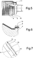
figure 5 est une vue schématique partielle et en coupe longitudinale d'un premier mode alternatif de finition de l'enroulement, - la
figure 6 est une vue schématique partielle et en coupe longitudinale d'un deuxième mode alternatif de finition de l'enroulement, - la
figure 7 est une vue schématique partielle et en coupe longitudinale d'un troisième mode alternatif de finition de l'enroulement. - En référence aux
figures 1 à 3 , le moteur électrique de l'invention comprend un stator 1, connu en lui-même, comportant une armature de conduction d'un flux magnétique. L'armature délimite un logement 2 recevant à pivotement un rotor généralement désigné en 3. - Le rotor 3 comprend un noyau 4 sensiblement cylindrique et des aimants 5, permanents, fixés en périphérie du noyau 4. Les aimants 5 sont fixés par collage dans des encoches périphériques du noyau 4. Cet agencement du noyau 4 et des aimants 5 est connu en lui-même.
- Le rotor 3 comprend en outre un fil 6 qui est enroulé à spires jointives autour du noyau 4 et des aimants 5 pour former un manchon de maintien des aimants 5 sur le noyau 4. Le fil 6 est ici enroulé sur deux couches, les spires étant jointives deux à deux au sein de chaque couche mais également d'une couche à l'autre. Le pas d'enroulement est donc égal au diamètre externe du fil 6. La tension du fil 6 est telle que le fil 6 est serré sur le noyau 4 et les aimants 5.
- Le fil 6 comprend une âme métallique 7 entourée d'une couche électriquement isolante 8 elle-même recouverte d'une gaine extérieure 9 en matériau thermo-adhérent sous forme solide. Les spires formées par le fil 6 sont fixées les unes aux autres par adhérence des portions de gaine extérieure en contact les unes avec les autres. Le fil 6 a par exemple un diamètre externe de 0,1 mm avec une couche électriquement isolante 8 et une gaine extérieure 9 ayant chacune une épaisseur de quelques micromètres. L'âme métallique 7 est ici en acier amagnétique. Ce matériau est avantageux car le noyau 4 est lui-même constitué d'acier de sorte que le fil 6 et le noyau 4 ont des coefficients de dilation identiques : il n'y a pas à tenir compte d'une éventuelle dilatation différentielle pour déterminer la tension du fil 6.
- Le fil 6 a des extrémités simplement appliquées contre le noyau 4 et fixées par adhérence des portions de gaine externe 9 en regard.
- Le manchon ainsi formé assure le maintien des aimants 5 sur le noyau 4. Bien que l'âme métallique 7 du fil 6 soit électriquement conductrice, le fil 6 ne conduit pas de courants de Foucault du fait de la gaine électriquement isolante 8.
- Le rotor de l'invention est fabriqué par la mise en oeuvre d'un procédé de fabrication comprenant les étapes de :
- fixer, ici par collage, les aimants 5 en périphérie du noyau 4,
- enrouler à spires jointives le fil 6 autour des aimants 5 et du noyau 4,
- chauffer le fil 6 pour polymériser le matériau thermo-adhérent de la gaine extérieure 9 et fixer les spires les unes aux autres par adhérence des portions de gaine extérieure 9 en contact les unes avec les autres.
- L'enroulement du fil 6 est réalisé dans une machine de bobinage. Comme le matériau thermo-adhérent de la gaine externe 9 se présente sous forme solide ou sèche, la manipulation du fil 6 est aisée, notamment au sein de la machine de bobinage.
- Le chauffage est réalisé par effet Joule en faisant passer, dans l'âme métallique 7 du fil 6, un courant électrique d'intensité adaptée. Le chauffage est ici réalisé directement dans la machine de bobinage immédiatement après la fin du bobinage. Le chauffage provoque la polymérisation du matériau thermo-adhérent qui provoque un collage des portions de gaine extérieure 9 en contact les unes avec les autres. Dans une moindre mesure, ceci entraîne également un collage des spires contre le noyau 4.
- Dans la variante de la
figure 4 , le fil 6 est enroulé sur deux couches et les spires ne sont pas jointives au sein de chaque couche. En revanche, les spires sont jointives d'une couche à l'autre, chaque spire de la couche extérieure étant supportée par deux spires adjacentes de la couche inférieure. Le pas d'enroulement doit donc être supérieur au diamètre externe du fil 6 et inférieur à deux fois le diamètre du fil 6. - Pour les variantes de réalisation des
figures 5 à 7 , le procédé comprend une étape supplémentaire d'assujettissement d'au moins une extrémité du fil 6 au noyau 4. L'assujettissement des extrémités du fil 6 permet d'éviter que les extrémités de fil 6 ne s'étendent en saillie du rotor 3. Ceci facilite les manipulations du rotor 3 et garantit une bonne maîtrise du diamètre maximal du rotor 3. - En référence à la
figure 5 , les extrémités du fil 6 sont appliquées contre une partie tronconique 10 du noyau 4 et un capot 11 sous la forme d'une bague ayant une surface interne 12 tronconique est fixé sur la partie tronconique 10 pour recouvrir les extrémités du fil 6. En variante, il peut y avoir un capot 11 pour chaque extrémité du fil 6, en particulier lorsque le nombre de couches est impair et les extrémités du fil 6 s'étendent chacune à une extrémité de l'enroulement. - En référence à la
figure 6 , chacune des extrémités du fil 6 est engagée dans un orifice 13 ménagé dans le noyau 4. L'orifice 13 peut être débouchant ou non. - En référence à la
figure 7 , chacune des extrémités du fil 6 est engagée dans trois orifices 13 ménagés dans le noyau 4 de manière à être adjacents les uns aux autres. Au moins deux des orifices 13 sont débouchants et l'extrémité du fil 6 passe dans les orifices 13 et est entrelacée entre les orifices 13 de manière à pouvoir réaliser un genre de couture assurant un assujettissement de l'extrémité de fil 6. - Bien entendu, l'invention n'est pas limitée aux modes de réalisation décrits mais englobe toute variante entrant dans le champ de l'invention telle que définie par les revendications.
- En particulier, l'âme métallique 7 peut être dans un autre métal que l'acier et par exemple en aluminium ou en cuivre. L'âme métallique 7 peut également être réalisée en acier magnétique en particulier lorsque les aimants ont une dimension circonférentielle relativement importante limitant les pertes aux interfaces : il est possible d'avoir un petit entrefer entre la partie magnétique la plus à l'extérieur du rotor 3 (à savoir le fil 6) et le stator 1.
- Le fil 6 peut être enroulé sur une couche seulement ou sur plus de deux couches.
- Le capot 11 peut avoir une autre forme que celle décrite.
- Le chauffage du fil 6 peut également être réalisé par rayonnement infrarouge, soufflage d'air chaud ou autre.
- Le chauffage du fil 6 peut être réalisé sur la machine de bobinage ou après que le noyau 4 entouré du fil 6 a été extrait de la machine de bobinage. Dans ce dernier cas, il est nécessaire de prévoir un maintien des extrémités du fil 6 pour éviter que celui-ci ne se déroule avant le chauffage.
Claims (10)
- Rotor (3) de moteur électrique, comprenant un noyau (4), des aimants (5) fixés en périphérie du noyau (4), et un fil (6) enroulé à spires jointives autour du noyau (4) et des aimants (5), le fil (6) comprend une âme métallique (7) entourée d'une couche électriquement isolante (8) elle-même recouverte d'une gaine extérieure (9) en matériau thermo-adhérent, les spires étant fixées les unes aux autres par adhérence des portions de gaine extérieure (9) en contact les unes avec les autres caractérisé par au moins une extrémité du fil (6) étant engagée dans au moins un orifice (13) ménagé dans le noyau (4).
- Rotor selon la revendication 1, dans lequel l'âme métallique (7) est en acier.
- Rotor selon la revendication 2, dans lequel l'acier est amagnétique.
- Rotor selon la revendication 1, dans lequel au moins un capot (11) est fixé sur le noyau (4) pour recouvrir au moins une extrémité du fil (6).
- Rotor selon la revendication 4, dans lequel l'extrémité du fil (6) est appliquée contre une partie tronconique (10) du noyau (4) et le capot (11) a la forme d'une bague ayant une surface interne (12) tronconique fixée sur la partie tronconique (10) pour recouvrir l'extrémités du fil (6).
- Rotor selon la revendication 1, dans lequel au moins une extrémité du fil (6) est engagée dans une pluralité d'orifices (13) ménagés dans le noyau (4).
- Procédé de fabrication d'un rotor de moteur électrique, comprenant les étapes de :- fixer des aimants en périphérie d'un noyau du rotor,- enrouler à spires jointives un fil autour des aimants et du noyau, le fil comprenant une âme métallique entourée d'une couche électriquement isolante elle-même recouverte d'une gaine extérieure en matériau thermo-adhérent sous forme solide,- chauffer le fil pour fixer les spires les unes aux autres par adhérence des portions de gaine extérieure en contact les unes avec les autres caractérisé par assujettir au moins une extrémité du fil au noyau.
- Procédé selon la revendication 7, dans lequel le chauffage est réalisé par effet Joule en faisant passer un courant électrique dans l'âme métallique du fil.
- Procédé selon la revendication 7, dans lequel l'enroulement est réalisé dans une machine de bobinage et le chauffage est réalisé dans la machine de bobinage.
- Moteur électrique comportant un stator délimitant un logement recevant à rotation un rotor conforme à l'une quelconque des revendications 1 à 6.
Applications Claiming Priority (2)
| Application Number | Priority Date | Filing Date | Title |
|---|---|---|---|
| FR1203214A FR2998731B1 (fr) | 2012-11-28 | 2012-11-28 | Rotor de moteur electrique a manchon exterieur forme par enroulement, procede de fabrication d'un tel rotor et moteur electrique comprenant un tel rotor |
| PCT/EP2013/074987 WO2014083114A1 (fr) | 2012-11-28 | 2013-11-28 | Rotor de moteur electrique a manchon exterieur forme par enroulement, procede de fabrication d'un tel rotor et moteur electrique comprenant un tel rotor |
Publications (2)
| Publication Number | Publication Date |
|---|---|
| EP2926437A1 EP2926437A1 (fr) | 2015-10-07 |
| EP2926437B1 true EP2926437B1 (fr) | 2019-01-02 |
Family
ID=48692521
Family Applications (1)
| Application Number | Title | Priority Date | Filing Date |
|---|---|---|---|
| EP13818677.0A Active EP2926437B1 (fr) | 2012-11-28 | 2013-11-28 | Rotor de moteur electrique a manchon exterieur forme par enroulement, procede de fabrication d'un tel rotor et moteur electrique comprenant un tel rotor |
Country Status (10)
| Country | Link |
|---|---|
| US (1) | US9793771B2 (fr) |
| EP (1) | EP2926437B1 (fr) |
| CN (1) | CN104823358B (fr) |
| BR (1) | BR112015012340A2 (fr) |
| CA (1) | CA2896703A1 (fr) |
| ES (1) | ES2717033T3 (fr) |
| FR (1) | FR2998731B1 (fr) |
| IL (1) | IL239033B (fr) |
| RU (1) | RU2657291C2 (fr) |
| WO (1) | WO2014083114A1 (fr) |
Families Citing this family (3)
| Publication number | Priority date | Publication date | Assignee | Title |
|---|---|---|---|---|
| CN106324085A (zh) * | 2016-08-30 | 2017-01-11 | 中国海洋石油总公司 | 一种脉冲涡流检测探头 |
| RU2728276C1 (ru) * | 2020-01-27 | 2020-07-29 | федеральное государственное бюджетное образовательное учреждение высшего образования "Уфимский государственный авиационный технический университет" | Ротор магнитоэлектрической машины с низким уровнем нагрева постоянных магнитов (варианты) |
| FR3113546B1 (fr) * | 2020-08-20 | 2022-12-23 | Safran Helicopter Engines | Machine électrique d’aéronef à transfert thermique amélioré au moyen d’un matériau à changement de phase et procédé associé |
Citations (1)
| Publication number | Priority date | Publication date | Assignee | Title |
|---|---|---|---|---|
| DE8427704U1 (de) * | 1984-09-20 | 1986-01-23 | Robert Bosch Gmbh, 7000 Stuttgart | Rotor für eine elektrische Maschine |
Family Cites Families (15)
| Publication number | Priority date | Publication date | Assignee | Title |
|---|---|---|---|---|
| JPS57177263A (en) * | 1981-04-22 | 1982-10-30 | Hitachi Ltd | Permanent magnet synchronous motor |
| JPS58163255A (ja) * | 1982-03-24 | 1983-09-28 | Okuma Mach Works Ltd | 永久磁石式同期モ−タの回転子 |
| JPS59148555A (ja) * | 1983-02-14 | 1984-08-25 | Aichi Emason Denki Kk | 回転子 |
| FR2565044B1 (fr) * | 1984-05-23 | 1987-08-28 | Labinal | Perfectionnement aux machines tournantes a aimants au rotor |
| JPS6173559A (ja) * | 1984-09-14 | 1986-04-15 | Hitachi Ltd | 永久磁石同期モ−タ−回転子 |
| US4930201A (en) | 1985-08-14 | 1990-06-05 | Kollmorgen Corporation | Method for manufacturing a composite sleeve for an electric motor |
| US4920634A (en) * | 1988-05-05 | 1990-05-01 | A. O. Smith Corporation | Permanent magnet rotor with magnet retention band |
| US5828152A (en) * | 1995-02-07 | 1998-10-27 | Denyo Kabushiki Kaisha | Rotor with permanent magnet of generator and method of manufacturing the same |
| WO2002078154A1 (fr) * | 2001-03-24 | 2002-10-03 | Lg Electronics Inc. | Ensemble d'entrainement d'un moteur alternatif et procede de fabrication correspondant |
| DE10216856B4 (de) * | 2002-04-16 | 2005-06-09 | Siemens Ag | Sicherung der Bandage eines permanentmagneterregten Läufers für eine elektrische Maschine |
| US6864614B2 (en) * | 2003-05-16 | 2005-03-08 | David Murray | Permanent magnet electric generator |
| DE102006049825B4 (de) * | 2006-10-21 | 2012-10-25 | Esw Gmbh | Anordnung zur Befestigung von Permanentmagneten an schnell drehenden Rotoren von elektrischen Maschinen |
| DE102007016771B4 (de) * | 2007-04-04 | 2009-02-12 | Esw Gmbh | Anordnung zur Befestigung von Magneten auf Rotoren von permanent erregten Synchronmaschinen |
| RU2356154C1 (ru) * | 2008-04-17 | 2009-05-20 | Андрей Борисович Захаренко | Электрическая машина с двухпакетным индуктором (варианты) |
| RU2414791C1 (ru) * | 2010-01-14 | 2011-03-20 | Владимир Михайлович Чернухин | Модульная электрическая машина |
-
2012
- 2012-11-28 FR FR1203214A patent/FR2998731B1/fr not_active Expired - Fee Related
-
2013
- 2013-11-28 WO PCT/EP2013/074987 patent/WO2014083114A1/fr not_active Ceased
- 2013-11-28 CN CN201380062238.0A patent/CN104823358B/zh active Active
- 2013-11-28 CA CA2896703A patent/CA2896703A1/fr not_active Abandoned
- 2013-11-28 BR BR112015012340A patent/BR112015012340A2/pt not_active IP Right Cessation
- 2013-11-28 EP EP13818677.0A patent/EP2926437B1/fr active Active
- 2013-11-28 RU RU2015125528A patent/RU2657291C2/ru active IP Right Revival
- 2013-11-28 ES ES13818677T patent/ES2717033T3/es active Active
- 2013-11-28 US US14/647,780 patent/US9793771B2/en active Active
-
2015
- 2015-05-27 IL IL239033A patent/IL239033B/en active IP Right Grant
Patent Citations (1)
| Publication number | Priority date | Publication date | Assignee | Title |
|---|---|---|---|---|
| DE8427704U1 (de) * | 1984-09-20 | 1986-01-23 | Robert Bosch Gmbh, 7000 Stuttgart | Rotor für eine elektrische Maschine |
Also Published As
| Publication number | Publication date |
|---|---|
| IL239033A0 (en) | 2015-07-30 |
| BR112015012340A2 (pt) | 2017-07-11 |
| WO2014083114A1 (fr) | 2014-06-05 |
| FR2998731A1 (fr) | 2014-05-30 |
| CN104823358B (zh) | 2019-03-19 |
| CA2896703A1 (fr) | 2014-06-05 |
| FR2998731B1 (fr) | 2015-12-11 |
| RU2015125528A (ru) | 2017-01-11 |
| US9793771B2 (en) | 2017-10-17 |
| RU2657291C2 (ru) | 2018-06-13 |
| CN104823358A (zh) | 2015-08-05 |
| EP2926437A1 (fr) | 2015-10-07 |
| IL239033B (en) | 2020-03-31 |
| ES2717033T3 (es) | 2019-06-18 |
| US20150326081A1 (en) | 2015-11-12 |
Similar Documents
| Publication | Publication Date | Title |
|---|---|---|
| EP0185039B1 (fr) | Perfectionnement aux machines tournantes a aimants au rotor | |
| EP0313514B1 (fr) | Procédé de fabrication d'un stator sans rainures pour moteur électrique et moteur électrique comprenant un stator fabriqué selon le procédé | |
| EP0608675B1 (fr) | Moteur électrique de puissance élevée et à vitesse de rotation élevée | |
| FR3004025A1 (fr) | Rotor discoide pour un moteur electrique a flux axial | |
| FR2861511A1 (fr) | Rotor pour une machine electrique tournante | |
| WO2010026126A1 (fr) | Stator pour machine électrique tournante et son procédé de fabrication | |
| EP2313959B1 (fr) | Rotor d'une machine électrique synchrone multipolaire à poles saillants | |
| WO2013136021A2 (fr) | Ensemble de flasques de rotor de machine electrique tournante comportant des pales axiales de ventilation favorisant un flux d'air axial a l'interieur du rotor et rotor de machine electrique associe | |
| WO2014083114A1 (fr) | Rotor de moteur electrique a manchon exterieur forme par enroulement, procede de fabrication d'un tel rotor et moteur electrique comprenant un tel rotor | |
| EP1391027B1 (fr) | Procede de fabrication d'un rotor de machine electrique tournante | |
| EP2348614A1 (fr) | Rotor de machine électrique tournante équipé d'une frette | |
| EP0793331B1 (fr) | Procédé de fabrication d'une partie tournante bobinée de machine électrique | |
| EP2297838A2 (fr) | Rotor d'une machine electrique synchrone multipolaire a piles saillants | |
| FR2988237A1 (fr) | Ensemble de flasques de rotor de machine electrique tournante munis de pions de centrage et d'evacuation de la chaleur favorisant le refroidissement du rotor et rotor de machine tournante associe | |
| WO2013093292A1 (fr) | Rotor a poles saillants comportant une piece de guidage de fils de bobinage, piece de guidage de fils de bobinage et procede de bobinage associes | |
| EP2220751A2 (fr) | Machine electrique tournante equipee de moyens de determination de la position angulaire du rotor | |
| WO2020094574A1 (fr) | Rotor a cage d'ecureuil et machine electrique asynchrone comprotant un tel rotor | |
| EP2608363B1 (fr) | Flasques de maintien des chignons de bobinages et rotor à pôles saillants comportant lesdites flasques | |
| WO2006090058A1 (fr) | Procede de fabrication d’une bobine pour un rotor d’une machine electrique tournante | |
| FR3067881A1 (fr) | Rotor pour une machine electrique tournante | |
| FR3080500A1 (fr) | Rotor de machine electrique tournante | |
| WO2013093255A2 (fr) | Rotor a pôles saillants comportant des flasques de maintien des chignons de bobinages et flasques de maintien associes | |
| EP1260992B1 (fr) | Procédé de fabrication pour un isolateur électrique composite ayant un revêtement extérieur et au moins une fibre optique les deux étant compatibles entre eux | |
| FR3083026A1 (fr) | Procede de connexion de fils sur un collecteur de moteur electrique | |
| FR2769424A1 (fr) | Moteur synchrone comportant un rotor a aimants permanents |
Legal Events
| Date | Code | Title | Description |
|---|---|---|---|
| PUAI | Public reference made under article 153(3) epc to a published international application that has entered the european phase |
Free format text: ORIGINAL CODE: 0009012 |
|
| 17P | Request for examination filed |
Effective date: 20150526 |
|
| AK | Designated contracting states |
Kind code of ref document: A1 Designated state(s): AL AT BE BG CH CY CZ DE DK EE ES FI FR GB GR HR HU IE IS IT LI LT LU LV MC MK MT NL NO PL PT RO RS SE SI SK SM TR |
|
| AX | Request for extension of the european patent |
Extension state: BA ME |
|
| DAX | Request for extension of the european patent (deleted) | ||
| RAP1 | Party data changed (applicant data changed or rights of an application transferred) |
Owner name: SAFRAN ELECTRONICS & DEFENSE |
|
| GRAP | Despatch of communication of intention to grant a patent |
Free format text: ORIGINAL CODE: EPIDOSNIGR1 |
|
| STAA | Information on the status of an ep patent application or granted ep patent |
Free format text: STATUS: GRANT OF PATENT IS INTENDED |
|
| INTG | Intention to grant announced |
Effective date: 20180718 |
|
| GRAS | Grant fee paid |
Free format text: ORIGINAL CODE: EPIDOSNIGR3 |
|
| GRAA | (expected) grant |
Free format text: ORIGINAL CODE: 0009210 |
|
| STAA | Information on the status of an ep patent application or granted ep patent |
Free format text: STATUS: THE PATENT HAS BEEN GRANTED |
|
| RIN1 | Information on inventor provided before grant (corrected) |
Inventor name: RABRET, BERNARD Inventor name: PRINCAY, GAETAN Inventor name: BESSEDE, THIERRY Inventor name: ANDRE, BRUNO Inventor name: PIATON, JEROME |
|
| AK | Designated contracting states |
Kind code of ref document: B1 Designated state(s): AL AT BE BG CH CY CZ DE DK EE ES FI FR GB GR HR HU IE IS IT LI LT LU LV MC MK MT NL NO PL PT RO RS SE SI SK SM TR |
|
| REG | Reference to a national code |
Ref country code: GB Ref legal event code: FG4D Free format text: NOT ENGLISH |
|
| REG | Reference to a national code |
Ref country code: CH Ref legal event code: EP Ref country code: AT Ref legal event code: REF Ref document number: 1085655 Country of ref document: AT Kind code of ref document: T Effective date: 20190115 |
|
| REG | Reference to a national code |
Ref country code: IE Ref legal event code: FG4D Free format text: LANGUAGE OF EP DOCUMENT: FRENCH |
|
| REG | Reference to a national code |
Ref country code: DE Ref legal event code: R096 Ref document number: 602013049306 Country of ref document: DE |
|
| REG | Reference to a national code |
Ref country code: NL Ref legal event code: MP Effective date: 20190102 |
|
| REG | Reference to a national code |
Ref country code: LT Ref legal event code: MG4D |
|
| REG | Reference to a national code |
Ref country code: AT Ref legal event code: MK05 Ref document number: 1085655 Country of ref document: AT Kind code of ref document: T Effective date: 20190102 |
|
| REG | Reference to a national code |
Ref country code: ES Ref legal event code: FG2A Ref document number: 2717033 Country of ref document: ES Kind code of ref document: T3 Effective date: 20190618 |
|
| PG25 | Lapsed in a contracting state [announced via postgrant information from national office to epo] |
Ref country code: NL Free format text: LAPSE BECAUSE OF FAILURE TO SUBMIT A TRANSLATION OF THE DESCRIPTION OR TO PAY THE FEE WITHIN THE PRESCRIBED TIME-LIMIT Effective date: 20190102 |
|
| PG25 | Lapsed in a contracting state [announced via postgrant information from national office to epo] |
Ref country code: FI Free format text: LAPSE BECAUSE OF FAILURE TO SUBMIT A TRANSLATION OF THE DESCRIPTION OR TO PAY THE FEE WITHIN THE PRESCRIBED TIME-LIMIT Effective date: 20190102 Ref country code: LT Free format text: LAPSE BECAUSE OF FAILURE TO SUBMIT A TRANSLATION OF THE DESCRIPTION OR TO PAY THE FEE WITHIN THE PRESCRIBED TIME-LIMIT Effective date: 20190102 Ref country code: PL Free format text: LAPSE BECAUSE OF FAILURE TO SUBMIT A TRANSLATION OF THE DESCRIPTION OR TO PAY THE FEE WITHIN THE PRESCRIBED TIME-LIMIT Effective date: 20190102 Ref country code: NO Free format text: LAPSE BECAUSE OF FAILURE TO SUBMIT A TRANSLATION OF THE DESCRIPTION OR TO PAY THE FEE WITHIN THE PRESCRIBED TIME-LIMIT Effective date: 20190402 Ref country code: PT Free format text: LAPSE BECAUSE OF FAILURE TO SUBMIT A TRANSLATION OF THE DESCRIPTION OR TO PAY THE FEE WITHIN THE PRESCRIBED TIME-LIMIT Effective date: 20190502 Ref country code: SE Free format text: LAPSE BECAUSE OF FAILURE TO SUBMIT A TRANSLATION OF THE DESCRIPTION OR TO PAY THE FEE WITHIN THE PRESCRIBED TIME-LIMIT Effective date: 20190102 |
|
| PG25 | Lapsed in a contracting state [announced via postgrant information from national office to epo] |
Ref country code: LV Free format text: LAPSE BECAUSE OF FAILURE TO SUBMIT A TRANSLATION OF THE DESCRIPTION OR TO PAY THE FEE WITHIN THE PRESCRIBED TIME-LIMIT Effective date: 20190102 Ref country code: HR Free format text: LAPSE BECAUSE OF FAILURE TO SUBMIT A TRANSLATION OF THE DESCRIPTION OR TO PAY THE FEE WITHIN THE PRESCRIBED TIME-LIMIT Effective date: 20190102 Ref country code: RS Free format text: LAPSE BECAUSE OF FAILURE TO SUBMIT A TRANSLATION OF THE DESCRIPTION OR TO PAY THE FEE WITHIN THE PRESCRIBED TIME-LIMIT Effective date: 20190102 Ref country code: IS Free format text: LAPSE BECAUSE OF FAILURE TO SUBMIT A TRANSLATION OF THE DESCRIPTION OR TO PAY THE FEE WITHIN THE PRESCRIBED TIME-LIMIT Effective date: 20190502 Ref country code: BG Free format text: LAPSE BECAUSE OF FAILURE TO SUBMIT A TRANSLATION OF THE DESCRIPTION OR TO PAY THE FEE WITHIN THE PRESCRIBED TIME-LIMIT Effective date: 20190402 Ref country code: GR Free format text: LAPSE BECAUSE OF FAILURE TO SUBMIT A TRANSLATION OF THE DESCRIPTION OR TO PAY THE FEE WITHIN THE PRESCRIBED TIME-LIMIT Effective date: 20190403 |
|
| REG | Reference to a national code |
Ref country code: DE Ref legal event code: R097 Ref document number: 602013049306 Country of ref document: DE |
|
| PG25 | Lapsed in a contracting state [announced via postgrant information from national office to epo] |
Ref country code: DK Free format text: LAPSE BECAUSE OF FAILURE TO SUBMIT A TRANSLATION OF THE DESCRIPTION OR TO PAY THE FEE WITHIN THE PRESCRIBED TIME-LIMIT Effective date: 20190102 Ref country code: AT Free format text: LAPSE BECAUSE OF FAILURE TO SUBMIT A TRANSLATION OF THE DESCRIPTION OR TO PAY THE FEE WITHIN THE PRESCRIBED TIME-LIMIT Effective date: 20190102 Ref country code: CZ Free format text: LAPSE BECAUSE OF FAILURE TO SUBMIT A TRANSLATION OF THE DESCRIPTION OR TO PAY THE FEE WITHIN THE PRESCRIBED TIME-LIMIT Effective date: 20190102 Ref country code: SK Free format text: LAPSE BECAUSE OF FAILURE TO SUBMIT A TRANSLATION OF THE DESCRIPTION OR TO PAY THE FEE WITHIN THE PRESCRIBED TIME-LIMIT Effective date: 20190102 Ref country code: RO Free format text: LAPSE BECAUSE OF FAILURE TO SUBMIT A TRANSLATION OF THE DESCRIPTION OR TO PAY THE FEE WITHIN THE PRESCRIBED TIME-LIMIT Effective date: 20190102 Ref country code: AL Free format text: LAPSE BECAUSE OF FAILURE TO SUBMIT A TRANSLATION OF THE DESCRIPTION OR TO PAY THE FEE WITHIN THE PRESCRIBED TIME-LIMIT Effective date: 20190102 Ref country code: EE Free format text: LAPSE BECAUSE OF FAILURE TO SUBMIT A TRANSLATION OF THE DESCRIPTION OR TO PAY THE FEE WITHIN THE PRESCRIBED TIME-LIMIT Effective date: 20190102 |
|
| PLBE | No opposition filed within time limit |
Free format text: ORIGINAL CODE: 0009261 |
|
| STAA | Information on the status of an ep patent application or granted ep patent |
Free format text: STATUS: NO OPPOSITION FILED WITHIN TIME LIMIT |
|
| PG25 | Lapsed in a contracting state [announced via postgrant information from national office to epo] |
Ref country code: SM Free format text: LAPSE BECAUSE OF FAILURE TO SUBMIT A TRANSLATION OF THE DESCRIPTION OR TO PAY THE FEE WITHIN THE PRESCRIBED TIME-LIMIT Effective date: 20190102 |
|
| 26N | No opposition filed |
Effective date: 20191003 |
|
| PG25 | Lapsed in a contracting state [announced via postgrant information from national office to epo] |
Ref country code: SI Free format text: LAPSE BECAUSE OF FAILURE TO SUBMIT A TRANSLATION OF THE DESCRIPTION OR TO PAY THE FEE WITHIN THE PRESCRIBED TIME-LIMIT Effective date: 20190102 |
|
| PG25 | Lapsed in a contracting state [announced via postgrant information from national office to epo] |
Ref country code: TR Free format text: LAPSE BECAUSE OF FAILURE TO SUBMIT A TRANSLATION OF THE DESCRIPTION OR TO PAY THE FEE WITHIN THE PRESCRIBED TIME-LIMIT Effective date: 20190102 |
|
| REG | Reference to a national code |
Ref country code: CH Ref legal event code: PL |
|
| PG25 | Lapsed in a contracting state [announced via postgrant information from national office to epo] |
Ref country code: CH Free format text: LAPSE BECAUSE OF NON-PAYMENT OF DUE FEES Effective date: 20191130 Ref country code: LU Free format text: LAPSE BECAUSE OF NON-PAYMENT OF DUE FEES Effective date: 20191128 Ref country code: MC Free format text: LAPSE BECAUSE OF FAILURE TO SUBMIT A TRANSLATION OF THE DESCRIPTION OR TO PAY THE FEE WITHIN THE PRESCRIBED TIME-LIMIT Effective date: 20190102 Ref country code: LI Free format text: LAPSE BECAUSE OF NON-PAYMENT OF DUE FEES Effective date: 20191130 |
|
| REG | Reference to a national code |
Ref country code: BE Ref legal event code: MM Effective date: 20191130 |
|
| PG25 | Lapsed in a contracting state [announced via postgrant information from national office to epo] |
Ref country code: IE Free format text: LAPSE BECAUSE OF NON-PAYMENT OF DUE FEES Effective date: 20191128 |
|
| PG25 | Lapsed in a contracting state [announced via postgrant information from national office to epo] |
Ref country code: BE Free format text: LAPSE BECAUSE OF NON-PAYMENT OF DUE FEES Effective date: 20191130 |
|
| PG25 | Lapsed in a contracting state [announced via postgrant information from national office to epo] |
Ref country code: CY Free format text: LAPSE BECAUSE OF FAILURE TO SUBMIT A TRANSLATION OF THE DESCRIPTION OR TO PAY THE FEE WITHIN THE PRESCRIBED TIME-LIMIT Effective date: 20190102 |
|
| PG25 | Lapsed in a contracting state [announced via postgrant information from national office to epo] |
Ref country code: HU Free format text: LAPSE BECAUSE OF FAILURE TO SUBMIT A TRANSLATION OF THE DESCRIPTION OR TO PAY THE FEE WITHIN THE PRESCRIBED TIME-LIMIT; INVALID AB INITIO Effective date: 20131128 Ref country code: MT Free format text: LAPSE BECAUSE OF FAILURE TO SUBMIT A TRANSLATION OF THE DESCRIPTION OR TO PAY THE FEE WITHIN THE PRESCRIBED TIME-LIMIT Effective date: 20190102 |
|
| PG25 | Lapsed in a contracting state [announced via postgrant information from national office to epo] |
Ref country code: MK Free format text: LAPSE BECAUSE OF FAILURE TO SUBMIT A TRANSLATION OF THE DESCRIPTION OR TO PAY THE FEE WITHIN THE PRESCRIBED TIME-LIMIT Effective date: 20190102 |
|
| REG | Reference to a national code |
Ref country code: FR Ref legal event code: PLFP Year of fee payment: 10 |
|
| PGFP | Annual fee paid to national office [announced via postgrant information from national office to epo] |
Ref country code: DE Payment date: 20251118 Year of fee payment: 13 |
|
| PGFP | Annual fee paid to national office [announced via postgrant information from national office to epo] |
Ref country code: GB Payment date: 20251125 Year of fee payment: 13 |
|
| PGFP | Annual fee paid to national office [announced via postgrant information from national office to epo] |
Ref country code: IT Payment date: 20251128 Year of fee payment: 13 |
|
| PGFP | Annual fee paid to national office [announced via postgrant information from national office to epo] |
Ref country code: FR Payment date: 20251125 Year of fee payment: 13 |
|
| PGFP | Annual fee paid to national office [announced via postgrant information from national office to epo] |
Ref country code: ES Payment date: 20251216 Year of fee payment: 13 |