EP2926356B1 - Switching device with several regions of connection - Google Patents
Switching device with several regions of connection Download PDFInfo
- Publication number
- EP2926356B1 EP2926356B1 EP12889388.0A EP12889388A EP2926356B1 EP 2926356 B1 EP2926356 B1 EP 2926356B1 EP 12889388 A EP12889388 A EP 12889388A EP 2926356 B1 EP2926356 B1 EP 2926356B1
- Authority
- EP
- European Patent Office
- Prior art keywords
- region
- terminals
- contactor
- auxiliary
- command
- Prior art date
- Legal status (The legal status is an assumption and is not a legal conclusion. Google has not performed a legal analysis and makes no representation as to the accuracy of the status listed.)
- Active
Links
- 230000000007 visual effect Effects 0.000 claims description 8
- 239000004020 conductor Substances 0.000 claims description 6
- 238000012423 maintenance Methods 0.000 claims description 3
- 238000000034 method Methods 0.000 claims 5
- 238000009434 installation Methods 0.000 description 3
- 238000012800 visualization Methods 0.000 description 2
- 239000003990 capacitor Substances 0.000 description 1
- 238000010292 electrical insulation Methods 0.000 description 1
- 238000005286 illumination Methods 0.000 description 1
- 238000012544 monitoring process Methods 0.000 description 1
Images


Classifications
-
- H—ELECTRICITY
- H01—ELECTRIC ELEMENTS
- H01H—ELECTRIC SWITCHES; RELAYS; SELECTORS; EMERGENCY PROTECTIVE DEVICES
- H01H50/00—Details of electromagnetic relays
- H01H50/14—Terminal arrangements
-
- H—ELECTRICITY
- H01—ELECTRIC ELEMENTS
- H01H—ELECTRIC SWITCHES; RELAYS; SELECTORS; EMERGENCY PROTECTIVE DEVICES
- H01H71/00—Details of the protective switches or relays covered by groups H01H73/00 - H01H83/00
- H01H71/08—Terminals; Connections
-
- H—ELECTRICITY
- H01—ELECTRIC ELEMENTS
- H01H—ELECTRIC SWITCHES; RELAYS; SELECTORS; EMERGENCY PROTECTIVE DEVICES
- H01H50/00—Details of electromagnetic relays
- H01H50/02—Bases; Casings; Covers
-
- H—ELECTRICITY
- H01—ELECTRIC ELEMENTS
- H01H—ELECTRIC SWITCHES; RELAYS; SELECTORS; EMERGENCY PROTECTIVE DEVICES
- H01H50/00—Details of electromagnetic relays
- H01H50/08—Indicators; Distinguishing marks
-
- H—ELECTRICITY
- H01—ELECTRIC ELEMENTS
- H01H—ELECTRIC SWITCHES; RELAYS; SELECTORS; EMERGENCY PROTECTIVE DEVICES
- H01H50/00—Details of electromagnetic relays
- H01H50/16—Magnetic circuit arrangements
- H01H50/18—Movable parts of magnetic circuits, e.g. armature
-
- H—ELECTRICITY
- H01—ELECTRIC ELEMENTS
- H01H—ELECTRIC SWITCHES; RELAYS; SELECTORS; EMERGENCY PROTECTIVE DEVICES
- H01H50/00—Details of electromagnetic relays
- H01H50/44—Magnetic coils or windings
- H01H50/443—Connections to coils
-
- H—ELECTRICITY
- H01—ELECTRIC ELEMENTS
- H01H—ELECTRIC SWITCHES; RELAYS; SELECTORS; EMERGENCY PROTECTIVE DEVICES
- H01H50/00—Details of electromagnetic relays
- H01H50/54—Contact arrangements
- H01H50/541—Auxiliary contact devices
-
- H—ELECTRICITY
- H01—ELECTRIC ELEMENTS
- H01H—ELECTRIC SWITCHES; RELAYS; SELECTORS; EMERGENCY PROTECTIVE DEVICES
- H01H50/00—Details of electromagnetic relays
- H01H50/54—Contact arrangements
- H01H50/60—Contact arrangements moving contact being rigidly combined with movable part of magnetic circuit
Definitions
- the present patent describes a multipolar electromagnetic switching device, particularly a contactor that has an upper part which houses fixed contacts, this upper body is fixed to a base, inside these both parts there is an electromagnet composed by a coil and two armatures being one fixed and the other moveable, capable of moving a contact carrier that bears the movable contacts.
- an electromagnetic switching device particularly a contactor
- the power contacts are connected to power cables through power terminals, which are connected to fixed contacts that are switched by the moveable contacts where both are in the same area.
- the command terminals are connected to the coil of the electromagnet and are situated in another region distinct of the mentioned above.
- the auxiliary contacts are connected to the auxiliary cables through the auxiliary terminals, which are connected to fixed contacts that are switched by the moveable auxiliary contacts supported by the contact carrier, and these are in another distinct region.
- the electromagnet can be positioned in the upper part or in the lower part of the contactor, being the lower part, the one that is used for fixing the contactor to a support means and the upper part the one that the cables installation tools have access to the terminals.
- the contactor presented in the patent US4,006,440 shows a constructive disposal wherein the electromagnet is arranged in the lower part of the contactor and the command terminals are arranged in a region above the coil to ease the interconnection with other dispositive, particularly an overload relay.
- the patent US3,949,333 complements the mentioned patent, showing a side mounting auxiliary contact block that is connected to the contactor and activated by cams.
- the auxiliary terminals also are arranged in a region above the power contacts and the coil.
- the patent EP1051718 granted in October 2005 and modified in October 2012 describes a contactor with the electromagnet in the lower part, wherein the disposal of the terminals is done using planes.
- the power terminals plane is above the electromagnet and above that, exists also another plane that includes the command terminals and the auxiliary terminals, wherein, they are at the same plane and disposed side by side, sequentially starting from one side of the contactor. This disposition of the terminals grouped in one extremity of the contactor makes difficult to distinguish the command terminals from the auxiliary terminals.
- the command terminals and auxiliary terminals are disposed uniformly spaced and distributed along the frame, to favor the assembly.
- the patent US3,639,866 describes an electromagnetic relay and a relay-adder combination with a constant actuating force.
- This relay has a coil at its lower part; above the coil a region for the fixed contacts and above the fixed contacts there is a region for the coil terminals. It is possible to see that since a long time there is a concern to distinguish connection terminals to prevent incorrect wiring.
- US 2011/0205003 A1 discloses an electromagnetic switching device such as a contactor with several connection regions having a plurality of command terminals and one or more auxiliary terminals.
- the electromagnetic switching device provides a visual distinction between the command terminals and the auxiliary terminals.
- US 2009/0247019 A1 discloses an expansion connection module for connecting coil connectors of an electromagnetic switching device.
- US 6,285,271 B1 discloses a capacitor switching contactor including a standard contactor, an auxiliary switch, an input terminal block, an output terminal block, and resistor wires disposed between the terminal blocks and the auxiliary switch.
- the resistor wires are connected to connecting terminals in chambers of the terminal blocks, and largely accommodated in the housing of the terminal blocks.
- Siemens, "Load Feeder Configuring SIRIUS Innovation for UL Selection data for Fuseless and Fused Load Feeders Configuration Manual - 08/2011 Industrial Controls", 31 August 2011, pages 1-58, XP055766531 discloses a contactor in which different terminals have different heights.
- the present invention is defined by the independent claims. It comprises an electromagnetic switching device, with several distinct regions, where each region separates and places the terminals and the connection means in an improved form.
- the objective of the proposed invention is to make easy the identification of the terminals for the user.
- the contactor When the contactor is fixed in the rail inside the panel, it is visible only from the top. In this manner, a level difference between the terminals cannot clearly identify the terminals; that is even worse with low illumination, commonly found in this field.
- This invention presents a clear distinction between auxiliary terminals and command terminals of the coil given by the asymmetry created for this purpose, differently of the others from state of art that don't have this distinction.
- the proposed architecture in this device creates four distinct regions, where the first region, have function of fixing the contactor on the panel and also houses the electromagnet, in a manner to make easy the coil interchange for maintenance.
- the second region that extends from the first region comprises the power terminals, which, when isolated in a distinct region, are easily connected to protection devices, such as motor circuit breaker or overload relay. This positioning also makes easy the use of connection busbars to make a reversion kit of an electric motor.
- the third region that extends from the second region houses the auxiliary and the command terminals, creating a region of control and monitoring of the device.
- the terminals are disposed asymmetrically and uneven, in the same region.
- the asymmetry grants a clear visualization and distinction between auxiliary terminals and command terminals, by putting away the command coil terminals from the auxiliary terminals; that reduces the chances of incorrect wiring.
- the uneven disposition of the terminals makes easy the use of a connection busbar, for example, a parallel busbar that can be used to energize several subsequent contactors. Additionally, the uneven disposition of the terminals provides a better distinction between auxiliary and command terminals.
- the fourth region that extends from the third region is used for the connection of front mounting accessories, such as auxiliary contact blocks, timer blocks, surge suppressor modules, and also an empty block for replacing this; includes also a groove especially designed for passing cables.
- front mounting accessories such as auxiliary contact blocks, timer blocks, surge suppressor modules, and also an empty block for replacing this; includes also a groove especially designed for passing cables.
- the multipolar contactor (1) is divided in four distinct regions.
- the first region (10) is composed by a base (11) that houses a fixed armature (12) and a coil (13) from an electromagnet.
- the base also is responsible by the fixation of the product for use. This fixation can be done using screws (not illustrated), using the holes (14), or even by rails using their connection means (15).
- the second region (20) is composed by the power terminals (21) that will receive the power conductors (not shown).
- the first region (10) is connected with the second region (20) by snap-fits (16) that belongs to the base (11) and are fitted in the holes (22), that belongs to the frames (60a) and (60b).
- the third region (30) is composed by the auxiliary terminals (31,32) that will receive the auxiliary conductors (not shown).
- the third region (30) also includes the command terminals of the coil (33), which will receive the command conductors (not shown).
- the fourth region (40) is dedicated for the connection of accessories.
- the entries (41) are used for fitting front mounting auxiliary devices, for example, a front mounting auxiliary contact block, a timer block or even a communication module.
- This region also presents a cover as an empty block (42) that in its turn can be removed for an introduction of a surge suppressor block (43).
- This block in its turn has the shape similar to the cover (42).
- the suppressor block is introduced in the cover (50) leaving its external face (51) exposed, completing the cover (50).
- the face (51) of the surge suppressor block (43) is exposed to make easy the visualization of the type of surge suppressor and posterior removal or exchange.
- the surge suppressor block (43) is fixed or removed by a snap-fit (52) that is manually actuated by the user.
- the lower part (100) of the contactor is mainly composed by the base (11), a fixed armature (12), a coil (13), snap-fits (16), and also comprises the fixing regions (14) and (15) of the contactor.
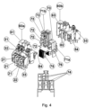
- the upper part (200) of the contactor is externally composed by the cover (50). Inside the cover, the contactor is divided in three distinct parts being these: two fixation frames (60a) and (60b) and a moveable contact carrier (70).
- the frames (60a) and (60b) have the function of housing the power terminals (21), the auxiliary terminals (31,32) and the command terminals (33). These two frames have ribs (62) that provide electrical insulation between the various live parts of the contactor.
- the frames are connected to each other using the centralizer pins (63) and snap-fits (64).
- the moveable contact carrier (70) has as main part the carrier (71a) which slides axially inside both frames, the ribs (62) of the frames are fitted inside grooves (74) limiting the movement of the carrier only axially.
- the carrier support the moveable power contacts (72) and the moveable auxiliary contacts (73). Coupled in the lower part of the carrier (70) is the moveable armature (75).
- the carrier (70) also have an aperture (76), that can be additionally used to mechanically couple a side mounting accessory, for example, a side mounting auxiliary contacts block or a mechanical interlock device.
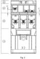
- the figure 5 shows a top view of the contactor, where is possible to visualize that in one extremity of the frame the auxiliary contact terminals (31,32) are arranged, and in the other extremity the command terminals (33) are arranged.
- the terminals are asymmetrically disposed to evidence the distinction between these terminals.
- the figure 2 is possible to visualize that further the asymmetry of the disposal of the auxiliary and the command terminals, they are clearly uneven by heights Xl and X2. This difference amplifies the distinction between the terminals, reducing the possibility of incorrect wiring. This unevenness places the command terminal above the auxiliary terminals, becoming easy to mount a busbar between these terminals, to make for example, an electrical interlock between two contactors (not shown).
Landscapes
- Physics & Mathematics (AREA)
- Electromagnetism (AREA)
- Switch Cases, Indication, And Locking (AREA)
- Magnetic Treatment Devices (AREA)
- Connections Arranged To Contact A Plurality Of Conductors (AREA)
Description
- The present patent describes a multipolar electromagnetic switching device, particularly a contactor that has an upper part which houses fixed contacts, this upper body is fixed to a base, inside these both parts there is an electromagnet composed by a coil and two armatures being one fixed and the other moveable, capable of moving a contact carrier that bears the movable contacts.
- Generally, in an electromagnetic switching device, particularly a contactor, is usual that the power contacts are connected to power cables through power terminals, which are connected to fixed contacts that are switched by the moveable contacts where both are in the same area.
- The command terminals are connected to the coil of the electromagnet and are situated in another region distinct of the mentioned above.
- The auxiliary contacts are connected to the auxiliary cables through the auxiliary terminals, which are connected to fixed contacts that are switched by the moveable auxiliary contacts supported by the contact carrier, and these are in another distinct region.
- The position of these regions can vary depending of the desired configuration and the features that are intended to provide to the final user. Depending on the chosen configuration, the electromagnet can be positioned in the upper part or in the lower part of the contactor, being the lower part, the one that is used for fixing the contactor to a support means and the upper part the one that the cables installation tools have access to the terminals.
- In this universe of conceptions related to the configuration of power, auxiliary and command terminals, the configurations and constructive arrangements are numerous aiming the ease of accessories installation and different configurations, where particularly avoid connection mistakes is one of the most important elements in contactor configuration.
- In the state of art, there are several types of contactors, with numerous arrangements of the connections regions. The most part of contactors of the market houses the electromagnet in the lower part of the contactor, this way the command terminals are disposed in the same region due the practicability and cost reduction to perform the connection. Above that, the power region and more above the region of the auxiliary terminals that can be integrated or modular in their constructive form.
- The contactor presented in the patent
US4,006,440 , shows a constructive disposal wherein the electromagnet is arranged in the lower part of the contactor and the command terminals are arranged in a region above the coil to ease the interconnection with other dispositive, particularly an overload relay. The patentUS3,949,333 , complements the mentioned patent, showing a side mounting auxiliary contact block that is connected to the contactor and activated by cams. The auxiliary terminals also are arranged in a region above the power contacts and the coil. - The patent
EP1051718 granted in October 2005 and modified in October 2012, describes a contactor with the electromagnet in the lower part, wherein the disposal of the terminals is done using planes. Given that the power terminals plane is above the electromagnet and above that, exists also another plane that includes the command terminals and the auxiliary terminals, wherein, they are at the same plane and disposed side by side, sequentially starting from one side of the contactor. This disposition of the terminals grouped in one extremity of the contactor makes difficult to distinguish the command terminals from the auxiliary terminals. - In another way, there is the patent
EP2023364 , where is described a contactor with the electromagnet in the lower part. Above the electromagnet is the power connection area and above that two areas disposed side by side, being one used for the command terminal and another slightly more elevated, used for the auxiliary terminals, where this different elevation of areas are intended to distinguish the terminals. - Additionally, according to the description of the patent
US8159321 , the command terminals and auxiliary terminals are disposed uniformly spaced and distributed along the frame, to favor the assembly. - The patent
US3,639,866 , describes an electromagnetic relay and a relay-adder combination with a constant actuating force. This relay has a coil at its lower part; above the coil a region for the fixed contacts and above the fixed contacts there is a region for the coil terminals. It is possible to see that since a long time there is a concern to distinguish connection terminals to prevent incorrect wiring. -
US 2011/0205003 A1 discloses an electromagnetic switching device such as a contactor with several connection regions having a plurality of command terminals and one or more auxiliary terminals. The electromagnetic switching device provides a visual distinction between the command terminals and the auxiliary terminals. -
US 2009/0247019 A1 discloses an expansion connection module for connecting coil connectors of an electromagnetic switching device. -
US 6,285,271 B1 discloses a capacitor switching contactor including a standard contactor, an auxiliary switch, an input terminal block, an output terminal block, and resistor wires disposed between the terminal blocks and the auxiliary switch. The resistor wires are connected to connecting terminals in chambers of the terminal blocks, and largely accommodated in the housing of the terminal blocks.
Siemens, "Load Feeder Configuring SIRIUS Innovation for UL Selection data for Fuseless and Fused Load Feeders Configuration Manual - 08/2011 Industrial Controls", 31 August 2011, pages 1-58, XP055766531, discloses a contactor in which different terminals have different heights. - The present invention is defined by the independent claims. It comprises an electromagnetic switching device, with several distinct regions, where each region separates and places the terminals and the connection means in an improved form.
- The objective of the proposed invention is to make easy the identification of the terminals for the user. When the contactor is fixed in the rail inside the panel, it is visible only from the top. In this manner, a level difference between the terminals cannot clearly identify the terminals; that is even worse with low illumination, commonly found in this field.
- This invention presents a clear distinction between auxiliary terminals and command terminals of the coil given by the asymmetry created for this purpose, differently of the others from state of art that don't have this distinction.
The proposed architecture in this device creates four distinct regions, where the first region, have function of fixing the contactor on the panel and also houses the electromagnet, in a manner to make easy the coil interchange for maintenance. - The second region that extends from the first region, comprises the power terminals, which, when isolated in a distinct region, are easily connected to protection devices, such as motor circuit breaker or overload relay. This positioning also makes easy the use of connection busbars to make a reversion kit of an electric motor.
- The third region that extends from the second region, houses the auxiliary and the command terminals, creating a region of control and monitoring of the device. Different from the other solutions, the terminals are disposed asymmetrically and uneven, in the same region. The asymmetry grants a clear visualization and distinction between auxiliary terminals and command terminals, by putting away the command coil terminals from the auxiliary terminals; that reduces the chances of incorrect wiring. The uneven disposition of the terminals makes easy the use of a connection busbar, for example, a parallel busbar that can be used to energize several subsequent contactors. Additionally, the uneven disposition of the terminals provides a better distinction between auxiliary and command terminals.
- The fourth region that extends from the third region is used for the connection of front mounting accessories, such as auxiliary contact blocks, timer blocks, surge suppressor modules, and also an empty block for replacing this; includes also a groove especially designed for passing cables. This type of division proposes advantages for installation and maintenance of these additional components, once it is above all the other regions, being the first region accessed by the user.
- It is visible, therefore, a combination of the proposed uneven disposition of the command and auxiliary terminals in the same region when viewed from the front, added with the asymmetry of the terminals when viewed from the top, which grants a doubled visual identification not characterized on the others from "state of art".
- These functional arrangements and advantages will become clearer, with the support of the drawings that will be used to illustrate the constructive details.
-
- The
figure 1 shows a perspective view, of the subdivision of the regions and defines the top view A, frontal view B, rear view D and side view C. - The
figure 2 shows a frontal view of the contactor. - The
figure 3 shows a perspective exploded view of the contactor. - The
figure 4 shows an internal exploded view of the upper part of the contactor. - The
figure 5 shows a top view of the contactor. - According to the
figures 1 to 5 , in a preferred embodiment, the multipolar contactor (1) is divided in four distinct regions. The first region (10) is composed by a base (11) that houses a fixed armature (12) and a coil (13) from an electromagnet. The base also is responsible by the fixation of the product for use. This fixation can be done using screws (not illustrated), using the holes (14), or even by rails using their connection means (15). - The second region (20) is composed by the power terminals (21) that will receive the power conductors (not shown). The first region (10) is connected with the second region (20) by snap-fits (16) that belongs to the base (11) and are fitted in the holes (22), that belongs to the frames (60a) and (60b).
- The third region (30) is composed by the auxiliary terminals (31,32) that will receive the auxiliary conductors (not shown). The third region (30) also includes the command terminals of the coil (33), which will receive the command conductors (not shown).
- The fourth region (40) is dedicated for the connection of accessories. The entries (41) are used for fitting front mounting auxiliary devices, for example, a front mounting auxiliary contact block, a timer block or even a communication module. This region also presents a cover as an empty block (42) that in its turn can be removed for an introduction of a surge suppressor block (43). This block, in its turn has the shape similar to the cover (42). The suppressor block is introduced in the cover (50) leaving its external face (51) exposed, completing the cover (50). The face (51) of the surge suppressor block (43) is exposed to make easy the visualization of the type of surge suppressor and posterior removal or exchange. The surge suppressor block (43) is fixed or removed by a snap-fit (52) that is manually actuated by the user.
- The lower part (100) of the contactor is mainly composed by the base (11), a fixed armature (12), a coil (13), snap-fits (16), and also comprises the fixing regions (14) and (15) of the contactor.
- The upper part (200) of the contactor is externally composed by the cover (50). Inside the cover, the contactor is divided in three distinct parts being these: two fixation frames (60a) and (60b) and a moveable contact carrier (70). The frames (60a) and (60b) have the function of housing the power terminals (21), the auxiliary terminals (31,32) and the command terminals (33). These two frames have ribs (62) that provide electrical insulation between the various live parts of the contactor. The frames are connected to each other using the centralizer pins (63) and snap-fits (64). The moveable contact carrier (70) has as main part the carrier (71a) which slides axially inside both frames, the ribs (62) of the frames are fitted inside grooves (74) limiting the movement of the carrier only axially. The carrier support the moveable power contacts (72) and the moveable auxiliary contacts (73). Coupled in the lower part of the carrier (70) is the moveable armature (75). The carrier (70) also have an aperture (76), that can be additionally used to mechanically couple a side mounting accessory, for example, a side mounting auxiliary contacts block or a mechanical interlock device.
- The
figure 5 shows a top view of the contactor, where is possible to visualize that in one extremity of the frame the auxiliary contact terminals (31,32) are arranged, and in the other extremity the command terminals (33) are arranged. The terminals are asymmetrically disposed to evidence the distinction between these terminals. In thefigure 2 is possible to visualize that further the asymmetry of the disposal of the auxiliary and the command terminals, they are clearly uneven by heights Xl and X2. This difference amplifies the distinction between the terminals, reducing the possibility of incorrect wiring. This unevenness places the command terminal above the auxiliary terminals, becoming easy to mount a busbar between these terminals, to make for example, an electrical interlock between two contactors (not shown).
Claims (14)
- A CONTACTOR WITH SEVERAL REGIONS OF CONNECTION having a plurality of command terminals (33) and auxiliary terminals (31, 32) wherein, the contactor (1) provides a visual distinction between the command terminals (33) and the auxiliary terminals (31, 32), the said contactor comprising:a first region (10), wherein the first region (10) includes a base (11) that is adapted for fixing the contactor (1) to a panel, and a housing that accessibly encloses an electromagnet, the electromagnet comprising a fixed armature (12) and a coil (13);a second region (20), wherein the second region (20) occupies an area located directly above the first region (10) and is releasably attached to a top of the first region (10), the second region (20) further comprising a plurality of power terminals (21), each power terminal (21) adapted to receive a power conductor, and a plurality of moveable power contacts (72), each moveable power contact (72) being associated with one of the power terminals (21) and adapted to controllably close a circuit associated with the power terminal (21); anda third region (30), wherein the third region (30) occupies an area located directly above the second region (20) and comprises the command terminals (33) and the auxiliary terminals (31, 32), the command terminals (33) being electrically connected to the coil (13),wherein the command terminals (33) are located at a first height (X1) above a bottom of the third region (30), and the auxiliary terminals (31, 32) are located at a second height (X2) above the bottom of the third region (30), the first and second heights (X1, X2) being different from each other, and wherein the command terminals (33) and the auxiliary terminals (31, 32) are disposed across the third region (30) asymmetrically, the command terminals (33) and the auxiliary terminals (31, 32) thereby presenting an asymmetry that groups the auxiliary terminals (31, 32) together and leaves the command terminals (33) standing away from the auxiliary terminals (31, 32) when viewed from the top of the third region (30), so that the command terminals (30) are visually distinguishable from the auxiliary terminals (31, 32) when viewed from the top of the third region (30),wherein the asymmetry between the auxiliary terminals and the command terminals (33) is visible when viewed from the top of the third region,the difference between the first and the second heights (X1, X2) of the command terminals and the auxiliary terminals, respectively, being visible when viewed from the front,the contactor further comprising a fourth region (40), wherein the fourth region (40) occupies an area located directly above the third region (30), the fourth region (40) being adapted for connection of accessories.
- A CONTACTOR WITH SEVERAL REGIONS OF CONNECTION, according to claim 1, the third region (30) with the first height (X1) being greater than the second height (X2) so that the command terminals (33) are located above the auxiliary terminals (31, 32) and a visual distinction is provided between the command terminals (33) and the auxiliary terminals (31, 32).
- A CONTACTOR WITH SEVERAL REGIONS OF CONNECTION, according to claim 1, the third region (30) with the second height (X2) being greater than the first height (X1) so that the auxiliary terminals (31, 32) are located above the command terminals (33) and a visual distinction is provided between the auxiliary terminals (31, 32) and the command terminals (33).
- A CONTACTOR WITH SEVERAL REGIONS OF CONNECTION according to claim 1, wherein the third region (30) of the said contactor further comprises moveable auxiliary contacts (73), each moveable auxiliary contact (73) being associated with one of the auxiliary terminals (31, 32) and adapted to controllably close a circuit associated with the auxiliary terminal (31, 32).
- A CONTACTOR WITH SEVERAL REGIONS OF CONNECTION, according to claim 2, wherein each command terminal (33) in the third region (30) is adapted for connection to a command terminal (33) of a second contactor via a busbar.
- A CONTACTOR WITH SEVERAL REGIONS OF CONNECTION, according to claim 1, wherein the second region (20) is connected to the first region (10) by snap-fits (16) that belong to the base (11) and are fitted in holes (22), that release-ably connect to the housing of the first region (10), and wherein the housing of the first region (10) provides access to the electromagnet so that the coil (13) can be replaced for maintenance.
- A CONTACTOR WITH SEVERAL REGIONS OF CONNECTION according to claim 1, wherein the third region (30) comprises a plurality of command terminals (33), each command terminal (33) adapted to receive a command conductor.
- A CONTACTOR WITH SEVERAL REGIONS OF CONNECTION, according to claim 1, wherein the second region (20) further comprises a moveable carrier support (71a) that houses and limits the movement of the moveable power contacts (72).
- A CONTACTOR WITH SEVERAL REGIONS OF CONNECTION, according to claim 1, wherein the third region (30) further comprises a second carrier support (71b) that houses and limits the movement of the moveable auxiliary contacts (73).
- A CONTACTOR WITH SEVERAL REGIONS OF CONNECTION, according to claim 1, wherein the fourth region (40) presents a cover as an empty block (42) that can be removed for an introduction of a surge suppressor block (43).
- A CONTACTOR WITH SEVERAL REGIONS OF CONNECTION, according to claim 1, wherein the fourth region (40) is configured to receive a front mounting auxiliary contact block, a timer or a communication module.
- A METHOD FOR USE IN A CONTACTOR WITH SEVERAL REGIONS OF CONNECTION having a plurality of command terminals (33) and auxiliary terminals (31, 32), wherein the contactor (1) provides a visual distinction between the command terminals (33) and the auxiliary terminals (31, 32), the method comprising:providing a first region (10) on the contactor (1), wherein the first region (10) includes a base (11) that is adapted for fixing the contactor (1) to a panel, and a housing that accessibly encloses an electromagnet, the electromagnet comprising a fixed armature (12) and a coil (13);providing a second region (20) on the contactor (1), wherein the second region (20) occupies an area located directly above the first region (10) and is releasably attached to a top of the first region (10), the second region (20) further comprising a plurality of power terminals (21), each power terminal (21) adapted to receive a power conductor, and a plurality of moveable power contacts (72), each moveable power contact (72) being associated with one of the power terminals (21) and adapted to controllably close a circuit associated with the associated power terminal (21);providing a third region (30) on the contactor (1), wherein the third region (30) occupies an area located directly above the second region (20) and comprises the command terminals (33) and the auxiliary terminals (31, 32), the command terminals (33) being electrically connected to the coil (13) and located at a first height (X1) above a bottom of the third region (30), and the auxiliary terminals (31, 32) being located at a second height (X2) above the bottom of the third region (30), the first and second heights (X1, X2) being different from each other, and wherein the command terminals (33) and the auxiliary terminals (31, 32) are disposed across the third region (30) asymmetrically, the command terminals (33) and the auxiliary terminals (31, 32) thereby presenting an asymmetry that groups the auxiliary terminals (31, 32) together and leaves the command terminals (33) standing away so that the command terminals are visually distinguishable from the auxiliary terminals (31, 32) when viewed from a top of the third region (30),wherein the asymmetry between the auxiliary terminals and the command terminals (33) is visible when viewed from the top of the third region, the difference between the first and the second heights (X1, X2) of the command terminals and the auxiliary terminals, respectively, being visible when viewed from the front,providing a fourth region (40) on the contactor (1), wherein the fourth region (40) occupies an area located directly above the third region (30), the fourth region (40) being adapted for connection of accessories.
- A METHOD FOR USE IN A CONTACTOR WITH SEVERAL REGIONS OF CONNECTION, according to claim 12, wherein the first height (X1) is greater than the second height (X2) so that the command terminals (33) are located above the auxiliary terminals (31, 32) and a visual distinction is provided between the command terminals (33) and the auxiliary terminals (31, 32).
- A METHOD FOR USE IN A CONTACTOR WITH SEVERAL REGIONS OF CONNECTION, according to claim 12, wherein the said method comprises providing the third region (30) with the second height (X2) being greater than the first height (X1) so that the auxiliary terminals (31, 32) are located above the command terminals (33) and a visual distinction is provided between the auxiliary terminals (31, 32) and the command terminals (33).
Applications Claiming Priority (1)
| Application Number | Priority Date | Filing Date | Title |
|---|---|---|---|
| PCT/BR2012/000488 WO2014082144A1 (en) | 2012-11-29 | 2012-11-29 | Switching device with several regions of connection |
Publications (4)
| Publication Number | Publication Date |
|---|---|
| EP2926356A1 EP2926356A1 (en) | 2015-10-07 |
| EP2926356A4 EP2926356A4 (en) | 2016-08-10 |
| EP2926356B1 true EP2926356B1 (en) | 2024-03-27 |
| EP2926356C0 EP2926356C0 (en) | 2024-03-27 |
Family
ID=50826971
Family Applications (1)
| Application Number | Title | Priority Date | Filing Date |
|---|---|---|---|
| EP12889388.0A Active EP2926356B1 (en) | 2012-11-29 | 2012-11-29 | Switching device with several regions of connection |
Country Status (5)
| Country | Link |
|---|---|
| US (1) | US9601290B2 (en) |
| EP (1) | EP2926356B1 (en) |
| CN (1) | CN104520960B (en) |
| BR (1) | BR112015005762B1 (en) |
| WO (1) | WO2014082144A1 (en) |
Families Citing this family (7)
| Publication number | Priority date | Publication date | Assignee | Title |
|---|---|---|---|---|
| FR2999791B1 (en) * | 2012-12-18 | 2015-01-02 | Schneider Electric Ind Sas | MODULAR ELECTRICAL SWITCHING DEVICE COMPRISING AT LEAST ONE UNIPOLAR CUT-OFF BLOCK AND SWITCHING ARRANGEMENT HAVING SUCH DEVICES |
| JP6176364B1 (en) * | 2016-06-14 | 2017-08-09 | 富士電機機器制御株式会社 | Contact device and electromagnetic contactor using the same |
| CN107591289B (en) * | 2016-07-08 | 2019-12-27 | 浙江正泰电器股份有限公司 | Contactor |
| JP6332480B1 (en) * | 2017-01-11 | 2018-05-30 | 富士電機機器制御株式会社 | Magnetic contactor |
| CN113035646A (en) * | 2019-12-24 | 2021-06-25 | 施耐德电器工业公司 | Modular contactor |
| CN112992609A (en) * | 2021-02-26 | 2021-06-18 | 神华准格尔能源有限责任公司 | Electric control contactor |
| WO2022198286A1 (en) | 2021-03-26 | 2022-09-29 | Weg Drives & Controls - Automação Ltda. | Switching device using assembly of two-part moveable head with built-in main and auxiliary electrical conductors |
Citations (1)
| Publication number | Priority date | Publication date | Assignee | Title |
|---|---|---|---|---|
| US6285271B1 (en) * | 1997-07-10 | 2001-09-04 | Siemens Aktiengesellschaft | Capacitor switching contactor |
Family Cites Families (15)
| Publication number | Priority date | Publication date | Assignee | Title |
|---|---|---|---|---|
| US3296567A (en) * | 1964-05-25 | 1967-01-03 | Westinghouse Electric Corp | Electric control device |
| US3639866A (en) | 1970-10-12 | 1972-02-01 | Honeywell Inc | Constant actuating force arrangement for a relay and a relay-adder combination |
| US3949333A (en) | 1974-07-12 | 1976-04-06 | Allen-Bradley Company | Auxiliary switch for electromagnetic contactor |
| US4006440A (en) | 1975-07-21 | 1977-02-01 | Allen-Bradley Company | Terminal structure for electromagnetic contactor |
| DZ2952A1 (en) * | 1998-12-01 | 2004-03-15 | Schneider Electric Ind Sa | Electromechanical collector housing an electromagnet and a movable contact carrier in a body. |
| US6232859B1 (en) | 2000-03-15 | 2001-05-15 | General Electric Company | Auxiliary switch mounting configuration for use in a molded case circuit breaker |
| FR2818435B1 (en) * | 2000-12-18 | 2003-10-31 | Schneider Electric Ind Sa | ASSEMBLY OF ELECTRICAL DEVICES FOR CONTROLLING POWER DEVICES |
| FR2830677B1 (en) * | 2001-10-09 | 2004-05-28 | Schneider Electric Ind Sa | FUNCTIONAL ELECTRIC MODULE FOR CONTROLLING LOADS SUCH AS MOTORS |
| DE102004009650B3 (en) * | 2004-02-27 | 2005-07-07 | Moeller Gmbh | Protection switch with upper part of main housing having stepped-back edge fitted with termination module with control clamps connected to magnetic coil of electromagnetic drive in housing lower part |
| DE102005040348B4 (en) * | 2005-08-25 | 2008-01-17 | Siemens Ag | Connection system with an electromagnetic switching device, in particular contactor, and a plug |
| FR2907963B1 (en) * | 2006-10-27 | 2009-01-09 | Abb Entrelec Soc Par Actions S | ELECTRICAL CONNECTION MODULE BETWEEN A FIRST AND A SECOND CONTACTOR AND CORRESPONDING INVERTER MOUNTING |
| FR2908233B1 (en) | 2006-11-02 | 2009-01-09 | Abb Entrelec Soc Par Actions S | CONTACTOR WITH MODULAR CONNECTION OF THE COIL |
| DE102007017516B3 (en) * | 2007-04-13 | 2008-04-30 | Siemens Ag | Electromagnetic switching device e.g. contactor, manufacturing method, involves fixing main coverings in switching chamber, so that main coverings cover main counter contact points and fix separation units in switching chamber |
| ATE528776T1 (en) * | 2007-08-07 | 2011-10-15 | Siemens Ag | ELECTROMAGNETIC SWITCHING DEVICE WITH SEVERAL AREAS GRADUATED RELATIVELY TO EACH OTHER |
| EP2107580A1 (en) * | 2008-04-01 | 2009-10-07 | Siemens Aktiengesellschaft | Expansion attachment module for attachment to at least two spool connections of an electromagnetic switching device, in particular a switch |
-
2012
- 2012-11-29 CN CN201280075105.2A patent/CN104520960B/en active Active
- 2012-11-29 BR BR112015005762-4A patent/BR112015005762B1/en active IP Right Grant
- 2012-11-29 WO PCT/BR2012/000488 patent/WO2014082144A1/en active Application Filing
- 2012-11-29 EP EP12889388.0A patent/EP2926356B1/en active Active
- 2012-11-29 US US14/428,420 patent/US9601290B2/en active Active - Reinstated
Patent Citations (1)
| Publication number | Priority date | Publication date | Assignee | Title |
|---|---|---|---|---|
| US6285271B1 (en) * | 1997-07-10 | 2001-09-04 | Siemens Aktiengesellschaft | Capacitor switching contactor |
Non-Patent Citations (1)
| Title |
|---|
| SIEMENS: "Load Feeder Configuring SIRIUS Innovations for UL Selection data for Fuseless and Fused Load Feeders Configuration Manual - 08/2011 Industrial Controls", 31 August 2011 (2011-08-31), pages 1 - 58, XP055766531, Retrieved from the Internet <URL:https://support.industry.siemens.com/cs/document/53433538/configuration-manual-configuring-sirius-innovations-for-ul-selection-data-for-fuseless-and-fused-load-feeders?dti=0&lc=en-WW> [retrieved on 20210119] * |
Also Published As
| Publication number | Publication date |
|---|---|
| EP2926356A1 (en) | 2015-10-07 |
| BR112015005762B1 (en) | 2022-05-10 |
| EP2926356A4 (en) | 2016-08-10 |
| US20150248983A1 (en) | 2015-09-03 |
| CN104520960B (en) | 2018-04-20 |
| CN104520960A (en) | 2015-04-15 |
| WO2014082144A1 (en) | 2014-06-05 |
| EP2926356C0 (en) | 2024-03-27 |
| US9601290B2 (en) | 2017-03-21 |
| BR112015005762A2 (en) | 2017-07-04 |
Similar Documents
| Publication | Publication Date | Title |
|---|---|---|
| EP2926356B1 (en) | Switching device with several regions of connection | |
| US7417848B2 (en) | Multiple height, high density horizontal low voltage motor control center | |
| US11088514B2 (en) | Power distributor | |
| EP1964222B1 (en) | Power distribution system with individually isolatable functional zones | |
| CA2723661C (en) | Configurable deadfront fusible panelboard | |
| US20100008023A1 (en) | Multiphase line fuse module | |
| US5516992A (en) | Transformer tap changing and step switch assembly | |
| KR100973944B1 (en) | The plug for the cabinet panel | |
| US5705862A (en) | Configurable panelboard for a plurality of electrical switching apparatus | |
| CN108879540B (en) | Power distribution system and method of assembling power distribution system | |
| KR920001793A (en) | switchboard | |
| KR101369370B1 (en) | Electromagnetic switching device having a plurality of areas graduated relative to one another | |
| CA2298642C (en) | Modular protective relay with submodules | |
| US9263860B2 (en) | Power distribution system, and switchgear assembly, and mounting member therefor | |
| EP1346387B1 (en) | Supporting base for a circuit breaker | |
| KR101290048B1 (en) | Switch cabinet for operating a medium-voltage or high-voltage switchgear | |
| CN107068497B (en) | Device with the switch for controlling power | |
| JP2006149118A (en) | Interrupting device for low-voltage power distribution | |
| US11996678B2 (en) | Switching and/or distributing device | |
| PL179204B1 (en) | Apparatus for connecting an electric wiring system equipment | |
| EP2628168B1 (en) | Rocker switch unit | |
| GB2131632A (en) | Electric plugs | |
| JP2006079926A (en) | Terminal stand for breaker and distribution board having a plurality of primary feeding breakers | |
| PL196532B1 (en) | Switchpanel for circuit breakers, with a device compartment and a cable terminal compartment | |
| JP2017135939A (en) | Distribution board and bus bar |
Legal Events
| Date | Code | Title | Description |
|---|---|---|---|
| PUAI | Public reference made under article 153(3) epc to a published international application that has entered the european phase |
Free format text: ORIGINAL CODE: 0009012 |
|
| 17P | Request for examination filed |
Effective date: 20150316 |
|
| AK | Designated contracting states |
Kind code of ref document: A1 Designated state(s): AL AT BE BG CH CY CZ DE DK EE ES FI FR GB GR HR HU IE IS IT LI LT LU LV MC MK MT NL NO PL PT RO RS SE SI SK SM TR |
|
| AX | Request for extension of the european patent |
Extension state: BA ME |
|
| DAX | Request for extension of the european patent (deleted) | ||
| RIN1 | Information on inventor provided before grant (corrected) |
Inventor name: DETLEV GUENTHER, IVO Inventor name: DE BARROS ALBUQUERQUE, ANDRE Inventor name: BERNARDI ROSSO, JULIANO Inventor name: VETORE, LEONARDO LUIZ |
|
| RA4 | Supplementary search report drawn up and despatched (corrected) |
Effective date: 20160713 |
|
| RIC1 | Information provided on ipc code assigned before grant |
Ipc: H01H 50/14 20060101AFI20160707BHEP Ipc: H01H 50/08 20060101ALI20160707BHEP Ipc: H01H 71/08 20060101ALI20160707BHEP Ipc: H01H 50/54 20060101ALI20160707BHEP Ipc: H01H 50/02 20060101ALI20160707BHEP |
|
| STAA | Information on the status of an ep patent application or granted ep patent |
Free format text: STATUS: EXAMINATION IS IN PROGRESS |
|
| 17Q | First examination report despatched |
Effective date: 20180315 |
|
| STAA | Information on the status of an ep patent application or granted ep patent |
Free format text: STATUS: EXAMINATION IS IN PROGRESS |
|
| STAA | Information on the status of an ep patent application or granted ep patent |
Free format text: STATUS: EXAMINATION IS IN PROGRESS |
|
| GRAP | Despatch of communication of intention to grant a patent |
Free format text: ORIGINAL CODE: EPIDOSNIGR1 |
|
| STAA | Information on the status of an ep patent application or granted ep patent |
Free format text: STATUS: GRANT OF PATENT IS INTENDED |
|
| INTG | Intention to grant announced |
Effective date: 20231013 |
|
| GRAS | Grant fee paid |
Free format text: ORIGINAL CODE: EPIDOSNIGR3 |
|
| GRAA | (expected) grant |
Free format text: ORIGINAL CODE: 0009210 |
|
| STAA | Information on the status of an ep patent application or granted ep patent |
Free format text: STATUS: THE PATENT HAS BEEN GRANTED |
|
| AK | Designated contracting states |
Kind code of ref document: B1 Designated state(s): AL AT BE BG CH CY CZ DE DK EE ES FI FR GB GR HR HU IE IS IT LI LT LU LV MC MK MT NL NO PL PT RO RS SE SI SK SM TR |
|
| REG | Reference to a national code |
Ref country code: GB Ref legal event code: FG4D |
|
| REG | Reference to a national code |
Ref country code: CH Ref legal event code: EP |
|
| REG | Reference to a national code |
Ref country code: DE Ref legal event code: R096 Ref document number: 602012080652 Country of ref document: DE |
|
| REG | Reference to a national code |
Ref country code: IE Ref legal event code: FG4D |
|
| U01 | Request for unitary effect filed |
Effective date: 20240423 |
|
| U07 | Unitary effect registered |
Designated state(s): AT BE BG DE DK EE FI FR IT LT LU LV MT NL PT SE SI Effective date: 20240430 |
|
| PG25 | Lapsed in a contracting state [announced via postgrant information from national office to epo] |
Ref country code: RS Free format text: LAPSE BECAUSE OF FAILURE TO SUBMIT A TRANSLATION OF THE DESCRIPTION OR TO PAY THE FEE WITHIN THE PRESCRIBED TIME-LIMIT Effective date: 20240627 Ref country code: HR Free format text: LAPSE BECAUSE OF FAILURE TO SUBMIT A TRANSLATION OF THE DESCRIPTION OR TO PAY THE FEE WITHIN THE PRESCRIBED TIME-LIMIT Effective date: 20240327 |
|
| PG25 | Lapsed in a contracting state [announced via postgrant information from national office to epo] |
Ref country code: RS Free format text: LAPSE BECAUSE OF FAILURE TO SUBMIT A TRANSLATION OF THE DESCRIPTION OR TO PAY THE FEE WITHIN THE PRESCRIBED TIME-LIMIT Effective date: 20240627 Ref country code: NO Free format text: LAPSE BECAUSE OF FAILURE TO SUBMIT A TRANSLATION OF THE DESCRIPTION OR TO PAY THE FEE WITHIN THE PRESCRIBED TIME-LIMIT Effective date: 20240627 Ref country code: HR Free format text: LAPSE BECAUSE OF FAILURE TO SUBMIT A TRANSLATION OF THE DESCRIPTION OR TO PAY THE FEE WITHIN THE PRESCRIBED TIME-LIMIT Effective date: 20240327 |