EP2926150B1 - Cantilever contact probe for a testing head - Google Patents
Cantilever contact probe for a testing head Download PDFInfo
- Publication number
- EP2926150B1 EP2926150B1 EP13814035.5A EP13814035A EP2926150B1 EP 2926150 B1 EP2926150 B1 EP 2926150B1 EP 13814035 A EP13814035 A EP 13814035A EP 2926150 B1 EP2926150 B1 EP 2926150B1
- Authority
- EP
- European Patent Office
- Prior art keywords
- contact
- probe
- probes
- size
- cantilever
- Prior art date
- Legal status (The legal status is an assumption and is not a legal conclusion. Google has not performed a legal analysis and makes no representation as to the accuracy of the status listed.)
- Not-in-force
Links
- 239000000523 sample Substances 0.000 title claims description 283
- 238000012360 testing method Methods 0.000 title claims description 122
- 238000005452 bending Methods 0.000 claims description 22
- 239000011347 resin Substances 0.000 claims description 11
- 229920005989 resin Polymers 0.000 claims description 11
- 239000011295 pitch Substances 0.000 description 20
- 239000000463 material Substances 0.000 description 6
- 238000003825 pressing Methods 0.000 description 5
- 230000003247 decreasing effect Effects 0.000 description 4
- 229910052782 aluminium Inorganic materials 0.000 description 3
- XAGFODPZIPBFFR-UHFFFAOYSA-N aluminium Chemical compound [Al] XAGFODPZIPBFFR-UHFFFAOYSA-N 0.000 description 3
- 239000000919 ceramic Substances 0.000 description 3
- 238000004140 cleaning Methods 0.000 description 3
- 238000005201 scrubbing Methods 0.000 description 3
- 230000001276 controlling effect Effects 0.000 description 2
- 238000005516 engineering process Methods 0.000 description 2
- 238000004519 manufacturing process Methods 0.000 description 2
- XUIMIQQOPSSXEZ-UHFFFAOYSA-N Silicon Chemical compound [Si] XUIMIQQOPSSXEZ-UHFFFAOYSA-N 0.000 description 1
- 239000000956 alloy Substances 0.000 description 1
- 229910045601 alloy Inorganic materials 0.000 description 1
- 230000015572 biosynthetic process Effects 0.000 description 1
- 230000001680 brushing effect Effects 0.000 description 1
- 230000015556 catabolic process Effects 0.000 description 1
- 238000005520 cutting process Methods 0.000 description 1
- 230000002950 deficient Effects 0.000 description 1
- 238000006731 degradation reaction Methods 0.000 description 1
- 238000001514 detection method Methods 0.000 description 1
- 238000009413 insulation Methods 0.000 description 1
- 229910052751 metal Inorganic materials 0.000 description 1
- 239000002184 metal Substances 0.000 description 1
- 238000000034 method Methods 0.000 description 1
- 230000001105 regulatory effect Effects 0.000 description 1
- 229910052710 silicon Inorganic materials 0.000 description 1
- 239000010703 silicon Substances 0.000 description 1
- 230000003313 weakening effect Effects 0.000 description 1
Images




Classifications
-
- G—PHYSICS
- G01—MEASURING; TESTING
- G01R—MEASURING ELECTRIC VARIABLES; MEASURING MAGNETIC VARIABLES
- G01R1/00—Details of instruments or arrangements of the types included in groups G01R5/00 - G01R13/00 and G01R31/00
- G01R1/02—General constructional details
- G01R1/06—Measuring leads; Measuring probes
- G01R1/067—Measuring probes
- G01R1/06711—Probe needles; Cantilever beams; "Bump" contacts; Replaceable probe pins
- G01R1/06716—Elastic
- G01R1/06727—Cantilever beams
-
- G—PHYSICS
- G01—MEASURING; TESTING
- G01R—MEASURING ELECTRIC VARIABLES; MEASURING MAGNETIC VARIABLES
- G01R1/00—Details of instruments or arrangements of the types included in groups G01R5/00 - G01R13/00 and G01R31/00
- G01R1/02—General constructional details
- G01R1/04—Housings; Supporting members; Arrangements of terminals
-
- G—PHYSICS
- G01—MEASURING; TESTING
- G01R—MEASURING ELECTRIC VARIABLES; MEASURING MAGNETIC VARIABLES
- G01R1/00—Details of instruments or arrangements of the types included in groups G01R5/00 - G01R13/00 and G01R31/00
- G01R1/02—General constructional details
- G01R1/06—Measuring leads; Measuring probes
- G01R1/067—Measuring probes
- G01R1/073—Multiple probes
- G01R1/07307—Multiple probes with individual probe elements, e.g. needles, cantilever beams or bump contacts, fixed in relation to each other, e.g. bed of nails fixture or probe card
- G01R1/07342—Multiple probes with individual probe elements, e.g. needles, cantilever beams or bump contacts, fixed in relation to each other, e.g. bed of nails fixture or probe card the body of the probe being at an angle other than perpendicular to test object, e.g. probe card
-
- G—PHYSICS
- G01—MEASURING; TESTING
- G01R—MEASURING ELECTRIC VARIABLES; MEASURING MAGNETIC VARIABLES
- G01R1/00—Details of instruments or arrangements of the types included in groups G01R5/00 - G01R13/00 and G01R31/00
- G01R1/02—General constructional details
- G01R1/06—Measuring leads; Measuring probes
- G01R1/067—Measuring probes
- G01R1/06711—Probe needles; Cantilever beams; "Bump" contacts; Replaceable probe pins
- G01R1/06733—Geometry aspects
Definitions
- a testing head is essentially a device for electrically connecting a plurality of contact pads of a micro-structure (such as an integrated circuit or generally an electronic device) to corresponding channels of a testing apparatus or machine which has to test the same.
- a micro-structure such as an integrated circuit or generally an electronic device
- a cantilever testing head of the known type usually supports a plurality of flexible, generally rod-like probes, having predetermined electrical and mechanical properties.
- the probes, which protrude from the cantilever testing head, have a substantially hook-shaped form, because of an end section essentially having an elbow bend with an inner obtuse angle.
- a good connection between the contact probes 4 of the testing head 1 and the contact pads 7 of the device under test 8 is ensured by a pressure of the testing head 1 against the same device, wherein the contact probes 4 are subject to a vertical bending directed in an opposite direction with respect to the movement of the device towards the head.
- the sliding movement or scrubbing of the contact tips 6 over the pads 7 should allow a durable and optimal electrical contact between the probes 4 and the pads 7 of the device under test 8.
- a low value of scrub mark is indicative of a low invasiveness of a test, thus reducing damages to the contact pads 7 caused by the tips of the contact probes 4, and this in turn allows for a good quality of the following connection (bonding) with such pads.
- testing heads also have intrinsic limits regarding the distance between two adjacent or contiguous probes, i.e. the center-to-center distance between two adjacent contact pads 7 of the device under test 8, indicated as “pitch" in the field.
- the minimum value of "pitch" of the pads which may be tested varies according to the geometric conditions and the size of the probes.
- the testing head 1 has to comply with the following relationship: PL > fc + S wherein:
- the diameter fc of the contact probes 4 is usually taken into account, since such probes are normally formed by metal wires with a circular cross section. More generally, the probe's diameter is understood as the maximum dimension of its section perpendicular to a longitudinal extension axis of the same probe, which, according to the previous definitions, is considered as extending along the side by side placing direction of the probes, i.e. where they can contact each other.
- N fc + S / P rounded to the next higher integer .
- the problem caused by collision of probes has evidently a three-dimensional character.
- the sites with the greatest risk of contact are the bending points PG of a probe at a level corresponding to a slightly tapered area of the hook-shaped end portion 4A of adjacent contact probes 4.
- the probe of level 11 having a hook length of L1
- the probe of level 12 produces a shorter scrub mark with respect to the probe at level 12, having a hook length L2, which in turn is shorter than the one generated by the probe on level 13, having a hook length L3.
- the first area of the probe at the reduced portion has a second size along the orthogonal direction with respect to the side by side placing direction of the probes which is greater than the first size.
- the contact tip may comprise a corrugated contact portion.
- the value of the second size of the first section at the reduced portion may be chosen according to a current that the probe should sustain.
- the value of the first size of the first area at the reduced portion may vary between 25 ⁇ m and 200 ⁇ m and the value of the first size of the second area may vary between 50 ⁇ m and 300 ⁇ m.
- the value of the first size of the first area at the reduced portion may vary between 20 ⁇ m and 180 ⁇ m and the value of the first size of the second area may vary between 30 ⁇ m and 200 ⁇ m.
- the value of the second size of the first area at the reduced portion may vary between 50 ⁇ m and 400 ⁇ m.
- FIG. 3A a cantilever contact probe according to the prior art ( Figure 3A ) and a cantilever contact probe according to an embodiment of the invention ( Figure 4A ) are schematically shown.
- a cantilever contact probe according to the invention shown in Figure 4A generally indicated in 20, comprises a probe body 21 and an end portion 22, joined to the probe body 21 and ending with a slanted hook-shaped section 23.
- the end portion 22 is bent at a bending point 24 with a suitable inclination of the slanted hook-shaped section 23, with respect to a longitudinal extension axis of the probe body 21, and ending with a contact tip 25, for contacting a plurality of contact pads 7 of a device under test.
- the cantilever contact probe 20 has a reduced portion 26, which is in particular provided in a section of the probe body 21 adjoining the end portion 22, having a first area A1 shown in Figure 4B , taken in correspondence of a first transversal plane ⁇ of Figure 4A with a first size B, in particular, a maximum size in the side by side direction of the probes Dir, and a second size H, in particular, a maximum size in a direction perpendicular to the side by side direction of the probes Dir.
- the first size B is the thickness of the reduced portion 26 of the cantilever contact probe 20 and the second size H is its height.
- the second size H is greater than the first size B.
- the contact tip 25 may also have a contact portion, which is suitably corrugated, in order to abut against a covering layer or film (oxide or dirt in general) overlaying the contact pad of the device under test.
- the hook-shaped end portion 22 of the cantilever contact probe 20 according to the invention therefore deforms during such pressing contact against the contact pad, wherein its horizontal movement or scrub against the same pad is limited by the corrugated contact portion being stuck on the covering layer of the contact pads.
- the cantilever contact probes 20 may be more narrowly spaced in the further resin support 28, with respect to cantilever contact probes 10 made according to prior art, due to the reduced size precisely in the side by side direction of the probes Dir, in particular the first size B of the first area A1 at the reduced portion 26.
- distance P1 between the contact tips 15 of cantilever contact probes 10 according to prior art is greater than distance P2 between the contact tips 25 of the cantilever contact probes 20 according to the invention, having both the same safety distance S between probes.
- the cantilever contact probes 20 are able to contact pads, whose distance between centers, or pitch, is less than the pitch of the cantilever contact probes 10 of the known type (P2 ⁇ P1).
- a testing head 30 may be provided which has a lower number of levels with respect to those used in the prior art for testing the same device, wherein each level of cantilever contact probes 20 may contact a higher number of contact pads, thanks to the reduced distance between the respective contact tips 25.
- the provision of the reduced portion 26' in the end portion 22 improves the elastic properties of such end portion 22 and of the cantilever contact probe 20 as a whole, also allowing a reduction of the length of the slanted sections 23.
- testing head 30' comprising at least one level 11 of cantilever contact probes 20' according to the embodiment of Figure 6 is such as to allow the testing of devices with smaller pitch with respect to a traditional testing head only comprising cantilever contact probes 10 of Figure 3A .
- a cantilever contact probe for example a probe 20 as shown in Figure 4A , may have a first size B1 of its first area A1 at its reduced portion 26, sufficient to contact a device having a first pitch P1.
Landscapes
- Physics & Mathematics (AREA)
- General Physics & Mathematics (AREA)
- Measuring Leads Or Probes (AREA)
- Testing Or Measuring Of Semiconductors Or The Like (AREA)
- Geometry (AREA)
- Measurement Of Length, Angles, Or The Like Using Electric Or Magnetic Means (AREA)
- Length Measuring Devices With Unspecified Measuring Means (AREA)
- Testing Of Individual Semiconductor Devices (AREA)
- Tests Of Electronic Circuits (AREA)
Description
- The present invention refers to a cantilever contact probe for a testing head.
- More in particular, the invention refers to a cantilever contact probe having at least a probe body and a hook-shaped end portion, which is slanted starting at a bending point with respect to the probe body and ending with a contact tip for ensuring a mechanical and electrical contact with a contact pad of a device under test.
- The invention also refers to a testing head comprising a plurality of cantilever contact probes.
- As is known, a testing head is essentially a device for electrically connecting a plurality of contact pads of a micro-structure (such as an integrated circuit or generally an electronic device) to corresponding channels of a testing apparatus or machine which has to test the same.
- The test, which is performed on integrated circuits, allows the detection and insulation of defective circuits, yet in the production phase. Normally, testing heads are therefore used for electrical testing of wafer based electrical circuits, prior to cutting and assembling the same inside a chip containment package.
- It is therefore known that the efficiency and reliability of a measuring test relies, among other things, on the provision of a good electrical connection between the microstructure, or in general a device under test, and testing apparatus, and therefore, an optimal electrical contact between probe and pad.
- It is also known that the electrical connection testing apparatus/device and hence probe/pad, though originally good, may with time undergo a substantial degradation and possibly vanish, because of dirt deposits and oxide formation on the contact pads of the device under test.
- For ensuring the reliability and efficiency of a measuring test, it is therefore necessary to provide a "cleaning" of said contact pads.
- Among the testing heads used in this particular technical field, for testing integrated circuits, the so called cantilever probe testing heads, which are provided with cantilevered probes, similar to fishing rods suspended over the device under test, are widely used.
- In particular, a cantilever testing head of the known type usually supports a plurality of flexible, generally rod-like probes, having predetermined electrical and mechanical properties. The probes, which protrude from the cantilever testing head, have a substantially hook-shaped form, because of an end section essentially having an elbow bend with an inner obtuse angle.
- In particular, as schematically shown in
Figures 1A and 1B , atesting head 1 having cantilevered probes usually comprises a supportingring 2, made of aluminum, ceramics or other suitable material, which is usually coupled to asupport 3 made of resin, able to include a plurality of movable contact elements orcontact probes 4, which are usually composed of special alloy wires, with good electrical and mechanical properties, which protrude from theresin support 3 at a plurality ofpoints 5 forming a suitable angle with a plane of the device undertest 8, which is usually called body angle, schematically shown by β in the figure of the drawing. Such probes are commonly called cantilever probes. - In particular, the
contact probes 4 have a hook-shaped end portion 4A bent to a suitable angle α with respect to the axis XX of the probes and ending with acontact tip 6, which is able to contact a plurality ofcontact pads 7 of a device undertest 8. - The portion of the
contact probes 4 outside the supportingring 2 is usually welded to a printed circuit orboard 9, as shown inFigure 1B , in order to provide an electric contact between thetesting head 1 with the cantilever probes and the test apparatus. - A good connection between the
contact probes 4 of thetesting head 1 and thecontact pads 7 of the device undertest 8 is ensured by a pressure of thetesting head 1 against the same device, wherein thecontact probes 4 are subject to a vertical bending directed in an opposite direction with respect to the movement of the device towards the head. - As schematically shown in
Figure 2A , with reference to asingle contact probe 4, when device undertest 8 moves vertically against the hook-shaped end portion 4A (as shown by the arrows FF in this figure), thecontact probe 4 bends and its bending point, labeled as PG, which is the intersection between the hook-shaped end portion 4A and a probe section protruding with respect to theresin support 3, labeled as 4B, travels along a circular arc. - The
protruding section 4B of the probe forms a working arm for thecontact probe 4 during its vertical bending movement, and is usually called "free length". - The hook-like shape of the
contact probes 4 is such that during contact with thecontact pads 7 of the device undertest 8 and their upward travel or "overtravel" beyond the predetermined contact location, thecontact tips 6 of theprobes 4 slide over thecontact pads 7 in the direction defined by the system geometry. - It is to be noted that the force caused by each
contact probe 4 on thecontact pads 7 is a function of various factors, wherein the main factors are the type of material making the probe, its shape, the angle α of its hook-shaped end portion 4A, the length of its protruding section orfree length 4B and the overtravel of thepads 7 of the device undertest 8. Such factors also define the sliding length of thecontact tips 6 over thecontact pads 7, which is commonly known a "scrub". - In fact, such a sliding movement corresponds to a "scrubbing" or "brushing" of the surface of the
contact pad 7, causing the removal of a layer of dirt or oxide which may be present on the same. - The sliding movement or scrubbing of the
contact tips 6 over thepads 7 should allow a durable and optimal electrical contact between theprobes 4 and thepads 7 of the device undertest 8. - In particular it is of utmost importance to ensure a sufficient scrub of the contact tips on the
contact pads 7, allowing a surface "cleaning" of same pads, improving the contact realized by thetesting head 1. - This technique, though advantageous for the application on integrated circuits of the type being commonly used until recently, notoriously has a major technical drawback in case of cleaning recently designed integrated circuits. In fact, integrated circuits (and similar micro-structures) designed and manufactured in recent times have increasing densities of the contact pads, and decreasing pad sizes.
- In particular, the need to obtain a sufficient scrub of the
contact pads 7 in order to ensure an electrical contact with the device undertest 8, in all operating conditions of thetesting head 1, contrasts with the current need by the market to design increasingly denser devices, withcontact pads 7 whose size is more and more decreasing. The movement of thecontact tips 6 of theprobes 4 over thecontact pads 7 which allows a sufficient scrub is such that, in devices having pads with reduced sizes, there is a risk of thecontact tip 6 to cross the boundaries of thesame pad 7, not ensuring an electrical connection with the device undertest 8, and possibly damaging theprobe 4 or thedevice 8 itself. - The movement of the tips over the pads causes an incision of the latter and gives rise to incision marks which are usually called "scrub marks".
- A low value of scrub mark is indicative of a low invasiveness of a test, thus reducing damages to the
contact pads 7 caused by the tips of thecontact probes 4, and this in turn allows for a good quality of the following connection (bonding) with such pads. - It is therefore necessary to provide
contact probes 4 which generate the smallest possible scrub marks. - Known testing heads also have intrinsic limits regarding the distance between two adjacent or contiguous probes, i.e. the center-to-center distance between two
adjacent contact pads 7 of the device undertest 8, indicated as "pitch" in the field. In particular, the minimum value of "pitch" of the pads which may be tested varies according to the geometric conditions and the size of the probes. In order to avoid that contiguous probes contact each other, thetesting head 1 has to comply with the following relationship: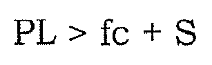
- PL is the distance between the contact tips of adjacent contact probes;
- fc is the diameter of the
contact probes 4; and - S is the safety distance between
adjacent contact probes 4. - Condition S-0, i.e. a safety distance equal to zero, corresponds to the probes colliding.
- It is to be noted that the diameter fc of the
contact probes 4 is usually taken into account, since such probes are normally formed by metal wires with a circular cross section. More generally, the probe's diameter is understood as the maximum dimension of its section perpendicular to a longitudinal extension axis of the same probe, which, according to the previous definitions, is considered as extending along the side by side placing direction of the probes, i.e. where they can contact each other. - According to the current technologies, in order to increase the number of probes, with a same pitch value, it is known to reduce the size of the
contact probes 4, in particular their diameter fc, causing a weakening of the same. Such a solution is therefore applicable in a limited number of cases only. -
US patent application No. 2008/0204062 discloses a cantilever contact probe wherein at least a portion of the hook-shaped tip is flattened by stamping or pressing devices, resulting in a reduced size along a first side by side placing direction of the probes and at the same time in an increased size along a second direction, orthogonal to the first direction, of the flattened portion with respect to the non-flattened portion. - It is also known that, with high
density contact pads 7, thecontact probes 4 are positioned over multiple levels or layers, therefore varying the lengths L1,....Ln of the hook-shapedend portions 4A, as schematically shown inFigure 2B . - The number N of levels required for positioning a plurality of
contact probes 4 having diameter fc overcontact pads 7 having distance or pitch equal P, ensuring a safety distance S between each other, is calculated according to the following empirical formula:
- In case of testing heads having
cantilever contact probes 4 positioned on multiple levels, the problem caused by collision of probes has evidently a three-dimensional character. In particular, the sites with the greatest risk of contact are the bending points PG of a probe at a level corresponding to a slightly tapered area of the hook-shaped end portion 4A ofadjacent contact probes 4. - It is therefore advantageous, if possible, to position the
contact probes 4 on a minimum number of levels. - Essentially, the choice of the positioning arrangement of the
contact probes 4 over multiple levels depends on various factors, among which the most important are the following: - available space for the
contact probes 4 as a whole; - diameter fc of each
contact probe 4; - shape of the hook-shaped
end portions 4A; and - pitch of the device under
test 8. - Considering a fixed pitch value for the device under
test 8, it is possible to increase the number of probes housed on each level by reducing their diameter. - However it is to be noted that the
contact probes 4 having a small diameter have a lower mechanical and electrical performance, due to the increase of the contact resistance between hooks and pads of the device undertest 8, because of the lower pressure which is applied by the tips of thecontact probes 4 on therespective contact pads 7. - It can be easily shown that also the length of the scrub marks is heavily influenced by the hook's length. An increase of the number N of levels, which causes an increase of the hook's length, causes also an increase of the associated scrub marks.
- In particular, in a testing head having
contact probes 4 on N levels, the probe oflevel 11, having a hook length of L1, produces a shorter scrub mark with respect to the probe atlevel 12, having a hook length L2, which in turn is shorter than the one generated by the probe onlevel 13, having a hook length L3. - The probe belonging to the higher level, ln, having a longest hook, Ln, will therefore create a longest scrub mark and will consequently inflict the maximum damage to the
contact pads 7. - The need of placing the probes on multiple levels essentially contrasts the need of limiting or even reducing the length of the scrub marks, i.e. the damage caused to the contact pads and the risk of crossing their borders, even more so because the size of the contact pads is steadily decreasing.
- Moreover, by increasing the levels, the collision risk among the probes on higher levels is also increased, because their minimum mutual distance is also decreased, due to the conical shape of the probes.
- As will become apparent from the above description, there are contrasting needs which require very precarious compromises to be made, and which severely compromise a good functionality of the testing head according to the prior art.
- The technical problem to be solved by the present invention is to provide a cantilever contact probe with an arrangement such as to reduce the probability of a contact even in a device under test having a reduced pitch, to increase the safety distance between probes and to reduce the scrub of the tips over the contact pads, at the same time ensuring a proper mechanical and electrical contact between the probes and the contact pads.
- The solution idea of the present invention is to modify the arrangement of the contact probes in at least a portion of their probe body, reducing the thickness of said body along a side by side placing direction of the probes.
- According to the above solution idea, the technical problem is solved by a cantilever contact probe comprising at least a probe body and a hook-shaped end portion, being joined to the probe body and ending with a slanted section, being configured as a hook, the end portion being bent at a bending point having a suitable inclination of the hooked slanted section with respect to a longitudinal extension axis of the probe and ending with a contact tip being able to ensure a mechanical and electrical contact with a contact pad of a device under test, characterized in that it comprises at least a reduced portion having a first area with at least a first size being smaller than a corresponding first size of a second area of the probe in a section which does not comprise the reduced portion, along a side by side placing direction of the probes within a testing head, the reduced portion being substantially reduced along its sides, thus forming an area having a reduced cross size being placed edgeways.
- According to an aspect of the invention, the ratio between the first size of the first area at the reduced portion and the size of the second area may be chosen in the range 0.30 - 0.95.
- According to another aspect of the invention, the reduced portion may be symmetrical with respect to the longitudinal extension axis of the probe.
- Moreover, according to an aspect of the invention, the first area of the probe at the reduced portion has a second size along the orthogonal direction with respect to the side by side placing direction of the probes which is greater than the first size.
- According to another aspect of the invention, the contact tip may comprise a corrugated contact portion.
- Moreover, the reduced portion may be provided in a section of the probe body adjoining the end portion.
- The reduced portion may also be provided in a section of the end portion at the bending point.
- According to an aspect of the invention, the probe may comprise a reduced portion provided in a section of the probe body adjoining the end portion and a further reduced portion provided in a section of the end portion at the bending point.
- According to another aspect of the invention, the value of the first size of the first area at the reduced portion may be chosen according to a value of a distance between the centers of the contact pads of the device under test.
- Moreover, according to another aspect of the invention, the value of the second size of the first section at the reduced portion may be chosen according to a current that the probe should sustain.
- According to a further aspect of the invention, the values of first and second sizes of the first area at the reduced portion may be chosen to control the contact force of the probe onto a contact pad of the device under test or to balance probes having slanted sections of different length or to contact pads being internal to the device.
- The value of the first size of the first area at the reduced portion may vary between 25 µm and 200 µm and the value of the first size of the second area may vary between 50 µm and 300 µm. Alternatively, the value of the first size of the first area at the reduced portion may vary between 20 µm and 180 µm and the value of the first size of the second area may vary between 30 µm and 200 µm. Moreover, the value of the second size of the first area at the reduced portion may vary between 50 µm and 400 µm.
- According to another aspect of the invention, the first area at the reduced portion may have a shape chosen between a substantially quadrilateral figure which comprises two opposed rectilinear sides and two opposed curvilinear sides, a rectangle, a square, and an ellipse.
- The technical problem is also solved by a testing head comprising at least a ring support, which is jointly coupled to a further resin support being able to include a plurality of cantilever contact probes according to the preceding aspects.
- According to an aspect of the invention, the testing head may comprise at least a first level of contact probes having at least a reduced portion provided in a section of the end portion at the bending point and a second level of contact probes devoid of the reduced portion.
- The characteristics and advantages of the contact probe and f the testing head according to the invention will be provided in the following description of their embodiments, provided as illustrative and non limiting examples, with reference to annexed drawings.
- In the drawings:
-
Figure 1A shows a view from above of a testing head with cantilever probes according to the prior art, -
Figure 1B shows a front sectional view of the testing head with cantilever probes ofFigure 1A , -
Figure 2A shows a sectional view of a detail of the testing head with cantilever probes ofFigure 1A , -
Figure 2B shows a sectional view of a detail of another embodiment of a testing head with cantilever probes according to the prior art, -
Figure 3A shows a perspective view of a cantilever contact probe according to the prior art, -
Figure 3B shows a sectional transversal view of a cantilever contact probe ofFigure 3A , -
Figure 4A shows a perspective view of a cantilever contact probe according to an embodiment of the invention, -
Figures 4B and 4C show sectional views of the cantilever contact probe ofFigure 4A , -
Figure 5A shows a perspective view of a testing head including cantilever contact probes according toFigure 4A , -
Figure 5B shows a view from above of a detail of the testing head ofFigure 5A , comparing known cantilever contact probes according toFigure 3A and cantilever contact probes according to the embodiment of the invention ofFigure 4A , -
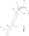
Figure 6 shows a perspective view of a cantilever contact probe according to an alternative embodiment of the invention, -
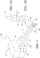
Figure 7 shows a perspective view of a testing head including cantilever contact probes according toFigure 6 , -
Figures 7A and 7B show a front view of a detail of a testing head ofFigure 7 , comparing known cantilever contact probes ofFigure 3A and cantilever contact probes according to the alternative embodiment of the invention ofFigure 6 , respectively, -
Figure 8 shows a perspective view of a cantilever contact probe according to a further alternative embodiment of the invention, and -
Figures 9A-9E show cross sections of cantilever contact probes according to alternative embodiments of the invention. - With particular reference to
Figures 3A and 4A , a cantilever contact probe according to the prior art (Figure 3A ) and a cantilever contact probe according to an embodiment of the invention (Figure 4A ) are schematically shown. - In particular, the
cantilever contact probe 10 according to the prior art, shown inFigure 3A , comprises aprobe body 11 and anend portion 12, joined to theprobe body 11 and ending with a slantedsection 13, in a hook-shaped arrangement. As already said, theend portion 12 is bent at abending point 14 with a suitable inclination of the slantedsection 13 with respect to the axis of theprobe body 11, and it ends with acontact tip 15, for contacting a plurality ofcontact pads 7 of a device under test. - The
probe body 11 has a rod-like shape, having a substantially constant sectional area with a circular shape of diameter D, as schematically shown inFigure 3B , which shows a cross section of saidprobe body 11 at a transversal plane α as shown inFigure 3A . - Usually, for a probe having a total length between 3,8 and 8 cm, the length of the
probe body 11 varies between 3,7 cm and 7,7 cm and the length of the hook-shapedend portion 12 varies between 1 mm and 3 mm, wherein the length of the slantedsection 13 may vary between 0,15 mm and 1,5 mm. Furthermore, the diameter D ofprobe body 11 may vary between 50 µm and 300 µm, whereas the diameter d ofcontact tip 15, which is also substantially circular, may vary between 8 µm and 80 µm. In this way, the hook-shapedend portion 12 has a tapered frustoconical shape. - A cantilever contact probe according to the invention shown in
Figure 4A , generally indicated in 20, comprises aprobe body 21 and anend portion 22, joined to theprobe body 21 and ending with a slanted hook-shapedsection 23. Theend portion 22 is bent at abending point 24 with a suitable inclination of the slanted hook-shapedsection 23, with respect to a longitudinal extension axis of theprobe body 21, and ending with acontact tip 25, for contacting a plurality ofcontact pads 7 of a device under test. - Advantageously, according to the invention, the
cantilever contact probe 20 comprises at least a reducedportion 26 having an area with at least a first size smaller than a corresponding first size of the area of the rest of the probe, in particular along the side by side placing direction of the probes inside a testing head, labeled as Dir inFigure 4A . More in particular, such reduced portion is reduced on the sides, forming an area of reduced cross size positioned edgeways, wherein such probes are positioned, as will be made clear in the following, in such a way as to protrude from a supporting ring on at least one level, intended to be the height of the point where the probes protrude from the supporting ring, or more precisely from the resin support associated to the same, with respect to a device under test, in a side by side arrangement of same probes. The probes on a given level may be considered as placed side by side along a plane, which we call probe plane, at a certain distance from a defined plane of the device under test, when the testing head comprising such probes is in contact and pressing on the same, wherein each level corresponds to a different distance between the probe plane and the plane of the device under test. - In the embodiment of
Figure 4A , thecantilever contact probe 20 has a reducedportion 26, which is in particular provided in a section of theprobe body 21 adjoining theend portion 22, having a first area A1 shown inFigure 4B , taken in correspondence of a first transversal plane β ofFigure 4A with a first size B, in particular, a maximum size in the side by side direction of the probes Dir, and a second size H, in particular, a maximum size in a direction perpendicular to the side by side direction of the probes Dir. In essence, the first size B is the thickness of the reducedportion 26 of thecantilever contact probe 20 and the second size H is its height. In a preferred embodiment, the second size H is greater than the first size B. - The
cantilever contact probe 20 also has a second area A2 shown inFigure 4C , taken in correspondence of a second transversal plane γ inFigure 4A , therefore corresponding to theprobe body 21, where the reducedportion 26 is absent, the area A2 being circular with a diameter B', which in the example shown is equal to the area A of thecantilever contact probe 10 ofFigure 3A . - The reduced
portion 26 may be provided by suitable working of thecantilever contact probe 20, for example by removing material in a symmetrical fashion with respect to the longitudinal extension axis of thecantilever contact probe 20, from a section of theprobe body 21, providing a sort of symmetrical recess in that section. - Advantageously, according to the invention, the first size B of the first area A1, taken in correspondence of the reduced
portion 26, is smaller than the first size B' of the second area A2, taken in correspondence of the section of theprobe body 21 lacking the reducedportion 26, along the same side by side direction of the probes Dir, and transversally with respect to theprobe body 21. In a preferred embodiment, the second area A2 has a circular shape with a diameter B', and the second size H of the first area A1 is equal to said diameter B'. - In a further preferred embodiment, the first size B of the first area A1 of the reduced
portion 26 is equal to even 20% of the first size B' of the second area A2 along the same side by side placing direction of the probes Dir. In general, the ratio between the first size B of the first area A1 and the first size B' of the second area is chosen between 0.30 and 0.95. - The hook-shaped
end portion 22 of eachcantilever contact probe 20 ends with acontact tip 25, wherein such tip is such as to abut against and contact a plurality of contact pads of a device under test. - It has to be noted that the provision of the reduced
portion 26 in theprobe body 21 alters the elastic properties of thecantilever contact probe 20 as a whole, and in particular of theprobe body 21, and allows a reduction of the number of levels at which the probes have to be positioned. - For a probe with a total length varying between 3.8 cm and 8 cm, the length of the
probe body 21 varies between 3.7 cm and 7.7 cm, and the length of the hook-shapedend portion 22 varies between 1 mm and 3 mm and the length of the slantedsection 23 may vary between 0.15 mm and 1.5 mm. Furthermore, the first size B' or diameter of theprobe body 21 in circular probes may vary between 50 µm and 300 µm, whereas the diameter d of thecontact tip 25, which is also essentially circular in shape, may vary between 8 µm and 80 µm. - In an exemplary embodiment, the value of the first size B of the reduced
portion 26 varies between 25 µm and 200 µm and the value of the second size H of the reducedportion 26 varies between 50 µm and 400 µm, whereas the first size B' of the section of theprobe body 21 not comprising the reducedportion 26 may vary between 50 µm and 300 µm. - Advantageously, according to the invention, the
contact tip 25 may also have a contact portion, which is suitably corrugated, in order to abut against a covering layer or film (oxide or dirt in general) overlaying the contact pad of the device under test. - Advantageously, in this way, according to the invention, the
contact tip 25 "sticks" at the impact area on the contact pad, limiting the scrubbing action by the same tip, wherein theprobe 20 presses in contact against the contact pad, which has traveled vertically, by a distance called overtravel OT. - The hook-shaped
end portion 22 of thecantilever contact probe 20 according to the invention therefore deforms during such pressing contact against the contact pad, wherein its horizontal movement or scrub against the same pad is limited by the corrugated contact portion being stuck on the covering layer of the contact pads. - It is also to be noted that such sticking action is eased by the reduced
portion 26 provided in theprobe body 21, which improves the flexibility of the probe. By using cantilever contact probes 20 according to the invention, scrub marks are therefore reduced with respect to the probes according to the prior art. - A testing head according to an embodiment of the invention is schematically and partially shown in
Figure 5A , globally labeled as 30. In particular, thetesting head 30 comprises aring support 27 made of aluminum, ceramics or other suitable material to which afurther resin support 28 is jointly coupled, able to include a plurality of cantilever contact probes 20, in order for the same to be essentially aligned on a same level, considered as the level or height at which the cantilever contact probes 20 exit from thefurther resin support 28 with respect to a ideal plane formed by the device under test, when thetesting head 30 is pressing in contact against the same. - In the embodiment shown in
Figure 5A , the cantilever contact probes 20 are included in thefurther resin support 28 at their corresponding reducedportions 26, which are provided, as in the example shown inFigure 4A , on theprobe body 21. - It is therefore clear that in the
testing head 30, the cantilever contact probes 20 may be more narrowly spaced in thefurther resin support 28, with respect to cantilever contact probes 10 made according to prior art, due to the reduced size precisely in the side by side direction of the probes Dir, in particular the first size B of the first area A1 at the reducedportion 26. - A
testing head 30 can therefore be provided which is able to test devices having a reduced pitch with respect to those that may be tested by a traditional testing head of the prior art. - In order to completely appreciate the advantageous characteristics of the
testing head 30 comprising cantilever contact probes 20 according to the invention, one may refer toFigure 5B , where, in the left portion, a pair of cantilever contact probes 10 made according to the prior art is shown, which are placed side by side and contiguous to each other along the direction Dir, having a substantially circular cross section, whereas the portion on the right shows a pair of cantilever contact probes 20 made according to the invention, which are similarly placed side by side and contiguous to each other, at their reducedportions 26. - It is readily understood that distance P1 between the
contact tips 15 of cantilever contact probes 10 according to prior art is greater than distance P2 between thecontact tips 25 of the cantilever contact probes 20 according to the invention, having both the same safety distance S between probes. In this way, the cantilever contact probes 20 are able to contact pads, whose distance between centers, or pitch, is less than the pitch of the cantilever contact probes 10 of the known type (P2 < P1). - It is also possible to ascertain that the
testing head 30 according to the invention allows the testing of devices having contact pads of extremely reduced size. - In fact, it is to be noted that the reduction of the first size B of the first area A1 of the reduced
portion 26 of theprobe body 21 allows an improvement of the elastic behavior of thecantilever contact probe 20 according to the invention, with reference to its deformation during testing, i.e. during the pressing contact of thecontact tip 25 of thecantilever contact probe 20 against a contact pad of the device under test. - Advantageously, according to the invention, due to its corrugated contact portion, the
contact tip 25 of thecantilever contact probe 20 in any case removes the covering film from the contact pad, on which it is stuck, ensuring a proper electrical contact of theprobe 20 and hence a proper functioning of thetesting head 30 comprising the same. The provision of the corrugated portion of thecontact tip 25 also allows a reduction of the sliding movement of thecontact tip 25 over the contact pad and therefore, as already said, the length of the scrub marks. - Summarizing, it is evident that, in the case of
probe bodies 21 having the same size, the testing head according to the invention allows testing of devices having reduced pitch and small pads, ensuring high quality and reliability. New requirements imposed by new technologies, with reference to the more and more reduced sizes of the contact pads and pitch, are therefore met. - Since, due to the reduction of the scrub marks, the size of contact pads may be reduced, the
testing head 30 also allows a great area saving for each device, and a greater number of devices fits on the same silicon area. - Finally, due to the configuration of the cantilever contact probes 20, a
testing head 30 may be provided which has a lower number of levels with respect to those used in the prior art for testing the same device, wherein each level of cantilever contact probes 20 may contact a higher number of contact pads, thanks to the reduced distance between therespective contact tips 25. - According to an alternative embodiment, a
cantilever contact probe 20' comprises a reduced portion 26' at itsend portion 22, as schematically shown inFigure 6 . In particular, the reduced portion 26' is provided at thebending point 24 of theend portion 22, in a substantially symmetrical arrangement with respect tosuch bending point 24. - As previously shown, the reduced portion 26' may be manufactured by suitable working of the
cantilever contact probe 20, for example by means of symmetrical material removal with respect to the longitudinal extension axis of thecantilever contact probe 20', from a section of theend portion 22, for example a section symmetrically positioned on thebending point 24, in order to provide a sort of symmetrical recess in said section. - Similarly to the embodiment of
Figure 5A , the reduced portion 26' has a first area being similar to the area A1 as shown inFigure 4B , taken in correspondence of thebending point 24 with a first size B, in particular, a maximum size in the side by side direction of the probes Dir, and a second size H, in particular, a maximum size in a direction perpendicular to the side by side direction of the probes Dir. - The
cantilever contact probe 20' also has a second area A2 as the one shown inFigure 4C , taken in correspondence of aend portion 22, where the reduced portion 26' is absent, having a first size B' in the side by side direction of the probes Dir being greater that the first size A1 taken in correspondence of the reduced portion 26'; in particular, the area A2 may have a circular shape with a diameter equal to the first size B'. - Advantageously, according to the invention, the first size B of the first area A1, taken in correspondence of the reduced
portion 26, is smaller than the first size B' of the second area A2, taken in correspondence of the section of theprobe body 21 lacking the reducedportion 26, along the same side by side direction of the probes Dir, and transversally with respect to theprobe body 21. In a preferred embodiment, the second area A2 has a circular shape with a diameter B', and the second size H of the first area A1 is equal to said diameter B'. - Similarly to the preceding embodiment, the first size B of the first area A1 of the reduced portion 26' is up to 20% of the first size B' of the second area A2 along the same side by side direction of the probes Dir. In general, the ratio between the first size B and second size H is chosen between 0.30 and 0.95.
- The hook-shaped
end portion 22 of eachcantilever contact probe 20, in particular its slantedsection 23, ends with acontact tip 25, whose diameter is essentially equal to the known probes' one, wherein said tip is such as to abut and contact against a plurality of contact pads of the device under test. - Also according to this second embodiment, the provision of the reduced portion 26' in the
end portion 22 improves the elastic properties ofsuch end portion 22 and of thecantilever contact probe 20 as a whole, also allowing a reduction of the length of the slantedsections 23. - In the probe according to this alternative embodiment, in particular with reference to its length and the length of its individual portions, dimensional values equal to those of the probe as previously described and shown in
Figure 4A are presumed. - In an exemplary embodiment, the value of the first size B of the reduced portion 26' varies between 20 µm and 180 µm and the value of the second size H of the reduced portion 26' varies between 50 µm and 400 µm, whereas the first size B' of the section of the
end portion 22 not comprising the reduced portion 26' may vary between 30 µm and 200 µm. - The
contact tip 25 may also comprise a contact portion suitably corrugated, such as to abut against a covering layer or film (oxide or dirt in general), overlaying the contact pad of the device under test, so that thecontact tip 25 is able to "stick" at the impact zone on the contact pad, limiting the scrub and, as previously indicated, forming smaller scrub marks. - In this case, too, the sticking action is facilitated by the provision of the reduced portion 26' in the hook-shaped
end portion 22, with an improved elastic behavior during testing. - Such alternative embodiment is particularly advantageous in case of positioning the cantilever contact probes on multiple levels, as schematically shown in
Figures 7, 7A and 7B . - In particular,
Figure 7 schematically shows a testing head 30' comprising cantilever contact probes on at least two levels, 11 and 12. - As previously shown, the testing head 30' comprises a
ring support 27, made of aluminum, ceramics or other suitable material, to which afurther resin support 28 is solidly joined, such as to include a first plurality of cantilever contact probes 20 aligned on afirst level 11, as well as a second plurality of cantilever contact probes aligned on asecond level 12, in particular a higher level, i.e. at a greater distance from the device under test. - It is pointed out that, advantageously, according to the invention, the cantilever contact probes at the
second level 12 may be provided using cantilever contact probes without reduced portions, as those indicated by 10 inFigure 3A . In particular, theend portions 12 of the cantilever contact probes 10 at the second level are such as to be housed without risking any contacting between theend portions 22 of the cantilever contact probes 20' of thefirst level 11, due to provision of the reduced portions 26' being realized at corresponding bending points 24 of the cantilever contact probes 20' of the first level, indeed, with a substantial reduction of the distances betweenrespective contact tips 25. - More in particular, based on comparison of
Figures 7A and 7B , it is possible to confirm that the two level configuration of the testing head 30' comprising afirst level 11 of cantilever contact probes 20' according to embodiment inFigure 6 and asecond level 12 of cantilever contact probes 10 of the known type (shown inFigure 7B ), is able to position therespective contact tips 25 closer with respect to the testing head only comprising known cantilever contact probes 10 (shown inFigure 7A ), with a reduction of total distance between the contact tips of the probes at thefirst level 11 equal to R. - It is therefore evident that also the testing head 30' comprising at least one
level 11 of cantilever contact probes 20' according to the embodiment ofFigure 6 is such as to allow the testing of devices with smaller pitch with respect to a traditional testing head only comprising cantilever contact probes 10 ofFigure 3A . - Advantageously, according to a further alternative embodiment schematically shown in
Figure 8 , acantilever contact probe 20" may comprise a first reducedportion 26 in a section of theprobe body 21 which is contiguous to theend portion 22 and a second reduced portion 26' at anend portion 22, in particular, at abending point 24 of theend portion 22, in a substantially symmetrical arrangement with respect to thebending point 24. - In the probe according to this further embodiment, in particular, with reference to its length and the length of the individual portions and the sizes of different areas are presumed to have dimensional values equal to those of the probes, previously described and shown in
Figures 4A and6 . - A testing head comprising cantilever contact probes 20" according to further embodiment of
Figure 8 clearly allow a further reduction of the distance of therespective contact tips 25, for testing devices having extremely small pitches. - In this case too, the
contact tip 25 of the cantilever contact probes 20" may have a suitably corrugated contact portion able to abut against a covering layer or film (oxide or dirt in general) overlaying the contact pad of the device under test, such as to allow testing of devices having contact pads of extremely small size. - Possible areas of the reduced section of the contact probes according to the present invention are shown, as non limiting examples, in
Figures 9A to 9F . - As is shown in these figures, the areas of the reduced portions of the cantilever contact probes according to the present invention may be substantially rectangular, with variable base and height, or even substantially elliptical, with variable major and minor axes.
- The choice of the sections of the reduced portions may be based on different criteria:
- starting with a defined pitch, required by the device under test, it is possible to establish a value of the first size B, sufficient to ensure a lack of contact between adjacent and contiguous probes;
- based on the current capacity required by a defined test, it is possible to establish a value of the second size H, also based on the value already determined for the first size B.
- In particular, as shown in
Figure 9A , a cantilever contact probe, for example aprobe 20 as shown inFigure 4A , may have a first size B1 of its first area A1 at its reducedportion 26, sufficient to contact a device having a first pitch P1. - In case of testing a device having a second pitch P2 smaller than the first pitch P1, it is possible to use a
cantilever contact probe 20 with a reducedportion 26 with a first further reduced size B2 of its area A1, as shown inFigure 9B , being B1 > B2 and H1 = H2. - Furthermore, if the value of the first size B3 of the section of the
cantilever contact probe 20 at its reducedportion 26 is sufficient to ensure the proper pitch required by the device under test, it may be necessary to perform a test with a higher current requirement. In this case, acantilever contact probe 20 having a higher current capacity may be provided, increasing the second size H3, as shown inFigure 9C , being B3 = B2 and H3 > H2. - The areas shown in
Figures 9A-9C have two opposed rectilinear sides and two opposed curvilinear sides. It is also possible to use cantilever contact probes 20 having reducedportions 26 with a rectangular cross section, as shown inFigure 9D or elliptical cross section, as shown inFigure 9E , being B4 = B5 and H4 = H5. Moreover, the reducedportion 26 may also have a square section, with a side shorter than the diameter of theprobe body portion 21, respectively of theend portion 22, not comprising the reducedportion 26, respectively 26'. - Similar considerations may also be made for the
probes Figures 6 and8 , respectively, and for the respective reducedportions 26, 26'. - Other and different embodiments of the reduced
portions 26 of thecantilever contact probe 20 may also be taken into account. - It is also noted that the value of the sizes B and H of the reduced
portion 26 of the cantilever contact probes 20 may also be modified for controlling the contact force or for increasing their balancing in case probes with hooks of different length have to be used, or if it is necessary to contact pads inside the device, as is the case of last generations of integrated devices comprising contact pads which are provided also inside the device, in addition to its periphery. - Summarizing, the testing head comprising cantilever contact probes according to the different embodiments as shown allows:
- a reduction of the number of levels at which the probes are positioned, with a corresponding balancing of forces and improved uniformity of the scrub action over the contact pads;
- an increase of the length of the hooks of the contact probes positioned on a reduced number of levels, therefore increasing the working life of the testing head, which is tied to the wear of the hooks, indeed;
- an increase of probe's diameter, without the risk of mutual collision between the same, therefore improving the current capacity of the probes;
- a reduction of the length of the scrub marks, at a same overtravel;
- a reduction of the usable pitch value;
- a reduction of the size of the contactable contact pads;
- an increase of the distance between the probes, therefore obtaining an easier and more reliable manufacturing of the testing head as a whole.
- More in particular, the provision of the reduced
portion 26 allows different and important advantages, among which are the following: - improving the balance of forces, which may be regulated by varying the first size of the reduced
portion 26, 26', in particular, the depth of the groove on theprobe body 21, as a function of the length of the slanted hook-shapedsection 23, which characterizes various levels of probes; - improving the balance of forces, when the device under test has various internal pads,
- improving the uniformity of the scrubs obtained on the pads by controlling the respective scrub's length up to almost eliminating the same (when the scrub mark is slightly larger than the size of the contact tip of the probe, the removal of the dirt layer on the pad and therefore a proper electrical connection being obtained due to sticking of the contact tip on the same pad).
- possible increase of the current capacity of the probe, due to a suitable increase of the second size H of the
probe body 21 in a transversal direction with respect to the side by side placing direction of the probes Dir.
Claims (13)
- Cantilever contact probe (20, 20', 20") comprising at least a probe body (21) and a hook-shaped end portion (22), being joined to said probe body (21) and ending with a slanted section (23) being configured as a hook, said end portion (22) being bent at a bending point (24) having a suitable inclination of said hooked slanted section (23) with respect to a longitudinal extension axis of said probe (20, 20', 20") and ending with a contact tip (25) being able to assure a mechanical and electrical contact with a contact pad of a device under test, characterized in that it comprises at least a reduced portion (26, 26') having a first area (A1) with at least a first size (B) being smaller than a corresponding first size (B') of a second area (A2) of said probe in a section which does not comprise said reduced portion (26, 26'), along a side by side placing direction of the probes (Dir) within a testing head, said reduced portion (26, 26') being substantially reduced along its sides thus forming an area having a reduced cross size being placed edgeways, said first area (A1) having a second size (H) along the orthogonal direction with respect to said side by side placing direction of the probes (Dir) being equal to a size of said second area (A2) along a same orthogonal direction, equal to said first size (B').
- Cantilever contact probe (20, 20', 20") according to claim 1, characterized in that the ratio between said first size (B) of said first area (A1) at said reduced portion (26, 26') and said first size (B') of said second area (A2) is chosen in the range 0.30-0.95.
- Cantilever contact probe (20, 20', 20") according to any of the preceding claims, characterized in that said reduced portion (26) is symmetrical with respect to said longitudinal extension axis of said probe (20, 20', 20").
- Cantilever contact probe (20, 20', 20") according to any of the preceding claims, characterized in that said contact tip (25) comprises a corrugated contact portion.
- Cantilever contact probe (20, 20") according to any of the preceding claims, characterized in that said reduced portion (26) is made in a section of said probe body (21) adjoining said end portion (22).
- Cantilever contact probe (20') according to any of claims 1-4, characterized in that said reduced portion (26') is made in a section of said end portion (22) at said bending point (24).
- Cantilever contact probe (20") according to claim 5, characterized in that it comprises said reduced portion (26) being made in a section of said probe body (21) adjoining said end portion (22) and a further reduced portion (26') being made in a section of said end portion (22) at said bending point (24).
- Cantilever contact probe (20, 20', 20") according to any of the preceding claims, characterized in that the value of said first size (B) of said first area (A1) at said reduced portion (26, 26') is chosen according to a value of a distance between the centers of the contact pads of said device under test.
- Cantilever contact probe (20, 20', 20") according to any of the preceding claims, characterized in that the value of said second size (H) of said first area (A1) at said reduced portion (26, 26') is chosen according to a value of a current that the probe should sustain.
- Cantilever contact probe (20, 20', 20") according to any of the preceding claims, characterized in that the values of said first and second sizes (B, H) of said first area (A1) at said reduced portion (26, 26') are chosen to control the contact force of said probe (20, 20', 20") onto a contact pad of said device under test or to balance probes having slanted sections (23) of different length or to contact pads being internal to said device.
- Cantilever contact probe (20, 20', 20") according to any of the preceding claims, characterized in that said first area (A1) in correspondence with said reduced portion (26, 26') has a shape being chosen between a substantially quadrilateral figure which comprises two opposed rectilinear sides and two opposed curvilinear sides, a rectangle, a square, an ellipse.
- Testing head (30) comprising at least a ring support (27) which is jointly coupled to a further resin support (28) being able to include a plurality of cantilever contact probes (20, 20', 20") being realized according to any of the preceding claims.
- Testing head (30) according to claim 12, characterized in that it comprises at least a first level (11) of contact probes (20', 20") having at least a reduced portion (26') which is realized in a section of said end portion (22) at said bending point (24) and a second level (12) of contact probes being devoid of said reduced portion.
Applications Claiming Priority (2)
| Application Number | Priority Date | Filing Date | Title |
|---|---|---|---|
| IT002023A ITMI20122023A1 (en) | 2012-11-28 | 2012-11-28 | SHIELD CONTACT PROBE [CANTILEVER] FOR A MEASURING HEAD |
| PCT/EP2013/003587 WO2014082742A1 (en) | 2012-11-28 | 2013-11-27 | Cantilever contact probe for a testing head |
Publications (2)
| Publication Number | Publication Date |
|---|---|
| EP2926150A1 EP2926150A1 (en) | 2015-10-07 |
| EP2926150B1 true EP2926150B1 (en) | 2017-01-04 |
Family
ID=47633160
Family Applications (1)
| Application Number | Title | Priority Date | Filing Date |
|---|---|---|---|
| EP13814035.5A Not-in-force EP2926150B1 (en) | 2012-11-28 | 2013-11-27 | Cantilever contact probe for a testing head |
Country Status (8)
| Country | Link |
|---|---|
| US (1) | US20150192614A1 (en) |
| EP (1) | EP2926150B1 (en) |
| JP (1) | JP2015537213A (en) |
| KR (1) | KR20150090017A (en) |
| IT (1) | ITMI20122023A1 (en) |
| SG (1) | SG11201407070PA (en) |
| TW (1) | TWI595239B (en) |
| WO (1) | WO2014082742A1 (en) |
Families Citing this family (8)
| Publication number | Priority date | Publication date | Assignee | Title |
|---|---|---|---|---|
| JP6407672B2 (en) * | 2014-11-18 | 2018-10-17 | ルネサスエレクトロニクス株式会社 | Manufacturing method of semiconductor device |
| TWI626452B (en) * | 2017-01-09 | 2018-06-11 | Probe head architecture for vertical probes and their probe cards | |
| IT201800001170A1 (en) * | 2018-01-17 | 2019-07-17 | Technoprobe Spa | Cantilever-type measuring head and relative contact probe |
| EP3740767A1 (en) * | 2018-01-18 | 2020-11-25 | Xcerra Corp. | Capacitive test needle for measuring electrically conductive layers in printed circuit board holes |
| TWI704355B (en) * | 2019-07-22 | 2020-09-11 | 旺矽科技股份有限公司 | Suitable for probe modules with multiple units to be tested with inclined conductive contacts |
| CN111089990A (en) * | 2019-12-25 | 2020-05-01 | 奥士康科技股份有限公司 | Three-head test needle |
| CN116359569A (en) * | 2021-12-27 | 2023-06-30 | 财团法人工业技术研究院 | Probe card |
| CN117686753A (en) * | 2023-12-20 | 2024-03-12 | 西安交通大学 | A micro-coaxial radio frequency cantilever probe structure and application |
Family Cites Families (11)
| Publication number | Priority date | Publication date | Assignee | Title |
|---|---|---|---|---|
| US3599093A (en) * | 1969-04-28 | 1971-08-10 | Rca Corp | Apparatus including a wire tipped probe for testing semiconductor wafers |
| JPH04360549A (en) * | 1991-06-07 | 1992-12-14 | Nippon Denshi Zairyo Kk | High density probe card |
| JPH1138041A (en) * | 1997-07-24 | 1999-02-12 | Mitsubishi Electric Corp | Cantilever type probe needle for probe card, its manufacturing method and control method |
| US6143668A (en) * | 1997-09-30 | 2000-11-07 | Intel Corporation | KLXX technology with integrated passivation process, probe geometry and probing process |
| ITMI20012574A1 (en) * | 2001-12-06 | 2003-06-06 | Technoprobe S R L | CONTACT PROBE FOR A MEASUREMENT HEAD |
| JP4088121B2 (en) * | 2002-08-14 | 2008-05-21 | 富士通株式会社 | Contactor manufacturing method |
| TW200725015A (en) * | 2005-12-21 | 2007-07-01 | Chao-Chih Lai | LCD panel defect inspection system |
| JP2007218840A (en) * | 2006-02-20 | 2007-08-30 | Fujitsu Ltd | Probe, probe card and inspection device |
| US7679383B2 (en) * | 2007-02-28 | 2010-03-16 | Sv Probe Pte. Ltd. | Cantilever probe card |
| JP5069542B2 (en) * | 2007-12-03 | 2012-11-07 | 株式会社日本マイクロニクス | Probe card |
| JP2010164452A (en) * | 2009-01-16 | 2010-07-29 | Micronics Japan Co Ltd | Probe and probe card |
-
2012
- 2012-11-28 IT IT002023A patent/ITMI20122023A1/en unknown
-
2013
- 2013-11-27 KR KR1020157001300A patent/KR20150090017A/en not_active Withdrawn
- 2013-11-27 WO PCT/EP2013/003587 patent/WO2014082742A1/en not_active Ceased
- 2013-11-27 EP EP13814035.5A patent/EP2926150B1/en not_active Not-in-force
- 2013-11-27 JP JP2015543346A patent/JP2015537213A/en active Pending
- 2013-11-27 SG SG11201407070PA patent/SG11201407070PA/en unknown
- 2013-11-28 TW TW102143411A patent/TWI595239B/en not_active IP Right Cessation
-
2015
- 2015-03-04 US US14/638,533 patent/US20150192614A1/en not_active Abandoned
Also Published As
| Publication number | Publication date |
|---|---|
| JP2015537213A (en) | 2015-12-24 |
| ITMI20122023A1 (en) | 2014-05-29 |
| WO2014082742A1 (en) | 2014-06-05 |
| SG11201407070PA (en) | 2014-11-27 |
| TWI595239B (en) | 2017-08-11 |
| EP2926150A1 (en) | 2015-10-07 |
| TW201432267A (en) | 2014-08-16 |
| US20150192614A1 (en) | 2015-07-09 |
| KR20150090017A (en) | 2015-08-05 |
Similar Documents
| Publication | Publication Date | Title |
|---|---|---|
| US20150192614A1 (en) | Cantilever contact probe for a testing head | |
| KR102133484B1 (en) | Corresponding test head with vertical contact probe and vertical contact probe, especially for high frequency applications | |
| US8415963B2 (en) | Low profile probe having improved mechanical scrub and reduced contact inductance | |
| US9097740B2 (en) | Layered probes with core | |
| US6515496B2 (en) | Microstructure testing head | |
| TWI401439B (en) | Probe head structure for probe test cards | |
| KR102478534B1 (en) | Contact probes and corresponding test heads of devices for testing electronic devices | |
| US20070152686A1 (en) | Knee probe having increased scrub motion | |
| TWI677687B (en) | Electrical connection device | |
| EP2060921A1 (en) | Contact probe for testing head having vertical probes and related testing head for testing microstructure electric performance | |
| EP2110673A1 (en) | Testing head having vertical probes provided with stopping means to avoid their upward and downward escape from respective guide holes | |
| JP5011661B2 (en) | Test method for semiconductor devices | |
| CN121633570A (en) | Probe unit, probe head, probe card and probe system | |
| ITMI20100724A1 (en) | METHOD FOR THE CLEANING OF A CONTACT PITCH OF A MICROSTRUCTURE AND RELATED SHUTTER CONTACT PROBE AND HEAD OF MEASURING PROBES [CANTILEVER]. | |
| KR100430621B1 (en) | Probe of apparatus for testing semiconductor | |
| EP2088443A1 (en) | Contact probe for a testing head having vertical probes with improved scrub movement | |
| JP2011174946A (en) | Testing method of semiconductor element | |
| KR102870178B1 (en) | Probe Card | |
| EP1318409A1 (en) | "Contact probe for a testing head." | |
| JP6373011B2 (en) | Probe card | |
| JP5832371B2 (en) | Contact probe | |
| CN220961635U (en) | Contact probe for IC test | |
| KR100851088B1 (en) | Contact probe on test head | |
| JP6770798B2 (en) | Contact probe | |
| JP2007192719A (en) | Probe card |
Legal Events
| Date | Code | Title | Description |
|---|---|---|---|
| PUAI | Public reference made under article 153(3) epc to a published international application that has entered the european phase |
Free format text: ORIGINAL CODE: 0009012 |
|
| 17P | Request for examination filed |
Effective date: 20141030 |
|
| AK | Designated contracting states |
Kind code of ref document: A1 Designated state(s): AL AT BE BG CH CY CZ DE DK EE ES FI FR GB GR HR HU IE IS IT LI LT LU LV MC MK MT NL NO PL PT RO RS SE SI SK SM TR |
|
| AX | Request for extension of the european patent |
Extension state: BA ME |
|
| DAX | Request for extension of the european patent (deleted) | ||
| REG | Reference to a national code |
Ref country code: DE Ref legal event code: R079 Ref document number: 602013016310 Country of ref document: DE Free format text: PREVIOUS MAIN CLASS: G01R0001073000 Ipc: G01R0001040000 |
|
| RIC1 | Information provided on ipc code assigned before grant |
Ipc: G01R 1/04 20060101AFI20160608BHEP Ipc: G01R 1/067 20060101ALI20160608BHEP Ipc: G01R 1/073 20060101ALI20160608BHEP |
|
| GRAP | Despatch of communication of intention to grant a patent |
Free format text: ORIGINAL CODE: EPIDOSNIGR1 |
|
| INTG | Intention to grant announced |
Effective date: 20160805 |
|
| GRAS | Grant fee paid |
Free format text: ORIGINAL CODE: EPIDOSNIGR3 |
|
| GRAA | (expected) grant |
Free format text: ORIGINAL CODE: 0009210 |
|
| AK | Designated contracting states |
Kind code of ref document: B1 Designated state(s): AL AT BE BG CH CY CZ DE DK EE ES FI FR GB GR HR HU IE IS IT LI LT LU LV MC MK MT NL NO PL PT RO RS SE SI SK SM TR |
|
| REG | Reference to a national code |
Ref country code: GB Ref legal event code: FG4D |
|
| REG | Reference to a national code |
Ref country code: CH Ref legal event code: EP |
|
| REG | Reference to a national code |
Ref country code: AT Ref legal event code: REF Ref document number: 859756 Country of ref document: AT Kind code of ref document: T Effective date: 20170115 |
|
| REG | Reference to a national code |
Ref country code: IE Ref legal event code: FG4D |
|
| REG | Reference to a national code |
Ref country code: DE Ref legal event code: R096 Ref document number: 602013016310 Country of ref document: DE |
|
| REG | Reference to a national code |
Ref country code: LT Ref legal event code: MG4D Ref country code: NL Ref legal event code: MP Effective date: 20170104 |
|
| REG | Reference to a national code |
Ref country code: AT Ref legal event code: MK05 Ref document number: 859756 Country of ref document: AT Kind code of ref document: T Effective date: 20170104 |
|
| PG25 | Lapsed in a contracting state [announced via postgrant information from national office to epo] |
Ref country code: NL Free format text: LAPSE BECAUSE OF FAILURE TO SUBMIT A TRANSLATION OF THE DESCRIPTION OR TO PAY THE FEE WITHIN THE PRESCRIBED TIME-LIMIT Effective date: 20170104 |
|
| PG25 | Lapsed in a contracting state [announced via postgrant information from national office to epo] |
Ref country code: LT Free format text: LAPSE BECAUSE OF FAILURE TO SUBMIT A TRANSLATION OF THE DESCRIPTION OR TO PAY THE FEE WITHIN THE PRESCRIBED TIME-LIMIT Effective date: 20170104 Ref country code: GR Free format text: LAPSE BECAUSE OF FAILURE TO SUBMIT A TRANSLATION OF THE DESCRIPTION OR TO PAY THE FEE WITHIN THE PRESCRIBED TIME-LIMIT Effective date: 20170405 Ref country code: NO Free format text: LAPSE BECAUSE OF FAILURE TO SUBMIT A TRANSLATION OF THE DESCRIPTION OR TO PAY THE FEE WITHIN THE PRESCRIBED TIME-LIMIT Effective date: 20170404 Ref country code: IS Free format text: LAPSE BECAUSE OF FAILURE TO SUBMIT A TRANSLATION OF THE DESCRIPTION OR TO PAY THE FEE WITHIN THE PRESCRIBED TIME-LIMIT Effective date: 20170504 Ref country code: HR Free format text: LAPSE BECAUSE OF FAILURE TO SUBMIT A TRANSLATION OF THE DESCRIPTION OR TO PAY THE FEE WITHIN THE PRESCRIBED TIME-LIMIT Effective date: 20170104 Ref country code: FI Free format text: LAPSE BECAUSE OF FAILURE TO SUBMIT A TRANSLATION OF THE DESCRIPTION OR TO PAY THE FEE WITHIN THE PRESCRIBED TIME-LIMIT Effective date: 20170104 |
|
| PG25 | Lapsed in a contracting state [announced via postgrant information from national office to epo] |
Ref country code: LV Free format text: LAPSE BECAUSE OF FAILURE TO SUBMIT A TRANSLATION OF THE DESCRIPTION OR TO PAY THE FEE WITHIN THE PRESCRIBED TIME-LIMIT Effective date: 20170104 Ref country code: RS Free format text: LAPSE BECAUSE OF FAILURE TO SUBMIT A TRANSLATION OF THE DESCRIPTION OR TO PAY THE FEE WITHIN THE PRESCRIBED TIME-LIMIT Effective date: 20170104 Ref country code: AT Free format text: LAPSE BECAUSE OF FAILURE TO SUBMIT A TRANSLATION OF THE DESCRIPTION OR TO PAY THE FEE WITHIN THE PRESCRIBED TIME-LIMIT Effective date: 20170104 Ref country code: PT Free format text: LAPSE BECAUSE OF FAILURE TO SUBMIT A TRANSLATION OF THE DESCRIPTION OR TO PAY THE FEE WITHIN THE PRESCRIBED TIME-LIMIT Effective date: 20170504 Ref country code: SE Free format text: LAPSE BECAUSE OF FAILURE TO SUBMIT A TRANSLATION OF THE DESCRIPTION OR TO PAY THE FEE WITHIN THE PRESCRIBED TIME-LIMIT Effective date: 20170104 Ref country code: ES Free format text: LAPSE BECAUSE OF FAILURE TO SUBMIT A TRANSLATION OF THE DESCRIPTION OR TO PAY THE FEE WITHIN THE PRESCRIBED TIME-LIMIT Effective date: 20170104 Ref country code: PL Free format text: LAPSE BECAUSE OF FAILURE TO SUBMIT A TRANSLATION OF THE DESCRIPTION OR TO PAY THE FEE WITHIN THE PRESCRIBED TIME-LIMIT Effective date: 20170104 Ref country code: BG Free format text: LAPSE BECAUSE OF FAILURE TO SUBMIT A TRANSLATION OF THE DESCRIPTION OR TO PAY THE FEE WITHIN THE PRESCRIBED TIME-LIMIT Effective date: 20170404 |
|
| REG | Reference to a national code |
Ref country code: DE Ref legal event code: R097 Ref document number: 602013016310 Country of ref document: DE |
|
| PG25 | Lapsed in a contracting state [announced via postgrant information from national office to epo] |
Ref country code: EE Free format text: LAPSE BECAUSE OF FAILURE TO SUBMIT A TRANSLATION OF THE DESCRIPTION OR TO PAY THE FEE WITHIN THE PRESCRIBED TIME-LIMIT Effective date: 20170104 Ref country code: CZ Free format text: LAPSE BECAUSE OF FAILURE TO SUBMIT A TRANSLATION OF THE DESCRIPTION OR TO PAY THE FEE WITHIN THE PRESCRIBED TIME-LIMIT Effective date: 20170104 Ref country code: SK Free format text: LAPSE BECAUSE OF FAILURE TO SUBMIT A TRANSLATION OF THE DESCRIPTION OR TO PAY THE FEE WITHIN THE PRESCRIBED TIME-LIMIT Effective date: 20170104 Ref country code: RO Free format text: LAPSE BECAUSE OF FAILURE TO SUBMIT A TRANSLATION OF THE DESCRIPTION OR TO PAY THE FEE WITHIN THE PRESCRIBED TIME-LIMIT Effective date: 20170104 |
|
| PLBE | No opposition filed within time limit |
Free format text: ORIGINAL CODE: 0009261 |
|
| STAA | Information on the status of an ep patent application or granted ep patent |
Free format text: STATUS: NO OPPOSITION FILED WITHIN TIME LIMIT |
|
| REG | Reference to a national code |
Ref country code: FR Ref legal event code: PLFP Year of fee payment: 5 |
|
| PG25 | Lapsed in a contracting state [announced via postgrant information from national office to epo] |
Ref country code: SM Free format text: LAPSE BECAUSE OF FAILURE TO SUBMIT A TRANSLATION OF THE DESCRIPTION OR TO PAY THE FEE WITHIN THE PRESCRIBED TIME-LIMIT Effective date: 20170104 Ref country code: DK Free format text: LAPSE BECAUSE OF FAILURE TO SUBMIT A TRANSLATION OF THE DESCRIPTION OR TO PAY THE FEE WITHIN THE PRESCRIBED TIME-LIMIT Effective date: 20170104 |
|
| PG25 | Lapsed in a contracting state [announced via postgrant information from national office to epo] |
Ref country code: SI Free format text: LAPSE BECAUSE OF FAILURE TO SUBMIT A TRANSLATION OF THE DESCRIPTION OR TO PAY THE FEE WITHIN THE PRESCRIBED TIME-LIMIT Effective date: 20170104 |
|
| PGFP | Annual fee paid to national office [announced via postgrant information from national office to epo] |
Ref country code: IT Payment date: 20171120 Year of fee payment: 5 |
|
| PG25 | Lapsed in a contracting state [announced via postgrant information from national office to epo] |
Ref country code: MC Free format text: LAPSE BECAUSE OF FAILURE TO SUBMIT A TRANSLATION OF THE DESCRIPTION OR TO PAY THE FEE WITHIN THE PRESCRIBED TIME-LIMIT Effective date: 20170104 |
|
| GBPC | Gb: european patent ceased through non-payment of renewal fee |
Effective date: 20171127 |
|
| PG25 | Lapsed in a contracting state [announced via postgrant information from national office to epo] |
Ref country code: CH Free format text: LAPSE BECAUSE OF NON-PAYMENT OF DUE FEES Effective date: 20171130 Ref country code: LI Free format text: LAPSE BECAUSE OF NON-PAYMENT OF DUE FEES Effective date: 20171130 |
|
| PG25 | Lapsed in a contracting state [announced via postgrant information from national office to epo] |
Ref country code: LU Free format text: LAPSE BECAUSE OF NON-PAYMENT OF DUE FEES Effective date: 20171127 |
|
| REG | Reference to a national code |
Ref country code: BE Ref legal event code: MM Effective date: 20171130 |
|
| REG | Reference to a national code |
Ref country code: IE Ref legal event code: MM4A |
|
| PG25 | Lapsed in a contracting state [announced via postgrant information from national office to epo] |
Ref country code: MT Free format text: LAPSE BECAUSE OF NON-PAYMENT OF DUE FEES Effective date: 20171127 |
|
| REG | Reference to a national code |
Ref country code: FR Ref legal event code: PLFP Year of fee payment: 6 |
|
| PG25 | Lapsed in a contracting state [announced via postgrant information from national office to epo] |
Ref country code: IE Free format text: LAPSE BECAUSE OF NON-PAYMENT OF DUE FEES Effective date: 20171127 |
|
| PG25 | Lapsed in a contracting state [announced via postgrant information from national office to epo] |
Ref country code: BE Free format text: LAPSE BECAUSE OF NON-PAYMENT OF DUE FEES Effective date: 20171130 Ref country code: GB Free format text: LAPSE BECAUSE OF NON-PAYMENT OF DUE FEES Effective date: 20171127 |
|
| PGFP | Annual fee paid to national office [announced via postgrant information from national office to epo] |
Ref country code: DE Payment date: 20181023 Year of fee payment: 6 |
|
| PGFP | Annual fee paid to national office [announced via postgrant information from national office to epo] |
Ref country code: FR Payment date: 20181024 Year of fee payment: 6 |
|
| PG25 | Lapsed in a contracting state [announced via postgrant information from national office to epo] |
Ref country code: HU Free format text: LAPSE BECAUSE OF FAILURE TO SUBMIT A TRANSLATION OF THE DESCRIPTION OR TO PAY THE FEE WITHIN THE PRESCRIBED TIME-LIMIT; INVALID AB INITIO Effective date: 20131127 |
|
| PG25 | Lapsed in a contracting state [announced via postgrant information from national office to epo] |
Ref country code: IT Free format text: LAPSE BECAUSE OF NON-PAYMENT OF DUE FEES Effective date: 20181127 Ref country code: CY Free format text: LAPSE BECAUSE OF FAILURE TO SUBMIT A TRANSLATION OF THE DESCRIPTION OR TO PAY THE FEE WITHIN THE PRESCRIBED TIME-LIMIT Effective date: 20170104 |
|
| PG25 | Lapsed in a contracting state [announced via postgrant information from national office to epo] |
Ref country code: MK Free format text: LAPSE BECAUSE OF FAILURE TO SUBMIT A TRANSLATION OF THE DESCRIPTION OR TO PAY THE FEE WITHIN THE PRESCRIBED TIME-LIMIT Effective date: 20170104 |
|
| PG25 | Lapsed in a contracting state [announced via postgrant information from national office to epo] |
Ref country code: TR Free format text: LAPSE BECAUSE OF FAILURE TO SUBMIT A TRANSLATION OF THE DESCRIPTION OR TO PAY THE FEE WITHIN THE PRESCRIBED TIME-LIMIT Effective date: 20170104 |
|
| REG | Reference to a national code |
Ref country code: DE Ref legal event code: R119 Ref document number: 602013016310 Country of ref document: DE |
|
| PG25 | Lapsed in a contracting state [announced via postgrant information from national office to epo] |
Ref country code: AL Free format text: LAPSE BECAUSE OF FAILURE TO SUBMIT A TRANSLATION OF THE DESCRIPTION OR TO PAY THE FEE WITHIN THE PRESCRIBED TIME-LIMIT Effective date: 20170104 |
|
| PG25 | Lapsed in a contracting state [announced via postgrant information from national office to epo] |
Ref country code: FR Free format text: LAPSE BECAUSE OF NON-PAYMENT OF DUE FEES Effective date: 20191130 Ref country code: DE Free format text: LAPSE BECAUSE OF NON-PAYMENT OF DUE FEES Effective date: 20200603 |