EP2925962B1 - Distributed downhole acousting sensing - Google Patents
Distributed downhole acousting sensing Download PDFInfo
- Publication number
- EP2925962B1 EP2925962B1 EP13858894.2A EP13858894A EP2925962B1 EP 2925962 B1 EP2925962 B1 EP 2925962B1 EP 13858894 A EP13858894 A EP 13858894A EP 2925962 B1 EP2925962 B1 EP 2925962B1
- Authority
- EP
- European Patent Office
- Prior art keywords
- interferometer
- optical fiber
- signals
- arranging
- phase modulation
- Prior art date
- Legal status (The legal status is an assumption and is not a legal conclusion. Google has not performed a legal analysis and makes no representation as to the accuracy of the status listed.)
- Active
Links
- 239000013307 optical fiber Substances 0.000 claims description 28
- 238000012545 processing Methods 0.000 claims description 18
- 238000000034 method Methods 0.000 claims description 13
- 239000000835 fiber Substances 0.000 claims description 10
- 230000005540 biological transmission Effects 0.000 claims 4
- 238000012544 monitoring process Methods 0.000 description 5
- 230000015572 biosynthetic process Effects 0.000 description 2
- 238000010586 diagram Methods 0.000 description 2
- 238000005553 drilling Methods 0.000 description 2
- 238000005259 measurement Methods 0.000 description 2
- 239000012530 fluid Substances 0.000 description 1
- 230000000977 initiatory effect Effects 0.000 description 1
- 238000004519 manufacturing process Methods 0.000 description 1
- 238000000691 measurement method Methods 0.000 description 1
- 238000012986 modification Methods 0.000 description 1
- 230000004048 modification Effects 0.000 description 1
- 230000010363 phase shift Effects 0.000 description 1
- 238000011084 recovery Methods 0.000 description 1
Images


Classifications
-
- G—PHYSICS
- G01—MEASURING; TESTING
- G01V—GEOPHYSICS; GRAVITATIONAL MEASUREMENTS; DETECTING MASSES OR OBJECTS; TAGS
- G01V1/00—Seismology; Seismic or acoustic prospecting or detecting
- G01V1/22—Transmitting seismic signals to recording or processing apparatus
- G01V1/226—Optoseismic systems
-
- G—PHYSICS
- G01—MEASURING; TESTING
- G01V—GEOPHYSICS; GRAVITATIONAL MEASUREMENTS; DETECTING MASSES OR OBJECTS; TAGS
- G01V1/00—Seismology; Seismic or acoustic prospecting or detecting
- G01V1/40—Seismology; Seismic or acoustic prospecting or detecting specially adapted for well-logging
Definitions
- US 2007/0051882 discloses an optical fibre comprising first and second sets of sensors with centrally located reference reflectors disposed over first and second fibre lengths respectively.
- US 2011/0110621 dsicloses an apparatus for estimating a parameter at distributed locations, including an optical fibre having a series of fibre Bragg gratings.
- US 6601671 discloses a fibre optic sensor including a Fibre Bragg grating.
- the present invention provides a system as claimed in claim 1.
- the present invention also provides a method as claimed in claim 9.
- High frequency acoustic signals can provide valuable information about the status of the borehole and of machinery in the borehole.
- Embodiments of the invention described herein relate to measuring distributed acoustic signals to not only detect but also localize desired information.
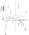
- FIG. 1 is a cross-sectional illustration of a borehole 1 including a distributed acoustic sensor system 100 according to an embodiment of the invention.
- a borehole 1 penetrates the earth 3 including a formation 4.
- a set of tools 10 may be lowered into the borehole 1 by a string 2.
- the string 2 may be a casing string, production string, an armored wireline, a slickline, coiled tubing, or a work string.
- the string 2 may be a drill string, and a drill would be included below the tools 10.
- the distributed acoustic sensor system 100 includes an optical fiber 110.
- the optical fiber 110 includes point reflectors 115.
- the three exemplary point reflectors 115 make up two interferometers 117a and 117b.
- the distributed acoustic sensor system 100 also includes a tunable laser 120, shown at the surface of the earth 3 in FIG. 1 .
- FIG. 2 details one embodiment in which the distributed acoustic sensor system 100 is used to monitor machinery 210.
- the machinery may be, for example, a submersible pump.
- the optical fiber 110 has point reflectors 115 on it that are coupled to the machinery 210.
- Each set of the point reflectors 115 shown in FIG. 2 are, for example, 10-20 cm apart and comprise a Fabry-Perot interferometer.
- the interferometer 117 may be a Michelson interferometer or a Mach-Zehnder interferometer rather than a Fabry-Perot interferometer.
- Each interferometer 117 comprised of a set of the point reflectors 115 in the present embodiment monitors the machinery 210 in the following way.
- the tunable laser 120 emits a range of sequential wavelengths over some finite time interval.
- the return signals from a pair of the point reflectors 115, with no other contributing component, would interfere with each other to generate a sine wave pattern whose frequency reflects the spacing of the point reflectors 115 (i.e. each interferometer 117 output would be a sine wave pattern).
- the signal received at the surface from each interferometer 117 comprised of a set of the point reflectors 115 will not be a pure sine wave pattern but will, instead, include other signal components contributed by the vibration of the machinery 210 to which the point reflectors 115 are coupled, as well as signal components due to non-linear tuning of the tunable laser 120.
- Embodiments using a tunable laser 120 with a linear tuning characteristic avoid these contributing signal components.
- the surface processing system 130 can determine the interference component or the component of acoustic signal attributable to the machinery 210 to which the point reflectors 115 are coupled.
- the phase shift caused by the machinery 210 vibration can be thought of as a modulation of the carrier, and the modulation can be processed and determined as detailed below.
- changes e.g., an increase in vibration
- changes can be determined and dealt with. For example, if a rapid increase in the vibrational component of the machinery 210 is determined, it may indicate an imminent failure in the machinery 210.
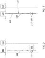
- FIG. 3 details one embodiment of using the distributed acoustic sensor system 100 to monitor a sandscreen 310.
- the optical fiber 110 may be directly coupled to the sandscreen 310 or may be coupled to the sandscreen 310 through another component 320 (e.g., Fiber Express Tube TM ).
- the tunable laser 120 sweeps a range of wavelengths over a time interval as in the embodiment discussed with reference to FIG. 2 .
- the resulting interferometer signal (where the interferometer 117 is comprised of the pair of the point reflectors 115 in the embodiment shown in FIG. 3 ) includes a component due to flow through the sandscreen 310.
- flow of formation fluid through the sandscreen 310 modulates the sine pattern and can be processed and detected by the surface processing system 130.
- a pipe the length of 30.48m (100 feet) may cover a reservoir.
- the flow of oil can be localized along the pipe. The processing of the interferometer signal to determine the component attributable to the disturbance (e.g., vibration, flow) according to the embodiments shown in FIGs. 2 and 3 is detailed next.
- FIGs. 4-8 detail the processing of an exemplary interferometer signal received by the distributed acoustic sensor system 100.
- the processing may be executed by the surface processing system 130, for example.
- FIG. 4 shows an exemplary received signal 410 for a period of time (x-axis 420). Amplitude is shown on the y-axis (430).
- the exemplary received signal 410 includes interferometer output for a single interferometer 117 but a received signal 410 in a distributed acoustic sensor system 100 that includes more interferometers 117 will include more interferometer outputs.
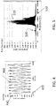
- a Fourier transform is taken of the received signal 410 to provide the signal 510 in the frequency domain (x-axis 520).
- the component 530 as well as portions of the signal 510, are generated because of non-linear characteristics of the tunable laser 120. If the interferometer output resulted from a tunable laser 120 with linear tuning characteristics, the component 530 (and contributions to the signal 510) would not be present. As noted with regard to FIG. 4 , a distributed acoustic sensor system 100 with two or more interferometers 117 would receive two or more interferometer outputs and, thus, would include two or more signals 510 in the frequency domain.
- a bandpass filter is used to isolate each of the signals 510, and then an inverse Fourier transform is taken of each isolated signal 510 to provide the exemplary complex signal (real component 610 and imaginary component 620) in the time domain (x-axis 630) shown in FIG. 6 .
- a bandpass filter is used to isolate each of the signals 510, and then an inverse Fourier transform is taken of each isolated signal 510 to provide the exemplary complex signal (real component 610 and imaginary component 620) in the time domain (x-axis 630) shown in FIG. 6 .
- phase 710 and phase modulation 720 By taking the arc tangent of (the real component 610/the imaginary component 620) and then performing phase unwrapping on the resulting phase, the phase 710 and phase modulation 720 over time (x-axis 730) result, as shown in FIG. 7 .
- the phase modulation 720 which is the portion of interest, reflects the contribution of the downhole parameter of interest (e.g., vibration, flow) to interferometer output and also the contribution of the tunable laser 120 when the tunable laser 120 does not have a linear tuning characteristic. Thus, if there were no vibration, flow, or other contribution to the interferometer output and the tunable laser 120 had linear tuning characteristics, the phase modulation 720 would be a flat line at 0. As noted above, the portion of interest is the phase modulation 720 because it includes the vibration or flow contribution to the interferometer output.
- the downhole parameter of interest e.g., vibration, flow
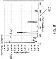
- the frequency (x-axis 820) and amplitude (y-axis 830) (shown on a log scale) of the vibration may be determined.
- the interferometer output includes a vibration component induced at 137 Hz.
- FIG. 8 shows this component 810 at 137 Hz.
- phase modulation 720 (indicating vibration or flow) can be localized within the borehole 1 in the following way.
- the results shown in FIGs. 7 and 8 are determined for each of the interferometers 117.
- the location of flow for example, can be determined based on the location of the point reflectors 115 that make up the particular interferometer 117.
- Embodiments of the distributed acoustic sensor system 100 discussed below include additional types of interferometers 117 and discuss additional methods of determining the location of the interferometer 117.
- the distributed acoustic sensor system 100 discussed herein may be used for vertical seismic profiling or fracing in addition to vibration and flow monitoring.
- FIG. 9 depicts another embodiment of the distributed acoustic sensor system 100 using fiber Bragg gratings (FBGs) 910.
- FBGs 910 rather than point reflectors 115 are used for the interferometer 117.
- the FBGs 910 act as reflectors around the resonant wavelength of the Bragg grating.
- the number and distribution of the Bragg gratings may be varied to affect the reflective characteristic.
- the interferometer signal generated by the FBGs 910 is processed to isolate the phase perturbation caused by the target disturbance (e.g., vibration of machinery 210, flow through sandscreen 310).
- the target disturbance e.g., vibration of machinery 210, flow through sandscreen 310.
- FIG. 10 depicts another embodiment of the distributed acoustic sensor system 100 using Rayleigh backscatter. This embodiment is based on the fact that, even without any reflector or Bragg grating along the optical fiber 110, Rayleigh backscatter is generated at every point along the optical fiber 110.
- a reference reflector 1010 at a known location along the optical fiber 110, each point on the optical fiber 110 acts as an interferometer 117 in conjunction with the reference reflector 1010.
- an area of interest e.g., part of a machinery 210, sandscreen 310) may be isolated for processing of the interferometer signal.
- a 20 cm spacing within 500 m of the reference reflector 1010 may be isolated.
- the interferometer signal generated by the Rayleigh backscatter from the isolated length and the reference reflector 1010 may then be processed to determine the phase modulation.
- the phase modulation indicates the vibration in the case of the area of interest being part of a machinery 210 (like a submersible pump) or flow in the case of the area of interest being part of a sandscreen 310.
- the reference reflector 1010 is a point reflector 115. In other embodiments, the reference reflector 1010 may be an FBG 910.
- a reference reflector may be used in conjunction with the point reflectors 115 or FBGs 910 discussed with reference to FIGs. 2, 3 , and 6 , as well. That is, when more than two point reflectors 115 or FBGs 910 are used, the spacing between adjacent point reflectors 115 or FBGs 910 is varied so that a given pair of the point reflectors 115 or FBGs 910 has a unique distance between them and is thereby distinguishable from any other pair along the optical fiber 110.
- the point reflectors 115 or FBGs 910 may be placed at known locations (a priori knowledge) or a reference reflector 1010 may be used to make the determination.
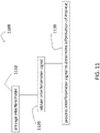
- FIG. 11 is a flow diagram of an exemplary method 1100 of using distributed downhole acoustic sensing.
- arranging the interferometer includes arranging point reflectors 115 as discussed with reference to FIGs. 2 and 3 or FBGs 910, as discussed with reference to FIG. 9 , with or without a reference reflector 1010, or only including a reference reflector 1010 as discussed with reference to FIG. 10 .
- obtaining the interferometer signal includes transmitting a range of wavelengths with a tunable laser 120 and receiving the interferometer signal. The interferometer signal may be received at the surface.
- processing the interferometer signal to determine the information of interest includes determining the vibration and, over time, monitoring changes in vibrations of a part of a machinery 210 such as a submersible pump. Processing at block 1130 also includes determining flow at location of a sandscreen 310. Processing at block 1130 also includes performing vertical seismic profiling or fracing. The processing at block 1130 may be in accordance with the discussion above with reference to FIGs. 4-8 .
Landscapes
- Engineering & Computer Science (AREA)
- Remote Sensing (AREA)
- Physics & Mathematics (AREA)
- Life Sciences & Earth Sciences (AREA)
- Acoustics & Sound (AREA)
- Environmental & Geological Engineering (AREA)
- Geology (AREA)
- General Life Sciences & Earth Sciences (AREA)
- General Physics & Mathematics (AREA)
- Geophysics (AREA)
- Measurement Of Mechanical Vibrations Or Ultrasonic Waves (AREA)
- Investigating Or Analyzing Materials By The Use Of Ultrasonic Waves (AREA)
Applications Claiming Priority (2)
| Application Number | Priority Date | Filing Date | Title |
|---|---|---|---|
| US13/690,324 US9784862B2 (en) | 2012-11-30 | 2012-11-30 | Distributed downhole acousting sensing |
| PCT/US2013/067252 WO2014085012A1 (en) | 2012-11-30 | 2013-10-29 | Distributed downhole acousting sensing |
Publications (3)
| Publication Number | Publication Date |
|---|---|
| EP2925962A1 EP2925962A1 (en) | 2015-10-07 |
| EP2925962A4 EP2925962A4 (en) | 2016-08-10 |
| EP2925962B1 true EP2925962B1 (en) | 2022-04-20 |
Family
ID=50824111
Family Applications (1)
| Application Number | Title | Priority Date | Filing Date |
|---|---|---|---|
| EP13858894.2A Active EP2925962B1 (en) | 2012-11-30 | 2013-10-29 | Distributed downhole acousting sensing |
Country Status (7)
| Country | Link |
|---|---|
| US (1) | US9784862B2 (pt) |
| EP (1) | EP2925962B1 (pt) |
| AU (1) | AU2013353368B2 (pt) |
| BR (1) | BR112015011854B1 (pt) |
| CA (1) | CA2892374C (pt) |
| DK (1) | DK2925962T3 (pt) |
| WO (1) | WO2014085012A1 (pt) |
Families Citing this family (21)
| Publication number | Priority date | Publication date | Assignee | Title |
|---|---|---|---|---|
| CA2938526C (en) | 2014-03-24 | 2019-11-12 | Halliburton Energy Services, Inc. | Well tools with vibratory telemetry to optical line therein |
| US20160076932A1 (en) * | 2014-09-11 | 2016-03-17 | Trican Well Service, Ltd. | Distributed acoustic sensing to optimize coil tubing milling performance |
| AU2017246521B2 (en) | 2016-04-07 | 2023-02-02 | Bp Exploration Operating Company Limited | Detecting downhole sand ingress locations |
| BR112018070565A2 (pt) | 2016-04-07 | 2019-02-12 | Bp Exploration Operating Company Limited | detecção de eventos de fundo de poço usando características de domínio da frequência acústicas |
| EP3583296B1 (en) | 2017-03-31 | 2021-07-21 | BP Exploration Operating Company Limited | Well and overburden monitoring using distributed acoustic sensors |
| EA202090528A1 (ru) | 2017-08-23 | 2020-07-10 | Бп Эксплорейшн Оперейтинг Компани Лимитед | Обнаружение мест скважинных пескопроявлений |
| CN109424356B (zh) * | 2017-08-25 | 2021-08-27 | 中国石油化工股份有限公司 | 钻井液漏失位置检测系统及方法 |
| EP3695099A2 (en) | 2017-10-11 | 2020-08-19 | BP Exploration Operating Company Limited | Detecting events using acoustic frequency domain features |
| US11649717B2 (en) | 2018-09-17 | 2023-05-16 | Saudi Arabian Oil Company | Systems and methods for sensing downhole cement sheath parameters |
| US11536117B2 (en) | 2018-10-08 | 2022-12-27 | Halliburton Energy Services, Inc. | Monitoring fluid characteristics downhole |
| US11859488B2 (en) | 2018-11-29 | 2024-01-02 | Bp Exploration Operating Company Limited | DAS data processing to identify fluid inflow locations and fluid type |
| WO2020122856A1 (en) | 2018-12-10 | 2020-06-18 | Halliburton Energy Services, Inc. | Flow characterization tool |
| GB201820331D0 (en) | 2018-12-13 | 2019-01-30 | Bp Exploration Operating Co Ltd | Distributed acoustic sensing autocalibration |
| US10989047B2 (en) | 2019-05-10 | 2021-04-27 | Halliburton Energy Services, Inc. | Systems and methods for sand flow detection and quantification |
| US11231315B2 (en) * | 2019-09-05 | 2022-01-25 | Baker Hughes Oilfield Operations Llc | Acoustic detection of position of a component of a fluid control device |
| WO2021073741A1 (en) | 2019-10-17 | 2021-04-22 | Lytt Limited | Fluid inflow characterization using hybrid das/dts measurements |
| CA3154435C (en) | 2019-10-17 | 2023-03-28 | Lytt Limited | Inflow detection using dts features |
| WO2021093974A1 (en) | 2019-11-15 | 2021-05-20 | Lytt Limited | Systems and methods for draw down improvements across wellbores |
| EP4165284A1 (en) | 2020-06-11 | 2023-04-19 | Lytt Limited | Systems and methods for subterranean fluid flow characterization |
| CA3182376A1 (en) | 2020-06-18 | 2021-12-23 | Cagri CERRAHOGLU | Event model training using in situ data |
| US11946824B2 (en) | 2021-12-13 | 2024-04-02 | Saudi Arabian Oil Company | Methods for determining sensor channel location in distributed sensing of fiber-optic cables |
Citations (3)
| Publication number | Priority date | Publication date | Assignee | Title |
|---|---|---|---|---|
| WO2011067554A1 (en) * | 2009-12-02 | 2011-06-09 | Qinetiq Limited | Phase based sensing |
| US20120046866A1 (en) * | 2010-08-23 | 2012-02-23 | Schlumberger Technology Corporation | Oilfield applications for distributed vibration sensing technology |
| US20120278043A1 (en) * | 2011-04-08 | 2012-11-01 | Qinetiq Limited | Fibre Optic Distributed Sensing |
Family Cites Families (26)
| Publication number | Priority date | Publication date | Assignee | Title |
|---|---|---|---|---|
| GB2290869B (en) * | 1994-06-28 | 1998-07-15 | Western Atlas Int Inc | Slickline conveyed wellbore seismic receiver |
| CA2524554C (en) | 1997-05-02 | 2007-11-27 | Sensor Highway Limited | Electrical energy from a wellbore light cell |
| GB9710057D0 (en) | 1997-05-19 | 1997-07-09 | King S College London | Distributed sensing system |
| US5987197A (en) * | 1997-11-07 | 1999-11-16 | Cidra Corporation | Array topologies for implementing serial fiber Bragg grating interferometer arrays |
| EP1058823B1 (en) * | 1998-12-17 | 2006-05-17 | Chevron USA, Inc. | Apparatus and method for protecting optical devices in hostile environments |
| US6601671B1 (en) * | 2000-07-10 | 2003-08-05 | Weatherford/Lamb, Inc. | Method and apparatus for seismically surveying an earth formation in relation to a borehole |
| US20020196993A1 (en) * | 2001-06-26 | 2002-12-26 | Schroeder Robert J. | Fiber optic supported sensor-telemetry system |
| US20070047867A1 (en) * | 2003-10-03 | 2007-03-01 | Goldner Eric L | Downhole fiber optic acoustic sand detector |
| GB0424305D0 (en) | 2004-11-03 | 2004-12-01 | Polarmetrix Ltd | Phase-disturbance location and measurement in optical-fibre interferometric reflectometry |
| US20060126073A1 (en) | 2004-12-09 | 2006-06-15 | Intune Technologies Limited | Displacement measuring interferometer system and method using tunable lasers |
| US7282698B2 (en) | 2005-09-08 | 2007-10-16 | Baker Hughes Incorporated | System and method for monitoring a well |
| US7538860B2 (en) * | 2007-08-17 | 2009-05-26 | The United States Of America As Represented By The Administrator Of The National Aeronautics And Space Administration | System and method for determination of the reflection wavelength of multiple low-reflectivity bragg gratings in a sensing optical fiber |
| US7946341B2 (en) * | 2007-11-02 | 2011-05-24 | Schlumberger Technology Corporation | Systems and methods for distributed interferometric acoustic monitoring |
| US8515675B2 (en) * | 2008-04-02 | 2013-08-20 | Bakes Hughes Incorporated | Method for analyzing strain data |
| US7894061B2 (en) * | 2008-06-19 | 2011-02-22 | Qorex Llc | Polarization based fiber optic downhole flowmeter |
| US8020616B2 (en) * | 2008-08-15 | 2011-09-20 | Schlumberger Technology Corporation | Determining a status in a wellbore based on acoustic events detected by an optical fiber mechanism |
| CA2708843C (en) * | 2009-07-01 | 2014-01-21 | Baker Hughes Incorporated | System to measure vibrations using fiber optic sensors |
| US8208767B2 (en) * | 2009-11-10 | 2012-06-26 | Baker Hughes Incorporated | Sensor array configuration for extending useful sensing length of a swept-wavelength interferometry based system |
| US9267821B2 (en) * | 2010-01-28 | 2016-02-23 | Baker Hughes Incorporated | Combined swept-carrier and swept-modulation frequency optical frequency domain reflectometry |
| US8605542B2 (en) * | 2010-05-26 | 2013-12-10 | Schlumberger Technology Corporation | Detection of seismic signals using fiber optic distributed sensors |
| WO2012030814A2 (en) * | 2010-09-01 | 2012-03-08 | Schlumberger Canada Limited | Distributed fiber optic sensor system with improved linearity |
| US9200508B2 (en) | 2011-01-06 | 2015-12-01 | Baker Hughes Incorporated | Method and apparatus for monitoring vibration using fiber optic sensors |
| US20120237205A1 (en) | 2011-03-16 | 2012-09-20 | Baker Hughes Incorporated | System and method to compensate for arbitrary optical fiber lead-ins in an optical frequency domain reflectometry system |
| US8614795B2 (en) * | 2011-07-21 | 2013-12-24 | Baker Hughes Incorporated | System and method of distributed fiber optic sensing including integrated reference path |
| JP5333538B2 (ja) * | 2011-07-27 | 2013-11-06 | 株式会社デンソー | 弾性表面波センサ |
| US20140126332A1 (en) * | 2012-11-08 | 2014-05-08 | Halliburton Energy Services, Inc. | Verification of well tool operation with distributed acoustic sensing system |
-
2012
- 2012-11-30 US US13/690,324 patent/US9784862B2/en active Active
-
2013
- 2013-10-29 CA CA2892374A patent/CA2892374C/en active Active
- 2013-10-29 WO PCT/US2013/067252 patent/WO2014085012A1/en active Application Filing
- 2013-10-29 EP EP13858894.2A patent/EP2925962B1/en active Active
- 2013-10-29 DK DK13858894.2T patent/DK2925962T3/da active
- 2013-10-29 AU AU2013353368A patent/AU2013353368B2/en active Active
- 2013-10-29 BR BR112015011854-2A patent/BR112015011854B1/pt active IP Right Grant
Patent Citations (3)
| Publication number | Priority date | Publication date | Assignee | Title |
|---|---|---|---|---|
| WO2011067554A1 (en) * | 2009-12-02 | 2011-06-09 | Qinetiq Limited | Phase based sensing |
| US20120046866A1 (en) * | 2010-08-23 | 2012-02-23 | Schlumberger Technology Corporation | Oilfield applications for distributed vibration sensing technology |
| US20120278043A1 (en) * | 2011-04-08 | 2012-11-01 | Qinetiq Limited | Fibre Optic Distributed Sensing |
Also Published As
| Publication number | Publication date |
|---|---|
| AU2013353368B2 (en) | 2018-02-15 |
| US9784862B2 (en) | 2017-10-10 |
| BR112015011854A2 (pt) | 2017-07-11 |
| EP2925962A4 (en) | 2016-08-10 |
| CA2892374A1 (en) | 2014-06-05 |
| AU2013353368A1 (en) | 2015-05-21 |
| WO2014085012A1 (en) | 2014-06-05 |
| US20140150548A1 (en) | 2014-06-05 |
| CA2892374C (en) | 2018-03-20 |
| BR112015011854B1 (pt) | 2021-08-03 |
| DK2925962T3 (da) | 2022-05-09 |
| EP2925962A1 (en) | 2015-10-07 |
Similar Documents
| Publication | Publication Date | Title |
|---|---|---|
| EP2925962B1 (en) | Distributed downhole acousting sensing | |
| US11421527B2 (en) | Simultaneous distributed measurements on optical fiber | |
| CA2921023C (en) | Acoustic sensing system and method of acoustically monitoring a tool | |
| AU2011353668B2 (en) | Method and apparatus for monitoring vibration using fiber optic sensors | |
| US20140110124A1 (en) | Wellbore leak detection systems and methods of using the same | |
| CA2946279C (en) | Distributed acoustic sensing using low pulse repetition rates | |
| CA2924957C (en) | Fiber optic distributed acoustic measurements via fmcw interrogation | |
| CA2944352A1 (en) | Attenuation correction for distributed temperature sensors using antistokes to rayleigh ratio | |
| Liu et al. | The Applications of Interferometric Fiber-Optic Sensors in Oilfield | |
| NO20160605A1 (en) | Use of Bragg Gratings with Coherent OTDR | |
| US20140230536A1 (en) | Distributed acoustic monitoring via time-sheared incoherent frequency domain reflectometry |
Legal Events
| Date | Code | Title | Description |
|---|---|---|---|
| PUAI | Public reference made under article 153(3) epc to a published international application that has entered the european phase |
Free format text: ORIGINAL CODE: 0009012 |
|
| 17P | Request for examination filed |
Effective date: 20150626 |
|
| AK | Designated contracting states |
Kind code of ref document: A1 Designated state(s): AL AT BE BG CH CY CZ DE DK EE ES FI FR GB GR HR HU IE IS IT LI LT LU LV MC MK MT NL NO PL PT RO RS SE SI SK SM TR |
|
| AX | Request for extension of the european patent |
Extension state: BA ME |
|
| DAX | Request for extension of the european patent (deleted) | ||
| RA4 | Supplementary search report drawn up and despatched (corrected) |
Effective date: 20160711 |
|
| RIC1 | Information provided on ipc code assigned before grant |
Ipc: E21B 47/135 20120101ALI20160705BHEP Ipc: E21B 47/0224 20120101AFI20160705BHEP Ipc: G01V 1/22 20060101ALI20160705BHEP Ipc: G01V 1/40 20060101ALI20160705BHEP |
|
| STAA | Information on the status of an ep patent application or granted ep patent |
Free format text: STATUS: EXAMINATION IS IN PROGRESS |
|
| 17Q | First examination report despatched |
Effective date: 20171221 |
|
| STAA | Information on the status of an ep patent application or granted ep patent |
Free format text: STATUS: EXAMINATION IS IN PROGRESS |
|
| GRAP | Despatch of communication of intention to grant a patent |
Free format text: ORIGINAL CODE: EPIDOSNIGR1 |
|
| STAA | Information on the status of an ep patent application or granted ep patent |
Free format text: STATUS: GRANT OF PATENT IS INTENDED |
|
| INTG | Intention to grant announced |
Effective date: 20211202 |
|
| GRAS | Grant fee paid |
Free format text: ORIGINAL CODE: EPIDOSNIGR3 |
|
| GRAA | (expected) grant |
Free format text: ORIGINAL CODE: 0009210 |
|
| STAA | Information on the status of an ep patent application or granted ep patent |
Free format text: STATUS: THE PATENT HAS BEEN GRANTED |
|
| RAP3 | Party data changed (applicant data changed or rights of an application transferred) |
Owner name: BAKER HUGHES HOLDINGS LLC |
|
| AK | Designated contracting states |
Kind code of ref document: B1 Designated state(s): AL AT BE BG CH CY CZ DE DK EE ES FI FR GB GR HR HU IE IS IT LI LT LU LV MC MK MT NL NO PL PT RO RS SE SI SK SM TR |
|
| REG | Reference to a national code |
Ref country code: GB Ref legal event code: FG4D |
|
| REG | Reference to a national code |
Ref country code: CH Ref legal event code: EP |
|
| REG | Reference to a national code |
Ref country code: DK Ref legal event code: T3 Effective date: 20220505 |
|
| REG | Reference to a national code |
Ref country code: IE Ref legal event code: FG4D |
|
| REG | Reference to a national code |
Ref country code: DE Ref legal event code: R096 Ref document number: 602013081473 Country of ref document: DE |
|
| REG | Reference to a national code |
Ref country code: AT Ref legal event code: REF Ref document number: 1485287 Country of ref document: AT Kind code of ref document: T Effective date: 20220515 |
|
| REG | Reference to a national code |
Ref country code: NO Ref legal event code: T2 Effective date: 20220420 |
|
| REG | Reference to a national code |
Ref country code: LT Ref legal event code: MG9D |
|
| REG | Reference to a national code |
Ref country code: NL Ref legal event code: MP Effective date: 20220420 |
|
| REG | Reference to a national code |
Ref country code: AT Ref legal event code: MK05 Ref document number: 1485287 Country of ref document: AT Kind code of ref document: T Effective date: 20220420 |
|
| PG25 | Lapsed in a contracting state [announced via postgrant information from national office to epo] |
Ref country code: NL Free format text: LAPSE BECAUSE OF FAILURE TO SUBMIT A TRANSLATION OF THE DESCRIPTION OR TO PAY THE FEE WITHIN THE PRESCRIBED TIME-LIMIT Effective date: 20220420 |
|
| PG25 | Lapsed in a contracting state [announced via postgrant information from national office to epo] |
Ref country code: SE Free format text: LAPSE BECAUSE OF FAILURE TO SUBMIT A TRANSLATION OF THE DESCRIPTION OR TO PAY THE FEE WITHIN THE PRESCRIBED TIME-LIMIT Effective date: 20220420 Ref country code: PT Free format text: LAPSE BECAUSE OF FAILURE TO SUBMIT A TRANSLATION OF THE DESCRIPTION OR TO PAY THE FEE WITHIN THE PRESCRIBED TIME-LIMIT Effective date: 20220822 Ref country code: LT Free format text: LAPSE BECAUSE OF FAILURE TO SUBMIT A TRANSLATION OF THE DESCRIPTION OR TO PAY THE FEE WITHIN THE PRESCRIBED TIME-LIMIT Effective date: 20220420 Ref country code: HR Free format text: LAPSE BECAUSE OF FAILURE TO SUBMIT A TRANSLATION OF THE DESCRIPTION OR TO PAY THE FEE WITHIN THE PRESCRIBED TIME-LIMIT Effective date: 20220420 Ref country code: GR Free format text: LAPSE BECAUSE OF FAILURE TO SUBMIT A TRANSLATION OF THE DESCRIPTION OR TO PAY THE FEE WITHIN THE PRESCRIBED TIME-LIMIT Effective date: 20220721 Ref country code: FI Free format text: LAPSE BECAUSE OF FAILURE TO SUBMIT A TRANSLATION OF THE DESCRIPTION OR TO PAY THE FEE WITHIN THE PRESCRIBED TIME-LIMIT Effective date: 20220420 Ref country code: ES Free format text: LAPSE BECAUSE OF FAILURE TO SUBMIT A TRANSLATION OF THE DESCRIPTION OR TO PAY THE FEE WITHIN THE PRESCRIBED TIME-LIMIT Effective date: 20220420 Ref country code: BG Free format text: LAPSE BECAUSE OF FAILURE TO SUBMIT A TRANSLATION OF THE DESCRIPTION OR TO PAY THE FEE WITHIN THE PRESCRIBED TIME-LIMIT Effective date: 20220720 Ref country code: AT Free format text: LAPSE BECAUSE OF FAILURE TO SUBMIT A TRANSLATION OF THE DESCRIPTION OR TO PAY THE FEE WITHIN THE PRESCRIBED TIME-LIMIT Effective date: 20220420 |
|
| PG25 | Lapsed in a contracting state [announced via postgrant information from national office to epo] |
Ref country code: RS Free format text: LAPSE BECAUSE OF FAILURE TO SUBMIT A TRANSLATION OF THE DESCRIPTION OR TO PAY THE FEE WITHIN THE PRESCRIBED TIME-LIMIT Effective date: 20220420 Ref country code: PL Free format text: LAPSE BECAUSE OF FAILURE TO SUBMIT A TRANSLATION OF THE DESCRIPTION OR TO PAY THE FEE WITHIN THE PRESCRIBED TIME-LIMIT Effective date: 20220420 Ref country code: LV Free format text: LAPSE BECAUSE OF FAILURE TO SUBMIT A TRANSLATION OF THE DESCRIPTION OR TO PAY THE FEE WITHIN THE PRESCRIBED TIME-LIMIT Effective date: 20220420 Ref country code: IS Free format text: LAPSE BECAUSE OF FAILURE TO SUBMIT A TRANSLATION OF THE DESCRIPTION OR TO PAY THE FEE WITHIN THE PRESCRIBED TIME-LIMIT Effective date: 20220820 |
|
| REG | Reference to a national code |
Ref country code: DE Ref legal event code: R097 Ref document number: 602013081473 Country of ref document: DE |
|
| PG25 | Lapsed in a contracting state [announced via postgrant information from national office to epo] |
Ref country code: SM Free format text: LAPSE BECAUSE OF FAILURE TO SUBMIT A TRANSLATION OF THE DESCRIPTION OR TO PAY THE FEE WITHIN THE PRESCRIBED TIME-LIMIT Effective date: 20220420 Ref country code: SK Free format text: LAPSE BECAUSE OF FAILURE TO SUBMIT A TRANSLATION OF THE DESCRIPTION OR TO PAY THE FEE WITHIN THE PRESCRIBED TIME-LIMIT Effective date: 20220420 Ref country code: RO Free format text: LAPSE BECAUSE OF FAILURE TO SUBMIT A TRANSLATION OF THE DESCRIPTION OR TO PAY THE FEE WITHIN THE PRESCRIBED TIME-LIMIT Effective date: 20220420 Ref country code: EE Free format text: LAPSE BECAUSE OF FAILURE TO SUBMIT A TRANSLATION OF THE DESCRIPTION OR TO PAY THE FEE WITHIN THE PRESCRIBED TIME-LIMIT Effective date: 20220420 Ref country code: CZ Free format text: LAPSE BECAUSE OF FAILURE TO SUBMIT A TRANSLATION OF THE DESCRIPTION OR TO PAY THE FEE WITHIN THE PRESCRIBED TIME-LIMIT Effective date: 20220420 |
|
| PLBE | No opposition filed within time limit |
Free format text: ORIGINAL CODE: 0009261 |
|
| STAA | Information on the status of an ep patent application or granted ep patent |
Free format text: STATUS: NO OPPOSITION FILED WITHIN TIME LIMIT |
|
| 26N | No opposition filed |
Effective date: 20230123 |
|
| PG25 | Lapsed in a contracting state [announced via postgrant information from national office to epo] |
Ref country code: AL Free format text: LAPSE BECAUSE OF FAILURE TO SUBMIT A TRANSLATION OF THE DESCRIPTION OR TO PAY THE FEE WITHIN THE PRESCRIBED TIME-LIMIT Effective date: 20220420 |
|
| REG | Reference to a national code |
Ref country code: DE Ref legal event code: R119 Ref document number: 602013081473 Country of ref document: DE |
|
| PG25 | Lapsed in a contracting state [announced via postgrant information from national office to epo] |
Ref country code: SI Free format text: LAPSE BECAUSE OF FAILURE TO SUBMIT A TRANSLATION OF THE DESCRIPTION OR TO PAY THE FEE WITHIN THE PRESCRIBED TIME-LIMIT Effective date: 20220420 Ref country code: MC Free format text: LAPSE BECAUSE OF FAILURE TO SUBMIT A TRANSLATION OF THE DESCRIPTION OR TO PAY THE FEE WITHIN THE PRESCRIBED TIME-LIMIT Effective date: 20220420 |
|
| REG | Reference to a national code |
Ref country code: CH Ref legal event code: PL |
|
| REG | Reference to a national code |
Ref country code: BE Ref legal event code: MM Effective date: 20221031 |
|
| PG25 | Lapsed in a contracting state [announced via postgrant information from national office to epo] |
Ref country code: LU Free format text: LAPSE BECAUSE OF NON-PAYMENT OF DUE FEES Effective date: 20221029 |
|
| P01 | Opt-out of the competence of the unified patent court (upc) registered |
Effective date: 20230526 |
|
| PG25 | Lapsed in a contracting state [announced via postgrant information from national office to epo] |
Ref country code: LI Free format text: LAPSE BECAUSE OF NON-PAYMENT OF DUE FEES Effective date: 20221031 Ref country code: FR Free format text: LAPSE BECAUSE OF NON-PAYMENT OF DUE FEES Effective date: 20221031 Ref country code: DE Free format text: LAPSE BECAUSE OF NON-PAYMENT OF DUE FEES Effective date: 20230503 Ref country code: CH Free format text: LAPSE BECAUSE OF NON-PAYMENT OF DUE FEES Effective date: 20221031 |
|
| PG25 | Lapsed in a contracting state [announced via postgrant information from national office to epo] |
Ref country code: BE Free format text: LAPSE BECAUSE OF NON-PAYMENT OF DUE FEES Effective date: 20221031 |
|
| PG25 | Lapsed in a contracting state [announced via postgrant information from national office to epo] |
Ref country code: IE Free format text: LAPSE BECAUSE OF NON-PAYMENT OF DUE FEES Effective date: 20221029 |
|
| PGFP | Annual fee paid to national office [announced via postgrant information from national office to epo] |
Ref country code: NO Payment date: 20230921 Year of fee payment: 11 Ref country code: GB Payment date: 20230920 Year of fee payment: 11 |
|
| PGFP | Annual fee paid to national office [announced via postgrant information from national office to epo] |
Ref country code: DK Payment date: 20230920 Year of fee payment: 11 |
|
| PG25 | Lapsed in a contracting state [announced via postgrant information from national office to epo] |
Ref country code: IT Free format text: LAPSE BECAUSE OF FAILURE TO SUBMIT A TRANSLATION OF THE DESCRIPTION OR TO PAY THE FEE WITHIN THE PRESCRIBED TIME-LIMIT Effective date: 20220420 |
|
| PG25 | Lapsed in a contracting state [announced via postgrant information from national office to epo] |
Ref country code: HU Free format text: LAPSE BECAUSE OF FAILURE TO SUBMIT A TRANSLATION OF THE DESCRIPTION OR TO PAY THE FEE WITHIN THE PRESCRIBED TIME-LIMIT; INVALID AB INITIO Effective date: 20131029 |
|
| PG25 | Lapsed in a contracting state [announced via postgrant information from national office to epo] |
Ref country code: CY Free format text: LAPSE BECAUSE OF FAILURE TO SUBMIT A TRANSLATION OF THE DESCRIPTION OR TO PAY THE FEE WITHIN THE PRESCRIBED TIME-LIMIT Effective date: 20220420 |