EP2925491B1 - Device in a rock drilling machine and rock drilling machine - Google Patents
Device in a rock drilling machine and rock drilling machine Download PDFInfo
- Publication number
- EP2925491B1 EP2925491B1 EP13859488.2A EP13859488A EP2925491B1 EP 2925491 B1 EP2925491 B1 EP 2925491B1 EP 13859488 A EP13859488 A EP 13859488A EP 2925491 B1 EP2925491 B1 EP 2925491B1
- Authority
- EP
- European Patent Office
- Prior art keywords
- valve
- rock drilling
- drilling machine
- abutment
- end walls
- Prior art date
- Legal status (The legal status is an assumption and is not a legal conclusion. Google has not performed a legal analysis and makes no representation as to the accuracy of the status listed.)
- Active
Links
Images

Classifications
-
- B—PERFORMING OPERATIONS; TRANSPORTING
- B25—HAND TOOLS; PORTABLE POWER-DRIVEN TOOLS; MANIPULATORS
- B25D—PERCUSSIVE TOOLS
- B25D9/00—Portable percussive tools with fluid-pressure drive, i.e. driven directly by fluids, e.g. having several percussive tool bits operated simultaneously
- B25D9/14—Control devices for the reciprocating piston
- B25D9/16—Valve arrangements therefor
- B25D9/20—Valve arrangements therefor involving a tubular-type slide valve
-
- B—PERFORMING OPERATIONS; TRANSPORTING
- B25—HAND TOOLS; PORTABLE POWER-DRIVEN TOOLS; MANIPULATORS
- B25D—PERCUSSIVE TOOLS
- B25D9/00—Portable percussive tools with fluid-pressure drive, i.e. driven directly by fluids, e.g. having several percussive tool bits operated simultaneously
- B25D9/14—Control devices for the reciprocating piston
-
- B—PERFORMING OPERATIONS; TRANSPORTING
- B25—HAND TOOLS; PORTABLE POWER-DRIVEN TOOLS; MANIPULATORS
- B25D—PERCUSSIVE TOOLS
- B25D9/00—Portable percussive tools with fluid-pressure drive, i.e. driven directly by fluids, e.g. having several percussive tool bits operated simultaneously
- B25D9/06—Means for driving the impulse member
- B25D9/12—Means for driving the impulse member comprising a built-in liquid motor, i.e. the tool being driven by hydraulic pressure
-
- B—PERFORMING OPERATIONS; TRANSPORTING
- B25—HAND TOOLS; PORTABLE POWER-DRIVEN TOOLS; MANIPULATORS
- B25D—PERCUSSIVE TOOLS
- B25D9/00—Portable percussive tools with fluid-pressure drive, i.e. driven directly by fluids, e.g. having several percussive tool bits operated simultaneously
- B25D9/14—Control devices for the reciprocating piston
- B25D9/16—Valve arrangements therefor
- B25D9/18—Valve arrangements therefor involving a piston-type slide valve
-
- E—FIXED CONSTRUCTIONS
- E21—EARTH OR ROCK DRILLING; MINING
- E21B—EARTH OR ROCK DRILLING; OBTAINING OIL, GAS, WATER, SOLUBLE OR MELTABLE MATERIALS OR A SLURRY OF MINERALS FROM WELLS
- E21B1/00—Percussion drilling
- E21B1/12—Percussion drilling with a reciprocating impulse member
- E21B1/24—Percussion drilling with a reciprocating impulse member the impulse member being a piston driven directly by fluid pressure
- E21B1/26—Percussion drilling with a reciprocating impulse member the impulse member being a piston driven directly by fluid pressure by liquid pressure
-
- F—MECHANICAL ENGINEERING; LIGHTING; HEATING; WEAPONS; BLASTING
- F15—FLUID-PRESSURE ACTUATORS; HYDRAULICS OR PNEUMATICS IN GENERAL
- F15B—SYSTEMS ACTING BY MEANS OF FLUIDS IN GENERAL; FLUID-PRESSURE ACTUATORS, e.g. SERVOMOTORS; DETAILS OF FLUID-PRESSURE SYSTEMS, NOT OTHERWISE PROVIDED FOR
- F15B13/00—Details of servomotor systems ; Valves for servomotor systems
- F15B13/02—Fluid distribution or supply devices characterised by their adaptation to the control of servomotors
-
- F—MECHANICAL ENGINEERING; LIGHTING; HEATING; WEAPONS; BLASTING
- F16—ENGINEERING ELEMENTS AND UNITS; GENERAL MEASURES FOR PRODUCING AND MAINTAINING EFFECTIVE FUNCTIONING OF MACHINES OR INSTALLATIONS; THERMAL INSULATION IN GENERAL
- F16K—VALVES; TAPS; COCKS; ACTUATING-FLOATS; DEVICES FOR VENTING OR AERATING
- F16K27/00—Construction of housing; Use of materials therefor
- F16K27/04—Construction of housing; Use of materials therefor of sliding valves
-
- F—MECHANICAL ENGINEERING; LIGHTING; HEATING; WEAPONS; BLASTING
- F16—ENGINEERING ELEMENTS AND UNITS; GENERAL MEASURES FOR PRODUCING AND MAINTAINING EFFECTIVE FUNCTIONING OF MACHINES OR INSTALLATIONS; THERMAL INSULATION IN GENERAL
- F16K—VALVES; TAPS; COCKS; ACTUATING-FLOATS; DEVICES FOR VENTING OR AERATING
- F16K27/00—Construction of housing; Use of materials therefor
- F16K27/04—Construction of housing; Use of materials therefor of sliding valves
- F16K27/041—Construction of housing; Use of materials therefor of sliding valves cylindrical slide valves
Definitions
- the invention relates to a device according to the preamble of claim 1 for a hydraulic rock drilling machine including a distribution valve arranged in connection with the rock drilling machine for controlling hydraulic flows to different parts of the rock drilling machine, wherein the distribution valve includes a valve body, which is arranged movable to and fro in axial directions inside a valve chamber and wherein the valve chamber is limited in axial direction by two valve end walls.
- the invention also relates to a hydraulic rock drilling machine including such a device.
- valve bushing can be produced so as to comprise one unit which includes on the one hand the control edges of the valve chamber co-operating with the valve body, on the one hand said abutment(-s), which in co-operation with the respective valve end wall defines the end position (or end positions) of the valve body, through the invention is ensured in an economic, efficient and secure manner that the elements of the valve chamber determining the control function are accurately positioned relative to each other.
- valve bushing lies against a housing wall whereon abuts also one of the valve end walls, which is also in this case fixed.
- a rear housing end wall 6 which closes the cylinder space 4.
- a distribution valve 7 for distributing pressure fluid to the drive chambers of the rock drilling machine for driving the impact piston 3 to and fro.
- the distribution valve 7 comprises a to and fro movable valve body 8 which is movable inside a valve bushing 9 between two end positions defined by abutments against a first valve end wall 10 and a second valve end wall 11, respectively.
- the valve bushing 9 limits a valve chamber 33 receiving the valve body 8 and exhibiting usual bores comprising openings of channels being connected to the distribution valve 7.
- the valve bushing is arranged to accurately define control edges for co-operation with corresponding control lands of the valve body 8.
- the first valve end wall 10 is influenced by pressure in a chamber 13, being permanently pressurized in operation of the rock drilling machine 1, said chamber 13 co-operating with a piston portion 25 on the first valve end wall 10. Because of this pressurization, the first valve end wall 10 is pressed in a direction towards the second valve end wall 11.
- valve body 8 When the channel 14, because of the movement of the impact piston 3, instead is relieved from pressure (not shown), the valve body 8 will be driven to the left in the Figure, such that the first abutment end 21 of the valve body 8 will come to abutment against the first end abutment 17 on the first valve end wall 10.
- FIG. 2 the distribution valve 7 is shown with its valve axis 18 parallel to the axis of the impact piston 3 and the work cylinder 4, being the axis of the percussion device of the rock drilling machine 1.
- This embodiment has the advantage that the rock drilling machine can be made slim and space-saving in its rear region. It also allows that said rear housing end wall 6 is common to the working cylinder and the distribution valve such that an otherwise necessary partition plane can be dispensed with. Through the construction with common axes and common rear housing end wall is achieved the advantage of lower machining costs and thereby reduced costs for the rock drilling machine. Further, the risk of moist and debris penetrating into the machine is reduced as well as the risk of failure because of unintentionally released screws.
- Fig. 4 shows a variant of a distribution valve similar to the one in Figs. 1 and 2 , but in this case (as in Fig. 3 ) it is intended to illustrate a distribution valve without a valve bushing.
- "Valve space” is in this case "valve chamber”.
- a chamber 13" is pressurized with a constant pressure.
- 12" indicates an abutment in the housing, which can be a machine housing of the rock drilling machine or a valve housing.
- the abutment 12" is suitably produced through boring from the left, which is a direction opposite to the opening of the bore of the space for the distribution valve as seen in all embodiments.
- a lid for the further bore is indicated with 29.
Landscapes
- Engineering & Computer Science (AREA)
- Mechanical Engineering (AREA)
- Fluid Mechanics (AREA)
- Physics & Mathematics (AREA)
- General Engineering & Computer Science (AREA)
- Geology (AREA)
- Mining & Mineral Resources (AREA)
- Life Sciences & Earth Sciences (AREA)
- Environmental & Geological Engineering (AREA)
- General Life Sciences & Earth Sciences (AREA)
- Geochemistry & Mineralogy (AREA)
- Earth Drilling (AREA)
- Drilling And Exploitation, And Mining Machines And Methods (AREA)
- Percussive Tools And Related Accessories (AREA)
Description
- The invention relates to a device according to the preamble of claim 1 for a hydraulic rock drilling machine including a distribution valve arranged in connection with the rock drilling machine for controlling hydraulic flows to different parts of the rock drilling machine, wherein the distribution valve includes a valve body, which is arranged movable to and fro in axial directions inside a valve chamber and wherein the valve chamber is limited in axial direction by two valve end walls. The invention also relates to a hydraulic rock drilling machine including such a device.
- There are previously known hydraulic rock drilling machines that are controlled with the aid of a distribution valve which is arranged in connection with the percussion device. The distribution valve aims to provide intermittent pressurizing of the driving chamber for the impact piston in order to achieve desired percussive function.
- Distribution valves so far known function well but require precision machining in order to guarantee reliable valve function, in particular in respect of today's rock drilling machines with increased percussive frequencies. This influences the costs of the valve and thereby of the rock drilling machine as a whole negatively.
- As an example of the background art can be mentioned
US 2,034,122 A1 , which describes a device according to the preamble of claim 1 as well as a rock drilling machine including a valve with a removable valve end wall. - It is an aim of the present invention to provide a further developed device as per claim 1 for a hydraulic rock drilling machine to suggest an economically produced device in connection with a distribution valve.
- This aim is obtained in a device according to claim 1 when at least one of the valve end walls is movable in an axial direction against an abutment in such a way that it defines a fixed end position for the valve body, that a pressing device is arranged for pressing said at least one of the valve end walls in a direction of the second one of said valve end walls and against said abutment, and that said pressing device includes an end wall piston portion arranged on said at least one of the valve end walls and being received in a cylinder portion to be pressurized in order to drive the valve end wall against said abutment during pressurizing.
- Hereby is obtained that the valve will become more simple and more economic to produce and to integrate into a rock drilling machine. This is because through the invention it is achieved that the machining operation for producing a defined axial position of a bottom of a bottom hole accurately and with high tolerances can be dispensed with.
- Instead, the respective valve end wall is influenced by a pressing device to be normally pressed against said abutment axially in a direction towards the second valve end wall of the distribution valve in order to achieve a fixed end position.
- Instead this results in that a defined abutment can be provided which can be made with high precision and to a considerable lower cost than what is the case for creating a defined position of a bottom hole. The abutment can be formed in the valve housing or on a specially provided sleeve or the like being arranged between the two valve end walls.
- Said cylinder portion is preferably provided with a connection to a hydraulic pressure source. The hydraulic pressure source is preferably a rock drilling machine system pressure source which economically advantageously results in that a pressure source already existing in the machine can be used. Such a system pressure source can be the source e.g. for any one of percussion pressure, rotation pressure and damping pressure.
- It is preferred that the valve chamber in a radial direction is limited by a valve bushing, which is formed with said abutment. This way the position of said abutment(-s) and thereby the end positions of the valve body can be determined and be provided economically with high position.
- Because the valve bushing can be produced so as to comprise one unit which includes on the one hand the control edges of the valve chamber co-operating with the valve body, on the one hand said abutment(-s), which in co-operation with the respective valve end wall defines the end position (or end positions) of the valve body, through the invention is ensured in an economic, efficient and secure manner that the elements of the valve chamber determining the control function are accurately positioned relative to each other.
- Suitably the valve bushing on a side opposite to the one (or first) of the valve end walls abuts the second one of the valve end walls, which in this embodiment is a fixed valve end wall.
- Through this embodiment, wherein the valve bushing is axially displaceable inside a space receiving the valve, and wherein, according to the above, said first valve end wall is pressed against the valve bushing, it is safely achieved that the two end positions of the valve body are accurately positioned in respect of the control edges of the valve bushing.
- As a variant, the valve bushing lies against a housing wall whereon abuts also one of the valve end walls, which is also in this case fixed.
- As a further variant, a first as well as a second valve end wall can be movable axially against the respective abutment such that when, during pressurizing through a respective pressing device, they lie against these abutments so as to define both end positions of the valve body. This is useful in particular when the valve chamber is not limited by an inserted valve bushing.
- In a preferred embodiment, an end position regulating device is arranged at at least one of the valve end walls for positioning thereof axially in respect of said abutment for adjusting the end position (end positions) of the valve body. This gives possibility of influencing the operational range, the cross sections of the flow paths of the valve and thereby the operation of the rock drilling machine. Suitably the end position regulating device includes a chamber, which is able to be pressurized with varying pressure acting against any one from the group: a mechanical spring device, a hydraulic/pneumatic spring device, a spring device of synthetic elastic material, a spring device of rubber material.
- The invention also relates to a hydraulic rock drilling machine according to
claim 10 with a machine housing which receives a working cylinder with a to and fro movable impact piston including a device according to claim 1. - Preferably said device with said distribution valve is received in the machine housing. This gives good possibility of integrating components and thereby cost savings.
- It is preferred that the distribution valve has an axis which is parallel to an axis of the working cylinder. This gives the possibility of producing a slim and space-saving rock drilling machine.
- It is also preferred that the rock drilling machine has a machine end wall of the working cylinder, wherein said machine end wall also closes a space for receiving the distribution valve. Hereby one single separation plane can be used for the working cylinder as well as the distribution valve, which results in further reduced costs and advantages with respect to sealing.
- Further features and advantages of the invention are clarified by the following description of embodiments.
- The invention will now be described in greater detail by way of embodiments and with reference to the annexed drawings, wherein:
-
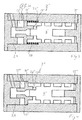
Fig. 1 shows a rock drilling machine including a device according to the invention in an axial section, -
Fig. 2 shows an enlarged section of a rear end portion of the rock drilling machine inFig. 1 , and -
Figs. 3 and 4 show, diagrammatically, two other variants of distribution valves. - In
Fig. 1 is thus shown an axial section of a rock drilling machine 1 including a machine housing 2, wherein an impact piston is axially movable to and fro inside a cylinder space comprising a working cylinder 4. The impact piston 3 performs impacts in an impact direction R against a shank adapter 5 in a per se known manner. - At the rear end region of the rock drilling machine 1 there is arranged a rear housing end wall 6, which closes the cylinder space 4. In the rear end region there is also positioned a
distribution valve 7 for distributing pressure fluid to the drive chambers of the rock drilling machine for driving the impact piston 3 to and fro. - In
Fig. 2 , said rear end region is shown in an enlarged scale, wherefrom can be seen that thedistribution valve 7 comprises a to and fromovable valve body 8 which is movable inside a valve bushing 9 between two end positions defined by abutments against a firstvalve end wall 10 and a second valve end wall 11, respectively. The valve bushing 9 limits avalve chamber 33 receiving thevalve body 8 and exhibiting usual bores comprising openings of channels being connected to thedistribution valve 7. The valve bushing is arranged to accurately define control edges for co-operation with corresponding control lands of thevalve body 8. - The
distribution valve 7 is arranged in a valve space 20 inside the housing 2 being closed by said rear housing end wall 6. - The first
valve end wall 10 is influenced by pressure in achamber 13, being permanently pressurized in operation of the rock drilling machine 1, saidchamber 13 co-operating with a piston portion 25 on the firstvalve end wall 10. Because of this pressurization, the firstvalve end wall 10 is pressed in a direction towards the second valve end wall 11. - The
valve end wall 10 exhibits anabutment surface 26 being directed against the second valve end wall 11, whereby saidabutment surface 26 will come into abutment against anabutment 12 at the end of the valve bushing 9. Hereby thevalve end wall 10 will be accurately positioned relative to the valve end wall 11 during pressurization of thechamber 13. - It should be understood that for correct positioning of the first
valve end wall 10 and thereby for obtaining an end position of thevalve body 8, there is hereby no longer any need of accurate machining with high tolerances of a bottom hole being formed having a surface directed in the direction of the second valve end wall 11, in what corresponds to the space receiving thedistribution valve 7, as is shown inFig. 2 . - Altogether is achieved through the invention that all elements adapted for co-operation with the
valve body 8, according to the above, can be effectively accurately positioned in respect of each other, since the valve bushing 9 can be machined in respect of control edges as well as at its (abutment) end(-s) in a relatively simple way. - In the position shown in
Fig. 2 , thevalve body 8 has a first abutment end 21 at a distance from afirst end abutment 17 on the firstvalve end wall 10 of the valve. Thevalve body 8 is in this position in abutment with a second abutment end 22 against asecond end abutment 34 on the second valve end wall 11. - An intermittently pressurized channel 14 is in this shown position pressurized such that a hydraulic pressure actuates an
end surface 15 of a centralend piston portion 23 of thevalve body 8, resulting in that this element takes the position shown inFig. 2 as is described above. - When the channel 14, because of the movement of the impact piston 3, instead is relieved from pressure (not shown), the
valve body 8 will be driven to the left in the Figure, such that the first abutment end 21 of thevalve body 8 will come to abutment against thefirst end abutment 17 on the firstvalve end wall 10. - This is achieved when a permanent pressurized
space 16 inside thevalve body 8 receives fluid under pressure transmitted through holes 27 in the wall of the valve body, such that the pressure in thisspace 16 acts against theend surface 24 of thespace 16 for driving thevalve body 8 to the left in the Figure. - The invention can also be realized by both the first and the second
valve end wall 10, 11 being movable such that both valve end walls can be pressed against abutments in directions towards each other for defining two defined end positions for thevalve body 8. - The
distribution valve 7 can also be made without a specific valve bushing 9. In that case e.g. an abutment corresponding to theabutment 12 can be arranged otherwise in the valve space 20, for example by an inserted locking sleeve comprising an abutment (corresponding to 12) of thevalve end wall 10. Alternatively a bore having an abutment can be machined from the end opposite to the opening of the bore shown inFig. 2 or in any other per se known way. - In
Fig. 2 thedistribution valve 7 is shown with its valve axis 18 parallel to the axis of the impact piston 3 and the work cylinder 4, being the axis of the percussion device of the rock drilling machine 1. This embodiment has the advantage that the rock drilling machine can be made slim and space-saving in its rear region. It also allows that said rear housing end wall 6 is common to the working cylinder and the distribution valve such that an otherwise necessary partition plane can be dispensed with. Through the construction with common axes and common rear housing end wall is achieved the advantage of lower machining costs and thereby reduced costs for the rock drilling machine. Further, the risk of moist and debris penetrating into the machine is reduced as well as the risk of failure because of unintentionally released screws. - A further advantage with having a pressurized valve end wall is that the valve body contacting this end wall will experience a softer abutment, since the pressurized valve end wall will be somewhat resilient and somewhat gives away in connection with the impact of the valve body. This reduces strain on the valve and thereby enhances function and increases working live. It is possible, within the scope of the invention, to make it possible to regulate this resilience by for example dimensioning a confined volume and a throttle in the conduit supplying hydraulic medium.
-
Fig. 3 shows a variant with a distribution valve, wherein a chamber 13' is pressurized with a variable pressure through a variable pressure source 30 against the action of aspring 28. By supplying pressure to this chamber 13', the valve end wall will thus be adjusted such that the higher the pressure the longer the valve end wall 10' will be set in the direction towards the second valve end wall 11'. This gives in certain particular operational cases a possibility to regulate the end position of the valve body and thereby the operation of the rock drilling machine. In this case "abutment" shall be interpreted such that the pressure is so high that the spring reaches the bottom, wherein a "fixed" abutment is obtained. For lower pressures, said adjustability is thus obtained. The channels of the distribution valve are not shown inFig. 3 for the sake of clarity. Channels for pressurized hydraulic fluid are indicated with interrupted lines. -
Fig. 4 shows a variant of a distribution valve similar to the one inFigs. 1 and 2 , but in this case (as inFig. 3 ) it is intended to illustrate a distribution valve without a valve bushing. "Valve space" is in this case "valve chamber". Achamber 13" is pressurized with a constant pressure. 12" indicates an abutment in the housing, which can be a machine housing of the rock drilling machine or a valve housing. Theabutment 12" is suitably produced through boring from the left, which is a direction opposite to the opening of the bore of the space for the distribution valve as seen in all embodiments. A lid for the further bore is indicated with 29.
Claims (13)
- Device for a hydraulic rock drilling machine (1) including a distribution valve (7,7',7") suitable for being arranged in connection with the rock drilling machine for controlling hydraulic flows to different parts of the rock drilling machine, wherein the distribution valve includes a valve body (8,8',8"), which is arranged movable to and fro in axial directions inside a valve chamber (33) and wherein the valve chamber is limited in axial direction by two valve end walls (10,11; 10',11'; 10",11"),
characterized in- that at least one of the valve end walls is movable in an axial direction against an abutment (12, 12") in such a way that it defines a fixed end position for the valve body,- that a pressing device (13,13',13") is arranged for pressing said at least one of the valve end walls in a direction of the second one of said valve end walls and against said abutment, and- that said pressing device (13,13',13") includes an end wall piston portion arranged on said at least one of the valve end walls and being received in a cylinder portion to be permanently pressurized in operation of the rock drilling machine in order to drive the valve end wall against said abutment during pressurizing. - Device according to claim 1, characterized in that the cylinder portion includes a connection to a hydraulic pressure source.
- Device according to claim 2, characterized in that the hydraulic pressure source is a system pressure source of the rock drilling machine (1).
- Device according to any one of the previous claims,
characterized in that the valve chamber (33) in a radial direction is limited by a valve bushing (9), which is formed with said abutment (12). - Device according to claim 4, characterized in that the valve bushing (9) on a side opposite to the one of the valve end walls (10) abuts the second one of the valve end walls (11).
- Device according to claims 4 or 5,
characterized in that the valve bushing (9) lies against a housing wall whereon abuts also one of the valve end walls (11). - Device according to any one of the previous claims,
characterized in that both valve end walls, a first as well as a second valve end wall, are movable axially against the respective abutment such that when, during pressurizing through a respective pressing device, they lie against these abutments so as to define both end positions of the valve body. - Device according to any one of the previous claims,
characterized in that an end position regulating device is arranged at at least one of the valve end walls (10) for positioning thereof axially in respect of said abutment for adjusting the end position (end positions) of the valve body. - Device according to claim 8, characterized in that the end position regulating device includes a chamber (13'), which is able to be pressurized with varying pressure (30) acting against any one from the group: a mechanical spring device, a hydraulic/pneumatic spring device, a spring device of synthetic elastic material, a spring device of rubber material.
- Hydraulic rock drilling machine (1) with a machine housing (2) which receives a working cylinder (4) with a to and fro movable impact piston (3), characterized in that the rock drilling machine includes a device according to any one of the claims 1 - 9.
- Hydraulic rock drilling machine according to claim 10,
characterized by said device with said distribution valve being received in the machine housing. - Hydraulic rock drilling machine according to claim 10 or 11, characterized in that the distribution valve has an axis (18), which is parallel to an axis (19) of the working cylinder (4).
- Hydraulic rock drilling machine according to claim 10, 11 or 12, characterized in that the rock drilling machine has a machine end wall (6) of the working cylinder (4), wherein said machining end wall also closes a space (20) for receiving the distribution valve (7,7',7").
Applications Claiming Priority (2)
| Application Number | Priority Date | Filing Date | Title |
|---|---|---|---|
| SE1251342A SE536903C2 (en) | 2012-11-28 | 2012-11-28 | Device at distribution valve for a rock drill and rock drill |
| PCT/SE2013/051376 WO2014084776A1 (en) | 2012-11-28 | 2013-11-22 | Device in a rock drilling machine and rock drilling machine |
Publications (3)
| Publication Number | Publication Date |
|---|---|
| EP2925491A1 EP2925491A1 (en) | 2015-10-07 |
| EP2925491A4 EP2925491A4 (en) | 2016-07-27 |
| EP2925491B1 true EP2925491B1 (en) | 2020-02-19 |
Family
ID=50828270
Family Applications (1)
| Application Number | Title | Priority Date | Filing Date |
|---|---|---|---|
| EP13859488.2A Active EP2925491B1 (en) | 2012-11-28 | 2013-11-22 | Device in a rock drilling machine and rock drilling machine |
Country Status (9)
| Country | Link |
|---|---|
| US (1) | US9937611B2 (en) |
| EP (1) | EP2925491B1 (en) |
| JP (1) | JP6304834B2 (en) |
| CN (1) | CN104822496B (en) |
| AU (1) | AU2013352659B2 (en) |
| CA (1) | CA2888570C (en) |
| SE (1) | SE536903C2 (en) |
| WO (1) | WO2014084776A1 (en) |
| ZA (1) | ZA201504599B (en) |
Families Citing this family (2)
| Publication number | Priority date | Publication date | Assignee | Title |
|---|---|---|---|---|
| SE538091C2 (en) * | 2014-03-18 | 2016-03-01 | Atlas Copco Rock Drills Ab | Distribution valve and rock drill |
| CN108869430B (en) * | 2018-09-18 | 2020-08-14 | 浙江智伦机电有限公司 | Small-size distribution valve |
Citations (1)
| Publication number | Priority date | Publication date | Assignee | Title |
|---|---|---|---|---|
| US2034122A (en) * | 1934-10-10 | 1936-03-17 | Ingersoll Rand Co | Rock drill |
Family Cites Families (20)
| Publication number | Priority date | Publication date | Assignee | Title |
|---|---|---|---|---|
| GB191219424A (en) * | 1912-08-24 | 1913-06-26 | George Rayner | Improvements in Valve Apparatus for Percussive Rock Drills and like Tools. |
| GB191319424A (en) | 1912-08-27 | 1913-11-06 | Emil Siebott | Improvements in Mortise Locks for Closets and like Doors. |
| GB191317236A (en) * | 1913-07-28 | 1914-08-28 | Arthur Boyd | An Improvement in the Propelling-mechanism of Bicycles and the like. |
| US1643560A (en) * | 1922-06-06 | 1927-09-27 | Denver Rock Drill Mfg Co | Fluid-actuated tool |
| GB250677A (en) * | 1925-01-16 | 1926-04-16 | John Leonard Holman | Improvements in or relating to distributing-valves for rock drills and like mechanisms |
| US2307866A (en) | 1941-09-20 | 1943-01-12 | Ingersoll Rand Co | Rock drill |
| US3240158A (en) | 1962-05-08 | 1966-03-15 | Robert W Brundage | Hydraulic pump or motor |
| US3818926A (en) * | 1973-04-11 | 1974-06-25 | D Wohlwend | Hydraulic valve and system |
| JPS5421807Y2 (en) * | 1973-07-26 | 1979-08-01 | ||
| JPS5716696Y2 (en) * | 1976-06-09 | 1982-04-07 | ||
| ES2044995T5 (en) | 1988-04-06 | 1996-10-16 | Nippon Pneumatic Mfg | HYDRAULIC IMPACT TOOL. |
| JPH078141Y2 (en) * | 1988-04-29 | 1995-03-01 | マツダ株式会社 | Hydraulic impact tool |
| CA2148394A1 (en) * | 1994-05-03 | 1995-11-04 | Alexander William Rowe | Starting and stopping of hydraulic reciprocating machines |
| FI104961B (en) | 1996-07-19 | 2000-05-15 | Sandvik Tamrock Oy | Hydraulic impact hammer |
| US6152715A (en) | 1998-01-30 | 2000-11-28 | Kaempe; Staffan I. | Pressure clamped hydraulic pump |
| FI115957B (en) * | 2001-11-07 | 2005-08-31 | Sandvik Tamrock Oy | Impact device with two pistons |
| FI116124B (en) * | 2004-02-23 | 2005-09-30 | Sandvik Tamrock Oy | Impact fluid driven impactor |
| SE527921C2 (en) * | 2004-10-20 | 2006-07-11 | Atlas Copco Rock Drills Ab | percussion |
| SE528743C2 (en) * | 2005-06-22 | 2007-02-06 | Atlas Copco Rock Drills Ab | Percussion for rock drill, procedure for effecting a reciprocating piston movement and rock drill |
| SE535757C2 (en) * | 2011-04-05 | 2012-12-11 | Atlas Copco Rock Drills Ab | Device and method for rock and concrete machining |
-
2012
- 2012-11-28 SE SE1251342A patent/SE536903C2/en unknown
-
2013
- 2013-11-22 EP EP13859488.2A patent/EP2925491B1/en active Active
- 2013-11-22 AU AU2013352659A patent/AU2013352659B2/en active Active
- 2013-11-22 US US14/435,209 patent/US9937611B2/en active Active
- 2013-11-22 CN CN201380061945.8A patent/CN104822496B/en active Active
- 2013-11-22 JP JP2015544035A patent/JP6304834B2/en active Active
- 2013-11-22 CA CA2888570A patent/CA2888570C/en active Active
- 2013-11-22 WO PCT/SE2013/051376 patent/WO2014084776A1/en not_active Ceased
-
2015
- 2015-06-25 ZA ZA2015/04599A patent/ZA201504599B/en unknown
Patent Citations (1)
| Publication number | Priority date | Publication date | Assignee | Title |
|---|---|---|---|---|
| US2034122A (en) * | 1934-10-10 | 1936-03-17 | Ingersoll Rand Co | Rock drill |
Also Published As
| Publication number | Publication date |
|---|---|
| CN104822496B (en) | 2016-08-24 |
| SE536903C2 (en) | 2014-10-21 |
| CN104822496A (en) | 2015-08-05 |
| AU2013352659B2 (en) | 2017-07-06 |
| AU2013352659A1 (en) | 2015-06-18 |
| ZA201504599B (en) | 2016-11-30 |
| CA2888570C (en) | 2021-01-19 |
| CA2888570A1 (en) | 2014-06-05 |
| WO2014084776A1 (en) | 2014-06-05 |
| JP2015535494A (en) | 2015-12-14 |
| EP2925491A4 (en) | 2016-07-27 |
| EP2925491A1 (en) | 2015-10-07 |
| US20150273677A1 (en) | 2015-10-01 |
| JP6304834B2 (en) | 2018-04-04 |
| SE1251342A1 (en) | 2014-05-29 |
| US9937611B2 (en) | 2018-04-10 |
Similar Documents
| Publication | Publication Date | Title |
|---|---|---|
| CN101500762B (en) | Percussion device, drilling machine including such a percussion device and method for controlling such a percussion device | |
| FI123187B (en) | Rock-breaker impactor, method for controlling impactor | |
| US9937611B2 (en) | Device in a rock drilling machine and rock drilling machine | |
| WO2007097677A1 (en) | Percussion device and rock drilling machine including such a percussion device | |
| KR20200120671A (en) | Rotary impact hydraulic drill with control chamber permanently connected to the low pressure accumulator | |
| EP2099999B1 (en) | Rock drilling equipment and a method in association with same | |
| US8997625B2 (en) | Hydraulic feed-rate control apparatus | |
| FI96189C (en) | Adjustable frequency control in the impact machine | |
| ZA202403636B (en) | Valve cylinder, impact device and method | |
| US7644646B1 (en) | Three position servo system to control the displacement of a hydraulic motor | |
| US10890267B2 (en) | Pressure-limiting valve | |
| KR102219022B1 (en) | Anti-vibration structure for sensor of hydraulic breaker | |
| WO2015142259A1 (en) | Distribution valve and rock drilling machine | |
| US8739896B2 (en) | Percussion device | |
| SU840330A1 (en) | Percussion mechanism for drilling machines | |
| US7896100B2 (en) | Valve device for a percussion device and a percussion device for a rock drilling machine | |
| SU1016499A1 (en) | Hydraulic percussive mechanism | |
| SU1495545A1 (en) | Hydraulic vibrator | |
| JP4181969B2 (en) | Control valve | |
| KR20090038689A (en) | Sliding gate valve assembly | |
| JP2020075311A (en) | Torque control wrench | |
| GB1585117A (en) | Percussive tools particularly casing constructions thereof |
Legal Events
| Date | Code | Title | Description |
|---|---|---|---|
| PUAI | Public reference made under article 153(3) epc to a published international application that has entered the european phase |
Free format text: ORIGINAL CODE: 0009012 |
|
| 17P | Request for examination filed |
Effective date: 20150522 |
|
| AK | Designated contracting states |
Kind code of ref document: A1 Designated state(s): AL AT BE BG CH CY CZ DE DK EE ES FI FR GB GR HR HU IE IS IT LI LT LU LV MC MK MT NL NO PL PT RO RS SE SI SK SM TR |
|
| AX | Request for extension of the european patent |
Extension state: BA ME |
|
| DAX | Request for extension of the european patent (deleted) | ||
| RA4 | Supplementary search report drawn up and despatched (corrected) |
Effective date: 20160627 |
|
| RIC1 | Information provided on ipc code assigned before grant |
Ipc: F16K 27/00 20060101ALI20160621BHEP Ipc: E21B 1/26 20060101ALI20160621BHEP Ipc: B25D 9/14 20060101AFI20160621BHEP |
|
| RAP1 | Party data changed (applicant data changed or rights of an application transferred) |
Owner name: EPIROC ROCK DRILLS AKTIEBOLAG |
|
| GRAP | Despatch of communication of intention to grant a patent |
Free format text: ORIGINAL CODE: EPIDOSNIGR1 |
|
| STAA | Information on the status of an ep patent application or granted ep patent |
Free format text: STATUS: GRANT OF PATENT IS INTENDED |
|
| INTG | Intention to grant announced |
Effective date: 20190920 |
|
| GRAS | Grant fee paid |
Free format text: ORIGINAL CODE: EPIDOSNIGR3 |
|
| GRAA | (expected) grant |
Free format text: ORIGINAL CODE: 0009210 |
|
| STAA | Information on the status of an ep patent application or granted ep patent |
Free format text: STATUS: THE PATENT HAS BEEN GRANTED |
|
| AK | Designated contracting states |
Kind code of ref document: B1 Designated state(s): AL AT BE BG CH CY CZ DE DK EE ES FI FR GB GR HR HU IE IS IT LI LT LU LV MC MK MT NL NO PL PT RO RS SE SI SK SM TR |
|
| REG | Reference to a national code |
Ref country code: CH Ref legal event code: EP |
|
| REG | Reference to a national code |
Ref country code: DE Ref legal event code: R096 Ref document number: 602013066040 Country of ref document: DE |
|
| REG | Reference to a national code |
Ref country code: AT Ref legal event code: REF Ref document number: 1234398 Country of ref document: AT Kind code of ref document: T Effective date: 20200315 |
|
| REG | Reference to a national code |
Ref country code: FI Ref legal event code: FGE |
|
| REG | Reference to a national code |
Ref country code: IE Ref legal event code: FG4D |
|
| REG | Reference to a national code |
Ref country code: NL Ref legal event code: MP Effective date: 20200219 |
|
| PG25 | Lapsed in a contracting state [announced via postgrant information from national office to epo] |
Ref country code: RS Free format text: LAPSE BECAUSE OF FAILURE TO SUBMIT A TRANSLATION OF THE DESCRIPTION OR TO PAY THE FEE WITHIN THE PRESCRIBED TIME-LIMIT Effective date: 20200219 Ref country code: NO Free format text: LAPSE BECAUSE OF FAILURE TO SUBMIT A TRANSLATION OF THE DESCRIPTION OR TO PAY THE FEE WITHIN THE PRESCRIBED TIME-LIMIT Effective date: 20200519 |
|
| REG | Reference to a national code |
Ref country code: LT Ref legal event code: MG4D |
|
| PG25 | Lapsed in a contracting state [announced via postgrant information from national office to epo] |
Ref country code: HR Free format text: LAPSE BECAUSE OF FAILURE TO SUBMIT A TRANSLATION OF THE DESCRIPTION OR TO PAY THE FEE WITHIN THE PRESCRIBED TIME-LIMIT Effective date: 20200219 Ref country code: IS Free format text: LAPSE BECAUSE OF FAILURE TO SUBMIT A TRANSLATION OF THE DESCRIPTION OR TO PAY THE FEE WITHIN THE PRESCRIBED TIME-LIMIT Effective date: 20200619 Ref country code: SE Free format text: LAPSE BECAUSE OF FAILURE TO SUBMIT A TRANSLATION OF THE DESCRIPTION OR TO PAY THE FEE WITHIN THE PRESCRIBED TIME-LIMIT Effective date: 20200219 Ref country code: LV Free format text: LAPSE BECAUSE OF FAILURE TO SUBMIT A TRANSLATION OF THE DESCRIPTION OR TO PAY THE FEE WITHIN THE PRESCRIBED TIME-LIMIT Effective date: 20200219 Ref country code: BG Free format text: LAPSE BECAUSE OF FAILURE TO SUBMIT A TRANSLATION OF THE DESCRIPTION OR TO PAY THE FEE WITHIN THE PRESCRIBED TIME-LIMIT Effective date: 20200519 Ref country code: GR Free format text: LAPSE BECAUSE OF FAILURE TO SUBMIT A TRANSLATION OF THE DESCRIPTION OR TO PAY THE FEE WITHIN THE PRESCRIBED TIME-LIMIT Effective date: 20200520 |
|
| PG25 | Lapsed in a contracting state [announced via postgrant information from national office to epo] |
Ref country code: NL Free format text: LAPSE BECAUSE OF FAILURE TO SUBMIT A TRANSLATION OF THE DESCRIPTION OR TO PAY THE FEE WITHIN THE PRESCRIBED TIME-LIMIT Effective date: 20200219 |
|
| PG25 | Lapsed in a contracting state [announced via postgrant information from national office to epo] |
Ref country code: PT Free format text: LAPSE BECAUSE OF FAILURE TO SUBMIT A TRANSLATION OF THE DESCRIPTION OR TO PAY THE FEE WITHIN THE PRESCRIBED TIME-LIMIT Effective date: 20200712 Ref country code: RO Free format text: LAPSE BECAUSE OF FAILURE TO SUBMIT A TRANSLATION OF THE DESCRIPTION OR TO PAY THE FEE WITHIN THE PRESCRIBED TIME-LIMIT Effective date: 20200219 Ref country code: SK Free format text: LAPSE BECAUSE OF FAILURE TO SUBMIT A TRANSLATION OF THE DESCRIPTION OR TO PAY THE FEE WITHIN THE PRESCRIBED TIME-LIMIT Effective date: 20200219 Ref country code: LT Free format text: LAPSE BECAUSE OF FAILURE TO SUBMIT A TRANSLATION OF THE DESCRIPTION OR TO PAY THE FEE WITHIN THE PRESCRIBED TIME-LIMIT Effective date: 20200219 Ref country code: CZ Free format text: LAPSE BECAUSE OF FAILURE TO SUBMIT A TRANSLATION OF THE DESCRIPTION OR TO PAY THE FEE WITHIN THE PRESCRIBED TIME-LIMIT Effective date: 20200219 Ref country code: ES Free format text: LAPSE BECAUSE OF FAILURE TO SUBMIT A TRANSLATION OF THE DESCRIPTION OR TO PAY THE FEE WITHIN THE PRESCRIBED TIME-LIMIT Effective date: 20200219 Ref country code: EE Free format text: LAPSE BECAUSE OF FAILURE TO SUBMIT A TRANSLATION OF THE DESCRIPTION OR TO PAY THE FEE WITHIN THE PRESCRIBED TIME-LIMIT Effective date: 20200219 Ref country code: SM Free format text: LAPSE BECAUSE OF FAILURE TO SUBMIT A TRANSLATION OF THE DESCRIPTION OR TO PAY THE FEE WITHIN THE PRESCRIBED TIME-LIMIT Effective date: 20200219 Ref country code: DK Free format text: LAPSE BECAUSE OF FAILURE TO SUBMIT A TRANSLATION OF THE DESCRIPTION OR TO PAY THE FEE WITHIN THE PRESCRIBED TIME-LIMIT Effective date: 20200219 |
|
| REG | Reference to a national code |
Ref country code: AT Ref legal event code: MK05 Ref document number: 1234398 Country of ref document: AT Kind code of ref document: T Effective date: 20200219 |
|
| REG | Reference to a national code |
Ref country code: DE Ref legal event code: R097 Ref document number: 602013066040 Country of ref document: DE |
|
| PLBE | No opposition filed within time limit |
Free format text: ORIGINAL CODE: 0009261 |
|
| STAA | Information on the status of an ep patent application or granted ep patent |
Free format text: STATUS: NO OPPOSITION FILED WITHIN TIME LIMIT |
|
| 26N | No opposition filed |
Effective date: 20201120 |
|
| PG25 | Lapsed in a contracting state [announced via postgrant information from national office to epo] |
Ref country code: AT Free format text: LAPSE BECAUSE OF FAILURE TO SUBMIT A TRANSLATION OF THE DESCRIPTION OR TO PAY THE FEE WITHIN THE PRESCRIBED TIME-LIMIT Effective date: 20200219 Ref country code: IT Free format text: LAPSE BECAUSE OF FAILURE TO SUBMIT A TRANSLATION OF THE DESCRIPTION OR TO PAY THE FEE WITHIN THE PRESCRIBED TIME-LIMIT Effective date: 20200219 |
|
| PG25 | Lapsed in a contracting state [announced via postgrant information from national office to epo] |
Ref country code: SI Free format text: LAPSE BECAUSE OF FAILURE TO SUBMIT A TRANSLATION OF THE DESCRIPTION OR TO PAY THE FEE WITHIN THE PRESCRIBED TIME-LIMIT Effective date: 20200219 Ref country code: PL Free format text: LAPSE BECAUSE OF FAILURE TO SUBMIT A TRANSLATION OF THE DESCRIPTION OR TO PAY THE FEE WITHIN THE PRESCRIBED TIME-LIMIT Effective date: 20200219 |
|
| REG | Reference to a national code |
Ref country code: DE Ref legal event code: R119 Ref document number: 602013066040 Country of ref document: DE |
|
| PG25 | Lapsed in a contracting state [announced via postgrant information from national office to epo] |
Ref country code: MC Free format text: LAPSE BECAUSE OF FAILURE TO SUBMIT A TRANSLATION OF THE DESCRIPTION OR TO PAY THE FEE WITHIN THE PRESCRIBED TIME-LIMIT Effective date: 20200219 |
|
| REG | Reference to a national code |
Ref country code: CH Ref legal event code: PL |
|
| GBPC | Gb: european patent ceased through non-payment of renewal fee |
Effective date: 20201122 |
|
| PG25 | Lapsed in a contracting state [announced via postgrant information from national office to epo] |
Ref country code: LU Free format text: LAPSE BECAUSE OF NON-PAYMENT OF DUE FEES Effective date: 20201122 |
|
| REG | Reference to a national code |
Ref country code: BE Ref legal event code: MM Effective date: 20201130 |
|
| PG25 | Lapsed in a contracting state [announced via postgrant information from national office to epo] |
Ref country code: CH Free format text: LAPSE BECAUSE OF NON-PAYMENT OF DUE FEES Effective date: 20201130 Ref country code: LI Free format text: LAPSE BECAUSE OF NON-PAYMENT OF DUE FEES Effective date: 20201130 |
|
| PG25 | Lapsed in a contracting state [announced via postgrant information from national office to epo] |
Ref country code: IE Free format text: LAPSE BECAUSE OF NON-PAYMENT OF DUE FEES Effective date: 20201122 |
|
| PG25 | Lapsed in a contracting state [announced via postgrant information from national office to epo] |
Ref country code: GB Free format text: LAPSE BECAUSE OF NON-PAYMENT OF DUE FEES Effective date: 20201122 Ref country code: DE Free format text: LAPSE BECAUSE OF NON-PAYMENT OF DUE FEES Effective date: 20210601 |
|
| PG25 | Lapsed in a contracting state [announced via postgrant information from national office to epo] |
Ref country code: MT Free format text: LAPSE BECAUSE OF FAILURE TO SUBMIT A TRANSLATION OF THE DESCRIPTION OR TO PAY THE FEE WITHIN THE PRESCRIBED TIME-LIMIT Effective date: 20200219 Ref country code: CY Free format text: LAPSE BECAUSE OF FAILURE TO SUBMIT A TRANSLATION OF THE DESCRIPTION OR TO PAY THE FEE WITHIN THE PRESCRIBED TIME-LIMIT Effective date: 20200219 |
|
| PG25 | Lapsed in a contracting state [announced via postgrant information from national office to epo] |
Ref country code: MK Free format text: LAPSE BECAUSE OF FAILURE TO SUBMIT A TRANSLATION OF THE DESCRIPTION OR TO PAY THE FEE WITHIN THE PRESCRIBED TIME-LIMIT Effective date: 20200219 Ref country code: AL Free format text: LAPSE BECAUSE OF FAILURE TO SUBMIT A TRANSLATION OF THE DESCRIPTION OR TO PAY THE FEE WITHIN THE PRESCRIBED TIME-LIMIT Effective date: 20200219 |
|
| PG25 | Lapsed in a contracting state [announced via postgrant information from national office to epo] |
Ref country code: BE Free format text: LAPSE BECAUSE OF NON-PAYMENT OF DUE FEES Effective date: 20201130 |
|
| PGFP | Annual fee paid to national office [announced via postgrant information from national office to epo] |
Ref country code: FI Payment date: 20251022 Year of fee payment: 13 |
|
| PGFP | Annual fee paid to national office [announced via postgrant information from national office to epo] |
Ref country code: FR Payment date: 20251022 Year of fee payment: 13 |
|
| PGFP | Annual fee paid to national office [announced via postgrant information from national office to epo] |
Ref country code: TR Payment date: 20251031 Year of fee payment: 13 |