EP2925420B1 - Method for redundant sterile filtration - Google Patents
Method for redundant sterile filtration Download PDFInfo
- Publication number
- EP2925420B1 EP2925420B1 EP13859871.9A EP13859871A EP2925420B1 EP 2925420 B1 EP2925420 B1 EP 2925420B1 EP 13859871 A EP13859871 A EP 13859871A EP 2925420 B1 EP2925420 B1 EP 2925420B1
- Authority
- EP
- European Patent Office
- Prior art keywords
- filter
- sterilizing
- fluid
- membrane
- air
- Prior art date
- Legal status (The legal status is an assumption and is not a legal conclusion. Google has not performed a legal analysis and makes no representation as to the accuracy of the status listed.)
- Active
Links
Images


Classifications
-
- B—PERFORMING OPERATIONS; TRANSPORTING
- B01—PHYSICAL OR CHEMICAL PROCESSES OR APPARATUS IN GENERAL
- B01D—SEPARATION
- B01D19/00—Degasification of liquids
- B01D19/0031—Degasification of liquids by filtration
-
- A—HUMAN NECESSITIES
- A61—MEDICAL OR VETERINARY SCIENCE; HYGIENE
- A61L—METHODS OR APPARATUS FOR STERILISING MATERIALS OR OBJECTS IN GENERAL; DISINFECTION, STERILISATION OR DEODORISATION OF AIR; CHEMICAL ASPECTS OF BANDAGES, DRESSINGS, ABSORBENT PADS OR SURGICAL ARTICLES; MATERIALS FOR BANDAGES, DRESSINGS, ABSORBENT PADS OR SURGICAL ARTICLES
- A61L2/00—Methods or apparatus for disinfecting or sterilising materials or objects other than foodstuffs or contact lenses; Accessories therefor
- A61L2/0005—Methods or apparatus for disinfecting or sterilising materials or objects other than foodstuffs or contact lenses; Accessories therefor for pharmaceuticals, biologicals or living parts
- A61L2/0011—Methods or apparatus for disinfecting or sterilising materials or objects other than foodstuffs or contact lenses; Accessories therefor for pharmaceuticals, biologicals or living parts using physical methods
- A61L2/0017—Filtration
-
- B—PERFORMING OPERATIONS; TRANSPORTING
- B01—PHYSICAL OR CHEMICAL PROCESSES OR APPARATUS IN GENERAL
- B01D—SEPARATION
- B01D61/00—Processes of separation using semi-permeable membranes, e.g. dialysis, osmosis or ultrafiltration; Apparatus, accessories or auxiliary operations specially adapted therefor
- B01D61/14—Ultrafiltration; Microfiltration
- B01D61/18—Apparatus therefor
-
- B—PERFORMING OPERATIONS; TRANSPORTING
- B01—PHYSICAL OR CHEMICAL PROCESSES OR APPARATUS IN GENERAL
- B01D—SEPARATION
- B01D2313/00—Details relating to membrane modules or apparatus
- B01D2313/16—Specific vents
-
- B—PERFORMING OPERATIONS; TRANSPORTING
- B01—PHYSICAL OR CHEMICAL PROCESSES OR APPARATUS IN GENERAL
- B01D—SEPARATION
- B01D2313/00—Details relating to membrane modules or apparatus
- B01D2313/44—Cartridge types
-
- B—PERFORMING OPERATIONS; TRANSPORTING
- B01—PHYSICAL OR CHEMICAL PROCESSES OR APPARATUS IN GENERAL
- B01D—SEPARATION
- B01D2315/00—Details relating to the membrane module operation
- B01D2315/08—Fully permeating type; Dead-end filtration
-
- B—PERFORMING OPERATIONS; TRANSPORTING
- B01—PHYSICAL OR CHEMICAL PROCESSES OR APPARATUS IN GENERAL
- B01D—SEPARATION
- B01D2317/00—Membrane module arrangements within a plant or an apparatus
- B01D2317/02—Elements in series
- B01D2317/025—Permeate series
-
- B—PERFORMING OPERATIONS; TRANSPORTING
- B01—PHYSICAL OR CHEMICAL PROCESSES OR APPARATUS IN GENERAL
- B01D—SEPARATION
- B01D2317/00—Membrane module arrangements within a plant or an apparatus
- B01D2317/06—Use of membrane modules of the same kind
-
- B—PERFORMING OPERATIONS; TRANSPORTING
- B01—PHYSICAL OR CHEMICAL PROCESSES OR APPARATUS IN GENERAL
- B01D—SEPARATION
- B01D2319/00—Membrane assemblies within one housing
- B01D2319/02—Elements in series
-
- B—PERFORMING OPERATIONS; TRANSPORTING
- B01—PHYSICAL OR CHEMICAL PROCESSES OR APPARATUS IN GENERAL
- B01D—SEPARATION
- B01D2325/00—Details relating to properties of membranes
- B01D2325/36—Hydrophilic membranes
-
- B—PERFORMING OPERATIONS; TRANSPORTING
- B01—PHYSICAL OR CHEMICAL PROCESSES OR APPARATUS IN GENERAL
- B01D—SEPARATION
- B01D2325/00—Details relating to properties of membranes
- B01D2325/38—Hydrophobic membranes
-
- B—PERFORMING OPERATIONS; TRANSPORTING
- B01—PHYSICAL OR CHEMICAL PROCESSES OR APPARATUS IN GENERAL
- B01D—SEPARATION
- B01D63/00—Apparatus in general for separation processes using semi-permeable membranes
- B01D63/08—Flat membrane modules
- B01D63/082—Flat membrane modules comprising a stack of flat membranes
- B01D63/084—Flat membrane modules comprising a stack of flat membranes at least one flow duct intersecting the membranes
Definitions
- the second sterilizing-grade filter is incorporated in line, usually upstream but possibly downstream, to provide additional assurance of sterilizing filtration. This can be particularly important for batches that cannot be reworked in the event of a sterilizing filter integrity failure, resulting in complete loss of the batch often at consideration expense.
- hydrophilic filters will not allow air passage once wet. Venting air from the capsules requires either a separate sterile vent filter or more commonly a closed, sterile waste reservoir to vent into. Pre-use integrity testing of the capsules requires an intermediate drain filter between them to allow downstream flow. Drying the cartridges before introducing product requires exceeding the bubble point pressure of the membrane with compressed air for approximately 20 minutes. When two capsules are attached in series, it is typically difficult to execute this drying step due to the additive pressure drop across both devises and the overall working pressure rating of the housings. For this reason, the capsules are typically dried separately through the intermediate drain filter and an additional air inlet filter placed before the second sterile filter.
- US 2009/0182263 A1 discloses a filtration system for the preparation of fluids for medical applications. It comprises a hydrophobic filter in an air vent and a hydrophilic filter in an air filter in the outlet.
- WO 2012/013256 A1 discloses a device for degassing aqueous media.
- a hydrophobic membrane is part of a hydrophobic degassing filter and prevents the passage of aqueous media. Accordingly, it does not filter the fluid in the process stream that yields the product.
- US 2002/0096467 A1 discloses a chemical process system with a multi-functional barrier filter.
- the barrier filter is a separate filter that does not provide the function of a process filter.
- the present invention relates to a method of filtering a liquid raw material in a process stream to yield product and is defined in claim 1.
- Advantageous versions of the invention follow from the dependent claims.
- the problems of the prior art have been overcome by the embodiments disclosed herein, which provide a redundant filtration system that includes at least one barrier filter as a process filter, the barrier filter having both hydrophilic and hydrophobic paths, allowing both fluid and gas permeability.
- the barrier filter By substituting one or both of the sterile process filters used in a conventional single use redundant filter design with a barrier filter, the need for vents is eliminated, as is the intermediate drain filter.
- the device also can be dried in series.
- the filtration system includes a network of conduits and receptacles, the network receiving liquid raw and/or starting material at one end, conducting it through the process stream defined thereby, and producing the desired liquid product at another end.
- the network is provided with one or more inputs for introducing liquid raw material into the fluid process stream, and one or more output ports for discharging fluid out of the fluid process stream.
- the network is preferably an essentially closed network, and also, preferably sterile and/or aseptic.
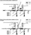
- FIG. 1 there is shown schematically a conventional single use redundant filter design.
- the system includes the requisite network of conduits, including one or more inlets (e.g., for gas and water), one or more outlets (e.g., a drain and a product outlet), and appropriate valving, defining a fluid process stream designed to receive starting material at an inlet, conduct it through the process stream including a filtration train, and producing the desired product to be discharged at an outlet.
- the filtration train includes a first sterile process filter F-1, and a second sterile process filter F-2 in series with and downstream of the first sterile process filter F-1.
- An intermediate drain filter D-1 is positioned between filters F-1 and F-2, and a primary drain filter D-2 is positioned downstream of filter F-2 as shown.
- a process filter or membrane is that employed in the system for the purpose of conducting the system's manufacturing process to yield product.
- the manufacturing process will either not yield the desired product or otherwise yield a markedly different product (i.e., in respect of purity, concentration, and the like) in the absence of the process filter or membrane component.
- the process filter or membrane component is positioned within the fluid process stream and is capable of filtering the aforementioned liquid raw material as it passes therethrough.
- the term "process filter” as used herein is therefore different from a drain filter, which is not used to filter product, but rather is in the network to enable integrity testing and maintain system sterility at the drain outlet.
- FIG. 2 The flushing of the system of FIG. 1 is shown schematically in FIG. 2
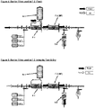
- FIG. 3 An intermediate air filter A-1 is positioned between the first and second process filters, and is provided to integrity test or dry F-2
- first and second closed sterile waste reservoirs or vent bags R-1 and R-2 are provided in fluid communication with the first and second process filters, respectively, to receive the respective vented air from filters F-1 and F-2.
- Downstream flow during integrity testing and drying of F-1 is enabled by the use of the intermediate drain filter D-1 positioned between the process filters F-1 and F-2. Integrity testing and drying of F-2 is performed with air administered through A-1 with downstream flow of F-2 enabled by the use of the drain filter D-2.
- the need for the intermediate drain filter D-1, the intermediate air filter A-1, and the vent bag on the housing containing the barrier filter can be eliminated.
- the second, downstream process filter is a barrier filter BF.
- a barrier filter enables the elimination of the vent bag R-2 on the second downstream filter. This is because the barrier filter contains hydrophilic and hydrophobic membranes, which allows any air upstream of F-2 to pass downstream without needing to be vented.
- the entire system can be dried in series as a single operation, which eliminates intermediate air filter A-1 and intermediate drain filter D-1.
- the barrier filter allows gas and liquid flow, which means air flow through the system can be accomplished by exceeding the bubble point of F-1 ( ⁇ 50 psi (3.45 bar)).
- This is in comparison to the current state of the art, which would require an air inlet pressure which exceeds the sum of the bubble point pressures for F-1 and F-2 (>100 psi (6.9 bar)).
- the pressure required to accomplish this typically exceeds the maximum working pressure rating of the intermediate components and is therefore not practical.
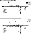
- FIGS. 6 and 7 illustrate an embodiment where the upstream process filter is a barrier filter BF.
- the upstream process filter is a barrier filter BF.
- This also enables the elimination of the intermediate air filter, the intermediate drain filter, and enables the elimination of the vent bag on the upstream filter for the same reasons as described above: a) Venting of the F-1 filter is no longer necessary since any air present will flow downstream b) F-1 and F-2 can be dried in series due to the barrier filter's ability to allow gas flow when wet.
- pre-use integrity testing can be carried out on the downstream filter F-2 ( FIG. 7 ), which is preferred since it is closer to the final point of use (a filling machine).
- FIGS. 8 and 9 illustrate a further embodiment where both process filters in series are barrier filters BF. Since barrier filters can pass air downstream, the filter housing does not require vents. This, combined with the ease with which they can be dried, results in the elimination of all venting operations and necessary vent bags along with the intermediate drain and air filters. As a result, minimal operator manipulation is required other than redirection of flow from the drain to the filling machine upon completion of the drying operation.
- pre-use integrity testing of the filters is not possible in this embodiment, since barrier filters only can be tested after wetting with isopropyl alcohol, which is not practical since verification of the complete removal of the alcohol would be required prior to introducing the product into the system. However, post-use testing can be readily performed.
- FIG. 10 illustrates a simplified system with a unique vertical configuration of the filtration stages with F-1 configured as a barrier filter and F-2 a typical sterilizing grade hydrophilic filter. This is functionally equivalent to the embodiment shown in Figures 6 & 7 with the exception of the vent path for F-2.
- the air entrapped within process filter F-2 is allowed to rise through the housing and backflow through the hydrophobic portion of F-1. This is unique in that the air is passed back to the upstream side of filter F-1, which is considered to be the non-sterile side of the device.
- a hydrophobic membrane may be integrated into the vent ( FIG. 11 ) such that it can vent directly to atmosphere without requiring a vent bag. After a hydrophilic membrane is wet, it will not allow air to pass through. When first introducing liquid to the system, or if a user chooses to introduce product after flushing with water but not drying, it is necessary to vent the air from the system. Historically this has been accomplished with vent ports/valves which allow the air to escape the filter housing to the environment. This is considered unacceptable because opening the vent to atmosphere could breach sterility, and the final fill/filter application is conducted in a highly controlled area and allowing fluid to escape the filter would be considered a contamination of the environment. If a hydrophobic membrane is placed in line with the vent, it will maintain sterility and prevent liquid from escaping.
- the configuration shown in FIG. 10 eliminates the need, during wetting, to isolate the air inlet line between F-1 and F-2, to remove the clamp normally present between F-1 and F-2 and isolate F-3 from F-2, to fill F-2 while venting out the top of F-2 and to close the vent.
- This is enabled by the elimination of A-1 and D-1, along with configuring F-1 and F-2 as a single housing which eliminates the need for all but a single vent.
- wetting simply involves connecting a water supply to F-1 and fill the housing, venting out the top, closing the vent, and unclamping F-3 and flowing to drain.
- the configuration shown in FIG. 10 also eliminates the need, during draining, to connect an air supply to the vent filter between F-1 and F-2 to drain F-2 since the air upstream of F-1 can freely pass through the barrier filter to F-2. Thus, draining simply requires connecting an air supply to F-1 upstream of F-2 to drain F-1.
- the configuration shown in FIG. 10 also eliminates the need, during integrity testing, to isolate F-1 from F-2 and the vent filter, to attach an integrity tester to the vent filter and test F-2, and to isolate F-2 from F-1 and the vent filter since the barrier filter in F-1 is transparent to a typical bubble point or diffusion integrity tester.
- integrity testing simply requires attaching the integrity tester to F-1 and testing F-2.
- the configuration shown in FIG. 10 also eliminates the need, during drying, to isolate F-1 from F-2 and the vent filter, and to attach an air supply to the vent filter and exhaust F-2 through F-3. Thus, drying simply requires attaching an air supply to F-1 and exhausting through the vent filter (F-3) .
- FIG. 11 shows a configuration wherein two devices are combined into one, and an integrated hydrophobic vent is added to the top of the filter chamber of F-1 to eliminate the vent bag.
- the fluid enters the inlet and flows through a hydrophilic process membrane F-1 in the first stage, then passes to the upstream side of the second stage where it is filtered through the hydrophilic portion of the process membrane F-2 (the barrier filter).
- the first chamber or stage (in the direction of flow) includes a hydrophobic vent membrane.
- the second chamber or stage includes a hydrophobic portion of the membrane as shown.
- the top of the barrier filter is open (the end cap has hole in center) with a piece of hydrophobic membrane placed over it. As flow is introduced and fluid passes through the hydrophilic portion, there is a pressure drop across the filter.
- FIG. 12 shows a configuration wherein two devices are combined into one and an integrated hydrophobic vent with a shutoff valve is added to the top of the filter chamber of F-2 to eliminate the vent bag.
- the fluid enters the inlet and flows through a hydrophilic portion of the process membrane F-1 in the first stage, then passes to the upstream side of the second stage where it is filtered through the hydrophilic process membrane F-2.
- the first chamber or stage (in the direction of flow) includes a hydrophobic portion of the membrane as shown.
- the second chamber or stage includes a hydrophobic vent membrane.
- FIG. 13 shows a configuration with two typical hydrophilic filters and a hydrophobic vent at the top of both filter chambers. These vents are then connected together to form a single vent outlet for ease of use.
- the fluid enters the inlet and flows through a hydrophilic process membrane F-1 in the first stage, then passes to the upstream side of the second stage where it is filtered through the hydrophilic process membrane F-2.
- Each chamber or stage includes a hydrophobic vent membrane. This allows the elimination of R-1 and R-2 since contamination cannot pass the sterilizing grade hydrophobic membrane into the system nor can product escape the system and contaminate the surrounding environment. Additionally, an air bypass is created by connecting the vents of F-1 and F-2. This allows F-1 and F-2 to by dried in series which is not practical in the conventional embodiment shown in FIG. 1 due to the additive pressures necessary to exceed the bubble point of both filters.
- Each of the chambers or stages in the embodiments of FIGS. 10-13 can be a perforated outer sleeve, have folds of membrane within, and a perforated central core.
- the flow path is from the outside to the inner perforated core and then out through the center of the device.
- the outlet of F-1 center of filter
- the membrane of F-2 flows into the inlet side of the F-2 chamber. It then flows through the membrane of F-2, down the center core of F-2, and to the outlet of the device.
- the internal pressure rises above atmospheric.
- the wetted hydrophilic membrane will not allow air to pass through it. Any air within the filter chamber then rises to the top and passes through the hydrophobic membrane which will not allow aqueous fluid to pass. It is then vented to atmosphere.
- These device housings could be constructed by any of the typical processes known to those skilled in the art. For example, more than one component joined by fasteners and elastomeric seals, parent material welding or bonding, or use of an intermediate material to adhere the components together can be used. Suitable components included molded thermoplastic, but could readily be made by machining or any other form of production suitable for the material chosen. The typical materials of construction would be anything which is currently accepted for use in the pharmaceutical industry, including polypropylene, polyethylene, PVDF, polysulfone, polycarbonate, or PTFE. Additionally, stainless steel also can be used, which is accepted as an industry standard. The filtration devices shown within these housings could be produced by any of the typical methods used in production today. This includes pleated membranes assembled with thermoplastic endcaps, thermoplastic disks with attached membrane, spirals or any other method of production.
- the filtration devices and housing could be integrated by any of the assembly techniques noted as possible for assembling the housing itself.
- the barrier filter comprises a filter comprising, within a common enclosure, several hydrophobic and hydrophilic membranes, the common enclosure having a fluid inlet, a fluid outlet, and a fluid path therebetween, all filter membranes being located within the fluid path.
- the filter can be configured as a so-called process scale cartridge or capsule filter device provided with wrapped, wound, or stacked hydrophobic and hydrophilic membrane material.
- the common enclosure of the filter can be structured in various formats and dimensions, employing a variety of materials. Common formats include, but are not limited to, boxlike cassettes, disks, and long or squat cylinders. It is preferred that the common enclosure be structured such that, but for the enclosure's inlet and outlet, the internal volume contained thereby is essentially "closed". The enclosure's inlet and outlet, in combination with the filter's internal structure, will determine the process stream through which fluid is conducted through the filter.
- the filter membrane component of the filters can be positioned within the process stream in several arrangements. For example, the membrane components can be positioned tangentially or orthogonally along the process stream. The membrane component is configured as a stack of individual membrane disks.
- the barrier filter can be constructed using any of several commercially-available or otherwise publicly-accessible membranes or membrane technologies.
- a preferred membrane material is hydrophobic polyvinylidene fluoride (PVDF) membrane.
- PVDF polyvinylidene fluoride
- Such inherently hydrophobic membrane can be rendered hydrophilic by applying or otherwise treating the surface thereof with a hydrophilic monomer, oligomer, or polymer. Chemical surface treatment, such as coating or grafting, can be used. Suitable processes for rendering membranes hydrophilic are known. It is preferred that the "hydrophilization" process employed should simply render the initially cast membrane sufficiently hydrophilic for use in aqueous filtration, without changing, modifying, or otherwise altering the pore size, membrane structure, hydrophobic bubble point, or microbial retention characteristics of the base membrane.
- membranes include, but are not limited to, nylons and other polyamides such as Nylon 6 and Nylon 66, PTFE, polysulphones, polyethersulphones, polyarylsulphones, nitrocellulose, cellulose acetate, polyolefins (such as ultrahigh molecular weight polyethylene, low density polyethylene, and polypropylene), thermoplastic fluorinated polymers (such as poly(TFE-co-PFAVE)), polycarbonates, and the like.
- nylons and other polyamides such as Nylon 6 and Nylon 66, PTFE, polysulphones, polyethersulphones, polyarylsulphones, nitrocellulose, cellulose acetate, polyolefins (such as ultrahigh molecular weight polyethylene, low density polyethylene, and polypropylene), thermoplastic fluorinated polymers (such as poly(TFE-co-PFAVE)), polycarbonates, and the like.
- Suitable base membranes include DURAPORE ® PVDF membrane and Express PES membrane, both commercially available from EMD Millipore Corporation of Bedford, Mass.
- the utilization of the differentiated membrane regions in a common barrier filter device ensure that both filter membranes can be operated within their appropriate pressure ranges, in particular, there will be little or no chance for the sterilizing grade phobic membrane to be pressurized beyond its intrusion pressure, risking breach thereof, as the hydrophilic membrane, though wet, provides a highly permeable path for the release of excess gas.
- the permeability of the hydrophilic membrane provides an upper limit for the amount of gaseous pressure that can accumulate within the barrier filter.
- the hydrophobic and hydrophilic membrane discs are Durapore ® membrane discs, which are PVDF-based membranes available from EMD Millipore Corporation.
- the hydrophilic membranes and the hydrophobic membranes are arranged in a stack in a uniformly alternating pattern.
- the filter cartridge can be provided with an external sleeve equipped with and inlet and outlet.
- the inlet leads into the peripheral regions of the membrane, and the core leads into the outlet.
- the common enclosure is a substantially cylindrical tube and the membranes are circular, and said hydrophilic membranes and said hydrophobic membranes are arranged in said stack in a uniformly alternating pattern.
Landscapes
- Engineering & Computer Science (AREA)
- Health & Medical Sciences (AREA)
- Chemical & Material Sciences (AREA)
- Water Supply & Treatment (AREA)
- Life Sciences & Earth Sciences (AREA)
- Chemical Kinetics & Catalysis (AREA)
- Biomedical Technology (AREA)
- Epidemiology (AREA)
- Animal Behavior & Ethology (AREA)
- General Health & Medical Sciences (AREA)
- Public Health (AREA)
- Veterinary Medicine (AREA)
- Molecular Biology (AREA)
- Medicinal Chemistry (AREA)
- Separation Using Semi-Permeable Membranes (AREA)
- Filtering Materials (AREA)
Priority Applications (1)
| Application Number | Priority Date | Filing Date | Title |
|---|---|---|---|
| EP22160575.1A EP4029586A1 (en) | 2012-12-03 | 2013-11-26 | Methods and devices used for redundant sterile filtration |
Applications Claiming Priority (2)
| Application Number | Priority Date | Filing Date | Title |
|---|---|---|---|
| US201261732551P | 2012-12-03 | 2012-12-03 | |
| PCT/US2013/071861 WO2014088882A2 (en) | 2012-12-03 | 2013-11-26 | Methods and devices used for redundant sterile filtration |
Related Child Applications (2)
| Application Number | Title | Priority Date | Filing Date |
|---|---|---|---|
| EP22160575.1A Division-Into EP4029586A1 (en) | 2012-12-03 | 2013-11-26 | Methods and devices used for redundant sterile filtration |
| EP22160575.1A Division EP4029586A1 (en) | 2012-12-03 | 2013-11-26 | Methods and devices used for redundant sterile filtration |
Publications (3)
| Publication Number | Publication Date |
|---|---|
| EP2925420A2 EP2925420A2 (en) | 2015-10-07 |
| EP2925420A4 EP2925420A4 (en) | 2016-09-21 |
| EP2925420B1 true EP2925420B1 (en) | 2022-04-20 |
Family
ID=50884125
Family Applications (2)
| Application Number | Title | Priority Date | Filing Date |
|---|---|---|---|
| EP13859871.9A Active EP2925420B1 (en) | 2012-12-03 | 2013-11-26 | Method for redundant sterile filtration |
| EP22160575.1A Withdrawn EP4029586A1 (en) | 2012-12-03 | 2013-11-26 | Methods and devices used for redundant sterile filtration |
Family Applications After (1)
| Application Number | Title | Priority Date | Filing Date |
|---|---|---|---|
| EP22160575.1A Withdrawn EP4029586A1 (en) | 2012-12-03 | 2013-11-26 | Methods and devices used for redundant sterile filtration |
Country Status (8)
| Country | Link |
|---|---|
| US (2) | US9694304B2 (enExample) |
| EP (2) | EP2925420B1 (enExample) |
| JP (1) | JP6072288B2 (enExample) |
| CN (2) | CN112076628A (enExample) |
| ES (1) | ES2912939T3 (enExample) |
| IN (1) | IN2015DN04299A (enExample) |
| SG (2) | SG10201707881TA (enExample) |
| WO (1) | WO2014088882A2 (enExample) |
Cited By (1)
| Publication number | Priority date | Publication date | Assignee | Title |
|---|---|---|---|---|
| WO2025056327A1 (de) | 2023-09-14 | 2025-03-20 | Groninger & Co. Gmbh | Verfahren zur vorbereitung eines abfüllvorgangs |
Families Citing this family (19)
| Publication number | Priority date | Publication date | Assignee | Title |
|---|---|---|---|---|
| IN2015DN04299A (enExample) * | 2012-12-03 | 2015-10-16 | Emd Millipore Corp | |
| DE112017000470T5 (de) | 2016-01-22 | 2018-10-04 | Baxter Healthcare Sa | Produktbeutel für sterile Lösung |
| PT3405400T (pt) | 2016-01-22 | 2020-05-07 | Baxter Healthcare Sa | Método e máquina para produzir sacos de produto de solução estéril |
| JP6175176B1 (ja) * | 2016-11-18 | 2017-08-02 | 岩井ファルマテック株式会社 | プロセス液の初期廃棄量の削減方法及びプロセス液の処理システム |
| JP7275034B2 (ja) * | 2017-02-13 | 2023-05-17 | メルク パテント ゲゼルシャフト ミット ベシュレンクテル ハフツング | 超純水を製造するための方法 |
| EP3363517A1 (en) * | 2017-02-17 | 2018-08-22 | Bayer Healthcare LLC | Degassing in methods for continuous production of a healthcare product |
| US20200038778A1 (en) * | 2017-02-17 | 2020-02-06 | Bayer Aktiengesellschaft | Degassing in methods for continuous processing of a healthcare product |
| DE102017111133A1 (de) | 2017-05-22 | 2018-11-22 | Sartorius Stedim Biotech Gmbh | Vorkonfigurierte Einweg-Filtrationsvorrichtung |
| JP6192030B1 (ja) * | 2017-06-15 | 2017-09-06 | 岩井ファルマテック株式会社 | プロセス液の初期廃棄量の削減方法及びプロセス液の処理システム |
| DE102017127933A1 (de) * | 2017-11-27 | 2019-05-29 | Sartorius Stedim Biotech Gmbh | Einweg-Vorrichtung zur Filtration eines großen Mediumvolumens |
| AU2019331886B2 (en) * | 2018-08-31 | 2023-10-19 | FUJIFILM Irvine Scientific, Inc. | Venting system for a mixing apparatus |
| US11383188B2 (en) | 2019-06-07 | 2022-07-12 | Pall Corporation | Filter capsule and method of use |
| WO2021081341A1 (en) * | 2019-10-23 | 2021-04-29 | Donaldson Company, Inc. | Filtration and deaeration system |
| US11498023B2 (en) | 2019-12-27 | 2022-11-15 | Pall Corporation | Method and system for recovering fluid |
| US11498024B2 (en) | 2019-12-27 | 2022-11-15 | Pall Corporation | Method and system for recovering fluid |
| US11173434B2 (en) | 2019-12-27 | 2021-11-16 | Pall Corporation | Method and system for recovering fluid |
| US11148083B2 (en) | 2019-12-27 | 2021-10-19 | Pall Corporation | Method and system for recovering fluid |
| US20240009601A1 (en) * | 2020-11-19 | 2024-01-11 | Emd Millipore Corporation | Final Fill Assembly and Method of Integrity Testing |
| JP7022247B1 (ja) | 2021-02-01 | 2022-02-17 | 岩井ファルマテック株式会社 | 精製水供給システム |
Family Cites Families (31)
| Publication number | Priority date | Publication date | Assignee | Title |
|---|---|---|---|---|
| US3631654A (en) * | 1968-10-03 | 1972-01-04 | Pall Corp | Gas purge device |
| US4302223A (en) * | 1969-03-26 | 1981-11-24 | The United States Of America As Represented By The Administrator Of The National Aeronautics And Space Administration | Air removal device |
| US4116646A (en) * | 1977-05-20 | 1978-09-26 | Millipore Corporation | Filter unit |
| US4326957A (en) * | 1978-07-21 | 1982-04-27 | Pall Corporation | Vented filter spigot for intravenous liquid administration apparatus |
| DE2844073A1 (de) * | 1978-10-10 | 1980-04-24 | Sartorius Gmbh | Einrichtung zur vermeidung einer sekundaer-kontamination bei der pruefung von sterilfiltern und partikelfiltern |
| US4459139A (en) * | 1981-09-14 | 1984-07-10 | Gelman Sciences Inc. | Disposable filter device and liquid aspirating system incorporating same |
| EP0302722B1 (en) * | 1987-08-03 | 1993-01-27 | Gelman Sciences, Inc. | Self-priming filter |
| US5100564A (en) | 1990-11-06 | 1992-03-31 | Pall Corporation | Blood collection and processing system |
| JPH05161827A (ja) * | 1991-12-13 | 1993-06-29 | Toyo Roshi Kaisha Ltd | 高圧蒸気滅菌器排出流体用フィルタ−ユニット |
| CA2140141A1 (en) | 1992-07-13 | 1994-01-20 | Eric J. Krasnoff | Automated system and method for processing biological fluid |
| GB9218581D0 (en) * | 1992-09-02 | 1992-10-14 | Pall Corp | Removal of unwanted fluids from processed blood products |
| US5827429A (en) * | 1996-01-18 | 1998-10-27 | Filtertek Inc. | Intravenous filter device |
| US6689278B2 (en) * | 1996-11-18 | 2004-02-10 | Douglas K. Beplate | Combined hydrophobic-hydrophilic filter for fluids |
| US6004025A (en) | 1997-05-16 | 1999-12-21 | Life Technologies, Inc. | Automated liquid manufacturing system |
| DE29811529U1 (de) * | 1998-06-27 | 1999-11-25 | B. Braun Melsungen Ag, 34212 Melsungen | Filter für medizinische Flüssigkeiten |
| DE19905645C1 (de) * | 1999-02-11 | 2000-10-26 | Sartorius Gmbh | Filteraufsatz zur Vakuumfiltration |
| US6635179B1 (en) | 1999-12-30 | 2003-10-21 | Nephros, Inc. | Sterile fluid filtration cartridge and method for using same |
| WO2002032476A2 (en) | 2000-10-19 | 2002-04-25 | Nephros, Inc. | Method and apparatus for generating a sterile infusion fluid |
| US6902671B2 (en) * | 2000-12-01 | 2005-06-07 | Millipore Corporation | Chemical process system with multi-functional barrier filter |
| US7182802B2 (en) | 2003-03-19 | 2007-02-27 | Honeywell International, Inc. | Evaporative emissions filter |
| US7135142B2 (en) * | 2003-08-01 | 2006-11-14 | Steris Inc. | Filter assembly for a reprocessor |
| DE102005026804B3 (de) | 2005-06-09 | 2007-02-22 | Membrana Gmbh | Mikrofiltrationsmembran mit verbessertem Filtrationsverhalten |
| US7534349B2 (en) * | 2005-09-02 | 2009-05-19 | Nephros, Inc. | Dual stage ultrafilter devices in the form of portable filter devices, shower devices, and hydration packs |
| US7775375B2 (en) | 2005-11-03 | 2010-08-17 | Medica S.R.L. | Redundant ultrafiltration device |
| ATE477438T1 (de) * | 2006-04-07 | 2010-08-15 | Nxstage Medical Inc | Schlauchklemme für medizinische anwendungen |
| JP2008194587A (ja) | 2007-02-09 | 2008-08-28 | Toyo Roki Mfg Co Ltd | 濾過フィルタ及びその製造方法 |
| DE102009012347A1 (de) * | 2009-03-09 | 2010-09-16 | Fraunhofer-Gesellschaft zur Förderung der angewandten Forschung e.V. | Filteranordnung und ein Verfahren zur Herstellung einer Filteranordnung |
| EP2316576B1 (en) * | 2009-10-28 | 2013-05-29 | Alstom Technology Ltd | Hybrid dust particulate collector system |
| DE102010032736B4 (de) * | 2010-07-30 | 2012-07-26 | Sartorius Stedim Biotech Gmbh | Vorrichtung und Verfahren zur Entgasung wässriger Medien |
| US8784531B2 (en) * | 2010-12-24 | 2014-07-22 | Renaissance Energy Research Corporation | Gas separation apparatus, membrane reactor, and hydrogen production apparatus |
| IN2015DN04299A (enExample) | 2012-12-03 | 2015-10-16 | Emd Millipore Corp |
-
2013
- 2013-11-26 IN IN4299DEN2015 patent/IN2015DN04299A/en unknown
- 2013-11-26 ES ES13859871T patent/ES2912939T3/es active Active
- 2013-11-26 WO PCT/US2013/071861 patent/WO2014088882A2/en not_active Ceased
- 2013-11-26 EP EP13859871.9A patent/EP2925420B1/en active Active
- 2013-11-26 JP JP2015545173A patent/JP6072288B2/ja not_active Expired - Fee Related
- 2013-11-26 US US14/440,370 patent/US9694304B2/en not_active Expired - Fee Related
- 2013-11-26 CN CN202010984356.9A patent/CN112076628A/zh active Pending
- 2013-11-26 EP EP22160575.1A patent/EP4029586A1/en not_active Withdrawn
- 2013-11-26 CN CN201380063259.4A patent/CN104981284A/zh active Pending
- 2013-11-26 SG SG10201707881TA patent/SG10201707881TA/en unknown
- 2013-11-26 SG SG11201503712TA patent/SG11201503712TA/en unknown
-
2017
- 2017-05-30 US US15/608,102 patent/US10195544B2/en active Active
Cited By (2)
| Publication number | Priority date | Publication date | Assignee | Title |
|---|---|---|---|---|
| WO2025056327A1 (de) | 2023-09-14 | 2025-03-20 | Groninger & Co. Gmbh | Verfahren zur vorbereitung eines abfüllvorgangs |
| DE102023124844A1 (de) | 2023-09-14 | 2025-03-20 | Groninger & Co. Gmbh | Verfahren zur Vorbereitung eines Abfüllvorgangs |
Also Published As
| Publication number | Publication date |
|---|---|
| JP2016501125A (ja) | 2016-01-18 |
| US9694304B2 (en) | 2017-07-04 |
| CN104981284A (zh) | 2015-10-14 |
| IN2015DN04299A (enExample) | 2015-10-16 |
| WO2014088882A2 (en) | 2014-06-12 |
| SG10201707881TA (en) | 2017-11-29 |
| EP2925420A4 (en) | 2016-09-21 |
| EP4029586A1 (en) | 2022-07-20 |
| US20170319985A1 (en) | 2017-11-09 |
| WO2014088882A3 (en) | 2015-08-20 |
| ES2912939T3 (es) | 2022-05-30 |
| EP2925420A2 (en) | 2015-10-07 |
| US20150283479A1 (en) | 2015-10-08 |
| US10195544B2 (en) | 2019-02-05 |
| SG11201503712TA (en) | 2015-06-29 |
| JP6072288B2 (ja) | 2017-02-01 |
| CN112076628A (zh) | 2020-12-15 |
Similar Documents
| Publication | Publication Date | Title |
|---|---|---|
| EP2925420B1 (en) | Method for redundant sterile filtration | |
| US11564867B2 (en) | Sterile solutions product bag | |
| CN104785113B (zh) | 堆叠板形成的过滤盒体 | |
| EP1337317B1 (en) | Chemical process system with multi-functional barrier filter | |
| US4784768A (en) | Capillary filter arrangement for sterilization of liquid media | |
| EP2844363B1 (en) | Liquid recovery filter | |
| JP6051215B2 (ja) | フィルターモジュール | |
| EP3142769B1 (en) | Liquid recovery filter | |
| KR20200010441A (ko) | 사전 구성된 일회용 여과 장치 | |
| JP6502354B2 (ja) | 複合流体サンプルを濾過するためのフィルタデバイス | |
| US11633697B2 (en) | Disposable device for filtering a large medium volume | |
| EP3747527B1 (en) | Filter capsule and method of use | |
| WO2009045269A1 (en) | Stacked plates filtration cartridge | |
| US20230372844A1 (en) | Modular device for fixed arrangement and interconnection of individual separation units and/or function units | |
| US20240042392A1 (en) | Integrity test for a double filter capsule | |
| KR101746602B1 (ko) | 혈액 응고 검사 장치 | |
| KR20250084210A (ko) | 회전 밸브 |
Legal Events
| Date | Code | Title | Description |
|---|---|---|---|
| PUAI | Public reference made under article 153(3) epc to a published international application that has entered the european phase |
Free format text: ORIGINAL CODE: 0009012 |
|
| 17P | Request for examination filed |
Effective date: 20150611 |
|
| AK | Designated contracting states |
Kind code of ref document: A2 Designated state(s): AL AT BE BG CH CY CZ DE DK EE ES FI FR GB GR HR HU IE IS IT LI LT LU LV MC MK MT NL NO PL PT RO RS SE SI SK SM TR |
|
| AX | Request for extension of the european patent |
Extension state: BA ME |
|
| DAX | Request for extension of the european patent (deleted) | ||
| A4 | Supplementary search report drawn up and despatched |
Effective date: 20160819 |
|
| RIC1 | Information provided on ipc code assigned before grant |
Ipc: B01D 61/14 20060101ALI20160812BHEP Ipc: B01D 61/18 20060101ALI20160812BHEP Ipc: B01D 25/26 20060101AFI20160812BHEP |
|
| STAA | Information on the status of an ep patent application or granted ep patent |
Free format text: STATUS: EXAMINATION IS IN PROGRESS |
|
| 17Q | First examination report despatched |
Effective date: 20180208 |
|
| RAP1 | Party data changed (applicant data changed or rights of an application transferred) |
Owner name: EMD MILLIPORE CORPORATION |
|
| GRAP | Despatch of communication of intention to grant a patent |
Free format text: ORIGINAL CODE: EPIDOSNIGR1 |
|
| STAA | Information on the status of an ep patent application or granted ep patent |
Free format text: STATUS: GRANT OF PATENT IS INTENDED |
|
| INTG | Intention to grant announced |
Effective date: 20211123 |
|
| RIN1 | Information on inventor provided before grant (corrected) |
Inventor name: RAUTIO, KEVIN Inventor name: FOLEY, SEAN Inventor name: PERREAULT, JEREMY |
|
| GRAS | Grant fee paid |
Free format text: ORIGINAL CODE: EPIDOSNIGR3 |
|
| GRAA | (expected) grant |
Free format text: ORIGINAL CODE: 0009210 |
|
| STAA | Information on the status of an ep patent application or granted ep patent |
Free format text: STATUS: THE PATENT HAS BEEN GRANTED |
|
| AK | Designated contracting states |
Kind code of ref document: B1 Designated state(s): AL AT BE BG CH CY CZ DE DK EE ES FI FR GB GR HR HU IE IS IT LI LT LU LV MC MK MT NL NO PL PT RO RS SE SI SK SM TR |
|
| REG | Reference to a national code |
Ref country code: GB Ref legal event code: FG4D |
|
| REG | Reference to a national code |
Ref country code: CH Ref legal event code: EP |
|
| REG | Reference to a national code |
Ref country code: IE Ref legal event code: FG4D |
|
| REG | Reference to a national code |
Ref country code: DE Ref legal event code: R096 Ref document number: 602013081474 Country of ref document: DE |
|
| REG | Reference to a national code |
Ref country code: AT Ref legal event code: REF Ref document number: 1484726 Country of ref document: AT Kind code of ref document: T Effective date: 20220515 |
|
| REG | Reference to a national code |
Ref country code: ES Ref legal event code: FG2A Ref document number: 2912939 Country of ref document: ES Kind code of ref document: T3 Effective date: 20220530 |
|
| REG | Reference to a national code |
Ref country code: NL Ref legal event code: FP |
|
| REG | Reference to a national code |
Ref country code: LT Ref legal event code: MG9D |
|
| REG | Reference to a national code |
Ref country code: AT Ref legal event code: MK05 Ref document number: 1484726 Country of ref document: AT Kind code of ref document: T Effective date: 20220420 |
|
| PG25 | Lapsed in a contracting state [announced via postgrant information from national office to epo] |
Ref country code: SE Free format text: LAPSE BECAUSE OF FAILURE TO SUBMIT A TRANSLATION OF THE DESCRIPTION OR TO PAY THE FEE WITHIN THE PRESCRIBED TIME-LIMIT Effective date: 20220420 Ref country code: PT Free format text: LAPSE BECAUSE OF FAILURE TO SUBMIT A TRANSLATION OF THE DESCRIPTION OR TO PAY THE FEE WITHIN THE PRESCRIBED TIME-LIMIT Effective date: 20220822 Ref country code: NO Free format text: LAPSE BECAUSE OF FAILURE TO SUBMIT A TRANSLATION OF THE DESCRIPTION OR TO PAY THE FEE WITHIN THE PRESCRIBED TIME-LIMIT Effective date: 20220720 Ref country code: LT Free format text: LAPSE BECAUSE OF FAILURE TO SUBMIT A TRANSLATION OF THE DESCRIPTION OR TO PAY THE FEE WITHIN THE PRESCRIBED TIME-LIMIT Effective date: 20220420 Ref country code: HR Free format text: LAPSE BECAUSE OF FAILURE TO SUBMIT A TRANSLATION OF THE DESCRIPTION OR TO PAY THE FEE WITHIN THE PRESCRIBED TIME-LIMIT Effective date: 20220420 Ref country code: GR Free format text: LAPSE BECAUSE OF FAILURE TO SUBMIT A TRANSLATION OF THE DESCRIPTION OR TO PAY THE FEE WITHIN THE PRESCRIBED TIME-LIMIT Effective date: 20220721 Ref country code: FI Free format text: LAPSE BECAUSE OF FAILURE TO SUBMIT A TRANSLATION OF THE DESCRIPTION OR TO PAY THE FEE WITHIN THE PRESCRIBED TIME-LIMIT Effective date: 20220420 Ref country code: BG Free format text: LAPSE BECAUSE OF FAILURE TO SUBMIT A TRANSLATION OF THE DESCRIPTION OR TO PAY THE FEE WITHIN THE PRESCRIBED TIME-LIMIT Effective date: 20220720 Ref country code: AT Free format text: LAPSE BECAUSE OF FAILURE TO SUBMIT A TRANSLATION OF THE DESCRIPTION OR TO PAY THE FEE WITHIN THE PRESCRIBED TIME-LIMIT Effective date: 20220420 |
|
| PG25 | Lapsed in a contracting state [announced via postgrant information from national office to epo] |
Ref country code: RS Free format text: LAPSE BECAUSE OF FAILURE TO SUBMIT A TRANSLATION OF THE DESCRIPTION OR TO PAY THE FEE WITHIN THE PRESCRIBED TIME-LIMIT Effective date: 20220420 Ref country code: PL Free format text: LAPSE BECAUSE OF FAILURE TO SUBMIT A TRANSLATION OF THE DESCRIPTION OR TO PAY THE FEE WITHIN THE PRESCRIBED TIME-LIMIT Effective date: 20220420 Ref country code: LV Free format text: LAPSE BECAUSE OF FAILURE TO SUBMIT A TRANSLATION OF THE DESCRIPTION OR TO PAY THE FEE WITHIN THE PRESCRIBED TIME-LIMIT Effective date: 20220420 Ref country code: IS Free format text: LAPSE BECAUSE OF FAILURE TO SUBMIT A TRANSLATION OF THE DESCRIPTION OR TO PAY THE FEE WITHIN THE PRESCRIBED TIME-LIMIT Effective date: 20220820 |
|
| PGFP | Annual fee paid to national office [announced via postgrant information from national office to epo] |
Ref country code: NL Payment date: 20221019 Year of fee payment: 10 Ref country code: FR Payment date: 20221010 Year of fee payment: 10 |
|
| REG | Reference to a national code |
Ref country code: DE Ref legal event code: R097 Ref document number: 602013081474 Country of ref document: DE |
|
| PG25 | Lapsed in a contracting state [announced via postgrant information from national office to epo] |
Ref country code: SM Free format text: LAPSE BECAUSE OF FAILURE TO SUBMIT A TRANSLATION OF THE DESCRIPTION OR TO PAY THE FEE WITHIN THE PRESCRIBED TIME-LIMIT Effective date: 20220420 Ref country code: SK Free format text: LAPSE BECAUSE OF FAILURE TO SUBMIT A TRANSLATION OF THE DESCRIPTION OR TO PAY THE FEE WITHIN THE PRESCRIBED TIME-LIMIT Effective date: 20220420 Ref country code: RO Free format text: LAPSE BECAUSE OF FAILURE TO SUBMIT A TRANSLATION OF THE DESCRIPTION OR TO PAY THE FEE WITHIN THE PRESCRIBED TIME-LIMIT Effective date: 20220420 Ref country code: EE Free format text: LAPSE BECAUSE OF FAILURE TO SUBMIT A TRANSLATION OF THE DESCRIPTION OR TO PAY THE FEE WITHIN THE PRESCRIBED TIME-LIMIT Effective date: 20220420 Ref country code: DK Free format text: LAPSE BECAUSE OF FAILURE TO SUBMIT A TRANSLATION OF THE DESCRIPTION OR TO PAY THE FEE WITHIN THE PRESCRIBED TIME-LIMIT Effective date: 20220420 Ref country code: CZ Free format text: LAPSE BECAUSE OF FAILURE TO SUBMIT A TRANSLATION OF THE DESCRIPTION OR TO PAY THE FEE WITHIN THE PRESCRIBED TIME-LIMIT Effective date: 20220420 |
|
| PGFP | Annual fee paid to national office [announced via postgrant information from national office to epo] |
Ref country code: IT Payment date: 20221011 Year of fee payment: 10 Ref country code: IE Payment date: 20221011 Year of fee payment: 10 Ref country code: GB Payment date: 20221006 Year of fee payment: 10 Ref country code: ES Payment date: 20221206 Year of fee payment: 10 Ref country code: DE Payment date: 20221004 Year of fee payment: 10 |
|
| PLBE | No opposition filed within time limit |
Free format text: ORIGINAL CODE: 0009261 |
|
| STAA | Information on the status of an ep patent application or granted ep patent |
Free format text: STATUS: NO OPPOSITION FILED WITHIN TIME LIMIT |
|
| PGFP | Annual fee paid to national office [announced via postgrant information from national office to epo] |
Ref country code: CH Payment date: 20221103 Year of fee payment: 10 Ref country code: BE Payment date: 20221019 Year of fee payment: 10 |
|
| 26N | No opposition filed |
Effective date: 20230123 |
|
| PG25 | Lapsed in a contracting state [announced via postgrant information from national office to epo] |
Ref country code: AL Free format text: LAPSE BECAUSE OF FAILURE TO SUBMIT A TRANSLATION OF THE DESCRIPTION OR TO PAY THE FEE WITHIN THE PRESCRIBED TIME-LIMIT Effective date: 20220420 |
|
| PG25 | Lapsed in a contracting state [announced via postgrant information from national office to epo] |
Ref country code: SI Free format text: LAPSE BECAUSE OF FAILURE TO SUBMIT A TRANSLATION OF THE DESCRIPTION OR TO PAY THE FEE WITHIN THE PRESCRIBED TIME-LIMIT Effective date: 20220420 |
|
| PG25 | Lapsed in a contracting state [announced via postgrant information from national office to epo] |
Ref country code: MC Free format text: LAPSE BECAUSE OF FAILURE TO SUBMIT A TRANSLATION OF THE DESCRIPTION OR TO PAY THE FEE WITHIN THE PRESCRIBED TIME-LIMIT Effective date: 20220420 |
|
| PG25 | Lapsed in a contracting state [announced via postgrant information from national office to epo] |
Ref country code: LU Free format text: LAPSE BECAUSE OF NON-PAYMENT OF DUE FEES Effective date: 20221126 |
|
| PG25 | Lapsed in a contracting state [announced via postgrant information from national office to epo] |
Ref country code: HU Free format text: LAPSE BECAUSE OF FAILURE TO SUBMIT A TRANSLATION OF THE DESCRIPTION OR TO PAY THE FEE WITHIN THE PRESCRIBED TIME-LIMIT; INVALID AB INITIO Effective date: 20131126 |
|
| PG25 | Lapsed in a contracting state [announced via postgrant information from national office to epo] |
Ref country code: CY Free format text: LAPSE BECAUSE OF FAILURE TO SUBMIT A TRANSLATION OF THE DESCRIPTION OR TO PAY THE FEE WITHIN THE PRESCRIBED TIME-LIMIT Effective date: 20220420 |
|
| PG25 | Lapsed in a contracting state [announced via postgrant information from national office to epo] |
Ref country code: MK Free format text: LAPSE BECAUSE OF FAILURE TO SUBMIT A TRANSLATION OF THE DESCRIPTION OR TO PAY THE FEE WITHIN THE PRESCRIBED TIME-LIMIT Effective date: 20220420 |
|
| REG | Reference to a national code |
Ref country code: DE Ref legal event code: R119 Ref document number: 602013081474 Country of ref document: DE |
|
| PG25 | Lapsed in a contracting state [announced via postgrant information from national office to epo] |
Ref country code: TR Free format text: LAPSE BECAUSE OF FAILURE TO SUBMIT A TRANSLATION OF THE DESCRIPTION OR TO PAY THE FEE WITHIN THE PRESCRIBED TIME-LIMIT Effective date: 20220420 |
|
| REG | Reference to a national code |
Ref country code: CH Ref legal event code: PL |
|
| REG | Reference to a national code |
Ref country code: NL Ref legal event code: MM Effective date: 20231201 |
|
| PG25 | Lapsed in a contracting state [announced via postgrant information from national office to epo] |
Ref country code: CH Free format text: LAPSE BECAUSE OF NON-PAYMENT OF DUE FEES Effective date: 20231130 |
|
| GBPC | Gb: european patent ceased through non-payment of renewal fee |
Effective date: 20231126 |
|
| PG25 | Lapsed in a contracting state [announced via postgrant information from national office to epo] |
Ref country code: CH Free format text: LAPSE BECAUSE OF NON-PAYMENT OF DUE FEES Effective date: 20231130 |
|
| REG | Reference to a national code |
Ref country code: BE Ref legal event code: MM Effective date: 20231130 |
|
| PG25 | Lapsed in a contracting state [announced via postgrant information from national office to epo] |
Ref country code: NL Free format text: LAPSE BECAUSE OF NON-PAYMENT OF DUE FEES Effective date: 20231201 |
|
| REG | Reference to a national code |
Ref country code: IE Ref legal event code: MM4A |
|
| PG25 | Lapsed in a contracting state [announced via postgrant information from national office to epo] |
Ref country code: NL Free format text: LAPSE BECAUSE OF NON-PAYMENT OF DUE FEES Effective date: 20231201 Ref country code: MT Free format text: LAPSE BECAUSE OF FAILURE TO SUBMIT A TRANSLATION OF THE DESCRIPTION OR TO PAY THE FEE WITHIN THE PRESCRIBED TIME-LIMIT Effective date: 20220420 |
|
| PG25 | Lapsed in a contracting state [announced via postgrant information from national office to epo] |
Ref country code: DE Free format text: LAPSE BECAUSE OF NON-PAYMENT OF DUE FEES Effective date: 20240601 Ref country code: IE Free format text: LAPSE BECAUSE OF NON-PAYMENT OF DUE FEES Effective date: 20231126 |
|
| PG25 | Lapsed in a contracting state [announced via postgrant information from national office to epo] |
Ref country code: GB Free format text: LAPSE BECAUSE OF NON-PAYMENT OF DUE FEES Effective date: 20231126 |
|
| PG25 | Lapsed in a contracting state [announced via postgrant information from national office to epo] |
Ref country code: BE Free format text: LAPSE BECAUSE OF NON-PAYMENT OF DUE FEES Effective date: 20231130 |
|
| PG25 | Lapsed in a contracting state [announced via postgrant information from national office to epo] |
Ref country code: FR Free format text: LAPSE BECAUSE OF NON-PAYMENT OF DUE FEES Effective date: 20231130 |
|
| PG25 | Lapsed in a contracting state [announced via postgrant information from national office to epo] |
Ref country code: IE Free format text: LAPSE BECAUSE OF NON-PAYMENT OF DUE FEES Effective date: 20231126 Ref country code: GB Free format text: LAPSE BECAUSE OF NON-PAYMENT OF DUE FEES Effective date: 20231126 Ref country code: FR Free format text: LAPSE BECAUSE OF NON-PAYMENT OF DUE FEES Effective date: 20231130 Ref country code: DE Free format text: LAPSE BECAUSE OF NON-PAYMENT OF DUE FEES Effective date: 20240601 Ref country code: BE Free format text: LAPSE BECAUSE OF NON-PAYMENT OF DUE FEES Effective date: 20231130 |
|
| PG25 | Lapsed in a contracting state [announced via postgrant information from national office to epo] |
Ref country code: BG Free format text: LAPSE BECAUSE OF FAILURE TO SUBMIT A TRANSLATION OF THE DESCRIPTION OR TO PAY THE FEE WITHIN THE PRESCRIBED TIME-LIMIT Effective date: 20220420 |
|
| PG25 | Lapsed in a contracting state [announced via postgrant information from national office to epo] |
Ref country code: BG Free format text: LAPSE BECAUSE OF FAILURE TO SUBMIT A TRANSLATION OF THE DESCRIPTION OR TO PAY THE FEE WITHIN THE PRESCRIBED TIME-LIMIT Effective date: 20220420 |
|
| PG25 | Lapsed in a contracting state [announced via postgrant information from national office to epo] |
Ref country code: IT Free format text: LAPSE BECAUSE OF NON-PAYMENT OF DUE FEES Effective date: 20231126 |
|
| PG25 | Lapsed in a contracting state [announced via postgrant information from national office to epo] |
Ref country code: IT Free format text: LAPSE BECAUSE OF NON-PAYMENT OF DUE FEES Effective date: 20231126 |
|
| REG | Reference to a national code |
Ref country code: ES Ref legal event code: FD2A Effective date: 20250107 |
|
| PG25 | Lapsed in a contracting state [announced via postgrant information from national office to epo] |
Ref country code: ES Free format text: LAPSE BECAUSE OF NON-PAYMENT OF DUE FEES Effective date: 20231127 |
|
| PG25 | Lapsed in a contracting state [announced via postgrant information from national office to epo] |
Ref country code: ES Free format text: LAPSE BECAUSE OF NON-PAYMENT OF DUE FEES Effective date: 20231127 |