EP2924869B1 - Energieumwandlungsvorrichtung unter verwendung von änderung der kontaktfläche mit flüssigkeit - Google Patents
Energieumwandlungsvorrichtung unter verwendung von änderung der kontaktfläche mit flüssigkeit Download PDFInfo
- Publication number
- EP2924869B1 EP2924869B1 EP13857613.7A EP13857613A EP2924869B1 EP 2924869 B1 EP2924869 B1 EP 2924869B1 EP 13857613 A EP13857613 A EP 13857613A EP 2924869 B1 EP2924869 B1 EP 2924869B1
- Authority
- EP
- European Patent Office
- Prior art keywords
- energy conversion
- poly
- contact surface
- electrode substrate
- change
- Prior art date
- Legal status (The legal status is an assumption and is not a legal conclusion. Google has not performed a legal analysis and makes no representation as to the accuracy of the status listed.)
- Active
Links
Images



Classifications
-
- H—ELECTRICITY
- H02—GENERATION; CONVERSION OR DISTRIBUTION OF ELECTRIC POWER
- H02N—ELECTRIC MACHINES NOT OTHERWISE PROVIDED FOR
- H02N3/00—Generators in which thermal or kinetic energy is converted into electrical energy by ionisation of a fluid and removal of the charge therefrom
-
- H—ELECTRICITY
- H02—GENERATION; CONVERSION OR DISTRIBUTION OF ELECTRIC POWER
- H02N—ELECTRIC MACHINES NOT OTHERWISE PROVIDED FOR
- H02N1/00—Electrostatic generators or motors using a solid moving electrostatic charge carrier
-
- H—ELECTRICITY
- H02—GENERATION; CONVERSION OR DISTRIBUTION OF ELECTRIC POWER
- H02N—ELECTRIC MACHINES NOT OTHERWISE PROVIDED FOR
- H02N1/00—Electrostatic generators or motors using a solid moving electrostatic charge carrier
- H02N1/06—Influence generators
- H02N1/08—Influence generators with conductive charge carrier, i.e. capacitor machines
Definitions
- the present invention relates to an energy conversion device using change of contact surface contacting liquid, more specifically, to a method and a device for converting mechanical energy into electrical energy by applying a reciprocal phenomenon of electrowetting.
- the energy conversion technologies for converting mechanical energy into electrical energy of prior art use a principle that electrical capacitance is being created in the electrode under a dielectric material by varying the contact surface of a liquid metal which is in contact with a dielectric material in accordance with the flow of time.
- US 7,898,096 discloses a device comprising two substrates with electrodes, one of them being covered by a contact-line-pinning reduction layer. A conductive liquid is in contact with the contact-line-pinning reduction layer and with the opposite substrate.
- Fig. 1 is a block diagram of a device of prior art for converting energy using a fluid.
- an electrode is formed to have a consistent pattern on the wall of a thin and long channel, and a dielectric material layer is formed above the electrode. Then, a little waterdrop-like conductive liquid and a non-conductive liquid are being injected into the channel, and by applying a voltage from an external power source to such a waterdrop-like conductive liquid, the conductive liquid is being depolarized.
- a method and a device of prior art for converting energy using a fluid has problems in that the reversible movements in the channel structure must be continuously implemented, and the control is difficult since the two different kinds of immiscible liquids must be used.
- An objective of the present invention is to provide a method and a device for converting energy using a fluid, especially for generating electrical energy by changing the contact surface between the liquid and the electrodes in the device.
- Another objective of the present invention is to provide a method and a device for converting energy having a simple structure, high conversion efficiency, and low failure rates by using an energy conversion layer.
- an energy conversion device with the features of claim 1 is provides, using the change of the contact surface between liquid and an electrode includes comprising a first electrode substrate and a second electrode substrate which are spaced apart and facing each other; an ionic liquid or water which is in direct or indirect contact with the first electrode substrate and the second electrode substrate, wherein the contact surface of each electrode substrate is to be changed; and an energy conversion layer, which is stacked or deposited on at least one of the first electrode substrate and the second electrode substrate, generating electrical energy in accordance with the change of the contact surface to be directly or indirectly in contact with the ionic liquid or water.
- the energy conversion layer includes at least one of an inorganic material layer, an organic material layer and a layer comprising a mixture of organic and inorganic materials.
- the inorganic material layer and/or the organic material layer is formed, disposed and movable, so that the contact surface contacting the ionic water or liquid is changeable in the size.
- the energy conversion devices are plurally connected in an array form.
- it is characterized in that at least a part of a plurality of substrates which constitute the plurality of energy conversion devices are supported by a common supporting structure.
- At least one of the electrode substrates generates electrical energy by moving in such a way that a degree of immersion thereof into the ionic liquid or water changes.
- a hydrophobic material layer is stacked on the energy conversion layer so as to facilitate the change of contact surface directly or indirectly contacting the ionic liquid or water in accordance with the change in the degree of immersion.
- the hydrophobic material layer includes at least one of silane-based material, fluoropolymer material, trichlorosilane, trimethoxysilane, pentafluorophenylpropyltrichlorosilane, (benzyloxy) alkyltrimethoxysilane(BSM-22), (benzyloxy)alkyltri chlorosilane(BTS), hexamethyldisilazane(HMDS), octadecyltri chlorosilane(OTS), octadecyltrimethoxysilane(OTMS) and divinyltetramethyldisiloxane-bis(benzocyclobutene)(BCB).
- silane-based material includes at least one of silane-based material, fluoropolymer material, trichlorosilane, trimethoxysilane, pentafluorophenylpropyltrichlorosilane, (benzyloxy)
- the ionic liquid includes at least one of NaCl, LiCl, NaNO 3 , Na 2 SiO 3 , AlCl 3 -NaCl, LiCl-KCl, H 2 O, KCL, Na, NaOH H 2 SO 4 , CH 3 COOH, HF, CuSO 4 , ethylene glycol, propylene glycol and AgCl.
- An energy conversion device using the change of the contact surface between liquid and an electrodes includes: a first electrode substrate and a second electrode substrate which are spaced apart and facing each other; a conductive liquid which is in contact with the first electrode substrate and the second electrode substrate, wherein the contact surface of the each electrode substrate is to be changed; and an energy conversion layer, which is formed in at least one of the first electrode substrate and the second electrode substrate, generating electrical energy in accordance with the change of the contact surface.
- the energy conversion layer is comprised of stacked layers of an inorganic material layer and an organic material layer, wherein a hydrophile material layer is stacked on the energy conversion layer so that the conductive liquid facilitates the change of the contact surface in accordance with the change.
- the inorganic material layer or the organic material layer has a structure for enlarging the contact surface contacting the conductive liquid.
- the energy conversion devices are plurally connected in an array form.
- it is characterized in that at least a part of a plurality of substrates which constitute the plurality of energy conversion devices are supported by a common supporting structure.
- At least one of the electrode substrates generates electrical energy by moving in such a way that a degree of immersion thereof into the conductive liquid changes.
- the hydrophile material layer includes: poly acrylic acid(PAA), acrylamides, maleic anhydride copolymers, methacrylate, ethacrylate, amine-functional polymers, amine-functional polymers, polystyrenesulfonate(PSS), vinyl acids, vinyl alcohols, or a material including at least one functional group of -NH, -CO-, amino group -NH 2 , hydroxyl group -OH and carboxyl group -COOH.
- PAA poly acrylic acid
- acrylamides maleic anhydride copolymers
- methacrylate methacrylate
- amine-functional polymers amine-functional polymers
- polystyrenesulfonate(PSS) polystyrenesulfonate
- vinyl acids vinyl alcohols
- vinyl alcohols or a material including at least one functional group of -NH, -CO-, amino group -NH 2 , hydroxyl group -OH and carboxyl group -COOH.
- the range of the specific resistivity of the conductive liquid is 1 ⁇ /cm to 1000 ⁇ /cm, and the dielectric constant K is lower than or equal to 5.
- the energy conversion layer includes: an organic material layer including at least one material of polymethylmethacrylate(PMMA), polyethylene(PE), polystyrene(PS), polyvinylpyrrolidone(PVP), poly(4-vinylpenol)(PVP) or polyethersulfone(PES), poly(4-methoxyphenylacrylate; PMPA), poly(phenylacrylate)(PPA), poly(2,2,2-trifluoroethyl methacrylate)(PTFMA), cyanoethylpullulan(CYEPL), polyvinyl chloride(PVC), poly(parabanic acid resin)(PPA), poly(t-butylstyrene)(PTBS), polythienylenevinylene(PTV), polyvinylacetate(PVA), poly(vinyl alcohol)(PVA), poly(rmethylstyrene)(PAMS), poly(vinyl alcohol)-co-poly(vinMMA), polymethylmethacrylate(
- the first electrode substrate or the second electrode substrate includes an electrode, wherein the electrode is an inorganic electrode including at least one of ITO, IGO, chrome, aluminum, indium zinc oxide(IZO), indium gallium zinc oxide(IGZO), ZnO, ZnO 2 and TiO 2 ; or a metal electrode including at least one of platinum, gold, silver, aluminum, iron and copper; or an organic electrode including at least one of polyethylenedioxythiophene(PEDOT), carbon nano tube(CNT), graphene, polyacetylene, polythiophene(PT), polypyrrole, polyparaphenylene(PPV), polyanilinep), poly sulfur nitride, stainless steel, iron alloy containing more than 10% of crome, SUS 304, SUS 316, SUS 316L, Co-Cr alloy, Ti alloy, nitinol(Ni-Ti) and polyparaphenylenevinylene.
- the electrode is an inorganic electrode including at least one of ITO, IGO, chrome, aluminum
- the first electrode substrate or the second electrode substrate is a metal substrate, a glass substrate, a ceramic substrate or a polymer material substrate
- the polymer material substrate is a plastic substrate or a film which includes at least one of polyethylene terephthalate(PET), polyarylate(PAR), polymethylmethacrylate(PMMA), polyethylenenaphthalate(PEN), polyethersulfone(PES), polyimide(PI), polycarbonate(PC) and fiber reinforced plastics(FRP)
- the ceramic substrate is a substrate using a ceramic material which includes at least one of alumina(Al 2 O 3 ), berilia(BeO), aluminum nitride(AlN), silicon carbide(SiC), mullite and silicon.
- a non-conductive gas which is disposed between the first electrode substrate and the second electrode substrate, is further included in the energy conversion device.
- the non-conductive gas includes at least one of air, oxygen, nitrogen, argon, helium, neon, krypton, xenon and radon.
- the present invention changes the contact surface of liquid between a pair of electrodes, and utilizes the resulting change in the contact surface of the liquid for electrical energy generation.
- it has an effect of implementing an energy conversion device having less failures with a simplified device structure and a reduced manufacturing cost by preventing the channel blocking phenomenon, and by not requiring any lubrication layer, or any complicatedly patterned electrodes in the channel.
- the present invention is advantageous in that efficient electrical energy conversion is possible without separately applying external power.
- the present invention has an effect on solving the harmful problem to the human body and the environment by using an ionic liquid or water.
- FIG.2 is a structural illustration of an energy conversion device using the change of the contact surface of a liquid according to an exemplary embodiment of the present invention.
- an energy conversion device using the change of the contact surface of a liquid according to an exemplary embodiment of the present invention includes a first electrode substrate 210 and a second electrode substrate 220 which are spaced apart and facing each other, wherein an ionic liquid or water 260, which is in contact with the electrode substrates, and the contact surface thereof changes, is disposed between the electrode substrates.
- energy conversion layers 230 and 240 which generate electrical energy according to the change in the contact surface contacting the ionic liquid or water, are stacked on the first electrode substrate 210 or on the second electrode substrate 220.
- the ionic liquid or water 260 is positioned between the first electrode substrate 210 and the second electrode substrate 220.
- such structure is all right for that specific situation, therefore it should not be interpreted by limiting to any structural type to maintain such position.
- An energy conversion device using the change of the contact surface of a liquid generates electrical energy by changing the electrical capacitance of the electrodes included in the first electrode substrate 210 and the second electrode substrate 220 according to the change of the contact surface of the ionic liquid or water in the energy conversion layers 230 and 240.
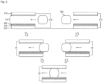
- Fig. 3 is a conceptual diagram describing the operation principle of an energy conversion device using the change of the contact surface of a liquid according to an exemplary embodiment of the present invention.
- an energy conversion device using the change of the contact surface of a liquid according to an exemplary embodiment of the present invention generates electrical energy as the ionic liquid or water 260 is moving between: the second electrode substrate 220, wherein an inorganic material layer 230, an organic material layer 240, and a hydrophobic material layer 250 are sequentially stacked; and the first electrode layer 210 wherein a hydrophobic material layer 250 is stacked, while both the second electrode substrate 220 and the first electrode substrate 210 are being touched by the liquid or water 260.
- Fig. 4a is a conceptual diagram describing the operation principle of an energy conversion device using the change of the contact surface of a liquid according to another exemplary embodiment of the present invention.
- Fig. 4a is an exemplary embodiment for the convenience of describing that the first electrode substrate 210 and the second electrode substrate 220, whereon the energy conversion layers are deposited, are immersed into the storage 400, wherein the ionic liquid or water 260 is stored, and thereafter pulled out, however, the claims should not be limitedly interpreted based on this example.
- Fig. 4 illustrates that the change of the contact area is generated by a simultaneous linear motion of a pair of the electrode substrates at a constant speed, however, an exemplary embodiment of the present example is not limited to this, and it may be equally applied to the case where a change occurs in the area which is being immersed in the liquid, that is the contact area, when a pair of electrode substrates are moving with different speeds from each other or in a non-linear manner.
- Fig. 4b is a cross-sectional view of an energy conversion device using the change of the contact surface of a liquid according to another exemplary embodiment of the present invention, which is described in Fig. 4a .
- the first electrode substrate 210 or the second electrode substrate 220 is configured such that the substrate 221 is surrounded by the electrode 222.
- an inorganic material layer 230, an organic material layer 240, and a hydrophobic material layer 250 are sequentially stacked on the electrode 222 which surrounds the substrate 221.
- a pair comprising a first electrode substrate 210 and a second electrode substrate 220
- Fig. 4a it may be comprised of an odd number of pairs.
- an energy conversion layer is comprised by stacking an inorganic material layer 230 and/or an organic material layer 240.
- a methods such as patterning, vacuum deposition, or spin coating may be used in forming such energy conversion layer.
- the order of stacking will not matter, however, they must be stacked adjacently.
- the inorganic material layer 230 and the organic material layer 240 may be alternately and repeatedly filed up when being stacked on the first electrode substrate 210 or on the second electrode substrate 220.
- an energy conversion layer can be formed by repeatedly stacking the inorganic material layer 230 and the organic material layer 240.
- an inorganic material layer 230 or an organic material layer 240 is deposited such that a structure for enlarging the contact surface contacting the ionic liquid or water 260 is formed thereat.
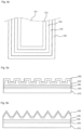
- Figs. 5a-5d are side views illustrating the exemplary embodiments of the energy conversion layer of an energy conversion device using change of contact surface contacting liquid according to an exemplary embodiment of the present invention.
- an inorganic material layer 530 is deposited on the electrode 520 which is included in the first electrode substrate 510 as an energy conversion layer of an energy conversion device using change of contact surface contacting liquid according to an exemplary embodiment of the present invention.
- the organic material layer 540 is stacked on the inorganic material layer 530 to form a micro structure having shapes such as a convex-concave shape shown in Fig. 5a , a sharply protruded shape shown in Fig. 5b , a semi sphere shape shown in Fig.
- the stacking order between the organic material layer 540 and the inorganic material layer 530 may be reversed, and the stacking material for forming the structure is not necessarily to be an organic material layer 540.
- a hydrophobic material layer 550 is stacked on the organic material layer 540 which is being stacked for forming the structure so that the shape of the structure is being maintained.
- the energy conversion devices using change of contact surface contacting liquid are plurally connected in an array form according to a preferred exemplary embodiment of the present invention. As previously described, this is to increase the generation efficiency of electrical energy by enlarging the change in the contact area between the electrodes and the ionic liquid or water.
- the substrates constituting the plural energy conversion device also form plural pairs, such multiple pairs of the electrodes are being supported by the common supporting structure (not shown), then being immersed in the ionic liquid or water, or being moved by a consistent external force and the like so that the contact area changes with time.
- a hydrophobic material layer 250 is stacked on the energy conversion layers 230 and 240 so as to facilitate the change of the contact surface between the electrodes 210 and 220 and the ionic liquid or water 260.
- the hydrophobic material layer 250 may be stacked on the first electrode substrate 210 or on the second electrode substrate 220 wherein no energy conversion layer is formed.
- an organic material layer 240 includes one material of polymethylmethacrylate(PMMA), polyethylene(PE), polystyrene(PS), polyvinylpyrrolidone(PVP), poly(4-vinylpenol)(PVP) or polyethersulfone(PES), poly(4-methoxyphenylacrylate; PMPA), poly(phenylacrylate)(PPA), poly(2,2,2-trifluoroethyl methacrylate)(PTFMA), cyanoethylpullulan(CYEPL), polyvinyl chloride(PVC), poly(parabanic acid resin)(PPA), poly(t-butylstyrene)(PTBS), polythienylenevinylene(PTV), polyvinylacetate(PVA), poly(vinyl alcohol)(PVA), poly(rmethylstyrene)(PAMS), poly(vinyl alcohol)-co-poly(vinyl)
- an inorganic material layer 230 includes at least one material of SiO 2 , TiO 2 , Al 2 O 3 , Ta 2 O 5 , tantalum pentoxide, zinc oxide(ZnO), tantalum pentoxide(Ta 2 O 5 ), yttrium oxide(Y 2 O 3 ), cerium oxide(CeO 2 ), titanium dioxide(TiO 2 ), barium titanate(BaTiO 3 ), barium zirconate titanate(BZT), zirconium dioxide(ZrO 2 ), lanthanum oxide(La 2 O 3 ), hafnon(HfSiO 4 ), lanthanum aluminate(LaAlO 3 ), silicon nitride(Si 3 N 4 ), perovskite materials, strontium titanate(SrTiO3), barium strontium titanate(BST), lead zirconate titanate(PZT), calcium copper titanate(CCTO), HfO 2 , apati
- a material having dielectric constant (K) lower than 4 may be used for the organic material 240, and a material having dielectric constant (K) higher than 5 may be used for the inorganic material 230.
- hydrophobic material layer 250 includes at least one of silane-based material, fluoropolymer material, trichlorosilane, trimethoxysilane, pentafluorophenylpropyltrichlorosilane, (benzyloxy) alkyltrimethoxysilane(BSM-22), (benzyloxy) alkyltrichlorosilane(BTS), hexamethyldisilazane(HMDS), octadecyltrichlorosilane(OTS), octadecyltrimethoxysilane(OTMS) and divinyltetramethyldisiloxane-bis(benzocyclobutene)(BCB).
- silane-based material includes at least one of silane-based material, fluoropolymer material, trichlorosilane, trimethoxysilane, pentafluorophenylpropyltrichlorosilane, (benzyl
- the electrodes used in the first electrode 210 or the second electrode 220 is an inorganic electrode which includes at least one of ITO, IGO, chrome, aluminum, indium zinc oxide(IZO), indium gallium zinc oxide(IGZO), ZnO, ZnO 2 and TiO 2 ; or a metal electrode including at least one of aluminum, iron or copper; or an organic electrode including at least one of polyethylenedioxythiophene(PEDOT), carbon nano tube(CNT), graphene, polyacetylene, polythiophene(PT), polypyrrole, polyparaphenylene(PPV), polyanilinep), poly sulfur nitride, stainless steel, iron alloy containing more than 10% of chrome, SUS 304, SUS 316, SUS 316L, Co-Cr alloy, Ti alloy, nitinol(Ni-Ti) and polyparaphenylenevinylene.
- ITO inorganic electrode which includes at least one of ITO, IGO, chrome, aluminum, indium zinc oxide(IZO),
- the first electrode substrate 210 or the second electrode substrate 220 is a metal substrate, a glass substrate, a ceramic substrate, or a polymer material substrate.
- the polymer material substrate is a plastic substrate or a film which includes at least one of polyethylene terephthalate(PET), polyarylate(PAR), polymethylmethacrylate(PMMA), polyethylenenaphthalate(PEN), 1polyethersulfone(PES), polyimide(PI), polycarbonate(PC) and fiber reinforced plastics(FRP).
- the ceramic substrate is a substrate using a ceramic material which includes at least one of alumina(Al 2 O 3 ), berilia(BeO), aluminum nitride(AIN), silicon carbide(SiC), mullite and silicon.
- the ionic liquid 260 includes at least one of NaCl, LiCl, NaNO 3 , Na 2 SiO 3 , AlCl 3 -NaCl, LiCl-KCl, H 2 O, KCL, Na, NaOH H 2 SO 4 , CH 3 COOH, HF, CuSO 4 , ethylene glycol, propylene glycol and AgCl.
- the present invention is configured to fill the space between the first electrode substrate 210 and the second electrode substrate 220 with a non-conductive gas.
- the space between the first electrode substrate 210 and the second electrode substrate 220 could be a normal aerial environment.
- the non-conductive gas includes at least one of air, oxygen, nitrogen, argon, helium, neon, krypton, xenon and radon.
- FIG. 6 is a structural drawing of an energy conversion device using the change of the contact surface of a liquid according to another exemplary embodiment of the present invention.
- an energy conversion device using the change of the contact surface of a liquid according to a preferred exemplary embodiment of the present invention includes a first electrode substrate 610 and a second electrode substrate 620 which are spaced apart and facing each other, wherein a conductive liquid 660, which is in contact with the electrode substrates and the contact surface thereof changes, is positioned between the electrode substrates.
- energy conversion layers 630 and 640 which generate electrical energy in accordance with the change in the contact surface contacting the conductive liquid 660, are stacked on the first electrode substrate 610 and the second electrode substrate 620.
- the conductive liquid 660 may use mercury, lithium, gallium, kalium, NaK, bismuth, tin, natrium, natrium-kalium alloy, and the like; the range of the specific resistivity is 1 ⁇ /cm to 1000 ⁇ /cm, and the dielectric constant K is lower than or equal to 5.
- a hydrophile material layer 650 is stacked on the energy conversion layers 630 and 640 so as to facilitate the change of the contact surface between the conductive liquid 660 and the electrode substrates 610 and 620.
- a hydrophile material layer 650 includes poly acrylic acid(PAA), acrylamides, maleic anhydride copolymers, methacrylate, ethacrylate, amine-functional polymers, amine-functional polymers, polystyrenesulfonate(PSS), vinyl acids, vinyl alcohols, and materials including one functional group of -NH, -CO-, amino group -NH 2 , hydroxyl group -OH or carboxyl group - COOH.
- the present invention may prevent blocking and mixing phenomena inside the channel, and also it does not require any lubricating layer.
- the technologies of prior art suggests an insulation layer comprising a single self assembly molecular monolayer and a single dielectric layer, or more layers of non-conductive layers, or the various combination thereof, however, the present invention suggests a structure for optimizing the energy conversion efficiency.
- an ionic liquid when using an ionic liquid, it is configured to have a structure of electrode/inorganic material layer/organic material layer/hydrophobic material layer or electrode/organic material layer/inorganic material layer/hydrophobic material layer (according to the stacking order) on at least one side of the substrate of the first electrode substate or the second electrode substrate; when using a conductive liquid, it is configured to have a structure of electrode/inorganic material layer/organic material layer/hydrophile material layer or electrode/organic material layer/inorganic material layer/hydrophile material layer (according to the stacking order) on both of the first electrode substrate and the second electrode substrate.
Landscapes
- Engineering & Computer Science (AREA)
- Power Engineering (AREA)
- Chemical & Material Sciences (AREA)
- Chemical Kinetics & Catalysis (AREA)
- Physical Or Chemical Processes And Apparatus (AREA)
Claims (10)
- Energieumwandlungsvorrichtung unter Verwendung einer Änderung der mit Flüssigkeit in Kontakt kommenden Kontaktfläche, umfassend:a) ein erstes Elektrodensubstrat (210) und ein zweites Elektrodensubstrat (220), die beabstandet sind und einander gegenüberliegen;b1) das erste Elektrodensubstrat (210) oder das zweite Elektrodensubstrat (220) mit einer darauf geschichteten oder abgeschiedenen Energieumwandlungsschicht (230, 240), oderb2) sowohl das erste Elektrodensubstrat (210) als auch das zweite Elektrodensubstrat (220) mit einer jeweiligen darauf geschichteten oder abgeschiedenen Energieumwandlungsschicht (230, 240),c) eine ionische Flüssigkeit oder Wasser (260), welche(s), im Fall b1), in Kontakt ist mit der Energieumwandlungsschicht (230, 240) und dem Elektrodensubstrat (210), auf das die Energieumwandlungsschicht (230, 240) nicht geschichtet oder abgeschieden ist, und welche(s), im Fall b2), in Kontakt mit den beiden jeweiligen Energieumwandlungsschichten (230, 240) ist;d) die jeweilige Energieumwandlungsschicht (230, 240), die auf mindestens eines von dem ersten Elektrodensubstrat (210) und dem zweiten Elektrodensubstrat (220) geschichtet oder abgeschieden ist, die entsprechend einer Veränderung eines Überlappungsbereichs der Kontaktfläche zwischen der ionischen Flüssigkeit oder Wasser (260) und der Energieumwandlungsschicht (230, 240), wenn sich die ionische Flüssigkeit oder Wasser (260) im Fall b1) zwischen dem Elektrodensubstrat (210 oder 220) und der Energieumwandlungsschicht (230, 240) oder im Fall b2) zwischen den Energieumwandlungsschichten (230, 240) bewegt, elektrische Energie erzeugt,e) wobei die Energieumwandlungsschicht (230, 240) mindestens eine von einer Schicht aus anorganischem Material (230), einer Schicht aus organischem Material (240) oder einer eine Mischung aus organischen und anorganischen Materialien umfassenden Schicht umfasst und wobei die Schicht aus anorganischem Material (230) und/oder die Schicht aus organischem Material (240) als Mikrostruktur mit Formen wie z. B. einer konvexkonkaven Form, einer spitz herausgestreckten Form, einer Halbkugelform oder einer Form einer kugelförmigen Vertiefung zur Vergrößerung der mit der ionischen Flüssigkeit oder Wasser (260) in Kontakt kommenden Kontaktfläche ausgebildet ist.
- Energieumwandlungsvorrichtung unter Verwendung der Änderung der mit Flüssigkeit in Kontakt kommenden Kontaktfläche nach Anspruch 1, wobei die Energieumwandlungsvorrichtung mit (einer) anderen Energieumwandlungsvorrichtung(en) in einer Array-Form verbunden ist.
- Energieumwandlungsvorrichtung unter Verwendung der Änderung der mit Flüssigkeit in Kontakt kommenden Kontaktfläche nach Anspruch 2, wobei zumindest ein Teil einer Mehrzahl von Substraten, die eine Mehrzahl von Energieumwandlungsvorrichtungen, umfassend die Energieumwandlungsvorrichtung und die andere(n) Energieumwandlungsvorrichtung(en), bilden, durch eine übliche stützende Struktur gestützt sind.
- Energieumwandlungsvorrichtung unter Verwendung der Änderung der mit Flüssigkeit in Kontakt kommenden Kontaktfläche nach Anspruch 1, wobei die mindestens eine von der Energieumwandlungsschicht (230, 240) konfiguriert ist zum Erzeugen von elektrischer Energie durch Bewegen auf solche Weise, dass sich ein Grad des Eintauchens davon in die ionische Flüssigkeit oder Wasser (260) verändert.
- Energieumwandlungsvorrichtung unter Verwendung der Änderung der mit Flüssigkeit in Kontakt kommenden Kontaktfläche nach Anspruch 1, wobei, im Fall b1), eine Schicht aus hydrophobem Material (250) jeweils auf die Energieumwandlungsschicht (230, 240) und das Elektrodensubstrat (210), auf das die Energieumwandlungsschicht (230, 240) nicht geschichtet oder abgeschieden ist, geschichtet ist, um die Änderung der mit der ionischen Flüssigkeit oder Wasser (260) in Kontakt kommenden Kontaktfläche zu erleichtern.
- Energieumwandlungsvorrichtung unter Verwendung der Änderung der mit Flüssigkeit in Kontakt kommenden Kontaktfläche nach Anspruch 5, wobei die Schicht aus hydrophobem Material (250) mindestens eines umfasst von: Material auf Silanbasis, Fluorpolymermaterial, Trichlorsilan, Trimethoxysilan, Pentafluorphenylpropyltrichlorsilan, (Benzyloxy)alkyltrimethoxysilan (BSM-22), (Benzyloxy)alkyltrichlorsilan (BTS), Hexamethyldisilazan (HMDS), Octadecyltrichlorsilan (OTS), Octadecyltrimethoxysilan (OTMS) und Divinyltetramethyldisiloxan-bis(benzocyclobuten) (BCB).
- Energieumwandlungsvorrichtung unter Verwendung der Änderung der mit Flüssigkeit in Kontakt kommenden Kontaktfläche nach Anspruch 1, wobei die ionische Flüssigkeit mindestens eines enthält von: NaCl, LiCl, NaNO3, Na2SiO3, AlCl3-NaCl, LiCl-KCl, H2O, KCL, Na, NaOH H2SO4, CH3COOH, HF, CuSO4, Ethylenglykol, Propylenglykol und AgCl.
- Energieumwandlungsvorrichtung unter Verwendung der Änderung der mit Flüssigkeit in Kontakt kommenden Kontaktfläche nach einem der Ansprüche 1 bis 7, wobei die Energieumwandlungsschicht eine Schicht aus organischem Material (240) umfasst, umfassend mindestens ein Material von: Polymethylmethacrylat (PMMA), Polyethylen (PE), Polystyrol (PS), Polyvinylpyrrolidon (PVP), Poly(4-vinylpenol) (PVP) oder Polyethersulfon (PES), Poly(4-methoxyphenylacrylat) PMPA;, Poly(phenylacrylat) (PPA), Poly(2,2,2-trifluorethylmethacrylat) (PTFMA), Cyanoethylpullulan (CYEPL), Polyvinylchlorid (PVC), Poly-(parabansäureharz ) (PPA), Poly(t-butylstyrol) (PTBS), Polythienylenvinylen (PTV), Polyvinylacetat (PVA), Poly (vinylalkohol) (PVA), Poly (r-methylstyrol) (PAMS), Poly(vinylalkohol)-co-Poly(vinylacetat)-co-Poly (itaconsäure) (PVAIA), Polyolefin, Polyacrylat, Parylene-C, Polyimid, Octadecyltrichlorsilan (OTS), Poly(triarylamin) (PTTA), Poly-3-hexylthiophen (P3HT), vernetztem Poly-4-vinylphenol (vernetztem PVP), Poly(perfluoralkenylvinylether), Nylon-6, n-Octadecylphosphonsäure (ODPA), Polytetrafluorethylen (PTFE), Silikon, Polyurethan, Latex, Celluloseacetat, Poly(hydroxyethylmethacrylat) (PHEMA), Polylactid (PLA), Polyglycolid (PGA) und Poly-glycolid-co-lactid (PGLA); und eine Schicht aus anorganischem Material (230) umfasst, umfassend mindestens ein Material von: SiO2, TiO2, Al2O3, Ta2O5, Tantalpentoxid, Zinkoxid (ZnO), Tantalpentoxid (Ta2O5), Yttriumoxid (Y2O3), Ceroxid (CeO2), Titandioxid (TiO2), Bariumtitanat (BaTiO3), Barium-Zirconat-Titanat (BZT), Zirconiumdioxid (ZrO2), Lanthanoxid (La2O3), Hafnon (HfSiO4), Lanthanaluminat (LaAlO3), Siliciumnitrid (Si3N4), Perowskit-Materialien, Strontiumtitanat (SrTiO3), Barium-Strontium-Titanat (BST), Blei-Zirconat-Titanat (PZT), Calcium-Kupfer-Titanat (CCTO), oder HfO2, Apatit (A10(MO4)6X2), Hydroxyapatit (Ca10(PO4)6(OH)2), Tricalciumphosphat (Ca3(PO4)2), Na2O-CaO-SiO2 und Bioglas (CaO-SiO2-P2O5).
- Energieumwandlungsvorrichtung unter Verwendung der Änderung der mit Flüssigkeit in Kontakt kommenden Kontaktfläche nach einem der Ansprüche 1 bis 8,wobei das erste Elektrodensubstrat (210) oder das zweite Elektrodensubstrat (220) eine Elektrode umfasst,wobei die Elektrode ist: eine anorganische Elektrode, umfassend mindestens eines von ITO, IGO, Chrom, Aluminium, Indium-Zink-Oxid (IZO), Indium-Gallium-Zink-Oxid (IGZO), ZnO, ZnO2 und TiO2; oder eine Metallelektrode, umfassend mindestens eines von Platin, Gold, Silber, Aluminium, Eisen und Kupfer; oder eine organische Elektrode, umfassend mindestens eines von Polyethylendioxythiophen (PEDOT), Kohlenstoffnanoröhre (CNT), Graphen, Polyacetylen, Polythiophen (PT), Polypyrrol, Polyparaphenylen (PPV), Polyanilinp, Polyschwefelnitrid, nicht rostendem Stahl, Eisenlegierung, die mehr als 10 % Chrom enthält, SUS 304, SUS 316, SUS 316L, Co-Cr-Legierung, Ti-Legierung, Nitinol (Ni-Ti) und Polyparaphenylenvinylen.
- Energieumwandlungsvorrichtung unter Verwendung der Änderung der mit Flüssigkeit in Kontakt kommenden Kontaktfläche nach einem der Ansprüche 1 bis 9,wobei mindestens eines von dem ersten Elektrodensubstrat (210) oder dem zweiten Elektrodensubstrat (220) ein Metallsubstrat, ein Glassubstrat, ein keramisches Substrat oder ein Substrat aus Polymermaterial ist,wobei das Substrat aus Polymermaterial ein Kunststoffsubstrat oder eine Folie ist, welche(s) mindestens eines von Polyethylenterephthalat (PET), Polyarylat (PAR), Polymethylmethacrylat (PMMA), Polyethylennaphthalat (PEN), Polyethersulfon (PES), Polyimid (PI), Polycarbonat (PC) und faserverstärkten Kunststoffen (FVK) umfasst, unddas keramische Substrat ein Substrat unter Verwendung eines keramischen Materials, das mindestens eines von Aluminiumoxid (Al2O3), Berylliumoxid (BeO), Aluminiumnitrid (AlN), Siliciumcarbid (SiC), Mullit und Silicium umfasst, ist.
Applications Claiming Priority (2)
| Application Number | Priority Date | Filing Date | Title |
|---|---|---|---|
| KR1020120134389A KR101358286B1 (ko) | 2012-11-26 | 2012-11-26 | 액체와의 접촉면 변화를 이용한 에너지 전환 장치 |
| PCT/KR2013/010716 WO2014081256A1 (ko) | 2012-11-26 | 2013-11-25 | 액체와의 접촉면 변화를 이용한 에너지 전환 장치 |
Publications (4)
| Publication Number | Publication Date |
|---|---|
| EP2924869A1 EP2924869A1 (de) | 2015-09-30 |
| EP2924869A4 EP2924869A4 (de) | 2016-07-27 |
| EP2924869B1 true EP2924869B1 (de) | 2025-04-02 |
| EP2924869C0 EP2924869C0 (de) | 2025-04-02 |
Family
ID=50269821
Family Applications (1)
| Application Number | Title | Priority Date | Filing Date |
|---|---|---|---|
| EP13857613.7A Active EP2924869B1 (de) | 2012-11-26 | 2013-11-25 | Energieumwandlungsvorrichtung unter verwendung von änderung der kontaktfläche mit flüssigkeit |
Country Status (5)
| Country | Link |
|---|---|
| US (1) | US9954463B2 (de) |
| EP (1) | EP2924869B1 (de) |
| JP (1) | JP5941229B2 (de) |
| KR (1) | KR101358286B1 (de) |
| WO (1) | WO2014081256A1 (de) |
Families Citing this family (11)
| Publication number | Priority date | Publication date | Assignee | Title |
|---|---|---|---|---|
| KR101358286B1 (ko) * | 2012-11-26 | 2014-02-12 | 서울대학교산학협력단 | 액체와의 접촉면 변화를 이용한 에너지 전환 장치 |
| KR101435502B1 (ko) * | 2012-11-29 | 2014-09-02 | 전자부품연구원 | 액체를 이용한 플렉서블 에너지 전환 장치 |
| KR101407489B1 (ko) | 2012-11-29 | 2014-06-13 | 서울대학교산학협력단 | 액체를 이용한 에너지 전환 장치 |
| KR101358295B1 (ko) * | 2012-12-21 | 2014-02-05 | 서울대학교산학협력단 | 액체를 이용한 에너지 전환 기판 |
| US20140346782A1 (en) * | 2013-05-23 | 2014-11-27 | Pusan National University Industry-University Cooperation Foundation | Micro power generator and power generation method using liquid droplet |
| EP3096338B1 (de) * | 2015-05-21 | 2019-07-24 | Nokia Technologies Oy | Vorrichtung und verfahren zur bereitstellung einer zeitvariablen spannung |
| US11189432B2 (en) * | 2016-10-24 | 2021-11-30 | Indian Institute Of Technology, Guwahati | Microfluidic electrical energy harvester |
| CN107482953A (zh) * | 2017-09-16 | 2017-12-15 | 邱丹丹 | 基于润湿梯度表面的液滴自驱动能量转换装置及制备方法 |
| US10868479B2 (en) * | 2018-10-04 | 2020-12-15 | Stmicroelectronics S.R.L. | Inverse electrowetting and magnetic energy harvesting and scavenging methods, circuits and systems |
| KR102195506B1 (ko) * | 2018-12-14 | 2020-12-28 | 서울대학교산학협력단 | 중금속 이온탐지 센서 및 이를 이용한 중금속 이온탐지 방법 |
| US11239768B2 (en) * | 2019-10-24 | 2022-02-01 | City University Of Hong Kong | Liquid droplet powered electricity generator |
Citations (1)
| Publication number | Priority date | Publication date | Assignee | Title |
|---|---|---|---|---|
| US7898096B1 (en) * | 2007-08-22 | 2011-03-01 | Thomas Nikita Krupenkin | Method and apparatus for energy harvesting using microfluidics |
Family Cites Families (20)
| Publication number | Priority date | Publication date | Assignee | Title |
|---|---|---|---|---|
| JP3448118B2 (ja) | 1994-11-08 | 2003-09-16 | 東洋化工株式会社 | 発電装置 |
| JP3501216B2 (ja) * | 2000-03-31 | 2004-03-02 | 慶和 劉 | 電歪伸縮材を利用した駆動装置 |
| US7446450B2 (en) | 2004-06-07 | 2008-11-04 | California Institute Of Technology | Method and system using liquid dielectric for electrostatic power generation |
| KR20090018470A (ko) | 2007-08-17 | 2009-02-20 | 한국전자통신연구원 | 마이크로 에너지 발전-저장 소자 |
| FR2925792B1 (fr) * | 2007-12-21 | 2012-12-07 | Commissariat Energie Atomique | Dispositif de recuperation d'energie a electrode liquide |
| KR101458211B1 (ko) | 2008-07-08 | 2014-11-04 | 주식회사 엘지화학 | 독립된 분리막을 포함하지 않는 이차전지 |
| JP5628178B2 (ja) * | 2008-09-16 | 2014-11-19 | コーニンクレッカ フィリップス エヌ ヴェ | 容量性マイクロマシン超音波トランスデューサ |
| JP5686558B2 (ja) * | 2009-09-17 | 2015-03-18 | 株式会社ユポ・コーポレーション | エネルギー変換用フィルム |
| EP2400573A1 (de) * | 2010-06-23 | 2011-12-28 | Bayer MaterialScience AG | Elektromechanischer Wandler, Verfahren zu dessen Herstellung und Verwendung desselben |
| JP2012055095A (ja) | 2010-09-01 | 2012-03-15 | Nippon Shokubai Co Ltd | エレクトレット材料用重合体組成物、エレクトレット材料 |
| US9184676B2 (en) * | 2011-10-31 | 2015-11-10 | Wisconsin Alumni Research Foundation | Varying capacitance rotating electrical machine |
| JP2013098077A (ja) * | 2011-11-02 | 2013-05-20 | Sony Corp | 燃料電池の製造方法、並びに燃料電池および電子機器 |
| TWI442088B (zh) * | 2012-02-24 | 2014-06-21 | Ind Tech Res Inst | 電濕潤顯示元件 |
| DE102012216564A1 (de) * | 2012-09-17 | 2014-03-20 | Robert Bosch Gmbh | Aggregat und Vielschichtaktor |
| KR101358286B1 (ko) * | 2012-11-26 | 2014-02-12 | 서울대학교산학협력단 | 액체와의 접촉면 변화를 이용한 에너지 전환 장치 |
| KR101407489B1 (ko) * | 2012-11-29 | 2014-06-13 | 서울대학교산학협력단 | 액체를 이용한 에너지 전환 장치 |
| KR101435502B1 (ko) * | 2012-11-29 | 2014-09-02 | 전자부품연구원 | 액체를 이용한 플렉서블 에너지 전환 장치 |
| CN103368458B (zh) * | 2012-11-30 | 2016-01-20 | 北京纳米能源与系统研究所 | 脉冲发电机和发电机组 |
| US20140216559A1 (en) * | 2013-02-07 | 2014-08-07 | Advanced Liquid Logic, Inc. | Droplet actuator with local variation in gap height to assist in droplet splitting and merging operations |
| JP2015223640A (ja) * | 2014-05-26 | 2015-12-14 | セイコーエプソン株式会社 | Mems構造体、電子機器および移動体 |
-
2012
- 2012-11-26 KR KR1020120134389A patent/KR101358286B1/ko active Active
-
2013
- 2013-11-25 US US14/646,995 patent/US9954463B2/en active Active
- 2013-11-25 WO PCT/KR2013/010716 patent/WO2014081256A1/ko not_active Ceased
- 2013-11-25 EP EP13857613.7A patent/EP2924869B1/de active Active
- 2013-11-25 JP JP2015543988A patent/JP5941229B2/ja active Active
Patent Citations (1)
| Publication number | Priority date | Publication date | Assignee | Title |
|---|---|---|---|---|
| US7898096B1 (en) * | 2007-08-22 | 2011-03-01 | Thomas Nikita Krupenkin | Method and apparatus for energy harvesting using microfluidics |
Also Published As
| Publication number | Publication date |
|---|---|
| US9954463B2 (en) | 2018-04-24 |
| EP2924869A1 (de) | 2015-09-30 |
| KR101358286B1 (ko) | 2014-02-12 |
| JP5941229B2 (ja) | 2016-06-29 |
| JP2016502391A (ja) | 2016-01-21 |
| US20150295516A1 (en) | 2015-10-15 |
| EP2924869C0 (de) | 2025-04-02 |
| WO2014081256A1 (ko) | 2014-05-30 |
| EP2924869A4 (de) | 2016-07-27 |
Similar Documents
| Publication | Publication Date | Title |
|---|---|---|
| US9954463B2 (en) | Energy conversion device using change of contact surface with liquid | |
| EP2930359B1 (de) | Energieumwandlungsvorrichtung unter verwendung einer flüssigkeit | |
| EP2838191B1 (de) | Energieumwandlungsvorrichtung mit änderung der kontaktfläche und des kontaktwinkels von flüssigkeit | |
| KR101411337B1 (ko) | 적층구조를 가지는 액체를 이용한 에너지 전환 장치 | |
| EP2830108B1 (de) | Energieumwandlungssubstrat unter verwendung von flüssigkeit | |
| EP2927490B1 (de) | Flexible energieumwandlungsvorrichtung unter verwendung einer flüssigkeit | |
| US10291153B2 (en) | Electrode stacked energy conversion device using liquid | |
| KR101721662B1 (ko) | 액체 방울 측정 장치 | |
| KR101468642B1 (ko) | 액체를 이용한 회전형 에너지 전환 장치 | |
| KR101810036B1 (ko) | 액체를 이용한 에너지 전환 장치 | |
| KR101403017B1 (ko) | 관통홀을 가지는 액체를 이용한 에너지 전환 장치 |
Legal Events
| Date | Code | Title | Description |
|---|---|---|---|
| PUAI | Public reference made under article 153(3) epc to a published international application that has entered the european phase |
Free format text: ORIGINAL CODE: 0009012 |
|
| 17P | Request for examination filed |
Effective date: 20150605 |
|
| AK | Designated contracting states |
Kind code of ref document: A1 Designated state(s): AL AT BE BG CH CY CZ DE DK EE ES FI FR GB GR HR HU IE IS IT LI LT LU LV MC MK MT NL NO PL PT RO RS SE SI SK SM TR |
|
| AX | Request for extension of the european patent |
Extension state: BA ME |
|
| RAP1 | Party data changed (applicant data changed or rights of an application transferred) |
Owner name: KOREA ELECTRONICS TECHNOLOGY INSTITUTE Owner name: SEOUL NATIONAL UNIVERSITY R&DB FOUNDATION |
|
| DAX | Request for extension of the european patent (deleted) | ||
| RAP1 | Party data changed (applicant data changed or rights of an application transferred) |
Owner name: KOREA ELECTRONICS TECHNOLOGY INSTITUTE |
|
| RA4 | Supplementary search report drawn up and despatched (corrected) |
Effective date: 20160628 |
|
| RIC1 | Information provided on ipc code assigned before grant |
Ipc: H02N 1/08 20060101ALI20160622BHEP Ipc: H02N 3/00 20060101AFI20160622BHEP |
|
| STAA | Information on the status of an ep patent application or granted ep patent |
Free format text: STATUS: EXAMINATION IS IN PROGRESS |
|
| 17Q | First examination report despatched |
Effective date: 20181019 |
|
| GRAP | Despatch of communication of intention to grant a patent |
Free format text: ORIGINAL CODE: EPIDOSNIGR1 |
|
| STAA | Information on the status of an ep patent application or granted ep patent |
Free format text: STATUS: GRANT OF PATENT IS INTENDED |
|
| INTG | Intention to grant announced |
Effective date: 20241025 |
|
| GRAS | Grant fee paid |
Free format text: ORIGINAL CODE: EPIDOSNIGR3 |
|
| GRAA | (expected) grant |
Free format text: ORIGINAL CODE: 0009210 |
|
| STAA | Information on the status of an ep patent application or granted ep patent |
Free format text: STATUS: THE PATENT HAS BEEN GRANTED |
|
| AK | Designated contracting states |
Kind code of ref document: B1 Designated state(s): AL AT BE BG CH CY CZ DE DK EE ES FI FR GB GR HR HU IE IS IT LI LT LU LV MC MK MT NL NO PL PT RO RS SE SI SK SM TR |
|
| REG | Reference to a national code |
Ref country code: GB Ref legal event code: FG4D |
|
| REG | Reference to a national code |
Ref country code: CH Ref legal event code: EP |
|
| REG | Reference to a national code |
Ref country code: IE Ref legal event code: FG4D |
|
| REG | Reference to a national code |
Ref country code: DE Ref legal event code: R096 Ref document number: 602013086638 Country of ref document: DE |
|
| U01 | Request for unitary effect filed |
Effective date: 20250416 |
|
| U07 | Unitary effect registered |
Designated state(s): AT BE BG DE DK EE FI FR IT LT LU LV MT NL PT RO SE SI Effective date: 20250424 |
|
| PG25 | Lapsed in a contracting state [announced via postgrant information from national office to epo] |
Ref country code: ES Free format text: LAPSE BECAUSE OF FAILURE TO SUBMIT A TRANSLATION OF THE DESCRIPTION OR TO PAY THE FEE WITHIN THE PRESCRIBED TIME-LIMIT Effective date: 20250402 |
|
| PG25 | Lapsed in a contracting state [announced via postgrant information from national office to epo] |
Ref country code: GR Free format text: LAPSE BECAUSE OF FAILURE TO SUBMIT A TRANSLATION OF THE DESCRIPTION OR TO PAY THE FEE WITHIN THE PRESCRIBED TIME-LIMIT Effective date: 20250703 Ref country code: NO Free format text: LAPSE BECAUSE OF FAILURE TO SUBMIT A TRANSLATION OF THE DESCRIPTION OR TO PAY THE FEE WITHIN THE PRESCRIBED TIME-LIMIT Effective date: 20250702 |
|
| PG25 | Lapsed in a contracting state [announced via postgrant information from national office to epo] |
Ref country code: PL Free format text: LAPSE BECAUSE OF FAILURE TO SUBMIT A TRANSLATION OF THE DESCRIPTION OR TO PAY THE FEE WITHIN THE PRESCRIBED TIME-LIMIT Effective date: 20250402 |
|
| PG25 | Lapsed in a contracting state [announced via postgrant information from national office to epo] |
Ref country code: HR Free format text: LAPSE BECAUSE OF FAILURE TO SUBMIT A TRANSLATION OF THE DESCRIPTION OR TO PAY THE FEE WITHIN THE PRESCRIBED TIME-LIMIT Effective date: 20250402 |
|
| PG25 | Lapsed in a contracting state [announced via postgrant information from national office to epo] |
Ref country code: RS Free format text: LAPSE BECAUSE OF FAILURE TO SUBMIT A TRANSLATION OF THE DESCRIPTION OR TO PAY THE FEE WITHIN THE PRESCRIBED TIME-LIMIT Effective date: 20250702 |
|
| PG25 | Lapsed in a contracting state [announced via postgrant information from national office to epo] |
Ref country code: IS Free format text: LAPSE BECAUSE OF FAILURE TO SUBMIT A TRANSLATION OF THE DESCRIPTION OR TO PAY THE FEE WITHIN THE PRESCRIBED TIME-LIMIT Effective date: 20250802 |
|
| U20 | Renewal fee for the european patent with unitary effect paid |
Year of fee payment: 13 Effective date: 20251124 |
|
| PG25 | Lapsed in a contracting state [announced via postgrant information from national office to epo] |
Ref country code: SM Free format text: LAPSE BECAUSE OF FAILURE TO SUBMIT A TRANSLATION OF THE DESCRIPTION OR TO PAY THE FEE WITHIN THE PRESCRIBED TIME-LIMIT Effective date: 20250402 |
|
| PG25 | Lapsed in a contracting state [announced via postgrant information from national office to epo] |
Ref country code: CZ Free format text: LAPSE BECAUSE OF FAILURE TO SUBMIT A TRANSLATION OF THE DESCRIPTION OR TO PAY THE FEE WITHIN THE PRESCRIBED TIME-LIMIT Effective date: 20250402 |
|
| PG25 | Lapsed in a contracting state [announced via postgrant information from national office to epo] |
Ref country code: SK Free format text: LAPSE BECAUSE OF FAILURE TO SUBMIT A TRANSLATION OF THE DESCRIPTION OR TO PAY THE FEE WITHIN THE PRESCRIBED TIME-LIMIT Effective date: 20250402 |
|
| PLBE | No opposition filed within time limit |
Free format text: ORIGINAL CODE: 0009261 |
|
| STAA | Information on the status of an ep patent application or granted ep patent |
Free format text: STATUS: NO OPPOSITION FILED WITHIN TIME LIMIT |
|
| REG | Reference to a national code |
Ref country code: CH Ref legal event code: L10 Free format text: ST27 STATUS EVENT CODE: U-0-0-L10-L00 (AS PROVIDED BY THE NATIONAL OFFICE) Effective date: 20260211 |
|
| 26N | No opposition filed |
Effective date: 20260105 |