EP2924398A2 - Sensor assembly - Google Patents
Sensor assembly Download PDFInfo
- Publication number
- EP2924398A2 EP2924398A2 EP15160357.8A EP15160357A EP2924398A2 EP 2924398 A2 EP2924398 A2 EP 2924398A2 EP 15160357 A EP15160357 A EP 15160357A EP 2924398 A2 EP2924398 A2 EP 2924398A2
- Authority
- EP
- European Patent Office
- Prior art keywords
- sensor
- arrangement according
- head
- holder
- sensor head
- Prior art date
- Legal status (The legal status is an assumption and is not a legal conclusion. Google has not performed a legal analysis and makes no representation as to the accuracy of the status listed.)
- Ceased
Links
Images


Classifications
-
- B—PERFORMING OPERATIONS; TRANSPORTING
- B60—VEHICLES IN GENERAL
- B60R—VEHICLES, VEHICLE FITTINGS, OR VEHICLE PARTS, NOT OTHERWISE PROVIDED FOR
- B60R11/00—Arrangements for holding or mounting articles, not otherwise provided for
- B60R11/04—Mounting of cameras operative during drive; Arrangement of controls thereof relative to the vehicle
-
- B—PERFORMING OPERATIONS; TRANSPORTING
- B60—VEHICLES IN GENERAL
- B60R—VEHICLES, VEHICLE FITTINGS, OR VEHICLE PARTS, NOT OTHERWISE PROVIDED FOR
- B60R21/00—Arrangements or fittings on vehicles for protecting or preventing injuries to occupants or pedestrians in case of accidents or other traffic risks
- B60R21/01—Electrical circuits for triggering passive safety arrangements, e.g. airbags, safety belt tighteners, in case of vehicle accidents or impending vehicle accidents
- B60R21/013—Electrical circuits for triggering passive safety arrangements, e.g. airbags, safety belt tighteners, in case of vehicle accidents or impending vehicle accidents including means for detecting collisions, impending collisions or roll-over
- B60R21/0134—Electrical circuits for triggering passive safety arrangements, e.g. airbags, safety belt tighteners, in case of vehicle accidents or impending vehicle accidents including means for detecting collisions, impending collisions or roll-over responsive to imminent contact with an obstacle, e.g. using radar systems
-
- B—PERFORMING OPERATIONS; TRANSPORTING
- B60—VEHICLES IN GENERAL
- B60R—VEHICLES, VEHICLE FITTINGS, OR VEHICLE PARTS, NOT OTHERWISE PROVIDED FOR
- B60R21/00—Arrangements or fittings on vehicles for protecting or preventing injuries to occupants or pedestrians in case of accidents or other traffic risks
- B60R21/34—Protecting non-occupants of a vehicle, e.g. pedestrians
-
- G—PHYSICS
- G01—MEASURING; TESTING
- G01D—MEASURING NOT SPECIALLY ADAPTED FOR A SPECIFIC VARIABLE; ARRANGEMENTS FOR MEASURING TWO OR MORE VARIABLES NOT COVERED IN A SINGLE OTHER SUBCLASS; TARIFF METERING APPARATUS; MEASURING OR TESTING NOT OTHERWISE PROVIDED FOR
- G01D11/00—Component parts of measuring arrangements not specially adapted for a specific variable
- G01D11/30—Supports specially adapted for an instrument; Supports specially adapted for a set of instruments
-
- G—PHYSICS
- G01—MEASURING; TESTING
- G01S—RADIO DIRECTION-FINDING; RADIO NAVIGATION; DETERMINING DISTANCE OR VELOCITY BY USE OF RADIO WAVES; LOCATING OR PRESENCE-DETECTING BY USE OF THE REFLECTION OR RERADIATION OF RADIO WAVES; ANALOGOUS ARRANGEMENTS USING OTHER WAVES
- G01S7/00—Details of systems according to groups G01S13/00, G01S15/00, G01S17/00
- G01S7/52—Details of systems according to groups G01S13/00, G01S15/00, G01S17/00 of systems according to group G01S15/00
- G01S7/521—Constructional features
-
- B—PERFORMING OPERATIONS; TRANSPORTING
- B60—VEHICLES IN GENERAL
- B60R—VEHICLES, VEHICLE FITTINGS, OR VEHICLE PARTS, NOT OTHERWISE PROVIDED FOR
- B60R11/00—Arrangements for holding or mounting articles, not otherwise provided for
- B60R2011/0001—Arrangements for holding or mounting articles, not otherwise provided for characterised by position
- B60R2011/004—Arrangements for holding or mounting articles, not otherwise provided for characterised by position outside the vehicle
-
- B—PERFORMING OPERATIONS; TRANSPORTING
- B60—VEHICLES IN GENERAL
- B60R—VEHICLES, VEHICLE FITTINGS, OR VEHICLE PARTS, NOT OTHERWISE PROVIDED FOR
- B60R11/00—Arrangements for holding or mounting articles, not otherwise provided for
- B60R2011/0042—Arrangements for holding or mounting articles, not otherwise provided for characterised by mounting means
- B60R2011/0049—Arrangements for holding or mounting articles, not otherwise provided for characterised by mounting means for non integrated articles
- B60R2011/0064—Connection with the article
- B60R2011/0066—Connection with the article using screws, bolts, rivets or the like
-
- B—PERFORMING OPERATIONS; TRANSPORTING
- B60—VEHICLES IN GENERAL
- B60R—VEHICLES, VEHICLE FITTINGS, OR VEHICLE PARTS, NOT OTHERWISE PROVIDED FOR
- B60R11/00—Arrangements for holding or mounting articles, not otherwise provided for
- B60R2011/0042—Arrangements for holding or mounting articles, not otherwise provided for characterised by mounting means
- B60R2011/0049—Arrangements for holding or mounting articles, not otherwise provided for characterised by mounting means for non integrated articles
- B60R2011/0064—Connection with the article
- B60R2011/0075—Connection with the article using a containment or docking space
-
- B—PERFORMING OPERATIONS; TRANSPORTING
- B60—VEHICLES IN GENERAL
- B60R—VEHICLES, VEHICLE FITTINGS, OR VEHICLE PARTS, NOT OTHERWISE PROVIDED FOR
- B60R21/00—Arrangements or fittings on vehicles for protecting or preventing injuries to occupants or pedestrians in case of accidents or other traffic risks
- B60R21/01—Electrical circuits for triggering passive safety arrangements, e.g. airbags, safety belt tighteners, in case of vehicle accidents or impending vehicle accidents
- B60R2021/01006—Mounting of electrical components in vehicles
-
- G—PHYSICS
- G01—MEASURING; TESTING
- G01S—RADIO DIRECTION-FINDING; RADIO NAVIGATION; DETERMINING DISTANCE OR VELOCITY BY USE OF RADIO WAVES; LOCATING OR PRESENCE-DETECTING BY USE OF THE REFLECTION OR RERADIATION OF RADIO WAVES; ANALOGOUS ARRANGEMENTS USING OTHER WAVES
- G01S13/00—Systems using the reflection or reradiation of radio waves, e.g. radar systems; Analogous systems using reflection or reradiation of waves whose nature or wavelength is irrelevant or unspecified
- G01S13/88—Radar or analogous systems specially adapted for specific applications
- G01S13/93—Radar or analogous systems specially adapted for specific applications for anti-collision purposes
- G01S13/931—Radar or analogous systems specially adapted for specific applications for anti-collision purposes of land vehicles
- G01S2013/9327—Sensor installation details
-
- G—PHYSICS
- G01—MEASURING; TESTING
- G01S—RADIO DIRECTION-FINDING; RADIO NAVIGATION; DETERMINING DISTANCE OR VELOCITY BY USE OF RADIO WAVES; LOCATING OR PRESENCE-DETECTING BY USE OF THE REFLECTION OR RERADIATION OF RADIO WAVES; ANALOGOUS ARRANGEMENTS USING OTHER WAVES
- G01S15/00—Systems using the reflection or reradiation of acoustic waves, e.g. sonar systems
- G01S15/88—Sonar systems specially adapted for specific applications
- G01S15/93—Sonar systems specially adapted for specific applications for anti-collision purposes
- G01S15/931—Sonar systems specially adapted for specific applications for anti-collision purposes of land vehicles
- G01S2015/937—Sonar systems specially adapted for specific applications for anti-collision purposes of land vehicles sensor installation details
-
- G—PHYSICS
- G01—MEASURING; TESTING
- G01S—RADIO DIRECTION-FINDING; RADIO NAVIGATION; DETERMINING DISTANCE OR VELOCITY BY USE OF RADIO WAVES; LOCATING OR PRESENCE-DETECTING BY USE OF THE REFLECTION OR RERADIATION OF RADIO WAVES; ANALOGOUS ARRANGEMENTS USING OTHER WAVES
- G01S7/00—Details of systems according to groups G01S13/00, G01S15/00, G01S17/00
- G01S7/02—Details of systems according to groups G01S13/00, G01S15/00, G01S17/00 of systems according to group G01S13/00
- G01S7/027—Constructional details of housings, e.g. form, type, material or ruggedness
-
- G—PHYSICS
- G01—MEASURING; TESTING
- G01S—RADIO DIRECTION-FINDING; RADIO NAVIGATION; DETERMINING DISTANCE OR VELOCITY BY USE OF RADIO WAVES; LOCATING OR PRESENCE-DETECTING BY USE OF THE REFLECTION OR RERADIATION OF RADIO WAVES; ANALOGOUS ARRANGEMENTS USING OTHER WAVES
- G01S7/00—Details of systems according to groups G01S13/00, G01S15/00, G01S17/00
- G01S7/02—Details of systems according to groups G01S13/00, G01S15/00, G01S17/00 of systems according to group G01S13/00
- G01S7/40—Means for monitoring or calibrating
- G01S7/4004—Means for monitoring or calibrating of parts of a radar system
- G01S7/4026—Antenna boresight
Definitions
- the invention relates to a sensor arrangement, in particular for sensors to be mounted on the outside of a vehicle for monitoring the vehicle environment according to the preamble of claim 1.
- sensors of various types are always used for monitoring the vehicle environment.
- Ultrasonic sensors for parking assistance systems radar sensors for distance monitoring systems, cameras for indirect vision systems and thermal imaging cameras for detecting persons in close proximity to vehicles and the like are used.
- such sensors 2 comprise a sensor main body 4 from which a sensor head 6 protrudes.
- the sensor 2 is held in a sensor carrier 8.
- the sensor carrier 8 comprises a sensor head receptacle 10 with a sensor head opening 12 and two screw receptacles 13 and 14 which extend to the left and right of the sensor head opening 12 in the direction of the sensor main body 4.
- the sensor main body 4 comprises two attachment tabs 15 and 16 with screw holes 18 extending to the left and right of the sensor main body 4.
- the sensor 2 is inserted into the sensor carrier 8 and the two attachment tabs 15 and 16 come to rest on the upper end of the two screw receivers 13 and 14 and sensor 2 and sensor carrier 8 are screwed together by means of screws, not shown.
- the height of the two screw receivers 13 and 14 is selected so that the sensor head 6 is aligned with the outside of the sensor carrier 8.
- the sensor 2 comprises a sensor axis 20 after which it is to be aligned.
- the sensor main body 4 comprises a main body central axis 22, which deviates from the sensor axis 20 due to manufacturing tolerances t.
- the sensor head receptacle 10 or the sensor head opening 12 have a sensor holding axis 24. Since the sensor 2 by means of the symmetrically arranged to the sensor main body 4 mounting tabs 15 and 16 is mounted on the sensor carrier, the manufacturing tolerance t between the sensor axis 20 and the main body center axis in the dimensioning of the sensor head opening 12 must be considered. Therefore, in the assembled state of sensor 2 and sensor carrier 8 between the edge of the sensor head opening 12 and the sensor head 6, different gap dimensions between s1 and s2 result. These different gap dimensions between s1 and s2 lead to a visually unsatisfactory result, since the human eye is sensitive to such Spalteauvariationen.
- the sensor head receptacle is formed so that in the mounted state of the sensor in the sensor holder, the sensor holding axis and the sensor axis are aligned between the edge of the sensor head opening and the sensor head results in a joint gap with a constant gap.
- the even gap size also reduces wind noise and indoor pollution.
- the outside of the sensor holder is preferably designed as a visible part. Alternatively, however, an additional transparent cover is possible.
- the attachment means may comprise one or more screws, clamps and the like.
- the sensor head opening is surrounded by a diaphragm with an aperture.
- the sensor head protrudes through the sensor head opening through and into the aperture.
- centering means on the sensor head and sensor receptacle ensures that the sensor axis and the sensor holding axis are aligned with one another - claim 5.
- the manufacturing tolerances between the main body central axis and the sensor axis are compensated invisible by appropriate dimensioning of the fastening means from the outside.
- sensor and sensor holder are attached to or in a holding arm.
- the gap size can be adapted to external requirements.
- the length of the gap is increased with predefined gap size and thereby made more visually striking.
- the sensor holder, the support arm and / or the Gararmabdeckung be used as a heat sink for the sensor 2.
- fogging of the externally accessible sensor surface is prevented, which is particularly important for cameras and their lenses.
- the advantageous embodiment according to claim 15 allows indirect vision systems with mirror replacement cameras to legally required to capture fields of view.
- the sensor axis here is the optical axis of the camera lens.
- the sensor arrangement can preferably be integrated in components already mounted on the outside of the vehicle, such as turn signal lights, exterior mirrors and the like - Claim 18
- Fig. 1 shows a first embodiment of the invention in exploded or sectional view.
- the sensor arrangement comprises a sensor 2 with a sensor main body 4 from which protrudes a sensor head 6.
- the sensor 2 is held in a sensor holder 8.
- the sensor holder 8 and comprises a sensor head receptacle 10 with a sensor head opening 12 and two screw receivers 13 and 14 which extend to the left and right of the sensor head opening 12 in the direction of the sensor main body 4.
- the sensor main body 4 comprises two attachment tabs 15 and 16 with screw holes 18 extending to the left and right of the sensor main body 4.
- the sensor 2 is inserted into the sensor holder 8 and the two attachment tabs 15 and 16 come to the upper end of the two screw receivers 13 and 14 lie.
- the sensor 2 and the sensor holder 8 are screwed together by means of screws, not shown.
- the height of the two screw receivers 13 and 14 is selected so that the sensor head 6 is aligned with the outside of the sensor holder 8.
- the sensor 2 comprises a sensor axis 20 after which it is to be aligned.
- the sensor main body 4 includes a main body central axis 22 due to manufacturing tolerances t deviates from the sensor axis 20 or may differ.
- the sensor head receptacle 10 or the sensor head opening 12 have a sensor holder axis 24.
- the alignment or mounting of the sensor 2 is such that the main body central axis 22 is not aligned with the sensor holder axis 24, but the sensor axis 20 is aligned with the sensor holding axis 24.
- the holes 18 in the retaining tabs 15 and 16 are made slightly larger, so that the manufacturing tolerance t, ie the deviation between the main body center axis 22 and the sensor axis 20 can be compensated.
- Suitable dimensioning of the sensor head opening 12 results in a precisely defined gap dimension s3 between the edge of the sensor head opening 12 and the sensor head 6. The gap dimension s3 can therefore be adapted to the needs of the respective site of use.
- Fig. 2 shows a second embodiment of the invention, which differs from the first embodiment Fig. 1 characterized in that the sensor head 6 protrudes beyond the sensor head opening 12 and that the sensor head 6 is held in the sensor head opening 12 by means of press fit.
- the sensor head opening 12 is surrounded by a diaphragm 26 which has an aperture 28 into which the sensor head 6 protrudes.
- the free end of the sensor head 6 is aligned with the outside of the aperture 26.
- the distance of the edge of the aperture 28 to the sensor head 6 can be adjusted to a desired gap s4.
- Fig. 3 shows a third embodiment of the invention which differs from the embodiment Fig. 2 only differs in that the sensor head 6 has a circumferential sensor head collar 30.
- the circumferential sensor head collar 30 has a likewise circumferential annular bead 32 with a rectangular cross section, which engages in a corresponding annular groove 34 on the inside of the sensor holder 8.
- Annular bead 32 and annular groove 34 are centering means by which the desired alignment of the sensor axis 20 with the sensor holding axis 24 takes place.
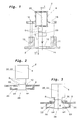
- Fig. 4 shows a fourth embodiment of the invention in which sensor 2 and sensor carrier 8 are mounted on a support arm 40.
- the sensor 2 can be mounted, for example, on the outside of a motor vehicle.
- the holding arm 40 is at least partially formed as a hollow profile and has at its end remote from the vehicle 42 on a transverse to the longitudinal direction of the support arm 40 extending sensor opening 44.
- the support arm 40 is enveloped by a first support arm cover 46 and a second support arm cover 47.
- the first holding arm cover 46 has a sensor holder opening 48 into which the sensor holder 8 is inserted.
- the sensor holder 8 has an annular circumferential, stepped collar 50 which engages overlapping in a corresponding annular circumferential step 52 in the first Gararmabdeckung 46.
- the stepped collar 50 and the corresponding step 52 are abutted, and on the outside they are spaced apart with a predefined gap s5. Again, the gap s5 can be adapted to external specifications.
- the sensor opening 44 in the hollow region of the holding arm 40 is bounded by a flat edge portion 54.
- screw holes 18 are provided.
- annular mounting collar 56 of the first Gararmabdeckung 46 extends.
- the mounting collar 56 also has screw holes 18.
- the left and right screw receivers 13 and 14 extend inwardly in the direction of the support arm 40.
- a flat edge portion 58 extends as a boundary of the sensor head opening 12.
- the edge portion 58 also has screw holes 18. From the sensor main body 4, laterally, left and right fastening tabs 15 and 16 extend, which are associated with the left and right screw seats 13 and 14. The two fastening tabs 15 and 16 lie on the inside on the flat edge portion 54.
- the sensor head 6 is seated in the sensor head opening 12, so that only a circumferential joint gap with gap s3 between the edge of the sensor head opening 12 and the sensor head 6 results.
- the plug edge or overlap connection between the annular collar 50 and the complementary annular step 52 is formed so as to provide an externally visible annular closed gap 62 having a predefined gap dimension s5.
- the left side of the annular collar 50 projects beyond the end of the sensor head 6 while the right side of the annular collar 50 is slightly recessed from the sensor head 6.
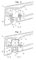
- Fig. 5 shows a fifth embodiment of the invention, which differs from the embodiment according to Fig. 4 characterized in that the sensor main body 4 has no attachment tabs.
- the sensor opening 44 in the holder arm 40 is dimensioned so that the sensor head 6 facing lower edge of the sensor main body 4 is seated on the flat edge portion 54.
- the remote from the sensor head 6 end of the sensor main body 4 is covered by an upper retaining cap or an upper headband 70, from the left and right fastening tabs 72 and 73 wegeruiten laterally.
- Fig. 6 shows a sixth embodiment of the invention, which differs from the embodiment according to Fig. 5 characterized in that the sensor main body 4 has no attachment tabs.
- the left and right screw receivers 13 and 14 are made to be spread inwardly so that the sensor head 6 facing lower edge of the sensor main body 4 is seated on the upper ends of the two screw receivers 13 and 14.
- the remote from the sensor head 6 other end sensor main body 4 abuts the inside of the holder arm 40, so that the sensor main body 4 and thus the sensor 2 between the inside of the support arm 40 and the top of the two screw receivers 13 and 14 is clamped.
- the fastening screws 60 pass through the screw holes 18 in the flat edge portion 54, the screw holes 18 in the annular mounting collar 56 and engage in the screw receptacles 15 and 16 a.
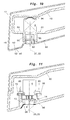
- Figure 7 shows a seventh embodiment of the invention, which differs from the embodiment according to Fig. 6 differs in that the sensor head 6 facing lower edge of the sensor main body 4 is not supported on widened screw receptacles 14 and 16, but that the sensor head 6 facing the lower side of the sensor main body 4 by a lower holding cap or a lower headband 80 is included. From the lower retaining cap 80, left and right attachment tabs 82 and 83 extend laterally. The sensor main body 4 and thus the sensor 2 are thus clamped between the lower holding cap 80 and the inside of the holding arm 40 and fixed to the holding arm 40.
- Fig. 8 shows an eighth embodiment of the invention, which differs from the embodiment Fig. 4 differs in that sensor holder 8 and first support arm cover 46 are integrally formed.
- the unnecessary in the embodiments according to the FIGS. 4 to 6 provided fastening collar 46.
- the fastening screws 60 pass through the screw holes of the fastening tabs 15 and 16, the screw holes 18 in the flat edge portion 54 and then engage in the two screw receptacles of 13 and 14 a.
- Fig. 9 shows a ninth embodiment of the invention, which differs from the previous embodiments, especially in that the sensor holder 8 has no screw receptacles.
- the flat edge portion 54 in the support arm 40 is provided with a cylindrical cap 90 which extends outwardly. Similarly, extends from the edge portion 58 of the sensor holder 8, a cylindrical cap 92 toward the sensor main body 4.
- the outer diameter of the cylindrical cap 92 corresponds to the inner diameter of the cylindrical cap 90.
- the upper end of the cylindrical cap 92 engages in the lower end of the cylindrical Attachment 90 and the cylindrical attachment 92 is clamped between the sensor head 6 and the cylindrical attachment 90.
- the underside of the sensor main body 4 facing the sensor head 6 sits, as in the embodiment according to FIG Fig.
- the remote from the sensor head 6 side of the sensor main body 4 is as in the embodiment according to Fig. 5 covered by an upper retaining cap 70, from which the two fastening straps 72 and 73 extend laterally away.
- the screw holes 18 in the flat edge portion 54 are threaded, so that the fastening screws 60 pass through the screw holes 18 in the fastening tabs 72 and 73 and are fixed in the screw threaded holes in the flat edge portion 54.
- Fig. 10 shows a tenth embodiment of the invention
- you move from the embodiment Fig. 9 differs in that the sensor main body 4 and thus the sensor 2 is clamped in the interior of the support arm 40.
- the sensor main body 4 sits with the lower edge facing the sensor head 6 again on the flat edge portion 54 and on the upper side of the sensor main body 4 or on the side remote from the sensor head 6 of the sensor main body, a spring element 94 is provided, which against the inside of the support arm 40 presses and fixes the sensor main body and thus the sensor 2 in the holding arm 40
- Fig. 11 shows an eleventh embodiment of the invention, which differs from the preceding embodiments in that the holding arm 40 itself is formed as a sensor holder 8 and that the sensor holder 8 is an integral part of the support arm 40.
- the holding arm 40 is formed at least in the region in which the sensor 2 is arranged as a hollow profile and has the sensor head opening 12.
- the sensor head 6 is fitted in the sensor head opening 12 with minimum clearance s3.
- From the sensor main body 4 extending left and right fastening tabs 13 and 14 away. Laterally from the sensor head opening 12, the left and right screw receivers 13 and 14 extend inwardly toward the sensor main body 4. Fixing screws 60 pass through the screw holes 18 in the two fastening straps 13 and 14 and engage in the two screw receptacles 13 and 14 and thus fix the sensor 2 in the holding arm 40.
- heating element 96 The part of the sensor head 6 lying in the interior of the holding arm 40 is enclosed annularly by a heating element 96.
- this heating element 96 condensate is prevented from precipitating on the externally accessible side of the sensor 2. Details of this heating element are from the German patent application DE 02014202664.4 to see. In this regard, here is fully to the DE 02014202664.4 Referenced. Of course, this heating element 96 can also be used in all the embodiments described above.
- the outer side of the holding arm 40 in the region of the sensor holder 8 is made dull or provided with a matt coating 98 in order to prevent reflections in the sensor. This is particularly important if the sensor 2 is a camera and the sensor head 6 is the lens of a camera.
- the coating 98 can also be provided in all other embodiments described above.
- screw receptacles are provided in the embodiments described above, there is always talk of two screw receptacles. Of course, only one or more than two screw receptacles can be provided.
- the sensor head 6 is inserted precisely into the sensor head opening 12 in the sensor holder 8.
- the sensor head 6 can also be inserted into the sensor head opening 12 by means of a clamping or press fit.
Landscapes
- Engineering & Computer Science (AREA)
- Mechanical Engineering (AREA)
- Physics & Mathematics (AREA)
- General Physics & Mathematics (AREA)
- Radar, Positioning & Navigation (AREA)
- Remote Sensing (AREA)
- Computer Networks & Wireless Communication (AREA)
- Geophysics And Detection Of Objects (AREA)
- Control Of Driving Devices And Active Controlling Of Vehicle (AREA)
- Standing Axle, Rod, Or Tube Structures Coupled By Welding, Adhesion, Or Deposition (AREA)
- Fittings On The Vehicle Exterior For Carrying Loads, And Devices For Holding Or Mounting Articles (AREA)
- Photometry And Measurement Of Optical Pulse Characteristics (AREA)
Abstract
Es wird Sensoranordnung, insbesondere für außen an einem Fahrzeug anzubringende Sensoren (2) zur Überwachung des Fahrzeugumfeldes bereitgestellt. Kleine Fertigungstoleranzen (t) zwischen dem Sensorkopf (6) und dem Sensorhauptkörper (4) können zu ungleichmäßigen Spaltmaßen (s1, s2) führen. Dadurch, dass die Sensorkopfaufnahme (10) so ausgebildet ist, dass im montierten Zustand des Sensors (2) im Sensorhalter (8) die Sensorhalteachse (24) und die Sensorachse (20) fluchten ergibt sich zwischen dem Rand der Sensorkopföffnung (12) und dem Sensorkopf (6) ein Fügespalt mit konstantem Spaltmaß (s3). Die optisch als unschön empfundenen Spaltmaßvariationen (s1, s2) werden dadurch verhindert bzw. es wird die optische Wertigkeit der Baugruppe erhöht. Das gleichmäßige Spaltmaß (s3) verringert auch Windgeräusche und Verschmutzungen im Innenbereich. Trotz des konstanten Spaltmaßes (s3) wird die Montage des Sensors (2) im Sensorhalter (8) nicht schwieriger. Die Außenseite des Sensorhalters (8) ist vorzugsweise als Sichtteil ausgestaltet. Alternativ ist jedoch auch eine zusätzliche durchsichtige Abdeckung möglich.It is sensor arrangement, in particular for externally mounted on a vehicle sensors (2) for monitoring the vehicle environment provided. Small manufacturing tolerances (t) between the sensor head (6) and the sensor main body (4) can lead to non-uniform gap dimensions (s1, s2). Characterized in that the sensor head receptacle (10) is formed so that in the mounted state of the sensor (2) in the sensor holder (8) the sensor holding axis (24) and the sensor axis (20) are aligned results between the edge of the sensor head opening (12) and the Sensor head (6) a joint gap with constant gap (s3). The optically perceived as unattractive Spaltmaßvariationen (s1, s2) are thereby prevented or it is the optical value of the assembly increases. The even gap (s3) also reduces wind noise and indoor pollution. Despite the constant gap (s3), mounting the sensor (2) in the sensor holder (8) will not be more difficult. The outside of the sensor holder (8) is preferably designed as a visible part. Alternatively, however, an additional transparent cover is possible.
Description
Die Erfindung betrifft eine Sensoranordnung, insbesondere für außen an einem Fahrzeug anzubringende Sensoren zur Überwachung des Fahrzeugumfeldes gemäß dem Oberbegriff des Anspruchs 1.The invention relates to a sensor arrangement, in particular for sensors to be mounted on the outside of a vehicle for monitoring the vehicle environment according to the preamble of
Bei Kraftfahrzeugen werden immer Sensoren unterschiedlichster Art für die Überwachung des Fahrzeugsumfeldes eingesetzt. Es kommen Ultraschallsensoren für Parkassistenzsysteme, Radarsensoren für Abstandsüberwachungssysteme, Kameras für indirekte Sichtsysteme und Wärmebildkameras zur Erfassung von Personen im Nahbereich um Fahrzeuge und dergleichen zum Einsatz.In motor vehicles sensors of various types are always used for monitoring the vehicle environment. Ultrasonic sensors for parking assistance systems, radar sensors for distance monitoring systems, cameras for indirect vision systems and thermal imaging cameras for detecting persons in close proximity to vehicles and the like are used.
Wie in
Der Sensor 2 umfasst eine Sensorachse 20 nach der er auszurichten ist. Der Sensorhauptkörper 4 umfasst eine Hauptkörpermittelachse 22, die aufgrund von Fertigungstoleranzen t von der Sensorachse 20 abweicht. Die Sensorkopfaufnahme 10 bzw. die Sensorkopföffnung 12 weisen eine Sensorhalteachse 24 auf. Da der Sensor 2 mittels der symmetrisch zum dem Sensorhauptkörper 4 angeordneten Befestigungslaschen 15 und 16 an dem Sensorträger montiert wird, muss die Fertigungstoleranz t zwischen Sensorachse 20 und Hauptkörpermittelachse bei der Dimensionierung der Sensorkopföffnung 12 berücksichtigt werden. Es ergeben sich daher im zusammengebauten Zustand von Sensor 2 und Sensorträger 8 zwischen dem Rand der Sensorkopföffnung 12 und dem Sensorkopf 6 unterschiedliche Spaltmaße zwischen s1 und s2. Diese unterschiedlichen Spaltmaße zwischen s1 und s2 führen zu einem optisch unbefriedigenden Ergebnis, da das menschliche Auge auf solche Spaltmaßvariationen empfindlich reagiert.The
Es ist daher Aufgabe der vorliegenden Erfindung eine Sensoranordnung anzugeben, die derartige Spaltmaßvariationen vermeidet.It is therefore an object of the present invention to provide a sensor arrangement which avoids such Spaltmaßvariationen.
Die Lösung dieser Aufgabe erfolgt durch die Merkmale des Anspruchs 1.The solution of this object is achieved by the features of
Dadurch, dass die Sensorkopfaufnahme so ausgebildet ist, dass im montierten Zustand des Sensors im Sensorhalter die Sensorhalteachse und die Sensorachse fluchten ergibt sich zwischen dem Rand der Sensorkopföffnung und dem Sensorkopf ein Fügespalt mit konstantem Spaltmaß. Die optisch als unschön empfundenen Spaltmaßvariationen werden dadurch verhindert bzw. es wird die optische Wertigkeit der Baugruppe erhöht. Das gleichmäßige Spaltmaß verringert auch Windgeräusche und Verschmutzungen im Innenbereich. Trotz des konstanten Spaltmaßes wird die Montage des Sensors im Sensorhalter nicht schwieriger. Die Außenseite des Sensorhalters ist vorzugsweise als Sichtteil ausgestaltet. Alternativ ist jedoch auch eine zusätzliche durchsichtige Abdeckung möglich. Die Befestigungsmittel können ein oder mehrere Schrauben, Klemmen und dergleichen umfassen.Characterized in that the sensor head receptacle is formed so that in the mounted state of the sensor in the sensor holder, the sensor holding axis and the sensor axis are aligned between the edge of the sensor head opening and the sensor head results in a joint gap with a constant gap. The optically perceived as unattractive Spaltmaßvariationen be prevented or it will increase the visual value of the assembly. The even gap size also reduces wind noise and indoor pollution. Despite the constant gap, the mounting of the sensor in the sensor holder is not difficult. The outside of the sensor holder is preferably designed as a visible part. Alternatively, however, an additional transparent cover is possible. The attachment means may comprise one or more screws, clamps and the like.
Vorzugsweise ist der Sensorkopf in der Sensorkopföffnung fixiert - Anspruch 2. Dies erfolgt entweder durch einen Klemmsitz des Sensorkopfes in der Sensorkopföffnung oder durch umlaufenden Kragen an dem Sensorkopf, der auf dem Sensorhalter aufliegt - Anspruch 3.This is done either by a clamping fit of the sensor head in the sensor head opening or by circumferential collar on the sensor head, which rests on the sensor holder -
Gemäß einer vorteilhaften Ausgestaltung ist die Sensorkopföffnung von einer Blende mit Blendenöffnung umgeben. Der Sensorkopf ragt durch die Sensorkopföffnung hindurch und in die Blendenöffnung hinein. Dadurch kann das von außen sichtbare Spaltmaß zwischen Sensorkopf und Rand der Blendenöffnung nach externen vorgaben festgelegt werden - Anspruch 4.According to an advantageous embodiment, the sensor head opening is surrounded by a diaphragm with an aperture. The sensor head protrudes through the sensor head opening through and into the aperture. As a result, the externally visible gap between the sensor head and the edge of the aperture can be set according to external specifications.
Durch das Vorsehen von Zentriermitteln an Sensorkopf und Sensoraufnahme wird sicher gewährleistet, dass Sensorachse und Sensorhalteachse miteinander fluchten - Anspruch 5.The provision of centering means on the sensor head and sensor receptacle ensures that the sensor axis and the sensor holding axis are aligned with one another -
Gemäß einer vorteilhaften Ausgestaltung nach Anspruch 6 werden die Fertigungstoleranzen zwischen der Hauptkörpermittelachse und der Sensorachse durch entsprechende Dimensionierung der Befestigungsmittel von außen unsichtbar ausgeglichen.According to an advantageous embodiment according to
Gemäß der vorteilhaften Ausgestaltung der Erfindung nach Anspruch 7 sind Sensor und Sensorhalter an oder in einem Haltearm befestigt.According to the advantageous embodiment of the invention according to claim 7 sensor and sensor holder are attached to or in a holding arm.
Durch die Ausgestaltungen nach den Ansprüchen 8 bis 12 haben die verschiedenen Möglichkeiten der Integration von Sensor und Sensorhalter in einen Haltearm zum Gegenstand.Due to the embodiments according to
Durch die vorteilhafte Ausgestaltung der Erfindung nach Anspruch 10 und 11 kann das Spaltmaß an externe Anforderungen angepasst werden. Zusätzlich wird die Länge des Spaltes mit vordefiniertem Spaltmaß vergrößert und dadurch optisch auffälliger gemacht.Due to the advantageous embodiment of the invention according to
Durch die die vorteilhafte Ausgestaltung nach Anspruch 13 kann der Sensorhalter, der Haltearm und/oder die Haltearmabdeckung als Kühlkörper für den Sensor 2 genutzt werden.Due to the advantageous embodiment according to
Durch die die vorteilhafte Ausgestaltung nach Anspruch 14 wird ein Beschlagen der von außen zugänglichen Sensorfläche verhindert, was insbesondere bei Kameras und deren Objektiven wichtig ist.By the advantageous embodiment according to claim 14 fogging of the externally accessible sensor surface is prevented, which is particularly important for cameras and their lenses.
Die vorteilhafte Ausgestaltung nach Anspruch 15 ermöglicht indirekte Sichtsysteme mit Spiegelersatzkameras um gesetzlich vorgeschrieben Sichtfelder zu erfassen. Die Sensorachse ist hierbei die optische Achse des Kameraobjektivs.The advantageous embodiment according to
Durch die vorteilhafte Ausgestaltung nach Anspruch 8 werden ungewünschte Reflexionen in den Sensor vermieden bzw. reduziert.Due to the advantageous embodiment according to claim 8 unwanted reflections are avoided or reduced in the sensor.
Die Sensoranordnung lässt sich vorzugsweise in bereits außen am Fahrzeug montierten Bauteilen, wie Blinkerleuchten, Außenspiegel und dergleichen integrieren - Anspruch 18The sensor arrangement can preferably be integrated in components already mounted on the outside of the vehicle, such as turn signal lights, exterior mirrors and the like -
Die übrigen Unteransprüche beziehen sich auf weitere vorteilhafte Ausgestaltung der Erfindung.The remaining subclaims relate to a further advantageous embodiment of the invention.
Weitere Einzelheiten, Merkmale und Vorteile der Erfindung ergeben sich aus der nachfolgenden Beschreibung bevorzugter Ausführungsformen anhand der Zeichnungen.Further details, features and advantages of the invention will become apparent from the following description of preferred embodiments with reference to the drawings.
Es zeigt:
-
Fig. 1 eine Explosionsdarstellung einer ersten Ausführungsform der Erfindung; -
Fig. 2 eine Explosionsdarstellung einer zweiten Ausführungsform der Erfindung; -
Fig. 3 eine schematische Darstellung einer dritten Ausführungsform der Erfindung; -
Fig. 4 eine schematische Darstellung einer vierten Ausführungsform der Erfindung; -
Fig. 5 eine Schnittdarstellung einer fünften Ausführungsform der Erfindung; -
Fig. 6 eine Schnittdarstellung einer sechsten Ausführungsform der Erfindung; -
Fig. 7 eine Schnittdarstellung einer siebten Ausführungsform der Erfindung; -
Fig. 8 eine Schnittdarstellung einer achten Ausführungsform der Erfindung; -
Fig. 9 eine Schnittdarstellung einer neunten Ausführungsform der Erfindung; -
Fig. 10 eine Schnittdarstellung einer zehnten Ausführungsform der Erfindung; -
Fig. 11 eine Schnittdarstellung einer elften Ausführungsform der Erfindung; und -
Fig. 12 eineFig. 1 entsprechende Darstellung einer Sensoranordnung nach dem Stand der Technik.
-
Fig. 1 an exploded view of a first embodiment of the invention; -
Fig. 2 an exploded view of a second embodiment of the invention; -
Fig. 3 a schematic representation of a third embodiment of the invention; -
Fig. 4 a schematic representation of a fourth embodiment of the invention; -
Fig. 5 a sectional view of a fifth embodiment of the invention; -
Fig. 6 a sectional view of a sixth embodiment of the invention; -
Fig. 7 a sectional view of a seventh embodiment of the invention; -
Fig. 8 a sectional view of an eighth embodiment of the invention; -
Fig. 9 a sectional view of a ninth embodiment of the invention; -
Fig. 10 a sectional view of a tenth embodiment of the invention; -
Fig. 11 a sectional view of an eleventh embodiment of the invention; and -
Fig. 12 aFig. 1 corresponding representation of a sensor arrangement according to the prior art.
Bei den nachfolgend beschriebenen beispielhaften Ausführungsformen der Erfindung werden einander entsprechende Teile mit gleichen Bezugszeichen bezeichnet.In the exemplary embodiments of the invention described below, corresponding parts are designated by the same reference numerals.
Der Sensor 2 umfasst eine Sensorachse 20 nach der er auszurichten ist. Der Sensorhauptkörper 4 umfasst eine Hauptkörpermittelachse 22, die auf Grund von Fertigungstoleranzen t von der Sensorachse 20 abweicht bzw. abweichen kann. Die Sensorkopfaufnahme 10 bzw. die Sensorkopföffnung 12 weisen eine Sensorhalterachse 24 auf. Im Gegensatz zu dem Stand der Technik gemäß
Die Fertigungstoleranz t ist in den nachfolgend beschriebenen Ausführungsformen aus Gründen der einfacheren Darstellung nicht mehr zeichnerisch dargestellt.The manufacturing tolerance t is no longer shown in the drawings described below for reasons of simplicity of illustration.
Der Sensorhalter 8 weist einen ringförmig umlaufenden, stufenförmigen Kragen 50 auf, der überlappend in eine korrespondierende ringförmig umlaufende Stufe 52 in der ersten Haltearmabdeckung 46 eingreift. Auf der Innenseite sind der stufenförmige Kragen 50 und die korrespondierende Stufe 52 auf Stoß gelegt und an der Außenseite sind sie mit einem vordefiniertem Spaltmaß s5 beabstandet. Wiederum kann das Spaltmaß s5 an externe Vorgaben angepasst werden.The
Die Sensoröffnung 44 im Hohlbereich des Haltearms 40 wird durch einen ebenen Randabschnitt 54 begrenzt. In dem Randabschnitt 54 sind Schraublöcher 18 vorgesehen. Entlang der Außenseite der ebenen Randabschnitte 54 des Haltearms 40 erstreckt sich ein ringförmiger Befestigungskragen 56 der ersten Haltearmabdeckung 46. Der Befestigungskragen 56 weist ebenfalls Schraublöcher 18 auf. Innerhalb des ringförmigen Kragens 50 erstrecken sich die linke und rechte Schraubenaufnahme 13 und 14 nach innen in Richtung Haltearm 40. Zwischen den beiden Schraubenaufnahmen 13 und 14 erstreckt sich ein ebener Randabschnitt 58 als Begrenzung der Sensorkopföffnung 12. Der Randabschnitt 58 weist ebenfalls Schraublöcher 18 auf. Von dem Sensorhauptkörper 4 erstrecken sich seitlich eine linke und eine rechte Befestigungslasche 15 und 16 weg, die der linken und rechten Schraubenaufnahme 13 und 14 zugeordnet sind. Die beiden Befestigungslaschen 15 und 16 liegen auf der Innenseite auf dem ebenen Randabschnitt 54 auf.The
Zwei Befestigungsschrauben 60 durchsetzten zunächst die Schraublöcher 18 in den Befestigungslaschen 15 und 16, dann die Schraublöcher 18 dem ebenen Randabschnitt 54 des Haltearms 40, die Schraublöcher 18 in dem Befestigungskragen 56 und greifen schließlich in die Schraubenaufnahmen 13 und 14 ein. Damit ist der Sensor 2, der Sensorhalter 8 und die erste Haltearmabdeckung 40 miteinander und am Haltearm 40 fixiert. Die einzelnen Bauteile sind so dimensioniert, dass der Sensorkopf 6 in etwa mit der Außenseite der Sensorkopföffnung 12 fluchtet.Two fastening screws 60 penetrated first through the screw holes 18 in the
Der Sensorkopf 6 sitzt in der Sensorkopföffnung 12, so dass sich lediglich ein umlaufende Fügespalt mit Spaltmaß s3 zwischen den Rand der Sensorkopföffnung 12 und den Sensorkopf 6 ergibt. Die Steckrand- oder Überlappverbindung zwischen dem ringförmigen Kragen 50 und der komplementären ringförmigen Stufe 52 ist so ausgebildet, dass sich ein von außen sichtbarer ringförmiger geschlossener Spalt 62 mit einem vordefinierten Spaltmaß s5 ergibt.The
Die linke Seite des ringförmigen Kragens 50 ragt über das Ende des Sensorkopfes 6 hinaus während die rechte Seite des ringförmigen Kragens 50 gegenüber den Sensorkopf 6 etwas zurückgesetzt ist. Durch diese Ausgestaltung wird ein optisch gleichmäßiger Eindruck erreicht und außerdem wird die Gefahr der Verschmutzung durch seitlichen Eintrag vermindert.The left side of the
Der im Inneren des Haltearms 40 liegende Teil des Sensorkopfs 6 ist mit einem Heizelement 96 ringförmig umschlossen. Durch dieses Heizelement 96 wird verhindert, dass sich Kondensat auf der von außen zugänglichen Seite des Sensors 2 niederschlägt. Einzelheiten zu diesem Heizelement sind aus der deutschen Patentanmeldung
Zusätzlich ist die Außenseite des Haltearms 40 im Bereich des Sensorhalters 8 matt ausgeführt bzw. mit einer matten Beschichtung 98 versehen, um Reflexionen in dem Sensor zu verhindern. Dies ist insbesondere dann wichtig, wenn es sich bei dem Sensor 2 um eine Kamera und bei dem Sensorkopf 6 um das Objektiv einer Kamera handelt. Die Beschichtung 98 kann natürlich auch bei allen anderen vorstehenden beschriebenen Ausführungsformen vorgesehen werden.In addition, the outer side of the holding
Sofern in den vorstehend beschriebenen Ausführungsformen Schraubenaufnahmen vorgesehen sind, ist immer von zwei Schraubenaufnahmen die Rede. Es können natürlich auch nur eine oder mehr als zwei Schraubenaufnahmen vorgesehen werden.If screw receptacles are provided in the embodiments described above, there is always talk of two screw receptacles. Of course, only one or more than two screw receptacles can be provided.
Bei den vorstehend beschriebenen Ausführungsformen ist der Sensorkopf 6 passgenau in die Sensorkopföffnung 12 im Sensorhalter 8 eingefügt. Der Sensorkopf 6 kann auch mittels Klemm- oder Presssitz in die Sensorkopföffnung 12 eingefügt sein.In the embodiments described above, the
- s1, s2, s3, s4, s5s1, s2, s3, s4, s5
- Spaltmaßclearance
- tt
- Fertigungstoleranz, Abweichung zwischen 22 und 20Manufacturing tolerance, deviation between 22 and 20
- 22
- Sensorsensor
- 44
- SensorhauptkörperSensor main body
- 66
- Sensorkopfsensor head
- 88th
- Sensorhaltersensor holder
- 1010
- SensorkopfaufnahmeSensor head mounting
- 1212
- SensorkopföffnungSensor head opening
- 1313
- linke Schraubenaufnahmeleft screw holder
- 1414
- rechte Schraubenaufnahmeright screw holder
- 1515
- linke Befestigungslascheleft fastening tab
- 1616
- rechte Befestigungslascheright fastening strap
- 1818
- Schraublöcherscrew
- 2020
- Sensorachsesensor axis
- 2222
- HauptkörpermittelachseMain body central axis
- 2424
- SensorhalteachseSensor support axis
- 2626
- Blendecover
- 2828
- Blendenöffnungaperture
- 3030
- SensorkopfkragenSensor head collar
- 3232
- Ringwulsttorus
- 3434
- Ringnutring groove
- 4040
- Haltearmholding arm
- 4242
- vom Fahrzeug abgewandtes Ende von 40away from the vehicle end of 40
- 4444
- Sensoröffnung in 40Sensor opening in 40
- 4646
- erste Haltearmabdeckungfirst retaining arm cover
- 4747
- zweite Haltearmabdeckungsecond retaining arm cover
- 4848
- Sensorhalteröffnung in 46Sensor holder opening in 46
- 5050
- ringförmig umlaufender, stufenförmiger Kragen an 8ring-shaped circumferential, stepped collar on 8
- 5252
- ringförmige Stufe in 46annular step in FIG. 46
- 5454
- ebener Randabschnitt um 44flat edge section around 44
- 5656
- ringförmiger Befestigungskragen an 46annular fastening collar on 46
- 5858
- ebener Randabschnitt um 12flat edge section around 12
- 6060
- Befestigungsschraubenmounting screws
- 6262
- ringförmiger Spalt um 8annular gap around 8
- 7070
- obere Haltekappe oder oberer Haltebügelupper retaining cap or upper retaining bracket
- 7272
- linke Befestigungslascheleft fastening tab
- 7373
- rechte Befestigungslascheright fastening strap
- 8080
- untere Haltekappe oder unterer Haltebügellower retaining cap or lower retaining bracket
- 8282
- linke Befestigungslascheleft fastening tab
- 8383
- rechte Befestigungslascheright fastening strap
- 9090
- zylindrischer Aufsatz auf 50cylindrical attachment on 50
- 9292
- zylindrischer Aufsatz auf 58cylindrical attachment on 58
- 9494
- Federelementspring element
- 9696
- Heizelementheating element
- 9898
- Beschichtungcoating
Claims (19)
wobei der Sensorkopf (6) eine Sensorachse (20) aufweist nach der die Sensoranordnung auszurichten ist,
einem Sensorhalter (8), der eine Sensorkopfaufnahme (10) mit einer Sensorkopföffnung (12) aufweist in die der Sensorkopf (6) hineinragt,
wobei die Sensorkopfaufnahme (10) eine Sensorhalteachse (24) festlegt, und einem Befestigungsmittel (13, 14,18, 60, 94) zur Befestigung des Sensors (2) im Sensorträger (8), dadurch gekennzeichnet,
dass die Sensorkopfaufnahme (10) so ausgebildet ist, dass im montierten Zustand des Sensors (2) im Sensorhalter (8) die Sensorhalteachse (24) und die Sensorachse (20) fluchten.Sensor arrangement, in particular for sensors to be mounted on the outside of a motor vehicle for monitoring the vehicle environment, having a sensor (2) comprising a sensor main body (4) and a sensor head (6),
wherein the sensor head (6) has a sensor axis (20) after which the sensor arrangement is to be aligned,
a sensor holder (8) having a sensor head receptacle (10) with a sensor head opening (12) into which the sensor head (6) protrudes,
wherein the sensor head receptacle (10) defines a sensor holding axis (24), and a fastening means (13, 14, 18, 60, 94) for fastening the sensor (2) in the sensor carrier (8), characterized
that the sensor head holder (10) is formed so that in the assembled state of the sensor (2) in the sensor holder (8) are aligned with the sensor support axis (24) and the sensor axis (20).
dass der Sensorkopf (6) einen Sensorkopfkragen (30) aufweist, der symmetrisch zur Sensorachse (20) angeordnet ist und der auf dem Sensorhalter (8) aufliegt.Sensor arrangement according to claim 2, characterized
that the sensor head (6) has a sensor head collar (30) which is arranged symmetrically to the sensor axis (20) and the sensor on the holder (8) rests.
dass der Sensorkopf (6) über die Sensorkopföffnung (12) hinausragt,
dass die Sensorkopföffnung (12) von einer Blende (26) mit einer Blendenöffnung (28) umgeben ist,
dass der Sensorkopf (6) in die Blendenöffnung (28) hineinragt, und
dass die Blendenöffnung (28) zu dem Sensorkopf (6) ein vordefiniertes Spaltmaß (s4) festlegt.Sensor arrangement according to Claim 1 or 2, characterized
that the sensor head (6) on the sensor head opening (12) protrudes,
that the sensor head opening (12) of a diaphragm (26) having an aperture (28) is surrounded,
that the sensor head (6) projects into the diaphragm opening (28), and
that the aperture (28) to the sensor head (6) a pre-defined gap dimension (s4).
dass der Sensorhauptkörper (4) eine Hauptkörpermittelachse (22) aufweist, und dass die Befestigungsmittel (18, 60) Abweichungen zwischen Hauptkörpermittelachse (24) und Sensorachse (20) ausgleichen.Sensor arrangement according to one of the preceding claims, characterized
in that the sensor main body (4) has a main body central axis (22), and in that the fastening means (18, 60) compensate deviations between the main body central axis (24) and the sensor axis (20).
Applications Claiming Priority (1)
| Application Number | Priority Date | Filing Date | Title |
|---|---|---|---|
| DE102014205505.9A DE102014205505B4 (en) | 2014-03-25 | 2014-03-25 | SENSOR ARRANGEMENT |
Publications (2)
| Publication Number | Publication Date |
|---|---|
| EP2924398A2 true EP2924398A2 (en) | 2015-09-30 |
| EP2924398A3 EP2924398A3 (en) | 2015-12-16 |
Family
ID=52692561
Family Applications (1)
| Application Number | Title | Priority Date | Filing Date |
|---|---|---|---|
| EP15160357.8A Ceased EP2924398A3 (en) | 2014-03-25 | 2015-03-23 | Sensor assembly |
Country Status (4)
| Country | Link |
|---|---|
| US (1) | US10160401B2 (en) |
| EP (1) | EP2924398A3 (en) |
| JP (1) | JP6378638B2 (en) |
| DE (1) | DE102014205505B4 (en) |
Cited By (5)
| Publication number | Priority date | Publication date | Assignee | Title |
|---|---|---|---|---|
| WO2017076554A1 (en) * | 2015-11-04 | 2017-05-11 | Magna Mirrors Holding Gmbh | Camera module |
| EP3258289A1 (en) * | 2016-06-13 | 2017-12-20 | Robert Bosch GmbH | Method for attaching a holder for one sensor on a cladding for a means of locomotion |
| CN113978377A (en) * | 2021-10-26 | 2022-01-28 | 苏州驰昶金属制品有限公司 | Automobile detector base convenient to disassemble and assemble |
| US11400870B2 (en) * | 2018-11-26 | 2022-08-02 | Motherson Innovations Company Limited | Sensor receptacle for receiving a sensor of a motor vehicle and a trim component of a motor vehicle with such sensor receptacle |
| EP4180275A1 (en) | 2021-11-10 | 2023-05-17 | FICOSA International GmbH | Vehicle front camera arrangement |
Families Citing this family (15)
| Publication number | Priority date | Publication date | Assignee | Title |
|---|---|---|---|---|
| EP3194853B1 (en) * | 2014-09-03 | 2018-07-11 | Electrolux Appliances Aktiebolag | Domestic appliance, in particular cooking oven, with a camera |
| JP6202028B2 (en) * | 2015-03-24 | 2017-09-27 | トヨタ自動車株式会社 | Arrangement structure of surrounding information detection sensor and autonomous driving vehicle |
| US10144424B2 (en) | 2015-04-09 | 2018-12-04 | Toyota Jidosha Kabushiki Kaisha | Arrangement structure for vicinity information detection sensor |
| US9304386B1 (en) * | 2015-08-17 | 2016-04-05 | Ford Global Technologies, Llc | Seal ring for pickup truck box camera in center high mount stop lamp |
| DE102016107545A1 (en) * | 2016-04-22 | 2017-10-26 | SMR Patents S.à.r.l. | Heating device for a camera lens |
| KR102143048B1 (en) * | 2017-12-14 | 2020-08-10 | (주)엘지하우시스 | Holder fixing jig |
| DE102018202205A1 (en) * | 2018-02-13 | 2019-08-14 | Conti Temic Microelectronic Gmbh | Telecamera for a vehicle and attachment of a telecamera on the vehicle |
| DE102018103118B4 (en) | 2018-02-13 | 2024-03-14 | Valeo Schalter Und Sensoren Gmbh | Holding device for at least one ultrasonic sensor for installation on a wheel arch liner, a holding element being formed in one piece, module, arrangement, method |
| JP6988549B2 (en) * | 2018-02-20 | 2022-01-05 | トヨタ自動車株式会社 | Sensor module mounting structure |
| DE102018203502B4 (en) | 2018-03-08 | 2023-11-16 | Magna Exteriors Gmbh | Motor vehicle component with sensor holder and method for assembly |
| US10794735B2 (en) * | 2018-08-09 | 2020-10-06 | Ford Global Technologies, Llc | Pressurized sensor seal |
| CN110673149A (en) * | 2019-10-22 | 2020-01-10 | 江苏理工学院 | Radar range finding alarm device for assisting driving based on electric automobile |
| US11230234B1 (en) * | 2020-05-18 | 2022-01-25 | Waymo Llc | Compliant camera mounting |
| DE102020004639A1 (en) | 2020-07-30 | 2022-02-03 | A. Raymond Et Cie | Roof hood part of a driver's cab of a truck, driver's cab of a truck and method for fastening a housing of a functional part, in particular a lamp, to a base body of a roof hood part |
| DE102022132681A1 (en) | 2022-12-08 | 2024-06-13 | Hochschule Mannheim, Körperschaft des öffentlichen Rechts | Freezing aid device, corresponding manufacturing method and method for preparing a sample |
Family Cites Families (28)
| Publication number | Priority date | Publication date | Assignee | Title |
|---|---|---|---|---|
| DE7509304U (en) * | 1974-10-10 | 1975-09-25 | Jenaer Glaswerk Schott & Gen | Slide-in holder for measuring probe |
| AT376804B (en) * | 1980-12-17 | 1985-01-10 | Vogelbusch Gmbh | PROBE FOR MEASURING VOLATILE COMPONENTS OF A CULTURAL MEDIUM OF THE FERMENTATION INDUSTRY |
| IT214173Z2 (en) * | 1988-02-19 | 1990-04-02 | Magneti Marelli Spa | ASTIFORM ASSEMBLY BUSHING PARTICULARLY FOR AN ELECTROMAGNETIC SENSOR |
| DE19719519A1 (en) | 1997-05-09 | 1998-11-12 | Bosch Gmbh Robert | Arrangement with a module for installation in a bumper of a motor vehicle |
| US6172613B1 (en) * | 1998-02-18 | 2001-01-09 | Donnelly Corporation | Rearview mirror assembly incorporating vehicle information display |
| DE19752921A1 (en) | 1997-11-28 | 1999-06-02 | Bosch Gmbh Robert | Ultrasonic sensor for distance measurement onboard automobile |
| JP2001208763A (en) * | 1999-11-15 | 2001-08-03 | Nsk Ltd | Rolling bearing unit with rotational speed detector |
| US6463818B1 (en) * | 2000-04-04 | 2002-10-15 | International Truck Intellectual Property Company, L.L.C. | High retention force anti-lock brake sensor clip |
| US6641189B2 (en) * | 2001-03-16 | 2003-11-04 | Phd, Inc. | Article sensor assembly |
| US6909376B2 (en) | 2002-03-14 | 2005-06-21 | Mark Rennick | Integrated vehicle light and object proximity sensor assembly |
| JP4088100B2 (en) | 2002-05-14 | 2008-05-21 | 株式会社村上開明堂 | Rearview mirror with built-in camera |
| US6742395B1 (en) * | 2002-12-20 | 2004-06-01 | Texas Instruments Incorporated | Hermetic pressure transducer |
| JP4227550B2 (en) * | 2004-03-29 | 2009-02-18 | 長野計器株式会社 | Pressure sensor and manufacturing method thereof |
| DE102007024230A1 (en) * | 2007-05-21 | 2008-11-27 | Omron Electronics Mfg. Of Germany Gmbh | Holding part for mounting a sensor |
| GB2450710B (en) | 2007-07-04 | 2012-01-11 | Land Rover Uk Ltd | Vision assistance modules for vehicles |
| ITMI20080139U1 (en) | 2008-04-16 | 2009-10-17 | Cobra Automotive Technologies Spa | MODULAR DEVICE FOR THE PAIRING OF A TRANSDUCER TO A BUMPER |
| DE202008007404U1 (en) * | 2008-06-03 | 2008-09-18 | Morgenbesser, Karl | Measuring device for determining the characteristic of a built-in position encoder on a machine |
| EP2136192B1 (en) * | 2008-06-17 | 2012-08-01 | Hamilton Bonaduz AG | Sensor fixing assembly |
| DE102009028663B4 (en) | 2008-08-19 | 2018-03-15 | Ifm Electronic Gmbh | Measuring instrument for process measuring technology |
| DE102009028662B4 (en) | 2008-08-19 | 2014-11-20 | Ifm Electronic Gmbh | Arrangement for connecting a measuring device with a container containing the medium to be measured |
| DE102008054000B4 (en) * | 2008-10-30 | 2013-11-07 | Knorr-Bremse Systeme für Nutzfahrzeuge GmbH | Self-aligning apparatus and method of arranging a pulse speed sensor with respect to a rotor |
| WO2011141534A1 (en) | 2010-05-12 | 2011-11-17 | Ifm Electronic Gmbh | Assembly for connecting a measuring instrument to a container containing the medium to be measured |
| DE102010062772A1 (en) * | 2010-12-09 | 2012-06-14 | Ifm Electronic Gmbh | Sensor housing for inductive proximity switch utilized for e.g. automotive industry, has casing and plug sections comprising different cross-sections and formed as single-piece from round kneading part by using mandrel |
| DE202010016488U1 (en) * | 2010-12-11 | 2011-02-17 | Sontec Sensorbau Gmbh | Sensor Process adapter |
| DE102011017535A1 (en) | 2011-04-26 | 2012-10-31 | Endress + Hauser Conducta Gesellschaft für Mess- und Regeltechnik mbH + Co. KG | Probe device for measuring a measured variable of a process medium contained in a process container |
| DE102013000204A1 (en) * | 2013-01-08 | 2014-07-24 | Wabco Gmbh | Sensor device for measuring speed on a wheel of a vehicle, brake system for a vehicle and vehicle therewith and use of the sensor device for measuring speed on a wheel of a vehicle |
| DE102013020894B3 (en) * | 2013-12-11 | 2015-04-09 | Mekra Lang Gmbh & Co. Kg | Camera with heating element |
| DE102013021622A1 (en) * | 2013-12-18 | 2015-07-02 | Mekra Lang Gmbh & Co. Kg | Camera for vehicle, in particular commercial vehicle |
-
2014
- 2014-03-25 DE DE102014205505.9A patent/DE102014205505B4/en not_active Revoked
-
2015
- 2015-03-17 US US14/659,621 patent/US10160401B2/en active Active
- 2015-03-18 JP JP2015054111A patent/JP6378638B2/en not_active Expired - Fee Related
- 2015-03-23 EP EP15160357.8A patent/EP2924398A3/en not_active Ceased
Cited By (5)
| Publication number | Priority date | Publication date | Assignee | Title |
|---|---|---|---|---|
| WO2017076554A1 (en) * | 2015-11-04 | 2017-05-11 | Magna Mirrors Holding Gmbh | Camera module |
| EP3258289A1 (en) * | 2016-06-13 | 2017-12-20 | Robert Bosch GmbH | Method for attaching a holder for one sensor on a cladding for a means of locomotion |
| US11400870B2 (en) * | 2018-11-26 | 2022-08-02 | Motherson Innovations Company Limited | Sensor receptacle for receiving a sensor of a motor vehicle and a trim component of a motor vehicle with such sensor receptacle |
| CN113978377A (en) * | 2021-10-26 | 2022-01-28 | 苏州驰昶金属制品有限公司 | Automobile detector base convenient to disassemble and assemble |
| EP4180275A1 (en) | 2021-11-10 | 2023-05-17 | FICOSA International GmbH | Vehicle front camera arrangement |
Also Published As
| Publication number | Publication date |
|---|---|
| DE102014205505A1 (en) | 2015-10-01 |
| JP2015186994A (en) | 2015-10-29 |
| DE102014205505B4 (en) | 2019-05-16 |
| US10160401B2 (en) | 2018-12-25 |
| JP6378638B2 (en) | 2018-08-22 |
| EP2924398A3 (en) | 2015-12-16 |
| US20150274091A1 (en) | 2015-10-01 |
Similar Documents
| Publication | Publication Date | Title |
|---|---|---|
| DE102014205505B4 (en) | SENSOR ARRANGEMENT | |
| DE19724246B4 (en) | Adjustment device for a lens of a CCTV camera | |
| EP0915326A1 (en) | Method of manufacturing a pressure transducer and pressure transducer | |
| WO2001036903A1 (en) | Measuring rope-path sensor | |
| EP0031409A2 (en) | Insertable connection device with snap lock | |
| AT396815B (en) | FITTING FOR A THERMOSTAT VALVE | |
| DE102016207868A1 (en) | Mounting module for a vehicle light | |
| DE102007048298A1 (en) | fastening device | |
| DE102005053002B4 (en) | Exterior mirrors for motor vehicles, in particular for commercial vehicles | |
| EP3365199B1 (en) | Camera module | |
| EP2560038B1 (en) | Holder for optical element and assembly method | |
| DE3852351T2 (en) | Motor vehicle headlights. | |
| DE102022119405A1 (en) | Projection device for a means of transport | |
| EP3538777B1 (en) | Adjusting device | |
| DE102018202205A1 (en) | Telecamera for a vehicle and attachment of a telecamera on the vehicle | |
| DE19520502A1 (en) | Car photography lamp holder | |
| DE1276476B (en) | Storage of a threaded spindle for motor vehicle steering | |
| EP3497002B1 (en) | Tolerance compensation frame around head beam | |
| DE102010010405A1 (en) | Optical device and method for aligning and fixing the optical device | |
| DE102014220557A1 (en) | environment camera | |
| DE202018100034U1 (en) | Holder for attaching accessories to a vehicle handlebar | |
| DE102014211832A1 (en) | Holder for a lens and an image sensor, lens, imager module, camera and driver assistance system | |
| DE29810760U1 (en) | Observation facility | |
| DE20110716U1 (en) | Device for fastening a sensor | |
| DE2209541B2 (en) | Headlights for automobiles |
Legal Events
| Date | Code | Title | Description |
|---|---|---|---|
| PUAI | Public reference made under article 153(3) epc to a published international application that has entered the european phase |
Free format text: ORIGINAL CODE: 0009012 |
|
| AK | Designated contracting states |
Kind code of ref document: A2 Designated state(s): AL AT BE BG CH CY CZ DE DK EE ES FI FR GB GR HR HU IE IS IT LI LT LU LV MC MK MT NL NO PL PT RO RS SE SI SK SM TR |
|
| AX | Request for extension of the european patent |
Extension state: BA ME |
|
| PUAL | Search report despatched |
Free format text: ORIGINAL CODE: 0009013 |
|
| AK | Designated contracting states |
Kind code of ref document: A3 Designated state(s): AL AT BE BG CH CY CZ DE DK EE ES FI FR GB GR HR HU IE IS IT LI LT LU LV MC MK MT NL NO PL PT RO RS SE SI SK SM TR |
|
| AX | Request for extension of the european patent |
Extension state: BA ME |
|
| RIC1 | Information provided on ipc code assigned before grant |
Ipc: G01S 7/521 20060101ALI20151112BHEP Ipc: G01D 11/30 20060101AFI20151112BHEP Ipc: B60Q 1/00 20060101ALI20151112BHEP |
|
| 17P | Request for examination filed |
Effective date: 20160616 |
|
| RBV | Designated contracting states (corrected) |
Designated state(s): AL AT BE BG CH CY CZ DE DK EE ES FI FR GB GR HR HU IE IS IT LI LT LU LV MC MK MT NL NO PL PT RO RS SE SI SK SM TR |
|
| STAA | Information on the status of an ep patent application or granted ep patent |
Free format text: STATUS: REQUEST FOR EXAMINATION WAS MADE |
|
| R17P | Request for examination filed (corrected) |
Effective date: 20160616 |
|
| RIN1 | Information on inventor provided before grant (corrected) |
Inventor name: LANG, DR. WERNER Inventor name: DEFFNER, SIMON Inventor name: ZINK, MATTHIAS Inventor name: FINKENBERGER, ELMAR |
|
| RIN1 | Information on inventor provided before grant (corrected) |
Inventor name: DEFFNER, SIMON Inventor name: ZINK, MATTHIAS Inventor name: LANG, WERNER DR. Inventor name: FINKENBERGER, ELMAR |
|
| STAA | Information on the status of an ep patent application or granted ep patent |
Free format text: STATUS: EXAMINATION IS IN PROGRESS |
|
| 17Q | First examination report despatched |
Effective date: 20190411 |
|
| STAA | Information on the status of an ep patent application or granted ep patent |
Free format text: STATUS: EXAMINATION IS IN PROGRESS |
|
| STAA | Information on the status of an ep patent application or granted ep patent |
Free format text: STATUS: EXAMINATION IS IN PROGRESS |
|
| STAA | Information on the status of an ep patent application or granted ep patent |
Free format text: STATUS: THE APPLICATION HAS BEEN REFUSED |
|
| 18R | Application refused |
Effective date: 20220206 |