EP2924295A1 - Rotary compressor - Google Patents
Rotary compressor Download PDFInfo
- Publication number
- EP2924295A1 EP2924295A1 EP15161483.1A EP15161483A EP2924295A1 EP 2924295 A1 EP2924295 A1 EP 2924295A1 EP 15161483 A EP15161483 A EP 15161483A EP 2924295 A1 EP2924295 A1 EP 2924295A1
- Authority
- EP
- European Patent Office
- Prior art keywords
- refrigerant
- pipe
- accumulator
- opening
- sealing member
- Prior art date
- Legal status (The legal status is an assumption and is not a legal conclusion. Google has not performed a legal analysis and makes no representation as to the accuracy of the status listed.)
- Granted
Links
- 239000003507 refrigerant Substances 0.000 claims abstract description 221
- 238000002347 injection Methods 0.000 claims abstract description 71
- 239000007924 injection Substances 0.000 claims abstract description 71
- 230000006835 compression Effects 0.000 claims abstract description 49
- 238000007906 compression Methods 0.000 claims abstract description 49
- 239000007788 liquid Substances 0.000 claims abstract description 39
- 238000007789 sealing Methods 0.000 claims description 39
- 238000000926 separation method Methods 0.000 claims description 20
- 230000002093 peripheral effect Effects 0.000 claims description 7
- 238000010438 heat treatment Methods 0.000 description 13
- 239000003570 air Substances 0.000 description 6
- 239000012080 ambient air Substances 0.000 description 6
- 230000000694 effects Effects 0.000 description 6
- 238000000034 method Methods 0.000 description 6
- 238000005057 refrigeration Methods 0.000 description 6
- 238000001816 cooling Methods 0.000 description 3
- 230000003068 static effect Effects 0.000 description 3
- 239000000126 substance Substances 0.000 description 3
- RYGMFSIKBFXOCR-UHFFFAOYSA-N Copper Chemical compound [Cu] RYGMFSIKBFXOCR-UHFFFAOYSA-N 0.000 description 2
- 238000007664 blowing Methods 0.000 description 2
- 238000007796 conventional method Methods 0.000 description 2
- 229910052802 copper Inorganic materials 0.000 description 2
- 239000010949 copper Substances 0.000 description 2
- 239000000463 material Substances 0.000 description 2
- 238000000638 solvent extraction Methods 0.000 description 2
- 238000012986 modification Methods 0.000 description 1
- 230000004048 modification Effects 0.000 description 1
- 238000011144 upstream manufacturing Methods 0.000 description 1
Images


Classifications
-
- F—MECHANICAL ENGINEERING; LIGHTING; HEATING; WEAPONS; BLASTING
- F04—POSITIVE - DISPLACEMENT MACHINES FOR LIQUIDS; PUMPS FOR LIQUIDS OR ELASTIC FLUIDS
- F04C—ROTARY-PISTON, OR OSCILLATING-PISTON, POSITIVE-DISPLACEMENT MACHINES FOR LIQUIDS; ROTARY-PISTON, OR OSCILLATING-PISTON, POSITIVE-DISPLACEMENT PUMPS
- F04C23/00—Combinations of two or more pumps, each being of rotary-piston or oscillating-piston type, specially adapted for elastic fluids; Pumping installations specially adapted for elastic fluids; Multi-stage pumps specially adapted for elastic fluids
- F04C23/008—Hermetic pumps
-
- F—MECHANICAL ENGINEERING; LIGHTING; HEATING; WEAPONS; BLASTING
- F04—POSITIVE - DISPLACEMENT MACHINES FOR LIQUIDS; PUMPS FOR LIQUIDS OR ELASTIC FLUIDS
- F04C—ROTARY-PISTON, OR OSCILLATING-PISTON, POSITIVE-DISPLACEMENT MACHINES FOR LIQUIDS; ROTARY-PISTON, OR OSCILLATING-PISTON, POSITIVE-DISPLACEMENT PUMPS
- F04C18/00—Rotary-piston pumps specially adapted for elastic fluids
- F04C18/30—Rotary-piston pumps specially adapted for elastic fluids having the characteristics covered by two or more of groups F04C18/02, F04C18/08, F04C18/22, F04C18/24, F04C18/48, or having the characteristics covered by one of these groups together with some other type of movement between co-operating members
- F04C18/34—Rotary-piston pumps specially adapted for elastic fluids having the characteristics covered by two or more of groups F04C18/02, F04C18/08, F04C18/22, F04C18/24, F04C18/48, or having the characteristics covered by one of these groups together with some other type of movement between co-operating members having the movement defined in group F04C18/08 or F04C18/22 and relative reciprocation between the co-operating members
-
- F—MECHANICAL ENGINEERING; LIGHTING; HEATING; WEAPONS; BLASTING
- F04—POSITIVE - DISPLACEMENT MACHINES FOR LIQUIDS; PUMPS FOR LIQUIDS OR ELASTIC FLUIDS
- F04C—ROTARY-PISTON, OR OSCILLATING-PISTON, POSITIVE-DISPLACEMENT MACHINES FOR LIQUIDS; ROTARY-PISTON, OR OSCILLATING-PISTON, POSITIVE-DISPLACEMENT PUMPS
- F04C29/00—Component parts, details or accessories of pumps or pumping installations, not provided for in groups F04C18/00 - F04C28/00
- F04C29/0042—Driving elements, brakes, couplings, transmissions specially adapted for pumps
- F04C29/0085—Prime movers
-
- F—MECHANICAL ENGINEERING; LIGHTING; HEATING; WEAPONS; BLASTING
- F04—POSITIVE - DISPLACEMENT MACHINES FOR LIQUIDS; PUMPS FOR LIQUIDS OR ELASTIC FLUIDS
- F04C—ROTARY-PISTON, OR OSCILLATING-PISTON, POSITIVE-DISPLACEMENT MACHINES FOR LIQUIDS; ROTARY-PISTON, OR OSCILLATING-PISTON, POSITIVE-DISPLACEMENT PUMPS
- F04C29/00—Component parts, details or accessories of pumps or pumping installations, not provided for in groups F04C18/00 - F04C28/00
- F04C29/04—Heating; Cooling; Heat insulation
- F04C29/042—Heating; Cooling; Heat insulation by injecting a fluid
-
- F—MECHANICAL ENGINEERING; LIGHTING; HEATING; WEAPONS; BLASTING
- F04—POSITIVE - DISPLACEMENT MACHINES FOR LIQUIDS; PUMPS FOR LIQUIDS OR ELASTIC FLUIDS
- F04C—ROTARY-PISTON, OR OSCILLATING-PISTON, POSITIVE-DISPLACEMENT MACHINES FOR LIQUIDS; ROTARY-PISTON, OR OSCILLATING-PISTON, POSITIVE-DISPLACEMENT PUMPS
- F04C29/00—Component parts, details or accessories of pumps or pumping installations, not provided for in groups F04C18/00 - F04C28/00
- F04C29/12—Arrangements for admission or discharge of the working fluid, e.g. constructional features of the inlet or outlet
-
- F—MECHANICAL ENGINEERING; LIGHTING; HEATING; WEAPONS; BLASTING
- F25—REFRIGERATION OR COOLING; COMBINED HEATING AND REFRIGERATION SYSTEMS; HEAT PUMP SYSTEMS; MANUFACTURE OR STORAGE OF ICE; LIQUEFACTION SOLIDIFICATION OF GASES
- F25B—REFRIGERATION MACHINES, PLANTS OR SYSTEMS; COMBINED HEATING AND REFRIGERATION SYSTEMS; HEAT PUMP SYSTEMS
- F25B39/00—Evaporators; Condensers
- F25B39/02—Evaporators
-
- F—MECHANICAL ENGINEERING; LIGHTING; HEATING; WEAPONS; BLASTING
- F25—REFRIGERATION OR COOLING; COMBINED HEATING AND REFRIGERATION SYSTEMS; HEAT PUMP SYSTEMS; MANUFACTURE OR STORAGE OF ICE; LIQUEFACTION SOLIDIFICATION OF GASES
- F25B—REFRIGERATION MACHINES, PLANTS OR SYSTEMS; COMBINED HEATING AND REFRIGERATION SYSTEMS; HEAT PUMP SYSTEMS
- F25B39/00—Evaporators; Condensers
- F25B39/04—Condensers
-
- F—MECHANICAL ENGINEERING; LIGHTING; HEATING; WEAPONS; BLASTING
- F25—REFRIGERATION OR COOLING; COMBINED HEATING AND REFRIGERATION SYSTEMS; HEAT PUMP SYSTEMS; MANUFACTURE OR STORAGE OF ICE; LIQUEFACTION SOLIDIFICATION OF GASES
- F25B—REFRIGERATION MACHINES, PLANTS OR SYSTEMS; COMBINED HEATING AND REFRIGERATION SYSTEMS; HEAT PUMP SYSTEMS
- F25B43/00—Arrangements for separating or purifying gases or liquids; Arrangements for vaporising the residuum of liquid refrigerant, e.g. by heat
- F25B43/006—Accumulators
-
- F—MECHANICAL ENGINEERING; LIGHTING; HEATING; WEAPONS; BLASTING
- F25—REFRIGERATION OR COOLING; COMBINED HEATING AND REFRIGERATION SYSTEMS; HEAT PUMP SYSTEMS; MANUFACTURE OR STORAGE OF ICE; LIQUEFACTION SOLIDIFICATION OF GASES
- F25B—REFRIGERATION MACHINES, PLANTS OR SYSTEMS; COMBINED HEATING AND REFRIGERATION SYSTEMS; HEAT PUMP SYSTEMS
- F25B43/00—Arrangements for separating or purifying gases or liquids; Arrangements for vaporising the residuum of liquid refrigerant, e.g. by heat
- F25B43/02—Arrangements for separating or purifying gases or liquids; Arrangements for vaporising the residuum of liquid refrigerant, e.g. by heat for separating lubricants from the refrigerant
-
- F—MECHANICAL ENGINEERING; LIGHTING; HEATING; WEAPONS; BLASTING
- F04—POSITIVE - DISPLACEMENT MACHINES FOR LIQUIDS; PUMPS FOR LIQUIDS OR ELASTIC FLUIDS
- F04C—ROTARY-PISTON, OR OSCILLATING-PISTON, POSITIVE-DISPLACEMENT MACHINES FOR LIQUIDS; ROTARY-PISTON, OR OSCILLATING-PISTON, POSITIVE-DISPLACEMENT PUMPS
- F04C18/00—Rotary-piston pumps specially adapted for elastic fluids
- F04C18/30—Rotary-piston pumps specially adapted for elastic fluids having the characteristics covered by two or more of groups F04C18/02, F04C18/08, F04C18/22, F04C18/24, F04C18/48, or having the characteristics covered by one of these groups together with some other type of movement between co-operating members
- F04C18/34—Rotary-piston pumps specially adapted for elastic fluids having the characteristics covered by two or more of groups F04C18/02, F04C18/08, F04C18/22, F04C18/24, F04C18/48, or having the characteristics covered by one of these groups together with some other type of movement between co-operating members having the movement defined in group F04C18/08 or F04C18/22 and relative reciprocation between the co-operating members
- F04C18/356—Rotary-piston pumps specially adapted for elastic fluids having the characteristics covered by two or more of groups F04C18/02, F04C18/08, F04C18/22, F04C18/24, F04C18/48, or having the characteristics covered by one of these groups together with some other type of movement between co-operating members having the movement defined in group F04C18/08 or F04C18/22 and relative reciprocation between the co-operating members with vanes reciprocating with respect to the outer member
-
- F—MECHANICAL ENGINEERING; LIGHTING; HEATING; WEAPONS; BLASTING
- F04—POSITIVE - DISPLACEMENT MACHINES FOR LIQUIDS; PUMPS FOR LIQUIDS OR ELASTIC FLUIDS
- F04C—ROTARY-PISTON, OR OSCILLATING-PISTON, POSITIVE-DISPLACEMENT MACHINES FOR LIQUIDS; ROTARY-PISTON, OR OSCILLATING-PISTON, POSITIVE-DISPLACEMENT PUMPS
- F04C2240/00—Components
- F04C2240/80—Other components
- F04C2240/804—Accumulators for refrigerant circuits
-
- F—MECHANICAL ENGINEERING; LIGHTING; HEATING; WEAPONS; BLASTING
- F04—POSITIVE - DISPLACEMENT MACHINES FOR LIQUIDS; PUMPS FOR LIQUIDS OR ELASTIC FLUIDS
- F04C—ROTARY-PISTON, OR OSCILLATING-PISTON, POSITIVE-DISPLACEMENT MACHINES FOR LIQUIDS; ROTARY-PISTON, OR OSCILLATING-PISTON, POSITIVE-DISPLACEMENT PUMPS
- F04C2240/00—Components
- F04C2240/80—Other components
- F04C2240/806—Pipes for fluids; Fittings therefor
Definitions
- the present invention relates to a rotary compressor provided in a refrigeration cycle apparatus. More specifically, the present invention relates to a technique for lowering a discharge temperature by injecting a refrigerant into a refrigerant compression unit during a heating operation in low ambient air temperature.
- a rotary compressor includes a refrigerant compression unit as a basic configuration.
- a rotary piston (a rotor) driven by an electric motor is housed in a cylinder.
- a single rotor type having one refrigerant compression unit and a twin rotor type having two refrigerant compression units are available as regular models of the rotary compressor.
- a refrigeration cycle apparatus that uses a refrigerant, such as an HFC refrigerant such as R32, an HFO refrigerant, or a CO 2 refrigerant, be used as a heater especially in cold regions at a low ambient air temperature.
- the refrigeration cycle apparatus is operated under an operating condition of a high compression ratio or low suction pressure in a use environment at the low ambient air temperature. Accordingly, the refrigeration cycle apparatus is frequently used in a range of a high discharge temperature.
- the suction pressure is low at the low ambient air temperature, a problem that a heating capacity tends to be insufficient due to a reduced refrigerant circulation amount arises.
- an injection pipe is connected to an L-shaped pipe portion in which a refrigerant intake pipe that extends from an accumulator to a refrigerant compression unit of a compressor is exposed.
- a liquid refrigerant is poured into the refrigerant compression unit via the refrigerant intake pipe.
- the injection pipe only needs to be connected to the refrigerant intake pipe, and thus the processing can easily be carried out.
- the injection pipe can be connected to a small compressor with a thin partitioning plate.
- the liquid refrigerant is injected before compression is initiated (when in a state where a gaseous refrigerant from an evaporator side is suctioned into the compression chamber, that is, a state where the compression chamber is communicated with the accumulator).
- the heating capacity tends to be insufficient because an effect of increasing the refrigerant circulating amount cannot be obtained significantly.
- a rotary compressor includes: a compressor body including an airtight container that has a refrigerant intake opening and a refrigerant discharge opening, a refrigerant compression unit that has a cylinder and a rotary piston housed in the cylinder and that is provided in the airtight container, and an electric motor that drives the rotary piston and is provided in the airtight container; and an accumulator configured to separate a refrigerant suctioned into the refrigerant intake opening into gas and liquid.
- the accumulator and the refrigerant intake opening are connected via a refrigerant intake pipe, a suction opening of the refrigerant intake pipe is arranged to be opened to the inside of the accumulator, an injection pipe for pouring the refrigerant into the rotary compressor is inserted into the accumulator from above, and a discharge opening of the injection pipe is drawn to face the suction opening of the refrigerant intake pipe in a refrigerant gas space of the accumulator.
- An object of the present invention is to improve a heating capacity by increasing a flow rate of a refrigerant that is suctioned into a compressor during a heating operation at a low ambient air temperature while adopting a method for supplying an injection refrigerant to the compressor via a refrigerant intake pipe.
- a rotary compressor includes: a compressor body including an airtight container that has a refrigerant intake opening and a refrigerant discharge opening, a refrigerant compression unit that has a cylinder and a rotary piston housed in the cylinder and that is provided in the airtight container, and an electric motor that drives the rotary piston and is provided in the airtight container; and an accumulator configured to separate a refrigerant suctioned into the refrigerant intake opening into gas and liquid.
- the accumulator and the refrigerant intake opening are connected via a refrigerant intake pipe, a suction opening of the refrigerant intake pipe is arranged to be opened to the inside of the accumulator, an injection pipe for pouring the refrigerant into the rotary compressor is inserted into the accumulator from above, and a discharge opening of the injection pipe is drawn to face the suction opening of the refrigerant intake pipe in a refrigerant gas space of the accumulator.
- a filter and a gas-liquid separation plate are arranged in the accumulator such that the filter is positioned on an upper side, and the injection pipe penetrates the filter and the gas-liquid separation plate and extends to the inside of the refrigerant gas space, and a penetrated portion is sealed by sealing means.
- the sealing means preferably includes a first sealing member that is formed in an annular shape toward the filter around a through hole of the gas-liquid separation plate, a cylindrical second sealing member that is fitted to an inside of the first sealing member with a clearance narrower than a thickness of the filter and that is fixed to a side of the injection pipe, and a peripheral edge portion of a through hole of the filter that is interposed between the first sealing member and the second sealing member.
- the second sealing member may be pressed into the first sealing member along with the peripheral edge portion of the through hole of the filter.
- the injection pipe includes a first throttle portion with a reduced diameter at a pipe end on the discharge opening side.
- the refrigerant intake pipe includes a second throttle portion with a reduced diameter in a portion adjacent to the suction opening.
- the injection pipe preferably enters the inside of the second throttle portion of the refrigerant intake pipe.
- the injection pipe is drawn from an upper portion of the accumulator and faces the suction opening of the refrigerant intake pipe in the refrigerant gas space.
- a throttle portion is formed in the injection pipe and/or the refrigerant intake pipe. Accordingly, static pressure around the throttle portion is lowered by high-speed injection of a refrigerant flow from the injection pipe.
- the flow rate of the refrigerant supplied to the compressor is increased by an ejector effect that a gaseous refrigerant in the accumulator is suctioned into the refrigerant intake pipe, and the heating capacity is improved by the increase.
- a rotary compressor 10 includes a compressor body 11 and an accumulator 12 attached to the compressor body 11 as a basic configuration.
- the rotary compressor 10 is incorporated in a refrigerant circuit RC illustrated in Figs. 2A and B .
- the compressor body 11 includes an airtight container 110.
- the airtight container 110 has a cylindrical container body 111, and an upper lid 112a and a lower lid 112b that cover the container body 111.
- a refrigerant compression unit 115 and an electric motor 113 are housed in the airtight container 110.
- the refrigerant compression unit 115 includes a first refrigerant compression unit 115a and a second refrigerant compression unit 115b that are two refrigerant compression units vertically arranged in two stages.
- Each of the first refrigerant compression unit 115a and the second refrigerant compression unit 115b includes a cylinder 116 and a rotary piston 117 as a rotor that is housed in the cylinder 116.
- the rotary piston 117 on the first refrigerant compression unit 115a side and the rotary piston 117 on the second refrigerant compression unit 115b side are eccentrically fixed to a rotary drive shaft 113a of the electric motor 113 and rotatably driven with a phase of 180°.
- a refrigerant is suctioned into the first refrigerant compression unit 115a and the second refrigerant compression unit 115b from refrigerant intake openings 119a and 119b that are provided in a lower portion of the container body 111.
- a compressed refrigerant generated by the first refrigerant compression unit 115a is discharged into the airtight container 110 via an upper muffler 118a.
- a compressed refrigerant generated by the second refrigerant compression unit 115b is discharged into the airtight container 110 via a lower muffler 118b.
- Each compressed refrigerant is supplied to the refrigerant circuit RC from a refrigerant discharge pipe 114 that is provided in the upper lid 112a.
- refrigerant compression unit 115 in the case where there is no need to distinguish the first refrigerant compression unit 115a from the second refrigerant compression unit 115b, these are collectively referred to as the refrigerant compression unit 115.
- refrigerant intake openings 119a in the case where there is no need to distinguish the refrigerant intake openings 119a from the refrigerant intake openings 119b, these are collectively referred to as a refrigerant intake opening 119.
- the accumulator 12 includes an airtight container 120. Similar to the above-described airtight container 110, the airtight container 120 includes a cylindrical container body 121, and an upper lid 122a and a lower lid 122b that cover the container body 121. This airtight container 120 is arranged with an axis thereof being substantially perpendicular, that is, placed vertically, and is attached to a side of the compressor body 11 via fastening and fixing means such as a band, for example.
- a refrigerant return pipe 1C of the refrigerant circuit RC, which will be described below, and an injection pipe 50 (50a, 50b) are drawn into the accumulator 12 from the upper lid 122a.
- a refrigerant intake pipe 124 (124a, 124b) that is connected to each cylinder 116 in the refrigerant compression unit 115 (115a, 115b) is drawn from the lower lid 112b.
- two refrigerant compression units 115a and 115b are provided as the refrigerant compression unit 115, and each of them is actuated independently. Accordingly, the two refrigerant intake pipes 124a and 124b are used to respectively correspond to the refrigerant compression units 115a and 115b. In the case of two-stage compression, or in the case where one refrigerant compression unit 115 is provided, one refrigerant intake pipe 124 to be drawn is provided. In the case where there is no need to distinguish the two refrigerant intake pipes 124a and 124b from each other, these are collectively referred to as the refrigerant intake pipe 124.
- This refrigerant circuit RC is a circuit for an air conditioner of heat pump type that includes an outdoor unit 1 and an indoor unit 2.
- the outdoor unit 1 and the indoor unit 2 are connected by a liquid-side refrigerant pipe 1A and a gas-side refrigerant pipe 1B.
- one indoor unit 2 is provided.
- plural indoor units 2 may be connected in parallel between the liquid-side refrigerant pipe 1A and the gas-side refrigerant pipe 1B.
- the outdoor unit 1 is provided with the rotary compressor 10 having the above configuration, a four-way valve 20, an outdoor heat exchanger 30, an outdoor blowing fan 30a, an outdoor expansion valve 31, and the injection pipe 50.
- the indoor unit 2 is provided with an indoor heat exchanger 40, an indoor blowing fan 40a, and an indoor expansion valve 41.
- the four-way valve 20 is switched as illustrated by chain lines in Fig. 2A .
- the outdoor expansion valve 31 and the indoor expansion valve 41 are adjusted at specified opening degrees by a controller, which is not illustrated.
- a gaseous refrigerant at a high temperature and high pressure that is generated in the compressor body 11 and discharged from the refrigerant discharge pipe 114 is delivered to the indoor heat exchanger 40 via the four-way valve 20 and the gas-side refrigerant pipe 1B.
- This gaseous refrigerant at the high temperature and the high pressure is cooled through heat exchange with indoor air, and is decompressed at the indoor expansion valve 41.
- the refrigerant is returned to the outdoor unit 1 side via the liquid-side refrigerant pipe 1A, and is decompressed at the outdoor expansion valve 31. In this way, the refrigerant turns into a gas-liquid two-phase refrigerant at low pressure.
- This gas-liquid two-phase refrigerant is heated and evaporated through heat exchange with outdoor air in the outdoor heat exchanger 30 and turns into a low-pressure refrigerant.
- This low-pressure refrigerant enters the accumulator 12 from the refrigerant return pipe 1C through the four-way valve 20 and undergoes gas-liquid separation.
- the gaseous refrigerant after the gas-liquid separation is supplied to the refrigerant compression unit 115 via the refrigerant intake pipe 124.
- the indoor heat exchanger 40 acts as a condenser
- the outdoor heat exchanger 30 acts as an evaporator.
- the four-way valve 20 is switched as illustrated by solid lines in Fig. 2A .
- the outdoor expansion valve 31 is fully opened, and the indoor expansion valve 41 is adjusted at a specified opening degree by the controller, which is not illustrated.
- the gaseous refrigerant at a high temperature and high pressure that is generated in the compressor body 11 and discharged from the refrigerant discharge pipe 114 is delivered to the outdoor heat exchanger 30 via the four-way valve 20.
- This gaseous refrigerant at the high temperature and the high pressure is cooled through heat exchange with outdoor air and turns into a liquefied refrigerant at high pressure.
- This liquefied refrigerant reaches the indoor unit 2 via the liquid-side refrigerant pipe 1A, and is decompressed at the indoor expansion valve 41. In this way, the refrigerant turns into a gas-liquid two-phase refrigerant.
- This gas-liquid two-phase refrigerant is evaporated through heat exchange with indoor air in the indoor heat exchanger 40 and turns into a gaseous refrigerant at low pressure.
- This gaseous refrigerant is returned to the outdoor unit 1 side via the gas-side refrigerant pipe 1B, enters the accumulator 12 from the refrigerant return pipe 1C through the four-way valve 20, and undergoes gas-liquid separation.
- the gaseous refrigerant after the gas-liquid separation is supplied to the refrigerant compression unit 115 via the refrigerant intake pipe 124.
- the indoor heat exchanger 40 acts as an evaporator
- the outdoor heat exchanger 30 acts as a condenser.
- the injection pipe 50 is branched from the liquid-side refrigerant pipe 1A at a position of the liquid-side refrigerant pipe 1A that is on an upstream side of the outdoor expansion valve 31 during the heating operation and on a downstream side the outdoor expansion valve 31 during the cooling operation.
- the injection pipe 50 runs through a double-pipe heat exchanger 32 for injection in which heat exchange between the refrigerant in the injection pipe 50 and the refrigerant in the liquid-side refrigerant pipe 1A is carried out, and reaches the accumulator 12.
- the injection pipe 50 is provided with a solenoid valve 53 for injection, an opening degree of which can be adjusted, and a switching valve 52 for an injection refrigerant.
- the injection pipe 50 may be drawn from a gas-liquid separator 21 that is provided in the refrigerant discharge pipe 114 arranged between the compressor body 11 and the four-way valve 20.
- the accumulator 12 is provided with a filter 126 and a gas-liquid separation plate 127.
- the filter 126 is formed of a wire net or the like, for example, and removes foreign substances contained in the refrigerant.
- the filter 126 is arranged on an upper side, and the gas-liquid separation plate 127 is arranged on a lower side thereof.
- the refrigerant supplied from the refrigerant return pipe 1C undergoes the gas-liquid separation in the gas-liquid separation plate 127.
- a liquid refrigerant is reserved in a state of containing refrigerator oil in a lower section of the accumulator 12.
- the gaseous refrigerant is reserved in an upper section thereof.
- a portion in which the liquid refrigerant is reserved is referred to as a liquid refrigerant reservoir 120b, and a portion in which the gaseous refrigerant is reserved is referred to as a refrigerant gas space 120a as a matter of convenience.
- the refrigerant intake pipes 124a and 124b penetrate the lower lid 122b, are erected substantially perpendicularly, and extend to the refrigerant gas space 120a.
- respective suction openings 129a and 129b of the refrigerant intake pipes 124a and 124b are opened.
- Refrigerator oil return holes 125 with small diameters are perforated in portions of the refrigerant intake pipes 124a and 124b that are soaked in the liquid refrigerant reservoir 120b. It should be noted that, in the case where there is no need to distinguish the suction openings 129a and 129b from each other, these are collectively referred to as a suction opening 129.
- the injection pipes 50a and 50b are drawn from the upper lid 122a in the accumulator 12 such that the injection pipes 50a and 50b penetrate the filter 126 and the gas-liquid separation plate 127 and that discharge openings 51a and 51b of the injection pipes 50a and 50b respectively face the suction openings 129a and 129b of the refrigerant intake pipe 124 in the refrigerant gas space 120a.
- two refrigerant intake pipes 124a and 124b are provided.
- the injection pipe 50 is branched into two at a specified position, which is not illustrated, and has the injection pipes 50a and 50b.
- These injection pipes 50a and 50b are drawn into the accumulator 12. It should be noted that, in the case where there is no need to distinguish the injection pipes 50a and 50b from each other, these are collectively referred to as the injection pipe 50. Similarly, in the case where there is no need to distinguish the discharge openings 51a and 51b from each other, these are collectively referred to as a discharge opening 51.
- the pressure of the refrigerant that has undergone the heat exchange with indoor air in the indoor heat exchanger 40 is lowered to a specified pressure at the indoor expansion valve 41. Then, the refrigerant is returned to the outdoor unit 1 side via the liquid-side refrigerant pipe 1A.
- the switching valve 52 By turning on (i.e., opening) the switching valve 52, some of the refrigerant in the liquid-side refrigerant pipe 1A flows through the injection pipe 50, is decompressed at the solenoid valve 53 for injection, and passes through the double-pipe heat exchanger 32 for injection. In this way, the heat exchange between the refrigerant in the injection pipe 50 and the refrigerant in the liquid-side refrigerant pipe 1A is carried out. Thereafter, the refrigerant in the injection pipe 50 is injected at high speed from the discharge opening 51 of the injection pipe 50 into the accumulator 12.
- the injection refrigerant is injected at high speed from the discharge opening 51 of the injection pipe 50 toward the suction opening 129 of the refrigerant intake pipe 124, as described above. Accordingly, static pressure around the suction opening of the refrigerant intake pipe 124 is lowered. As a result, the gaseous refrigerant in the accumulator 12 is drawn into the refrigerant intake pipe 124.
- the injection refrigerant may be a gaseous refrigerant, it is preferably a liquid refrigerant. Since the inside of the compression chamber is cooled by injection of the liquid refrigerant, an increase in a discharge temperature can be suppressed.
- the discharge opening 51 of the injection pipe 50 and the suction opening 129 of the refrigerant intake pipe 124 may face each other with an appropriate distance under a condition that the ejector effect can be obtained.
- a pipe end on the discharge opening 51 side of the injection pipe 50 may be inserted into the refrigerant intake pipe 124.
- a throttle portion (a first throttle portion) 141 with a reduced diameter at the pipe end on the discharge opening 51 side of the injection pipe 50 so as to form the pipe end on the discharge opening 51 side in a nozzle shape.
- a throttle portion (a second throttle portion) 142 with a reduced diameter may be provided in a part of the refrigerant intake pipe 124.
- a flow velocity of the refrigerant is increased in the throttle portion 142, and thus, the static pressure around the suction opening of the refrigerant intake pipe 124 can be further lowered.
- the injection pipe 50 penetrates the filter 126 and the gas-liquid separation plate 127 and is drawn into the refrigerant gas space 120a. If a clearance is generated in this penetrated portion, foreign substances may enter the reservoir of the accumulator 12.
- This sealing means 130 includes a first sealing member 131, a cylindrical second sealing member 132, and a peripheral edge portion 133 of a through hole of the filter 126.
- the first sealing member 131 is formed in an annular shape toward the filter 126 side around a through hole of the gas-liquid separation plate 127.
- the second sealing member 132 is fixed to the injection pipe 50 side.
- the peripheral edge portion 133 of the through hole of the filter 126 is interposed between the first sealing member 131 and the second sealing member 132.
- the first sealing member 131 may be a cylindrical body that is brazed to the gas-liquid separation plate 127 and formed of a copper material, for example. However, in terms of easiness of processing, the first sealing member 131 is preferably an annular raised piece that is integrally formed with the gas-liquid separation plate 127 by burring.
- the second sealing member 132 may be a cylindrical body that is brazed to the injection pipe 50 and formed of the copper material, for example.
- an inner diameter of the first sealing member 131 is denoted by ⁇ 1
- an outer diameter of the second sealing member 132 is denoted by ⁇ 2
- a thickness of the filter is denoted by T
- the inner diameter ⁇ 1 of the first sealing member 131 and the outer diameter ⁇ 2 of the second sealing member 132 are defined as ( ⁇ 1 - ⁇ 2) ⁇ T.
- the second sealing member 132 is pressed into the first sealing member 131 such that the peripheral edge portion 133 of the through hole of the filter 126 is interposed between the first sealing member 131 and the second sealing member 132.
- the clearance in the penetrated portion of the injection pipe 50 can be sealed.
Abstract
Description
- This application claims priority from Japanese Patent Application No.
2014-067535 - The present invention relates to a rotary compressor provided in a refrigeration cycle apparatus. More specifically, the present invention relates to a technique for lowering a discharge temperature by injecting a refrigerant into a refrigerant compression unit during a heating operation in low ambient air temperature.
- A rotary compressor includes a refrigerant compression unit as a basic configuration. In this refrigerant compression unit, a rotary piston (a rotor) driven by an electric motor is housed in a cylinder. A single rotor type having one refrigerant compression unit and a twin rotor type having two refrigerant compression units are available as regular models of the rotary compressor.
- In recent years, there has been an increasing demand that a refrigeration cycle apparatus that uses a refrigerant, such as an HFC refrigerant such as R32, an HFO refrigerant, or a CO2 refrigerant, be used as a heater especially in cold regions at a low ambient air temperature. Meanwhile, the refrigeration cycle apparatus is operated under an operating condition of a high compression ratio or low suction pressure in a use environment at the low ambient air temperature. Accordingly, the refrigeration cycle apparatus is frequently used in a range of a high discharge temperature. In addition, since the suction pressure is low at the low ambient air temperature, a problem that a heating capacity tends to be insufficient due to a reduced refrigerant circulation amount arises.
- As a measure against such a problem, there has been known a technique for lowering a discharge temperature of a refrigerant by injecting a liquid refrigerant into a compression chamber (an actuation chamber) of a cylinder. According to this technique, an amount of the injection refrigerant is added to a normal refrigerant suction amount by injecting the liquid refrigerant into the compression chamber of the cylinder. The refrigerant circulation amount in a condenser is increased by the amount of the injection refrigerant, and thus the heating capacity can be improved.
- However, according to the above conventional technique, an injection hole needs to be provided in the cylinder (the compression chamber). Furthermore, an injection pipe needs to be drawn into an airtight container of the compressor and connected to the injection hole. Accordingly, problems of a complex structure and requiring time and effort for processing are inherent to this conventional technique.
- In addition, when the injection is off, a portion that corresponds to the injection hole produces so-called dead volume. For this reason, another problem that compression efficiency is degraded during the injection-off period also arises. Furthermore, such a problem that a partitioning plate of the cylinder is too thin for the injection pipe to be connected thereto is inherent to a small model.
- In view of the above, according to a technique suggested in
JP-A-2013-245837 Fig. 1 ), an injection pipe is connected to an L-shaped pipe portion in which a refrigerant intake pipe that extends from an accumulator to a refrigerant compression unit of a compressor is exposed. A liquid refrigerant is poured into the refrigerant compression unit via the refrigerant intake pipe. - According to this technique, there is no need to provide the injection hole in the cylinder (the compression chamber). Thus, even when the injection is off, the compression efficiency is less likely to be degraded. The injection pipe only needs to be connected to the refrigerant intake pipe, and thus the processing can easily be carried out. In addition, the injection pipe can be connected to a small compressor with a thin partitioning plate.
- However, the liquid refrigerant is injected before compression is initiated (when in a state where a gaseous refrigerant from an evaporator side is suctioned into the compression chamber, that is, a state where the compression chamber is communicated with the accumulator). Thus, there is caused a problem that the heating capacity tends to be insufficient because an effect of increasing the refrigerant circulating amount cannot be obtained significantly.
- A rotary compressor includes: a compressor body including an airtight container that has a refrigerant intake opening and a refrigerant discharge opening, a refrigerant compression unit that has a cylinder and a rotary piston housed in the cylinder and that is provided in the airtight container, and an electric motor that drives the rotary piston and is provided in the airtight container; and an accumulator configured to separate a refrigerant suctioned into the refrigerant intake opening into gas and liquid. The accumulator and the refrigerant intake opening are connected via a refrigerant intake pipe, a suction opening of the refrigerant intake pipe is arranged to be opened to the inside of the accumulator, an injection pipe for pouring the refrigerant into the rotary compressor is inserted into the accumulator from above, and a discharge opening of the injection pipe is drawn to face the suction opening of the refrigerant intake pipe in a refrigerant gas space of the accumulator.
-
-
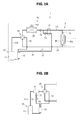
Fig. 1 is a front view partially illustrating a rotary compressor according to an embodiment of the present invention in cross section; -
Fig. 2A is a schematic view illustrating one example of a refrigeration cycle including the rotary compressor, andFig. 2B is a schematic view illustrating a pipe portion of an injection pipe in another example of the refrigeration cycle; -
Fig. 3 is a schematic view illustrating an internal structure of an accumulator provided in the rotary compressor; -
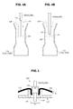
Fig. 4A is a schematic cross-sectional view illustrating a first example of a configuration that exhibits an ejector effect and is a main part of the present invention, andFig. 4B is a schematic cross-sectional view illustrating a second example thereof; and -
Fig. 5 is a schematic cross-sectional view illustrating a sealing portion of the injection pipe in the accumulator. - In the following detailed description, for purpose of explanation, numerous specific details are set forth in order to provide a thorough understanding of the disclosed embodiments. It will be apparent, however, that one or more embodiments may be practiced without these specific details. In other instances, well-known structures and devices are schematically shown in order to simplify the drawing.
- An object of the present invention is to improve a heating capacity by increasing a flow rate of a refrigerant that is suctioned into a compressor during a heating operation at a low ambient air temperature while adopting a method for supplying an injection refrigerant to the compressor via a refrigerant intake pipe.
- To achieve the above-described object, a rotary compressor according to an aspect of the present invention includes: a compressor body including an airtight container that has a refrigerant intake opening and a refrigerant discharge opening, a refrigerant compression unit that has a cylinder and a rotary piston housed in the cylinder and that is provided in the airtight container, and an electric motor that drives the rotary piston and is provided in the airtight container; and an accumulator configured to separate a refrigerant suctioned into the refrigerant intake opening into gas and liquid. The accumulator and the refrigerant intake opening are connected via a refrigerant intake pipe, a suction opening of the refrigerant intake pipe is arranged to be opened to the inside of the accumulator, an injection pipe for pouring the refrigerant into the rotary compressor is inserted into the accumulator from above, and a discharge opening of the injection pipe is drawn to face the suction opening of the refrigerant intake pipe in a refrigerant gas space of the accumulator.
- According to the aspect of the present invention, in order to avoid or suppress the entry of foreign substances into a gas-liquid separation chamber, it is preferred that a filter and a gas-liquid separation plate are arranged in the accumulator such that the filter is positioned on an upper side, and the injection pipe penetrates the filter and the gas-liquid separation plate and extends to the inside of the refrigerant gas space, and a penetrated portion is sealed by sealing means.
- The sealing means preferably includes a first sealing member that is formed in an annular shape toward the filter around a through hole of the gas-liquid separation plate, a cylindrical second sealing member that is fitted to an inside of the first sealing member with a clearance narrower than a thickness of the filter and that is fixed to a side of the injection pipe, and a peripheral edge portion of a through hole of the filter that is interposed between the first sealing member and the second sealing member. The second sealing member may be pressed into the first sealing member along with the peripheral edge portion of the through hole of the filter.
- According to a preferred aspect of the present invention, the injection pipe includes a first throttle portion with a reduced diameter at a pipe end on the discharge opening side. In addition, the refrigerant intake pipe includes a second throttle portion with a reduced diameter in a portion adjacent to the suction opening. Furthermore, the injection pipe preferably enters the inside of the second throttle portion of the refrigerant intake pipe.
- According to the present invention, the injection pipe is drawn from an upper portion of the accumulator and faces the suction opening of the refrigerant intake pipe in the refrigerant gas space. Preferably, a throttle portion is formed in the injection pipe and/or the refrigerant intake pipe. Accordingly, static pressure around the throttle portion is lowered by high-speed injection of a refrigerant flow from the injection pipe. Thus, the flow rate of the refrigerant supplied to the compressor is increased by an ejector effect that a gaseous refrigerant in the accumulator is suctioned into the refrigerant intake pipe, and the heating capacity is improved by the increase.
- Next, an embodiment of the present invention will be described with reference to
Figs. 1 to 6 . However, the present invention is not limited thereto. - Referring to
Fig. 1 , arotary compressor 10 according to this embodiment includes acompressor body 11 and anaccumulator 12 attached to thecompressor body 11 as a basic configuration. Therotary compressor 10 is incorporated in a refrigerant circuit RC illustrated inFigs. 2A and B . - The
compressor body 11 includes anairtight container 110. Theairtight container 110 has acylindrical container body 111, and anupper lid 112a and alower lid 112b that cover thecontainer body 111. Arefrigerant compression unit 115 and anelectric motor 113 are housed in theairtight container 110. - In this embodiment, the
refrigerant compression unit 115 includes a firstrefrigerant compression unit 115a and a secondrefrigerant compression unit 115b that are two refrigerant compression units vertically arranged in two stages. Each of the firstrefrigerant compression unit 115a and the secondrefrigerant compression unit 115b includes acylinder 116 and arotary piston 117 as a rotor that is housed in thecylinder 116. - The
rotary piston 117 on the firstrefrigerant compression unit 115a side and therotary piston 117 on the secondrefrigerant compression unit 115b side are eccentrically fixed to arotary drive shaft 113a of theelectric motor 113 and rotatably driven with a phase of 180°. - A refrigerant is suctioned into the first
refrigerant compression unit 115a and the secondrefrigerant compression unit 115b fromrefrigerant intake openings container body 111. A compressed refrigerant generated by the firstrefrigerant compression unit 115a is discharged into theairtight container 110 via anupper muffler 118a. In addition, a compressed refrigerant generated by the secondrefrigerant compression unit 115b is discharged into theairtight container 110 via alower muffler 118b. Each compressed refrigerant is supplied to the refrigerant circuit RC from arefrigerant discharge pipe 114 that is provided in theupper lid 112a. - It should be noted that, in the case where there is no need to distinguish the first
refrigerant compression unit 115a from the secondrefrigerant compression unit 115b, these are collectively referred to as therefrigerant compression unit 115. Similarly, in the case where there is no need to distinguish therefrigerant intake openings 119a from therefrigerant intake openings 119b, these are collectively referred to as arefrigerant intake opening 119. - The
accumulator 12 includes anairtight container 120. Similar to the above-describedairtight container 110, theairtight container 120 includes acylindrical container body 121, and anupper lid 122a and alower lid 122b that cover thecontainer body 121. Thisairtight container 120 is arranged with an axis thereof being substantially perpendicular, that is, placed vertically, and is attached to a side of thecompressor body 11 via fastening and fixing means such as a band, for example. - A
refrigerant return pipe 1C of the refrigerant circuit RC, which will be described below, and an injection pipe 50 (50a, 50b) are drawn into theaccumulator 12 from theupper lid 122a. In addition, a refrigerant intake pipe 124 (124a, 124b) that is connected to eachcylinder 116 in the refrigerant compression unit 115 (115a, 115b) is drawn from thelower lid 112b. - It should be noted that, in this embodiment, two
refrigerant compression units refrigerant compression unit 115, and each of them is actuated independently. Accordingly, the tworefrigerant intake pipes refrigerant compression units refrigerant compression unit 115 is provided, onerefrigerant intake pipe 124 to be drawn is provided. In the case where there is no need to distinguish the tworefrigerant intake pipes refrigerant intake pipe 124. - Here, the refrigerant circuit RC will be described with reference to
Fig. 2A . This refrigerant circuit RC is a circuit for an air conditioner of heat pump type that includes anoutdoor unit 1 and anindoor unit 2. In this refrigerant circuit RC, theoutdoor unit 1 and theindoor unit 2 are connected by a liquid-side refrigerant pipe 1A and a gas-siderefrigerant pipe 1B. - In an example illustrated in
Fig. 2 , oneindoor unit 2 is provided. Alternatively, pluralindoor units 2 may be connected in parallel between the liquid-side refrigerant pipe 1A and the gas-siderefrigerant pipe 1B. - The
outdoor unit 1 is provided with therotary compressor 10 having the above configuration, a four-way valve 20, anoutdoor heat exchanger 30, anoutdoor blowing fan 30a, anoutdoor expansion valve 31, and theinjection pipe 50. Theindoor unit 2 is provided with anindoor heat exchanger 40, anindoor blowing fan 40a, and anindoor expansion valve 41. - During a heating operation, as a basic operation, the four-
way valve 20 is switched as illustrated by chain lines inFig. 2A . Theoutdoor expansion valve 31 and theindoor expansion valve 41 are adjusted at specified opening degrees by a controller, which is not illustrated. - A gaseous refrigerant at a high temperature and high pressure that is generated in the
compressor body 11 and discharged from therefrigerant discharge pipe 114 is delivered to theindoor heat exchanger 40 via the four-way valve 20 and the gas-siderefrigerant pipe 1B. This gaseous refrigerant at the high temperature and the high pressure is cooled through heat exchange with indoor air, and is decompressed at theindoor expansion valve 41. Then, the refrigerant is returned to theoutdoor unit 1 side via the liquid-side refrigerant pipe 1A, and is decompressed at theoutdoor expansion valve 31. In this way, the refrigerant turns into a gas-liquid two-phase refrigerant at low pressure. This gas-liquid two-phase refrigerant is heated and evaporated through heat exchange with outdoor air in theoutdoor heat exchanger 30 and turns into a low-pressure refrigerant. This low-pressure refrigerant enters theaccumulator 12 from therefrigerant return pipe 1C through the four-way valve 20 and undergoes gas-liquid separation. The gaseous refrigerant after the gas-liquid separation is supplied to therefrigerant compression unit 115 via therefrigerant intake pipe 124. As described above, during the heating operation, theindoor heat exchanger 40 acts as a condenser, and theoutdoor heat exchanger 30 acts as an evaporator. - During a cooling operation, as a basic operation, the four-
way valve 20 is switched as illustrated by solid lines inFig. 2A . Theoutdoor expansion valve 31 is fully opened, and theindoor expansion valve 41 is adjusted at a specified opening degree by the controller, which is not illustrated. - The gaseous refrigerant at a high temperature and high pressure that is generated in the
compressor body 11 and discharged from therefrigerant discharge pipe 114 is delivered to theoutdoor heat exchanger 30 via the four-way valve 20. This gaseous refrigerant at the high temperature and the high pressure is cooled through heat exchange with outdoor air and turns into a liquefied refrigerant at high pressure. This liquefied refrigerant reaches theindoor unit 2 via the liquid-side refrigerant pipe 1A, and is decompressed at theindoor expansion valve 41. In this way, the refrigerant turns into a gas-liquid two-phase refrigerant. This gas-liquid two-phase refrigerant is evaporated through heat exchange with indoor air in theindoor heat exchanger 40 and turns into a gaseous refrigerant at low pressure. This gaseous refrigerant is returned to theoutdoor unit 1 side via the gas-siderefrigerant pipe 1B, enters theaccumulator 12 from therefrigerant return pipe 1C through the four-way valve 20, and undergoes gas-liquid separation. The gaseous refrigerant after the gas-liquid separation is supplied to therefrigerant compression unit 115 via therefrigerant intake pipe 124. As described above, during the cooling operation, theindoor heat exchanger 40 acts as an evaporator, and theoutdoor heat exchanger 30 acts as a condenser. - In the refrigerant circuit RC of
Fig. 2A , theinjection pipe 50 is branched from the liquid-side refrigerant pipe 1A at a position of the liquid-side refrigerant pipe 1A that is on an upstream side of theoutdoor expansion valve 31 during the heating operation and on a downstream side theoutdoor expansion valve 31 during the cooling operation. Theinjection pipe 50 runs through a double-pipe heat exchanger 32 for injection in which heat exchange between the refrigerant in theinjection pipe 50 and the refrigerant in the liquid-side refrigerant pipe 1A is carried out, and reaches theaccumulator 12. Theinjection pipe 50 is provided with a solenoid valve 53 for injection, an opening degree of which can be adjusted, and a switchingvalve 52 for an injection refrigerant. - As illustrated in
Fig. 2B , theinjection pipe 50 may be drawn from a gas-liquid separator 21 that is provided in therefrigerant discharge pipe 114 arranged between thecompressor body 11 and the four-way valve 20. - Referring to
Fig. 3 , theaccumulator 12 is provided with afilter 126 and a gas-liquid separation plate 127. Thefilter 126 is formed of a wire net or the like, for example, and removes foreign substances contained in the refrigerant. In regard to a positional relationship of them, thefilter 126 is arranged on an upper side, and the gas-liquid separation plate 127 is arranged on a lower side thereof. - The refrigerant supplied from the
refrigerant return pipe 1C undergoes the gas-liquid separation in the gas-liquid separation plate 127. A liquid refrigerant is reserved in a state of containing refrigerator oil in a lower section of theaccumulator 12. The gaseous refrigerant is reserved in an upper section thereof. A portion in which the liquid refrigerant is reserved is referred to as a liquidrefrigerant reservoir 120b, and a portion in which the gaseous refrigerant is reserved is referred to as arefrigerant gas space 120a as a matter of convenience. - In the
accumulator 12, therefrigerant intake pipes lower lid 122b, are erected substantially perpendicularly, and extend to therefrigerant gas space 120a. In therefrigerant gas space 120a,respective suction openings refrigerant intake pipes refrigerant intake pipes refrigerant reservoir 120b. It should be noted that, in the case where there is no need to distinguish thesuction openings suction opening 129. - According to the present invention, the
injection pipes upper lid 122a in theaccumulator 12 such that theinjection pipes filter 126 and the gas-liquid separation plate 127 and thatdischarge openings injection pipes suction openings refrigerant intake pipe 124 in therefrigerant gas space 120a. - In this embodiment, two
refrigerant intake pipes injection pipe 50 is branched into two at a specified position, which is not illustrated, and has theinjection pipes injection pipes accumulator 12. It should be noted that, in the case where there is no need to distinguish theinjection pipes injection pipe 50. Similarly, in the case where there is no need to distinguish thedischarge openings discharge opening 51. - During the heating operation, the pressure of the refrigerant that has undergone the heat exchange with indoor air in the
indoor heat exchanger 40 is lowered to a specified pressure at theindoor expansion valve 41. Then, the refrigerant is returned to theoutdoor unit 1 side via the liquid-side refrigerant pipe 1A. By turning on (i.e., opening) the switchingvalve 52, some of the refrigerant in the liquid-side refrigerant pipe 1A flows through theinjection pipe 50, is decompressed at the solenoid valve 53 for injection, and passes through the double-pipe heat exchanger 32 for injection. In this way, the heat exchange between the refrigerant in theinjection pipe 50 and the refrigerant in the liquid-side refrigerant pipe 1A is carried out. Thereafter, the refrigerant in theinjection pipe 50 is injected at high speed from the discharge opening 51 of theinjection pipe 50 into theaccumulator 12. - The injection refrigerant is injected at high speed from the discharge opening 51 of the
injection pipe 50 toward thesuction opening 129 of therefrigerant intake pipe 124, as described above. Accordingly, static pressure around the suction opening of therefrigerant intake pipe 124 is lowered. As a result, the gaseous refrigerant in theaccumulator 12 is drawn into therefrigerant intake pipe 124. - Due to this ejector effect, a flow rate of the refrigerant suctioned into the
refrigerant compression unit 115 is increased. Thus, in particular, a heating capacity during the heating operation at the low ambient air temperature can be ensured. While the injection refrigerant may be a gaseous refrigerant, it is preferably a liquid refrigerant. Since the inside of the compression chamber is cooled by injection of the liquid refrigerant, an increase in a discharge temperature can be suppressed. - In regard to arrangement of the discharge opening 51 of the
injection pipe 50 and thesuction opening 129 of therefrigerant intake pipe 124, as illustrated inFig. 4A , thedischarge opening 51 and thesuction opening 129 may face each other with an appropriate distance under a condition that the ejector effect can be obtained. Alternatively, as illustrated inFig. 4B , a pipe end on thedischarge opening 51 side of theinjection pipe 50 may be inserted into therefrigerant intake pipe 124. - In either case, in order to enhance the ejector effect, it is preferred to form a throttle portion (a first throttle portion) 141 with a reduced diameter at the pipe end on the
discharge opening 51 side of theinjection pipe 50 so as to form the pipe end on thedischarge opening 51 side in a nozzle shape. - In addition, a throttle portion (a second throttle portion) 142 with a reduced diameter may be provided in a part of the
refrigerant intake pipe 124. A flow velocity of the refrigerant is increased in thethrottle portion 142, and thus, the static pressure around the suction opening of therefrigerant intake pipe 124 can be further lowered. - It should be noted that, after the refrigerant passes through the
throttle portion 142, the flow velocity of the refrigerant is lowered due to an increase in a cross-sectional area of a refrigerant passage. Accordingly, the pressure of the refrigerant is increased. This results in an increase in suction pressure of therefrigerant compression unit 115, which also leads to a reduction in compression power of theelectric motor 113. - As described above, the
injection pipe 50 penetrates thefilter 126 and the gas-liquid separation plate 127 and is drawn into therefrigerant gas space 120a. If a clearance is generated in this penetrated portion, foreign substances may enter the reservoir of theaccumulator 12. - In view of the above, in this embodiment, the generation of the clearance in the penetrated portion is avoided or suppressed by sealing
means 130 as illustrated inFig. 5 . - This sealing means 130 includes a
first sealing member 131, a cylindricalsecond sealing member 132, and aperipheral edge portion 133 of a through hole of thefilter 126. Thefirst sealing member 131 is formed in an annular shape toward thefilter 126 side around a through hole of the gas-liquid separation plate 127. Thesecond sealing member 132 is fixed to theinjection pipe 50 side. Theperipheral edge portion 133 of the through hole of thefilter 126 is interposed between thefirst sealing member 131 and thesecond sealing member 132. - The
first sealing member 131 may be a cylindrical body that is brazed to the gas-liquid separation plate 127 and formed of a copper material, for example. However, in terms of easiness of processing, thefirst sealing member 131 is preferably an annular raised piece that is integrally formed with the gas-liquid separation plate 127 by burring. - The
second sealing member 132 may be a cylindrical body that is brazed to theinjection pipe 50 and formed of the copper material, for example. When an inner diameter of thefirst sealing member 131 is denoted by ϕ1, an outer diameter of thesecond sealing member 132 is denoted by ϕ2, and a thickness of the filter is denoted by T, the inner diameter ϕ1 of thefirst sealing member 131 and the outer diameter ϕ2 of thesecond sealing member 132 are defined as (ϕ1 - ϕ2) < T. - According to this sealing means 130, the
second sealing member 132 is pressed into thefirst sealing member 131 such that theperipheral edge portion 133 of the through hole of thefilter 126 is interposed between thefirst sealing member 131 and thesecond sealing member 132. Thus, the clearance in the penetrated portion of theinjection pipe 50 can be sealed. - The foregoing detailed description has been presented for the purposes of illustration and description. Many modifications and variations are possible in light of the above teaching. It is not intended to be exhaustive or to limit the subject matter described herein to the precise form disclosed. Although the subject matter has been described in language specific to structural features and/or methodological acts, it is to be understood that the subject matter defined in the appended claims is not necessarily limited to the specific features or acts described above. Rather, the specific features and acts described above are disclosed as example forms of implementing the claims appended hereto.
Claims (6)
- A rotary compressor (10) comprising:a compressor body (11) including an airtight container (111) that has a refrigerant intake opening (119) and a refrigerant discharge opening, a refrigerant compression unit (115) that has a cylinder (116) and a rotary piston (117) housed in the cylinder (116) and that is provided in the airtight container (111), and an electric motor (113) that drives the rotary piston (117) and is provided in the airtight container (111); andan accumulator (12) configured to separate a refrigerant suctioned into the refrigerant intake opening (119) into gas and liquid, whereinthe accumulator (12) and the refrigerant intake opening (119) are connected via a refrigerant intake pipe (124),a suction opening (129) of the refrigerant intake pipe (124) is arranged to be opened to an inside of the accumulator (12),an injection pipe (50) for pouring the refrigerant into the rotary compressor is inserted into the accumulator (12) from above, anda discharge opening (51) of the injection pipe (50) is drawn to face the suction opening (129) of the refrigerant intake pipe (124) in a refrigerant gas space (120a) of the accumulator (12).
- The rotary compressor according to claim 1, wherein
the discharge opening (51) of the injection pipe (50) enters an inside of a suction opening (129a, 129b) of the refrigerant intake pipe (124a, 124b). - The rotary compressor according to claim 1 or 2, wherein
a filter (126) and a gas-liquid separation plate (127) are arranged in the accumulator (12) such that the filter (126) is positioned on an upper side, and
the injection pipe (50) penetrates the filter (126) and the gas-liquid separation plate (127) and extends to an inside of the refrigerant gas space (120a), and a penetrated portion is sealed by sealing means (130). - The rotary compressor according to claim 3, wherein
the sealing means (130) includes a first sealing member (131) that is formed in an annular shape toward the filter (126) around a through hole of the gas-liquid separation plate (127), a cylindrical second sealing member (132) that is fitted to an inside of the first sealing member (131) with a clearance narrower than a thickness of the filter (126) and that is fixed to a side of the injection pipe, and a peripheral edge portion (133) of a through hole of the filter (126) that is interposed between the first sealing member (131) and the second sealing member (132), and
the second sealing member (132) is pressed into the first sealing member (131) along with the peripheral edge portion (133) of the through hole of the filter (126). - The rotary compressor according to any one of claims 1 to 4, wherein
the injection pipe (50) includes a first throttle portion (141) with a reduced diameter at a pipe end on a side of the discharge opening (51). - The rotary compressor according to any one of claims 1 to 5, wherein
the refrigerant intake pipe (124a, 124b) includes a second throttle portion (142) with a reduced diameter in a portion adjacent to the suction opening (120a, 129b).
Applications Claiming Priority (1)
| Application Number | Priority Date | Filing Date | Title |
|---|---|---|---|
| JP2014067535A JP6164427B2 (en) | 2014-03-28 | 2014-03-28 | Rotary compressor |
Publications (2)
| Publication Number | Publication Date |
|---|---|
| EP2924295A1 true EP2924295A1 (en) | 2015-09-30 |
| EP2924295B1 EP2924295B1 (en) | 2018-05-02 |
Family
ID=52784970
Family Applications (1)
| Application Number | Title | Priority Date | Filing Date |
|---|---|---|---|
| EP15161483.1A Not-in-force EP2924295B1 (en) | 2014-03-28 | 2015-03-27 | Refrigeration circuit |
Country Status (5)
| Country | Link |
|---|---|
| US (1) | US9664191B2 (en) |
| EP (1) | EP2924295B1 (en) |
| JP (1) | JP6164427B2 (en) |
| CN (1) | CN104948461B (en) |
| AU (1) | AU2015201553B2 (en) |
Families Citing this family (9)
| Publication number | Priority date | Publication date | Assignee | Title |
|---|---|---|---|---|
| US9976785B2 (en) * | 2014-05-15 | 2018-05-22 | Lennox Industries Inc. | Liquid line charge compensator |
| US10330358B2 (en) | 2014-05-15 | 2019-06-25 | Lennox Industries Inc. | System for refrigerant pressure relief in HVAC systems |
| CN106461275B (en) * | 2014-07-23 | 2019-04-26 | 三菱电机株式会社 | Refrigerating circulatory device |
| CN105674435B (en) * | 2016-01-25 | 2018-11-02 | 珠海格力电器股份有限公司 | A kind of method for perfusing refrigerant of air-conditioner outdoor unit |
| US10989196B2 (en) * | 2016-07-14 | 2021-04-27 | Daikin Industries, Ltd. | Compressor having muffler function |
| JP6704526B2 (en) * | 2017-07-25 | 2020-06-03 | 三菱電機株式会社 | Refrigeration cycle equipment |
| WO2019142408A1 (en) | 2018-01-18 | 2019-07-25 | 東芝キヤリア株式会社 | Compressor and refrigeration cycle device |
| US10663199B2 (en) | 2018-04-19 | 2020-05-26 | Lennox Industries Inc. | Method and apparatus for common manifold charge compensator |
| US10830514B2 (en) | 2018-06-21 | 2020-11-10 | Lennox Industries Inc. | Method and apparatus for charge compensator reheat valve |
Citations (4)
| Publication number | Priority date | Publication date | Assignee | Title |
|---|---|---|---|---|
| EP0935106A2 (en) * | 1998-02-06 | 1999-08-11 | SANYO ELECTRIC Co., Ltd. | Multi-stage compressing refrigeration device and refrigerator using the device |
| WO2003060324A1 (en) * | 2001-12-28 | 2003-07-24 | Lg Electronics Inc. | Compressor having vibration reducing structure |
| EP2042740A2 (en) * | 2007-09-25 | 2009-04-01 | Fujitsu General Limited | two-stage rotary compressor |
| JP2013245837A (en) | 2012-05-23 | 2013-12-09 | Daikin Industries Ltd | Refrigerating system |
Family Cites Families (15)
| Publication number | Priority date | Publication date | Assignee | Title |
|---|---|---|---|---|
| US3167930A (en) * | 1962-11-19 | 1965-02-02 | Freightliner Corp | Refrigeration system |
| US4215555A (en) * | 1978-10-02 | 1980-08-05 | Carrier Corporation | Hot gas defrost system |
| JPS57129286A (en) * | 1981-02-02 | 1982-08-11 | Hitachi Ltd | Rotary compressor |
| JPS58148290A (en) * | 1982-02-26 | 1983-09-03 | Hitachi Ltd | Refrigerator with acroll compressor |
| JPS5925065U (en) * | 1982-08-07 | 1984-02-16 | 松下冷機株式会社 | Heat pump air conditioner |
| JPH065567Y2 (en) * | 1986-05-09 | 1994-02-09 | 三洋電機株式会社 | Refrigeration equipment |
| US6569347B1 (en) * | 1995-12-28 | 2003-05-27 | Daikin Industries, Ltd. | Refrigerating machine oil and refrigerator using the same |
| JPH1137578A (en) * | 1997-07-16 | 1999-02-12 | Toshiba Corp | Air conditioner |
| JP2000337261A (en) * | 1999-05-26 | 2000-12-05 | Funai Electric Co Ltd | Compressor |
| JP2001330343A (en) * | 2000-05-19 | 2001-11-30 | Fujitsu General Ltd | Accumulator for compressor |
| KR100531902B1 (en) * | 2003-06-12 | 2005-11-29 | 엘지전자 주식회사 | Accumulator for rotary compressor |
| CN1862021A (en) * | 2005-05-09 | 2006-11-15 | 乐金电子(天津)电器有限公司 | Structure of gas-liquid separator with rotary dual cylinder compressor |
| CN2856497Y (en) * | 2005-07-12 | 2007-01-10 | 乐金电子(天津)电器有限公司 | Connection structure of storage pot of compressor |
| KR100747496B1 (en) * | 2006-11-27 | 2007-08-08 | 삼성전자주식회사 | Rotary compressor and control method thereof and air conditioner using the same |
| JP2013096602A (en) * | 2011-10-28 | 2013-05-20 | Panasonic Corp | Refrigeration cycle device |
-
2014
- 2014-03-28 JP JP2014067535A patent/JP6164427B2/en active Active
-
2015
- 2015-03-25 AU AU2015201553A patent/AU2015201553B2/en not_active Ceased
- 2015-03-26 US US14/669,774 patent/US9664191B2/en active Active
- 2015-03-27 CN CN201510142436.9A patent/CN104948461B/en not_active Expired - Fee Related
- 2015-03-27 EP EP15161483.1A patent/EP2924295B1/en not_active Not-in-force
Patent Citations (4)
| Publication number | Priority date | Publication date | Assignee | Title |
|---|---|---|---|---|
| EP0935106A2 (en) * | 1998-02-06 | 1999-08-11 | SANYO ELECTRIC Co., Ltd. | Multi-stage compressing refrigeration device and refrigerator using the device |
| WO2003060324A1 (en) * | 2001-12-28 | 2003-07-24 | Lg Electronics Inc. | Compressor having vibration reducing structure |
| EP2042740A2 (en) * | 2007-09-25 | 2009-04-01 | Fujitsu General Limited | two-stage rotary compressor |
| JP2013245837A (en) | 2012-05-23 | 2013-12-09 | Daikin Industries Ltd | Refrigerating system |
Also Published As
| Publication number | Publication date |
|---|---|
| JP6164427B2 (en) | 2017-07-19 |
| CN104948461A (en) | 2015-09-30 |
| US20150275895A1 (en) | 2015-10-01 |
| AU2015201553B2 (en) | 2018-11-08 |
| US9664191B2 (en) | 2017-05-30 |
| CN104948461B (en) | 2018-12-11 |
| EP2924295B1 (en) | 2018-05-02 |
| AU2015201553A1 (en) | 2015-10-15 |
| JP2015190668A (en) | 2015-11-02 |
Similar Documents
| Publication | Publication Date | Title |
|---|---|---|
| EP2924295B1 (en) | Refrigeration circuit | |
| CN203717344U (en) | Rotary compressor and refrigeration cycle system provided with same | |
| TWI656310B (en) | High pressure compressor and refrigerating machine having the same | |
| KR101208141B1 (en) | Scroll compressor | |
| JP2006070892A (en) | Intake muffler for compressor | |
| CN100443725C (en) | Compression system, multicylinder rotary compressor, and refrigeration apparatus using the same | |
| WO2014083901A1 (en) | Compressor, refrigeration cycle device, and heat pump hot-water supply device | |
| KR20120007337A (en) | Compressor | |
| KR101212642B1 (en) | Mechanism for controlling and operating compressor capacity and air conditioner having the same | |
| CN105604940A (en) | Multi-cylinder rotating compressor and refrigeration system with same | |
| KR101275921B1 (en) | Hermetic type compressor | |
| CN203980699U (en) | Air-conditioning system | |
| CN104806524B (en) | Rotary compression thermomechanical components | |
| CN204738964U (en) | Rotary compressor subassembly and air conditioning system | |
| CN203980702U (en) | Air-conditioning system | |
| CN205533232U (en) | Multi -cylinder rotary compressor and have its refrigerating system | |
| KR100504923B1 (en) | Fluid mixing apparatus in accumulator for heat pump | |
| JP2010196630A (en) | Compressor | |
| JP5892261B2 (en) | Refrigeration cycle apparatus and heat pump water heater | |
| EP3492748A1 (en) | Compressor as well as cooling-heating refrigeration device and cooling-only refrigeration device having same | |
| JPH11337197A (en) | Refrigeration cycle | |
| JP2014029158A (en) | Refrigeration device | |
| JPH0122555B2 (en) |
Legal Events
| Date | Code | Title | Description |
|---|---|---|---|
| PUAI | Public reference made under article 153(3) epc to a published international application that has entered the european phase |
Free format text: ORIGINAL CODE: 0009012 |
|
| AK | Designated contracting states |
Kind code of ref document: A1 Designated state(s): AL AT BE BG CH CY CZ DE DK EE ES FI FR GB GR HR HU IE IS IT LI LT LU LV MC MK MT NL NO PL PT RO RS SE SI SK SM TR |
|
| AX | Request for extension of the european patent |
Extension state: BA ME |
|
| 17P | Request for examination filed |
Effective date: 20160329 |
|
| RBV | Designated contracting states (corrected) |
Designated state(s): AL AT BE BG CH CY CZ DE DK EE ES FI FR GB GR HR HU IE IS IT LI LT LU LV MC MK MT NL NO PL PT RO RS SE SI SK SM TR |
|
| STAA | Information on the status of an ep patent application or granted ep patent |
Free format text: STATUS: EXAMINATION IS IN PROGRESS |
|
| 17Q | First examination report despatched |
Effective date: 20170418 |
|
| GRAP | Despatch of communication of intention to grant a patent |
Free format text: ORIGINAL CODE: EPIDOSNIGR1 |
|
| STAA | Information on the status of an ep patent application or granted ep patent |
Free format text: STATUS: GRANT OF PATENT IS INTENDED |
|
| RAP1 | Party data changed (applicant data changed or rights of an application transferred) |
Owner name: FUJITSU GENERAL LIMITED |
|
| INTG | Intention to grant announced |
Effective date: 20171010 |
|
| GRAS | Grant fee paid |
Free format text: ORIGINAL CODE: EPIDOSNIGR3 |
|
| GRAJ | Information related to disapproval of communication of intention to grant by the applicant or resumption of examination proceedings by the epo deleted |
Free format text: ORIGINAL CODE: EPIDOSDIGR1 |
|
| GRAL | Information related to payment of fee for publishing/printing deleted |
Free format text: ORIGINAL CODE: EPIDOSDIGR3 |
|
| STAA | Information on the status of an ep patent application or granted ep patent |
Free format text: STATUS: EXAMINATION IS IN PROGRESS |
|
| GRAR | Information related to intention to grant a patent recorded |
Free format text: ORIGINAL CODE: EPIDOSNIGR71 |
|
| STAA | Information on the status of an ep patent application or granted ep patent |
Free format text: STATUS: GRANT OF PATENT IS INTENDED |
|
| INTC | Intention to grant announced (deleted) | ||
| GRAA | (expected) grant |
Free format text: ORIGINAL CODE: 0009210 |
|
| STAA | Information on the status of an ep patent application or granted ep patent |
Free format text: STATUS: THE PATENT HAS BEEN GRANTED |
|
| INTG | Intention to grant announced |
Effective date: 20180321 |
|
| AK | Designated contracting states |
Kind code of ref document: B1 Designated state(s): AL AT BE BG CH CY CZ DE DK EE ES FI FR GB GR HR HU IE IS IT LI LT LU LV MC MK MT NL NO PL PT RO RS SE SI SK SM TR |
|
| REG | Reference to a national code |
Ref country code: GB Ref legal event code: FG4D |
|
| REG | Reference to a national code |
Ref country code: CH Ref legal event code: EP Ref country code: AT Ref legal event code: REF Ref document number: 995560 Country of ref document: AT Kind code of ref document: T Effective date: 20180515 |
|
| REG | Reference to a national code |
Ref country code: DE Ref legal event code: R096 Ref document number: 602015010582 Country of ref document: DE Ref country code: IE Ref legal event code: FG4D |
|
| REG | Reference to a national code |
Ref country code: NL Ref legal event code: MP Effective date: 20180502 |
|
| REG | Reference to a national code |
Ref country code: LT Ref legal event code: MG4D |
|
| PG25 | Lapsed in a contracting state [announced via postgrant information from national office to epo] |
Ref country code: SE Free format text: LAPSE BECAUSE OF FAILURE TO SUBMIT A TRANSLATION OF THE DESCRIPTION OR TO PAY THE FEE WITHIN THE PRESCRIBED TIME-LIMIT Effective date: 20180502 Ref country code: BG Free format text: LAPSE BECAUSE OF FAILURE TO SUBMIT A TRANSLATION OF THE DESCRIPTION OR TO PAY THE FEE WITHIN THE PRESCRIBED TIME-LIMIT Effective date: 20180802 Ref country code: FI Free format text: LAPSE BECAUSE OF FAILURE TO SUBMIT A TRANSLATION OF THE DESCRIPTION OR TO PAY THE FEE WITHIN THE PRESCRIBED TIME-LIMIT Effective date: 20180502 Ref country code: LT Free format text: LAPSE BECAUSE OF FAILURE TO SUBMIT A TRANSLATION OF THE DESCRIPTION OR TO PAY THE FEE WITHIN THE PRESCRIBED TIME-LIMIT Effective date: 20180502 Ref country code: NO Free format text: LAPSE BECAUSE OF FAILURE TO SUBMIT A TRANSLATION OF THE DESCRIPTION OR TO PAY THE FEE WITHIN THE PRESCRIBED TIME-LIMIT Effective date: 20180802 Ref country code: ES Free format text: LAPSE BECAUSE OF FAILURE TO SUBMIT A TRANSLATION OF THE DESCRIPTION OR TO PAY THE FEE WITHIN THE PRESCRIBED TIME-LIMIT Effective date: 20180502 |
|
| PG25 | Lapsed in a contracting state [announced via postgrant information from national office to epo] |
Ref country code: HR Free format text: LAPSE BECAUSE OF FAILURE TO SUBMIT A TRANSLATION OF THE DESCRIPTION OR TO PAY THE FEE WITHIN THE PRESCRIBED TIME-LIMIT Effective date: 20180502 Ref country code: GR Free format text: LAPSE BECAUSE OF FAILURE TO SUBMIT A TRANSLATION OF THE DESCRIPTION OR TO PAY THE FEE WITHIN THE PRESCRIBED TIME-LIMIT Effective date: 20180803 Ref country code: NL Free format text: LAPSE BECAUSE OF FAILURE TO SUBMIT A TRANSLATION OF THE DESCRIPTION OR TO PAY THE FEE WITHIN THE PRESCRIBED TIME-LIMIT Effective date: 20180502 Ref country code: LV Free format text: LAPSE BECAUSE OF FAILURE TO SUBMIT A TRANSLATION OF THE DESCRIPTION OR TO PAY THE FEE WITHIN THE PRESCRIBED TIME-LIMIT Effective date: 20180502 Ref country code: RS Free format text: LAPSE BECAUSE OF FAILURE TO SUBMIT A TRANSLATION OF THE DESCRIPTION OR TO PAY THE FEE WITHIN THE PRESCRIBED TIME-LIMIT Effective date: 20180502 |
|
| REG | Reference to a national code |
Ref country code: AT Ref legal event code: MK05 Ref document number: 995560 Country of ref document: AT Kind code of ref document: T Effective date: 20180502 |
|
| PG25 | Lapsed in a contracting state [announced via postgrant information from national office to epo] |
Ref country code: RO Free format text: LAPSE BECAUSE OF FAILURE TO SUBMIT A TRANSLATION OF THE DESCRIPTION OR TO PAY THE FEE WITHIN THE PRESCRIBED TIME-LIMIT Effective date: 20180502 Ref country code: SK Free format text: LAPSE BECAUSE OF FAILURE TO SUBMIT A TRANSLATION OF THE DESCRIPTION OR TO PAY THE FEE WITHIN THE PRESCRIBED TIME-LIMIT Effective date: 20180502 Ref country code: CZ Free format text: LAPSE BECAUSE OF FAILURE TO SUBMIT A TRANSLATION OF THE DESCRIPTION OR TO PAY THE FEE WITHIN THE PRESCRIBED TIME-LIMIT Effective date: 20180502 Ref country code: EE Free format text: LAPSE BECAUSE OF FAILURE TO SUBMIT A TRANSLATION OF THE DESCRIPTION OR TO PAY THE FEE WITHIN THE PRESCRIBED TIME-LIMIT Effective date: 20180502 Ref country code: AT Free format text: LAPSE BECAUSE OF FAILURE TO SUBMIT A TRANSLATION OF THE DESCRIPTION OR TO PAY THE FEE WITHIN THE PRESCRIBED TIME-LIMIT Effective date: 20180502 Ref country code: DK Free format text: LAPSE BECAUSE OF FAILURE TO SUBMIT A TRANSLATION OF THE DESCRIPTION OR TO PAY THE FEE WITHIN THE PRESCRIBED TIME-LIMIT Effective date: 20180502 Ref country code: PL Free format text: LAPSE BECAUSE OF FAILURE TO SUBMIT A TRANSLATION OF THE DESCRIPTION OR TO PAY THE FEE WITHIN THE PRESCRIBED TIME-LIMIT Effective date: 20180502 |
|
| REG | Reference to a national code |
Ref country code: DE Ref legal event code: R097 Ref document number: 602015010582 Country of ref document: DE |
|
| PG25 | Lapsed in a contracting state [announced via postgrant information from national office to epo] |
Ref country code: IT Free format text: LAPSE BECAUSE OF FAILURE TO SUBMIT A TRANSLATION OF THE DESCRIPTION OR TO PAY THE FEE WITHIN THE PRESCRIBED TIME-LIMIT Effective date: 20180502 Ref country code: SM Free format text: LAPSE BECAUSE OF FAILURE TO SUBMIT A TRANSLATION OF THE DESCRIPTION OR TO PAY THE FEE WITHIN THE PRESCRIBED TIME-LIMIT Effective date: 20180502 |
|
| PLBE | No opposition filed within time limit |
Free format text: ORIGINAL CODE: 0009261 |
|
| STAA | Information on the status of an ep patent application or granted ep patent |
Free format text: STATUS: NO OPPOSITION FILED WITHIN TIME LIMIT |
|
| 26N | No opposition filed |
Effective date: 20190205 |
|
| PG25 | Lapsed in a contracting state [announced via postgrant information from national office to epo] |
Ref country code: SI Free format text: LAPSE BECAUSE OF FAILURE TO SUBMIT A TRANSLATION OF THE DESCRIPTION OR TO PAY THE FEE WITHIN THE PRESCRIBED TIME-LIMIT Effective date: 20180502 |
|
| PG25 | Lapsed in a contracting state [announced via postgrant information from national office to epo] |
Ref country code: MC Free format text: LAPSE BECAUSE OF FAILURE TO SUBMIT A TRANSLATION OF THE DESCRIPTION OR TO PAY THE FEE WITHIN THE PRESCRIBED TIME-LIMIT Effective date: 20180502 |
|
| REG | Reference to a national code |
Ref country code: CH Ref legal event code: PL |
|
| PG25 | Lapsed in a contracting state [announced via postgrant information from national office to epo] |
Ref country code: LU Free format text: LAPSE BECAUSE OF NON-PAYMENT OF DUE FEES Effective date: 20190327 Ref country code: AL Free format text: LAPSE BECAUSE OF FAILURE TO SUBMIT A TRANSLATION OF THE DESCRIPTION OR TO PAY THE FEE WITHIN THE PRESCRIBED TIME-LIMIT Effective date: 20180502 |
|
| REG | Reference to a national code |
Ref country code: BE Ref legal event code: MM Effective date: 20190331 |
|
| PG25 | Lapsed in a contracting state [announced via postgrant information from national office to epo] |
Ref country code: LI Free format text: LAPSE BECAUSE OF NON-PAYMENT OF DUE FEES Effective date: 20190331 Ref country code: IE Free format text: LAPSE BECAUSE OF NON-PAYMENT OF DUE FEES Effective date: 20190327 Ref country code: CH Free format text: LAPSE BECAUSE OF NON-PAYMENT OF DUE FEES Effective date: 20190331 |
|
| PG25 | Lapsed in a contracting state [announced via postgrant information from national office to epo] |
Ref country code: BE Free format text: LAPSE BECAUSE OF NON-PAYMENT OF DUE FEES Effective date: 20190331 |
|
| PG25 | Lapsed in a contracting state [announced via postgrant information from national office to epo] |
Ref country code: TR Free format text: LAPSE BECAUSE OF FAILURE TO SUBMIT A TRANSLATION OF THE DESCRIPTION OR TO PAY THE FEE WITHIN THE PRESCRIBED TIME-LIMIT Effective date: 20180502 |
|
| PG25 | Lapsed in a contracting state [announced via postgrant information from national office to epo] |
Ref country code: MT Free format text: LAPSE BECAUSE OF NON-PAYMENT OF DUE FEES Effective date: 20190327 Ref country code: PT Free format text: LAPSE BECAUSE OF FAILURE TO SUBMIT A TRANSLATION OF THE DESCRIPTION OR TO PAY THE FEE WITHIN THE PRESCRIBED TIME-LIMIT Effective date: 20180903 |
|
| PG25 | Lapsed in a contracting state [announced via postgrant information from national office to epo] |
Ref country code: CY Free format text: LAPSE BECAUSE OF FAILURE TO SUBMIT A TRANSLATION OF THE DESCRIPTION OR TO PAY THE FEE WITHIN THE PRESCRIBED TIME-LIMIT Effective date: 20180502 |
|
| PG25 | Lapsed in a contracting state [announced via postgrant information from national office to epo] |
Ref country code: IS Free format text: LAPSE BECAUSE OF FAILURE TO SUBMIT A TRANSLATION OF THE DESCRIPTION OR TO PAY THE FEE WITHIN THE PRESCRIBED TIME-LIMIT Effective date: 20180902 |
|
| PG25 | Lapsed in a contracting state [announced via postgrant information from national office to epo] |
Ref country code: HU Free format text: LAPSE BECAUSE OF FAILURE TO SUBMIT A TRANSLATION OF THE DESCRIPTION OR TO PAY THE FEE WITHIN THE PRESCRIBED TIME-LIMIT; INVALID AB INITIO Effective date: 20150327 |
|
| PGFP | Annual fee paid to national office [announced via postgrant information from national office to epo] |
Ref country code: GB Payment date: 20220203 Year of fee payment: 8 Ref country code: DE Payment date: 20220203 Year of fee payment: 8 |
|
| PGFP | Annual fee paid to national office [announced via postgrant information from national office to epo] |
Ref country code: FR Payment date: 20220209 Year of fee payment: 8 |
|
| PG25 | Lapsed in a contracting state [announced via postgrant information from national office to epo] |
Ref country code: MK Free format text: LAPSE BECAUSE OF FAILURE TO SUBMIT A TRANSLATION OF THE DESCRIPTION OR TO PAY THE FEE WITHIN THE PRESCRIBED TIME-LIMIT Effective date: 20180502 |
|
| REG | Reference to a national code |
Ref country code: DE Ref legal event code: R119 Ref document number: 602015010582 Country of ref document: DE |
|
| GBPC | Gb: european patent ceased through non-payment of renewal fee |
Effective date: 20230327 |
|
| PG25 | Lapsed in a contracting state [announced via postgrant information from national office to epo] |
Ref country code: GB Free format text: LAPSE BECAUSE OF NON-PAYMENT OF DUE FEES Effective date: 20230327 |
|
| PG25 | Lapsed in a contracting state [announced via postgrant information from national office to epo] |
Ref country code: GB Free format text: LAPSE BECAUSE OF NON-PAYMENT OF DUE FEES Effective date: 20230327 Ref country code: FR Free format text: LAPSE BECAUSE OF NON-PAYMENT OF DUE FEES Effective date: 20230331 Ref country code: DE Free format text: LAPSE BECAUSE OF NON-PAYMENT OF DUE FEES Effective date: 20231003 |