EP2924263B1 - Zündkreissystem mit siliziumkarbid-entladeschalter - Google Patents
Zündkreissystem mit siliziumkarbid-entladeschalter Download PDFInfo
- Publication number
- EP2924263B1 EP2924263B1 EP15159494.2A EP15159494A EP2924263B1 EP 2924263 B1 EP2924263 B1 EP 2924263B1 EP 15159494 A EP15159494 A EP 15159494A EP 2924263 B1 EP2924263 B1 EP 2924263B1
- Authority
- EP
- European Patent Office
- Prior art keywords
- silicon carbide
- energy source
- discharge switch
- exciter system
- ignition exciter
- Prior art date
- Legal status (The legal status is an assumption and is not a legal conclusion. Google has not performed a legal analysis and makes no representation as to the accuracy of the status listed.)
- Active
Links
Images


Classifications
-
- F—MECHANICAL ENGINEERING; LIGHTING; HEATING; WEAPONS; BLASTING
- F02—COMBUSTION ENGINES; HOT-GAS OR COMBUSTION-PRODUCT ENGINE PLANTS
- F02C—GAS-TURBINE PLANTS; AIR INTAKES FOR JET-PROPULSION PLANTS; CONTROLLING FUEL SUPPLY IN AIR-BREATHING JET-PROPULSION PLANTS
- F02C7/00—Features, components parts, details or accessories, not provided for in, or of interest apart form groups F02C1/00 - F02C6/00; Air intakes for jet-propulsion plants
- F02C7/26—Starting; Ignition
- F02C7/264—Ignition
- F02C7/266—Electric
-
- F—MECHANICAL ENGINEERING; LIGHTING; HEATING; WEAPONS; BLASTING
- F02—COMBUSTION ENGINES; HOT-GAS OR COMBUSTION-PRODUCT ENGINE PLANTS
- F02P—IGNITION, OTHER THAN COMPRESSION IGNITION, FOR INTERNAL-COMBUSTION ENGINES; TESTING OF IGNITION TIMING IN COMPRESSION-IGNITION ENGINES
- F02P15/00—Electric spark ignition having characteristics not provided for in, or of interest apart from, groups F02P1/00 - F02P13/00 and combined with layout of ignition circuits
- F02P15/001—Ignition installations adapted to specific engine types
- F02P15/003—Layout of ignition circuits for gas turbine plants
-
- F—MECHANICAL ENGINEERING; LIGHTING; HEATING; WEAPONS; BLASTING
- F02—COMBUSTION ENGINES; HOT-GAS OR COMBUSTION-PRODUCT ENGINE PLANTS
- F02P—IGNITION, OTHER THAN COMPRESSION IGNITION, FOR INTERNAL-COMBUSTION ENGINES; TESTING OF IGNITION TIMING IN COMPRESSION-IGNITION ENGINES
- F02P3/00—Other installations
- F02P3/06—Other installations having capacitive energy storage
- F02P3/08—Layout of circuits
- F02P3/0876—Layout of circuits the storage capacitor being charged by means of an energy converter (DC-DC converter) or of an intermediate storage inductance
- F02P3/0884—Closing the discharge circuit of the storage capacitor with semiconductor devices
-
- H—ELECTRICITY
- H01—ELECTRIC ELEMENTS
- H01T—SPARK GAPS; OVERVOLTAGE ARRESTERS USING SPARK GAPS; SPARKING PLUGS; CORONA DEVICES; GENERATING IONS TO BE INTRODUCED INTO NON-ENCLOSED GASES
- H01T15/00—Circuits specially adapted for spark gaps, e.g. ignition circuits
-
- F—MECHANICAL ENGINEERING; LIGHTING; HEATING; WEAPONS; BLASTING
- F05—INDEXING SCHEMES RELATING TO ENGINES OR PUMPS IN VARIOUS SUBCLASSES OF CLASSES F01-F04
- F05D—INDEXING SCHEME FOR ASPECTS RELATING TO NON-POSITIVE-DISPLACEMENT MACHINES OR ENGINES, GAS-TURBINES OR JET-PROPULSION PLANTS
- F05D2220/00—Application
- F05D2220/30—Application in turbines
- F05D2220/32—Application in turbines in gas turbines
-
- F—MECHANICAL ENGINEERING; LIGHTING; HEATING; WEAPONS; BLASTING
- F05—INDEXING SCHEMES RELATING TO ENGINES OR PUMPS IN VARIOUS SUBCLASSES OF CLASSES F01-F04
- F05D—INDEXING SCHEME FOR ASPECTS RELATING TO NON-POSITIVE-DISPLACEMENT MACHINES OR ENGINES, GAS-TURBINES OR JET-PROPULSION PLANTS
- F05D2260/00—Function
- F05D2260/42—Storage of energy
-
- F—MECHANICAL ENGINEERING; LIGHTING; HEATING; WEAPONS; BLASTING
- F05—INDEXING SCHEMES RELATING TO ENGINES OR PUMPS IN VARIOUS SUBCLASSES OF CLASSES F01-F04
- F05D—INDEXING SCHEME FOR ASPECTS RELATING TO NON-POSITIVE-DISPLACEMENT MACHINES OR ENGINES, GAS-TURBINES OR JET-PROPULSION PLANTS
- F05D2260/00—Function
- F05D2260/99—Ignition, e.g. ignition by warming up of fuel or oxidizer in a resonant acoustic cavity
Definitions
- Gas turbine engines for aircraft typically include an ignition system to aid in the starting of the engine.
- the engine ignition system may include an ignition exciter that stores energy and releases a high-energy spark to produce combustion of fuel in the engine in a way that is analogous to automobile ignition coils.
- the ignition exciter may provide sparks during initial engine start on the ground or, depending upon the environmental conditions, while the aircraft is airborne to prevent combustion from failing.
- US 5,656,966 relates to a turbine engine ignition exciter circuit having low voltage lockout control.
- an embodiment of the invention relates an ignition exciter system for igniting fuel in a gas turbine engine.
- the ignition exciter system comprises a rechargeable energy source, at least one pulse-forming network coupled to the rechargeable energy source and generating a stored energy waveform from energy in the rechargeable energy source, at least one igniter plug coupled to the at least one pulse-forming network to receive the stored energy waveform and generating a spark in response to the received stored energy waveform, a silicon carbide discharge switch further comprising a gate, an anode and a cathode and a switch driver electrically coupled to the silicon carbide discharge switch to apply a positive electrical triggering waveform to the anode with respect to the gate of the silicon carbide discharge switch so as to inductively switch the silicon carbide discharge switch to transition from a non-conducting state to a conducting state when voltage in the rechargeable energy source reaches a predetermined level for energy storage.
- the anode and cathode of the silicon carbide discharge switch is connected in series with the rechargeable energy source selectively coupling the rechargeable energy source to the at least one pulse forming network in response to the positive electrical triggering waveform to effect the generating of the stored energy waveform, which is then received by the igniter plug to generate the spark.
- FIG. 1 is a schematic view of an exemplary gas turbine engine 10 that includes a core engine section 12 positioned axially downstream from a fan section 14 along a longitudinal axis 15.
- the core engine section 12 includes a generally tubular outer casing 16 that defines an annular core engine inlet 18 and that encloses and supports a pressure booster 20 for use in raising the pressure of the air that enters the core engine section 12 to a first pressure level.
- a high-pressure, multi-stage, axial-flow compressor 22 receives pressurized air from the booster 20 and further increases the pressure of the air.
- the pressurized air flows to a combustor 24 where fuel is injected into the pressurized air stream to raise the temperature and energy level of the pressurized air.
- One or more igniter plugs 25A and 25B coupled via lead lines 27A and 27B to an ignition exciter circuit 29 may facilitate the initiation of combustion of the fuel air mixture in the combustor 24.
- the ignition exciter circuit 29 is additionally coupled to a DC power source via a power source connector 31.
- the high energy combustion products flow to a first turbine 26 for use in driving the compressor 22 through a first drive shaft 28, and then to a second turbine 30 for use in driving the booster 20 through a second drive shaft 32 that is coaxial with the first drive shaft 28.
- the combustion products provide propulsive jet thrust by being channeled from the core engine section 12 through an exhaust nozzle 34.
- the fan section 14 Surrounded by an annular fan casing 38, the fan section 14 includes a rotatable, axial-flow fan rotor 36.
- the fan casing 38 is supported about the core engine section 12 by a plurality of substantially radially-extending, circumferentially-spaced support struts 40.
- the fan casing 38 is supported by radially extending outlet guide vanes 42 and encloses the fan rotor 36 and a plurality of fan rotor blades 44.
- a downstream section 39 of the fan casing 38 extends over an outer portion of the core engine 12 to define a secondary, or bypass, airflow conduit 46 that provides additional propulsive jet thrust.
- the engine ignition system described herein is equally applicable to industrial turbine-powered applications without loss of generality.
- gas turbine engines may drive a generator for generating electricity.
- gas turbine engines may power industrial machinery for a wide range of applications.
- the engine ignition system may be configured and implemented for a particular gas turbine engine and corresponding commercial or industrial application accordingly.
- a commercial aircraft engine may use a single igniter plug 25A coupled via lead lines 27A to the ignition exciter circuit 29 whereas a gas turbine engine connected to an electrical generator may use two igniter plugs 25A and 25B coupled via lead lines 27A and 27B to the ignition exciter circuit 29.
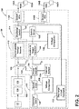
- FIG. 2 is a schematic block diagram of an engine ignition system 100 with an ignition exciter charging in accordance with an embodiment of the invention.
- the engine ignition system 100 includes an ignition exciter circuit 102, an ignition lead 104, and an igniter plug 106.
- the ignition exciter circuit 102 comprises an electronic unit that includes an EMI filter module 108, a power converter 110, a rechargeable energy source 112, a voltage monitoring circuit and discharge switch module 114, and one or more pulse-forming networks (PFN) 116A and B.
- the EMI filter module 108 is configured to receive a supply of relatively low, direct current (DC) voltage, for example, 28 volts DC from a DC source 117.
- DC direct current
- DC sources may include elements of an aircraft electrical power system including, but not limited to a battery, a DC bus line or an auxiliary power unit (APU).
- the source may deliver DC voltage ranging from 28 volts DC up to 270 volts DC.
- the source may provide alternating current (AC) such as 115 volts AC at a frequency of 400 Hertz (Hz).
- AC alternating current
- the EMI filter module 108 includes an EMI filter 118 and a smoothing capacitor 119 configured to prevent high frequency noise generated by the ignition exciter circuit 102 from leaking through the DC power input and to protect the power converter 110 from transient voltage surges present on the DC source 117.
- the power converter 110 may comprise a flyback type converter and is configured to step up an input voltage received from the EMI filter module 108 to an optimal level for energy storage.
- the power converter 110 utilizes a charge pump technique to build up the voltage at the rechargeable energy source 112 over a number of charge cycles. When the charge cycles have built the voltage at the rechargeable energy source 112 to a predetermined level, the charge pumping is interrupted, and the rechargeable energy source 112 is controlled to discharge.
- the power converter 110 is a DC-DC converter other than a flyback type converter.
- the rechargeable energy source 112 is configured to store energy between sparking events.
- a voltage monitoring circuit and discharge switch module 114 is configured to release the energy stored in the rechargeable energy source 112.
- Each PFN 116A-B is coupled to the rechargeable energy source 112 and generates a stored energy waveform from energy in the rechargeable energy source 112.
- Each PFN 116A-B is configured to optimize the shape and timing of the stored energy waveform for generating a spark at a respective firing tip 120A and 120B of an igniter plug 106A and 106B.
- Each PFN 116A-B may be an inductor but may also include a transformer and/or a high frequency capacitor to facilitate a higher output voltage or a longer duration for the resulting spark.
- the ignition exciter 102 is configured with multiple output PFNs 116A-116B, the PFNs 116A-B are electrically coupled in parallel.
- the ignition lead 104A-B transmits an output of the ignition exciter circuit 102 to one or more igniter plugs 106A-B that are coupled to the PFNs 116A-B.
- Each igniter plug 106A-B conducts the stored energy waveform from a respective ignition lead 104A-B to a firing tip 120A-B residing within the engine combustor 24 (shown in FIG. 1 ) to generate a spark.
- a geometry of the firing tip 120A-B is configured to provide a predetermined spark plume within the engine combustor 24 to ignite a fuel and air mixture, thus initiating combustion.
- the actual energy delivered at the igniter firing tip 120A-B is a percentage of the stored energy in the exciter (typically 25-35%).
- the energy contained within the spark plume, as well as the rate at which sparks are delivered to the combustor are ignition parameters.
- typical parameters for the energy range from 4 to 20 joules (J) and the spark rate is generally around 1 to 3 hertz (Hz).
- the power converter 110 includes a transformer 122 and a power switch 124 electrically coupled to a primary winding 126 of the transformer 122.
- the power converter 110 also includes a first switch driver 128 electrically coupled to the power switch 124.
- a converter clock 130 and a discharge feedback circuit 132 are electrically coupled to the switch driver 128.
- a current sensor 134 is electrically coupled to the power switch 124 and a voltage comparator 136.
- the voltage monitoring circuit and discharge switch module 114 includes a second switch driver 138 electrically coupled to a silicon carbide discharge switch 140, a voltage comparator 142, a rectifier and a trigger capacitor module 144.
- the second switch driver 138 is coupled to the discharge feedback circuit 132 in the power converter 110.
- FIG. 3 is a circuit diagram illustrating the silicon carbide discharge switch 140 and the rechargeable energy source 112 of the ignition exciter circuit 102.
- the rechargeable energy source 112, in series with a rectifier diode 226, is electrically coupled across the output of the transformer 122 of the power converter 110.
- the silicon carbide discharge switch 140 is electrically coupled to one side of the rechargeable energy source 112.
- the other side of the silicon carbide discharge switch 140 is electrically coupled to a clamper circuit 220.
- the clamper circuit 220 is electrically coupled across the parallel combination of one or more output PFNs 116A-B.
- the rechargeable energy source 112 may include one or more energy storage or "tank" capacitors 210, 212, 214.
- the rechargeable energy source 112 may also include an array of storage capacitors 210, 212, 214 that may be coupled in series. In this way, the voltage across the rechargeable energy source 112 includes the additive combination of the voltage across the array of in-series capacitors 210, 212, 214.
- the capacitors may be combined in parallel to implement a rechargeable energy source where the overall capacitance is the additive combination of the capacitance of the array of capacitors.
- the clamper circuit 220 includes a freewheeling diode 222. Often coupled in parallel with a resistor 224, the freewheeling diode 222 eliminates sudden voltage spikes across an inductive load when a supply voltage from the rechargeable energy source 112 is suddenly reduced or removed. In addition, it provides an efficient energy delivery path once energy is switched from the rechargeable energy source 112, through the discharge switch 140 and into the circulating path formed by the PFN 116A-B, the ignition leads 104A-B and igniter plugs 106A-B, and back through the freewheeling diode 222 as part of the timed energy release to facilitate optimal ignition.
- the silicon carbide discharge switch 140 is a solid-state switch that may comprise a silicon carbide thyristor 218 with a high standoff voltage and pulse current capacity.
- the solid-state silicon carbide discharge switch 140 includes a single silicon carbide thyristor 218 but multiple solid-state switches may be implemented in series depending upon the required voltage of the ignition exciter circuit 102 and the rated voltage for the switches.
- the discharge switch 140 may include a clamp diode 227 coupled directly across the silicon carbide thyristor 218.
- the cathode of the clamp diode 227 is coupled to the anode of the silicon carbide thyristor 218 and the anode of the clamp diode 227 is coupled to the cathode of the silicon carbide thyristor 218.
- the clamp diode 227 provides a current path for oscillating current that could flow backward in the exciter circuit during the energy delivery, thus allowing high current flow into the gate of the silicon carbide thyristor 218 and out of the cathode of the silicon carbide thyristor 218.
- the cathode of the silicon carbide thyristor 218 is coupled to the rechargeable energy source 112 and the anode of the silicon carbide thyristor is coupled to electrical ground.
- a second clamper circuit comprising a freewheeling diode 230 in parallel with resistor 228 is coupled in parallel to the gate and anode of the silicon carbide thyristor 218.
- the silicon carbide thyristor 218 is inductively fired by way of a pulse transformer 216 coupled in parallel with both the second clamper circuit and the gate and anode of the silicon carbide thyristor 218. That is, the switch driver 138 triggers a positive electrical waveform to the anode with respect to the gate that inductively switches the discharge switch 140 to transition from a non-conducting state to a conducting state when the voltage in the storage capacitors 112 reaches a predetermined level for energy storage. In contrast, silicon semiconductor components require a positive electrical triggering waveform applied to the gate with respect to the cathode.
- the common mode voltage applied to the anode to gate nodes may be less than 20 volts, as compared to more traditional silicon thyristor circuits that have greater than 2500 volts applied to trigger the gate to cathode nodes.
- the anode and cathode of the silicon carbide discharge switch 140 are connected in series with the rechargeable energy source 112.
- the discharge switch 140 couples the rechargeable energy source 112 to the PFNs 116A-B to effect the generation of the stored energy waveform.
- the stored energy waveform transfers from the rechargeable energy source 112 to the output PFNs 116A-B which is then received by the igniter plugs 106A-B to generate a spark for each igniter plug 106A-B.
- the discharge switch 140 may be coupled across the high side of the ignition exciter circuit 102 from the cathode of the rectifier diode 226 to the cathode of the freewheeling diode 222.
- Energy requirements of the engine ignition system 100 are specified to ensure sufficient energy delivery to generate a spark at the firing tip 120A-B of the igniter plug 106A-B for a range of starting scenarios.
- Ignition exciters may endure temperature extremes ranging from -55 °C to 150 °C. Exposure to high temperatures (e.g. above 121 °C) may limit the use of silicon semiconductor components for power switching and conversion due to excessive leakage current. That is, leakage current, or current that passes through a solid-state switch when it is ideally non-conductive (i.e. switched "off'), increases in solid-state switches as a function of temperature.
- leakage current is a quantum phenomenon where mobile charge carriers (electrons or holes) tunnel through an insulating region in the semiconductor. The phenomenon increases with temperature. While small levels of leakage current allow a solid-state switch to be considered as non-conductive, excessive leakage current running through the solid-state device renders the device deficient or inoperable as a switch. For silicon semiconductors, the level of leakage current becomes excessive at about 121 °C and above.
- the incorporation of the silicon carbide thyristor as the solid-state switching device increases the high temperature capability of the discharge switch due to the inherent high temperature capability of the silicon carbide material. The increased capability is due to leakage currents that are on the order of 1/10 that of the conventional silicon material capability.
- a beneficial effect is to maintain the spark rate during higher temperature operation where the leakage current of the solid-state switch increases with temperature. Consequently, silicon carbide thyristors may be used for ignition exciters designed for ignition systems with high spark energy requirements. Additionally, the grounded anode triggering circuit described above enables the implementation of either a single discharge circuit (that is, one output PFN) or the parallel dual discharge configurations (that is, multiple parallel PFNs) described above.
- the increased peak current capability of the silicon carbide thyristors facilitates the delivery of a higher peak power during the sparking event at the igniter plug firing tip.
- the higher peak power is a preferred physical aspect to the spark plume required for the ignition of fuel within large turbine combustors.
- the level of peak power for the ignition event enables splitting the power delivery to two or more outputs as described with the multiple parallel PFNs.
- solid-state discharge switches may be used in ignition systems for a large range of applications including gas turbine engines of large aircraft and industrial applications related to electrical power generation.
Landscapes
- Engineering & Computer Science (AREA)
- Chemical & Material Sciences (AREA)
- Combustion & Propulsion (AREA)
- Mechanical Engineering (AREA)
- General Engineering & Computer Science (AREA)
- Ignition Installations For Internal Combustion Engines (AREA)
Claims (12)
- Zünderregersystem (100) zum Zünden von Kraftstoff in einem Gasturbinentriebwerk, wobei das Zünderregersystem Folgendes umfasst:eine wiederaufladbare Energiequelle (112);mindestens ein impulsbildendes Netzwerk (116A-B), das mit der wiederaufladbaren Energiequelle (112) gekoppelt ist und eine gespeicherte Energiewellenform aus Energie in der wiederaufladbaren Energiequelle (112) erzeugt;mindestens eine Zündkerze (106A-B), die mit dem mindestens einen impulsbildenden Netzwerk (116A-B) gekoppelt ist, um die gespeicherte Energiewellenform zu empfangen und als Reaktion auf die aufgenommene gespeicherte Energiewellenform einen Funken zu erzeugen;einen Siliciumkarbidentladungsschalter (140), der ferner ein Gate, eine Anode und eine Kathode umfasst; undeinen Schaltertreiber (138), der mit dem Siliciumkarbidentladungsschalter (140) elektrisch gekoppelt ist, um eine positive elektrische Auslösewellenform an die Anode in Bezug auf das Gate des Siliciumkarbidentladungsschalters (140) anzulegen, um den Siliciumkarbidentladungsschalter induktiv zu schalten, um von einem nichtleitenden Zustand in einen leitenden Zustand überzugehen, wenn die Spannung in der wiederaufladbaren Energiequelle einen vorbestimmten Pegel für eine Energiespeicherung erreicht;wobei die Anode und die Kathode des Siliciumkarbidentladungsschalters (140) in Reihe mit der wiederaufladbaren Energiequelle (112) verbunden sind, die die wiederaufladbare Energiequelle (112) als Reaktion auf die positive elektrische Auslösewellenform mit dem mindestens einen impulsbildenden Netzwerk (116A-B) selektiv koppelt, um die Erzeugung der gespeicherten Energiewellenform zu bewirken, die anschließend von der Zündkerze (106A-B) aufgenommen wird, um den Funken zu erzeugen.
- Zünderregersystem (100) nach Anspruch 1, wobei der Siliciumkarbidentladungsschalter (140) ein Siliciumkarbidthyristor (218) ist.
- Zünderregersystem (100) nach Anspruch 1 oder 2, wobei die Anode mit einer elektrischen Masse gekoppelt ist.
- Zünderregersystem (100) nach Anspruch 2 oder nach einem davon abhängigen Anspruch, wobei die Anode des Siliciumkarbidthyristors (218) mit einer Kathode einer Diode (227) gekoppelt ist und die Kathode des Siliciumkarbidthyristors (218) mit einer Anode der Diode (227) gekoppelt ist.
- Zünderregersystem (100) nach einem der vorhergehenden Ansprüche, wobei der Siliciumkarbidentladungsschalter (140) die wiederaufladbare Energiequelle (112) mit dem mindestens einen impulsbildenden Netzwerk (116A-B) selektiv koppelt, indem er von einem nichtleitenden Zustand in einen leitenden Zustand übergeht.
- Zünderregersystem (100) nach einem der vorhergehenden Ansprüche, wobei das mindestens eine impulsbildende Netzwerk (116A-B) konfiguriert ist, um eine Form und einen Zeitpunkt einer gespeicherten Energiewellenform zu steuern.
- Zünderregersystem (100) nach einem der vorhergehenden Ansprüche, wobei das mindestens eine impulsbildende Netzwerk (116A-B) mindestens zwei impulsbildende Netzwerke umfasst, die parallel elektrisch gekoppelt sind.
- Zünderregersystem (100) nach einem der vorhergehenden Ansprüche, wobei die in der wiederaufladbaren Energiequelle (112) gespeicherte Energie über den Siliciumkarbidentladungsschalter (140) zu der mindestens einen Zündkerze (106A-B) geleitet wird.
- Zünderregersystem (100) nach einem der vorhergehenden Ansprüche, wobei die wiederaufladbare Energiequelle (112) einen Kondensator (210) umfasst.
- Zünderregersystem (100) nach einem der vorhergehenden Ansprüche, wobei die wiederaufladbare Energiequelle (112) eine Anordnung von parallel oder in Reihe geschalteten Kondensatoren (210, 212, 214) umfasst.
- Zünderregersystem (100) nach einem der vorhergehenden Ansprüche, das ferner eine Klemmschaltung umfasst, die parallel zwischen der in Reihe geschalteten Kombination aus dem Siliciumkarbidentladungsschalter und der wiederaufladbaren Energiequelle elektrisch gekoppelt ist.
- Zünderregersystem (100) nach einem der vorhergehenden Ansprüche, wobei der Siliciumkarbidentladungsschalter mindestens zwei in Reihe verbundene Siliciumkarbidthyristoren ist.
Applications Claiming Priority (1)
| Application Number | Priority Date | Filing Date | Title |
|---|---|---|---|
| US14/215,317 US9399954B2 (en) | 2014-03-17 | 2014-03-17 | Ignition exciter discharge switch |
Publications (2)
| Publication Number | Publication Date |
|---|---|
| EP2924263A1 EP2924263A1 (de) | 2015-09-30 |
| EP2924263B1 true EP2924263B1 (de) | 2020-09-30 |
Family
ID=52807557
Family Applications (1)
| Application Number | Title | Priority Date | Filing Date |
|---|---|---|---|
| EP15159494.2A Active EP2924263B1 (de) | 2014-03-17 | 2015-03-17 | Zündkreissystem mit siliziumkarbid-entladeschalter |
Country Status (4)
| Country | Link |
|---|---|
| US (1) | US9399954B2 (de) |
| EP (1) | EP2924263B1 (de) |
| JP (1) | JP6616081B2 (de) |
| CA (1) | CA2883760A1 (de) |
Families Citing this family (9)
| Publication number | Priority date | Publication date | Assignee | Title |
|---|---|---|---|---|
| US9913359B1 (en) * | 2016-08-17 | 2018-03-06 | General Electric Company | Krypton-85-free spark gap with cantilevered component |
| US10473033B2 (en) * | 2016-10-19 | 2019-11-12 | Honeywell International Inc. | Gas turbine engine |
| US10801414B2 (en) | 2017-01-24 | 2020-10-13 | Honeywell International Inc. | Gas turbine engine including a rectifierless electronic control unit and method for supplying power to same |
| US10815896B2 (en) | 2017-12-05 | 2020-10-27 | General Electric Company | Igniter with protective alumina coating for turbine engines |
| US11519335B1 (en) | 2021-08-27 | 2022-12-06 | Unison Industries, Llc | Turbine engine ignition system and method |
| US11769991B2 (en) | 2021-10-05 | 2023-09-26 | Unison Industries, Llc | Glow discharge tube with a set of electrodes within a gas-sealed envelope |
| US12359648B2 (en) * | 2022-04-25 | 2025-07-15 | Hamilton Sundstrand Corporation | Engine ignition systems |
| US12486822B2 (en) | 2022-12-08 | 2025-12-02 | Hamilton Sundstrand Corporation | Engine ignition systems and control methods therefor |
| US12529341B2 (en) * | 2024-06-11 | 2026-01-20 | General Electric Company | Ignition system and method of operating a combustion engine |
Family Cites Families (13)
| Publication number | Priority date | Publication date | Assignee | Title |
|---|---|---|---|---|
| US5065073A (en) * | 1988-11-15 | 1991-11-12 | Frus John R | Apparatus and method for providing ignition to a turbine engine |
| US5155437A (en) * | 1990-07-26 | 1992-10-13 | Unison Industries Limited Partnership | Diagnostic device for gas turbine ignition system |
| CA2128036C (en) * | 1993-07-15 | 2003-11-04 | Howard Vincent Bonavia | Ignition system using multiple gated switches with variable discharge energy levels and rates |
| US5656966A (en) | 1994-03-09 | 1997-08-12 | Cooper Industries, Inc. | Turbine engine ignition exciter circuit including low voltage lockout control |
| US5530617A (en) * | 1994-05-12 | 1996-06-25 | Simmonds Precision Engine Systems, Inc. | Exciter circuit with oscillatory discharge and solid state switchiing device |
| US6603216B2 (en) | 2001-10-10 | 2003-08-05 | Champion Aerospace Inc. | Exciter circuit with ferro-resonant transformer network for an ignition system of a turbine engine |
| DE10212869A1 (de) * | 2002-03-22 | 2003-09-18 | Siemens Ag | Ansteuerschaltung für einen Sperrschicht-Feldeffekttransistor |
| US6670777B1 (en) * | 2002-06-28 | 2003-12-30 | Woodward Governor Company | Ignition system and method |
| US7355300B2 (en) * | 2004-06-15 | 2008-04-08 | Woodward Governor Company | Solid state turbine engine ignition exciter having elevated temperature operational capability |
| US8266885B2 (en) | 2008-12-23 | 2012-09-18 | General Electric Company | Method and systems for adaptive ignition energy |
| US20120262220A1 (en) * | 2011-04-13 | 2012-10-18 | Semisouth Laboratories, Inc. | Cascode switches including normally-off and normally-on devices and circuits comprising the switches |
| US8981819B2 (en) * | 2011-12-23 | 2015-03-17 | Fairchild Semiconductor Corporation | Proportional bias switch driver circuit with current transformer |
| US20140035627A1 (en) * | 2012-08-06 | 2014-02-06 | Fairchild Semiconductor Corporation | SiC Proportional Bias Switch Driver Circuit with Current Transformer |
-
2014
- 2014-03-17 US US14/215,317 patent/US9399954B2/en active Active
-
2015
- 2015-03-05 CA CA2883760A patent/CA2883760A1/en not_active Abandoned
- 2015-03-11 JP JP2015047803A patent/JP6616081B2/ja not_active Expired - Fee Related
- 2015-03-17 EP EP15159494.2A patent/EP2924263B1/de active Active
Non-Patent Citations (1)
| Title |
|---|
| None * |
Also Published As
| Publication number | Publication date |
|---|---|
| CA2883760A1 (en) | 2015-09-17 |
| US9399954B2 (en) | 2016-07-26 |
| JP2015176868A (ja) | 2015-10-05 |
| EP2924263A1 (de) | 2015-09-30 |
| US20150260107A1 (en) | 2015-09-17 |
| JP6616081B2 (ja) | 2019-12-04 |
Similar Documents
| Publication | Publication Date | Title |
|---|---|---|
| EP2924263B1 (de) | Zündkreissystem mit siliziumkarbid-entladeschalter | |
| US6034483A (en) | Method for generating and controlling spark plume characteristics | |
| US5399942A (en) | Apparatus and method for providing ignition to a turbine engine | |
| US5065073A (en) | Apparatus and method for providing ignition to a turbine engine | |
| US6670777B1 (en) | Ignition system and method | |
| CA2941451C (en) | Method and apparatus of charging an engine ignition system | |
| US6771519B2 (en) | Method and apparatus for generating high voltage | |
| EP3196444B1 (de) | Festkörperfunkenvorrichtung | |
| JP2006002771A (ja) | 高温動作能力を有する固体タービンエンジン点火励起装置 | |
| US7768767B2 (en) | Triggered pulsed ignition system and method | |
| US20160161120A1 (en) | Inductive start and capacitive sustain ignition exciter system | |
| US11519335B1 (en) | Turbine engine ignition system and method | |
| RU2494314C1 (ru) | Способ розжига камеры сгорания авиационных газотурбинных двигателей | |
| US10590887B2 (en) | Spark exciter operational unit | |
| RU2463522C1 (ru) | Способ розжига камеры сгорания авиационных газотурбинных двигателей | |
| CA2535578C (en) | Method and apparatus for controllably generating sparks in an ignition system or the like | |
| CA2206781C (en) | Apparatus and method for providing ignition to a turbine engine | |
| HK1241438B (en) | Solid state spark device |
Legal Events
| Date | Code | Title | Description |
|---|---|---|---|
| PUAI | Public reference made under article 153(3) epc to a published international application that has entered the european phase |
Free format text: ORIGINAL CODE: 0009012 |
|
| AK | Designated contracting states |
Kind code of ref document: A1 Designated state(s): AL AT BE BG CH CY CZ DE DK EE ES FI FR GB GR HR HU IE IS IT LI LT LU LV MC MK MT NL NO PL PT RO RS SE SI SK SM TR |
|
| AX | Request for extension of the european patent |
Extension state: BA ME |
|
| 17P | Request for examination filed |
Effective date: 20160330 |
|
| RBV | Designated contracting states (corrected) |
Designated state(s): AL AT BE BG CH CY CZ DE DK EE ES FI FR GB GR HR HU IE IS IT LI LT LU LV MC MK MT NL NO PL PT RO RS SE SI SK SM TR |
|
| STAA | Information on the status of an ep patent application or granted ep patent |
Free format text: STATUS: EXAMINATION IS IN PROGRESS |
|
| 17Q | First examination report despatched |
Effective date: 20190717 |
|
| GRAP | Despatch of communication of intention to grant a patent |
Free format text: ORIGINAL CODE: EPIDOSNIGR1 |
|
| STAA | Information on the status of an ep patent application or granted ep patent |
Free format text: STATUS: GRANT OF PATENT IS INTENDED |
|
| INTG | Intention to grant announced |
Effective date: 20200508 |
|
| GRAS | Grant fee paid |
Free format text: ORIGINAL CODE: EPIDOSNIGR3 |
|
| GRAA | (expected) grant |
Free format text: ORIGINAL CODE: 0009210 |
|
| STAA | Information on the status of an ep patent application or granted ep patent |
Free format text: STATUS: THE PATENT HAS BEEN GRANTED |
|
| AK | Designated contracting states |
Kind code of ref document: B1 Designated state(s): AL AT BE BG CH CY CZ DE DK EE ES FI FR GB GR HR HU IE IS IT LI LT LU LV MC MK MT NL NO PL PT RO RS SE SI SK SM TR |
|
| REG | Reference to a national code |
Ref country code: GB Ref legal event code: FG4D Ref country code: CH Ref legal event code: EP |
|
| REG | Reference to a national code |
Ref country code: AT Ref legal event code: REF Ref document number: 1319020 Country of ref document: AT Kind code of ref document: T Effective date: 20201015 |
|
| REG | Reference to a national code |
Ref country code: DE Ref legal event code: R096 Ref document number: 602015059721 Country of ref document: DE |
|
| REG | Reference to a national code |
Ref country code: IE Ref legal event code: FG4D |
|
| PG25 | Lapsed in a contracting state [announced via postgrant information from national office to epo] |
Ref country code: NO Free format text: LAPSE BECAUSE OF FAILURE TO SUBMIT A TRANSLATION OF THE DESCRIPTION OR TO PAY THE FEE WITHIN THE PRESCRIBED TIME-LIMIT Effective date: 20201230 Ref country code: BG Free format text: LAPSE BECAUSE OF FAILURE TO SUBMIT A TRANSLATION OF THE DESCRIPTION OR TO PAY THE FEE WITHIN THE PRESCRIBED TIME-LIMIT Effective date: 20201230 Ref country code: GR Free format text: LAPSE BECAUSE OF FAILURE TO SUBMIT A TRANSLATION OF THE DESCRIPTION OR TO PAY THE FEE WITHIN THE PRESCRIBED TIME-LIMIT Effective date: 20201231 Ref country code: HR Free format text: LAPSE BECAUSE OF FAILURE TO SUBMIT A TRANSLATION OF THE DESCRIPTION OR TO PAY THE FEE WITHIN THE PRESCRIBED TIME-LIMIT Effective date: 20200930 Ref country code: SE Free format text: LAPSE BECAUSE OF FAILURE TO SUBMIT A TRANSLATION OF THE DESCRIPTION OR TO PAY THE FEE WITHIN THE PRESCRIBED TIME-LIMIT Effective date: 20200930 Ref country code: FI Free format text: LAPSE BECAUSE OF FAILURE TO SUBMIT A TRANSLATION OF THE DESCRIPTION OR TO PAY THE FEE WITHIN THE PRESCRIBED TIME-LIMIT Effective date: 20200930 |
|
| REG | Reference to a national code |
Ref country code: AT Ref legal event code: MK05 Ref document number: 1319020 Country of ref document: AT Kind code of ref document: T Effective date: 20200930 |
|
| PG25 | Lapsed in a contracting state [announced via postgrant information from national office to epo] |
Ref country code: LV Free format text: LAPSE BECAUSE OF FAILURE TO SUBMIT A TRANSLATION OF THE DESCRIPTION OR TO PAY THE FEE WITHIN THE PRESCRIBED TIME-LIMIT Effective date: 20200930 Ref country code: RS Free format text: LAPSE BECAUSE OF FAILURE TO SUBMIT A TRANSLATION OF THE DESCRIPTION OR TO PAY THE FEE WITHIN THE PRESCRIBED TIME-LIMIT Effective date: 20200930 |
|
| REG | Reference to a national code |
Ref country code: NL Ref legal event code: MP Effective date: 20200930 |
|
| REG | Reference to a national code |
Ref country code: LT Ref legal event code: MG4D |
|
| PG25 | Lapsed in a contracting state [announced via postgrant information from national office to epo] |
Ref country code: EE Free format text: LAPSE BECAUSE OF FAILURE TO SUBMIT A TRANSLATION OF THE DESCRIPTION OR TO PAY THE FEE WITHIN THE PRESCRIBED TIME-LIMIT Effective date: 20200930 Ref country code: SM Free format text: LAPSE BECAUSE OF FAILURE TO SUBMIT A TRANSLATION OF THE DESCRIPTION OR TO PAY THE FEE WITHIN THE PRESCRIBED TIME-LIMIT Effective date: 20200930 Ref country code: RO Free format text: LAPSE BECAUSE OF FAILURE TO SUBMIT A TRANSLATION OF THE DESCRIPTION OR TO PAY THE FEE WITHIN THE PRESCRIBED TIME-LIMIT Effective date: 20200930 Ref country code: NL Free format text: LAPSE BECAUSE OF FAILURE TO SUBMIT A TRANSLATION OF THE DESCRIPTION OR TO PAY THE FEE WITHIN THE PRESCRIBED TIME-LIMIT Effective date: 20200930 Ref country code: PT Free format text: LAPSE BECAUSE OF FAILURE TO SUBMIT A TRANSLATION OF THE DESCRIPTION OR TO PAY THE FEE WITHIN THE PRESCRIBED TIME-LIMIT Effective date: 20210201 Ref country code: LT Free format text: LAPSE BECAUSE OF FAILURE TO SUBMIT A TRANSLATION OF THE DESCRIPTION OR TO PAY THE FEE WITHIN THE PRESCRIBED TIME-LIMIT Effective date: 20200930 Ref country code: CZ Free format text: LAPSE BECAUSE OF FAILURE TO SUBMIT A TRANSLATION OF THE DESCRIPTION OR TO PAY THE FEE WITHIN THE PRESCRIBED TIME-LIMIT Effective date: 20200930 |
|
| PG25 | Lapsed in a contracting state [announced via postgrant information from national office to epo] |
Ref country code: IS Free format text: LAPSE BECAUSE OF FAILURE TO SUBMIT A TRANSLATION OF THE DESCRIPTION OR TO PAY THE FEE WITHIN THE PRESCRIBED TIME-LIMIT Effective date: 20210130 Ref country code: PL Free format text: LAPSE BECAUSE OF FAILURE TO SUBMIT A TRANSLATION OF THE DESCRIPTION OR TO PAY THE FEE WITHIN THE PRESCRIBED TIME-LIMIT Effective date: 20200930 Ref country code: AL Free format text: LAPSE BECAUSE OF FAILURE TO SUBMIT A TRANSLATION OF THE DESCRIPTION OR TO PAY THE FEE WITHIN THE PRESCRIBED TIME-LIMIT Effective date: 20200930 Ref country code: AT Free format text: LAPSE BECAUSE OF FAILURE TO SUBMIT A TRANSLATION OF THE DESCRIPTION OR TO PAY THE FEE WITHIN THE PRESCRIBED TIME-LIMIT Effective date: 20200930 Ref country code: ES Free format text: LAPSE BECAUSE OF FAILURE TO SUBMIT A TRANSLATION OF THE DESCRIPTION OR TO PAY THE FEE WITHIN THE PRESCRIBED TIME-LIMIT Effective date: 20200930 |
|
| PG25 | Lapsed in a contracting state [announced via postgrant information from national office to epo] |
Ref country code: SK Free format text: LAPSE BECAUSE OF FAILURE TO SUBMIT A TRANSLATION OF THE DESCRIPTION OR TO PAY THE FEE WITHIN THE PRESCRIBED TIME-LIMIT Effective date: 20200930 |
|
| REG | Reference to a national code |
Ref country code: DE Ref legal event code: R097 Ref document number: 602015059721 Country of ref document: DE |
|
| PLBE | No opposition filed within time limit |
Free format text: ORIGINAL CODE: 0009261 |
|
| STAA | Information on the status of an ep patent application or granted ep patent |
Free format text: STATUS: NO OPPOSITION FILED WITHIN TIME LIMIT |
|
| PG25 | Lapsed in a contracting state [announced via postgrant information from national office to epo] |
Ref country code: DK Free format text: LAPSE BECAUSE OF FAILURE TO SUBMIT A TRANSLATION OF THE DESCRIPTION OR TO PAY THE FEE WITHIN THE PRESCRIBED TIME-LIMIT Effective date: 20200930 |
|
| 26N | No opposition filed |
Effective date: 20210701 |
|
| REG | Reference to a national code |
Ref country code: DE Ref legal event code: R119 Ref document number: 602015059721 Country of ref document: DE |
|
| PG25 | Lapsed in a contracting state [announced via postgrant information from national office to epo] |
Ref country code: IT Free format text: LAPSE BECAUSE OF FAILURE TO SUBMIT A TRANSLATION OF THE DESCRIPTION OR TO PAY THE FEE WITHIN THE PRESCRIBED TIME-LIMIT Effective date: 20200930 Ref country code: MC Free format text: LAPSE BECAUSE OF FAILURE TO SUBMIT A TRANSLATION OF THE DESCRIPTION OR TO PAY THE FEE WITHIN THE PRESCRIBED TIME-LIMIT Effective date: 20200930 |
|
| REG | Reference to a national code |
Ref country code: CH Ref legal event code: PL |
|
| PG25 | Lapsed in a contracting state [announced via postgrant information from national office to epo] |
Ref country code: SI Free format text: LAPSE BECAUSE OF FAILURE TO SUBMIT A TRANSLATION OF THE DESCRIPTION OR TO PAY THE FEE WITHIN THE PRESCRIBED TIME-LIMIT Effective date: 20200930 |
|
| REG | Reference to a national code |
Ref country code: BE Ref legal event code: MM Effective date: 20210331 |
|
| PG25 | Lapsed in a contracting state [announced via postgrant information from national office to epo] |
Ref country code: LI Free format text: LAPSE BECAUSE OF NON-PAYMENT OF DUE FEES Effective date: 20210331 Ref country code: LU Free format text: LAPSE BECAUSE OF NON-PAYMENT OF DUE FEES Effective date: 20210317 Ref country code: CH Free format text: LAPSE BECAUSE OF NON-PAYMENT OF DUE FEES Effective date: 20210331 Ref country code: DE Free format text: LAPSE BECAUSE OF NON-PAYMENT OF DUE FEES Effective date: 20211001 Ref country code: IE Free format text: LAPSE BECAUSE OF NON-PAYMENT OF DUE FEES Effective date: 20210317 |
|
| PG25 | Lapsed in a contracting state [announced via postgrant information from national office to epo] |
Ref country code: IS Free format text: LAPSE BECAUSE OF FAILURE TO SUBMIT A TRANSLATION OF THE DESCRIPTION OR TO PAY THE FEE WITHIN THE PRESCRIBED TIME-LIMIT Effective date: 20210130 |
|
| PG25 | Lapsed in a contracting state [announced via postgrant information from national office to epo] |
Ref country code: BE Free format text: LAPSE BECAUSE OF NON-PAYMENT OF DUE FEES Effective date: 20210331 |
|
| PG25 | Lapsed in a contracting state [announced via postgrant information from national office to epo] |
Ref country code: HU Free format text: LAPSE BECAUSE OF FAILURE TO SUBMIT A TRANSLATION OF THE DESCRIPTION OR TO PAY THE FEE WITHIN THE PRESCRIBED TIME-LIMIT; INVALID AB INITIO Effective date: 20150317 |
|
| P01 | Opt-out of the competence of the unified patent court (upc) registered |
Effective date: 20230418 |
|
| PG25 | Lapsed in a contracting state [announced via postgrant information from national office to epo] |
Ref country code: CY Free format text: LAPSE BECAUSE OF FAILURE TO SUBMIT A TRANSLATION OF THE DESCRIPTION OR TO PAY THE FEE WITHIN THE PRESCRIBED TIME-LIMIT Effective date: 20200930 |
|
| PG25 | Lapsed in a contracting state [announced via postgrant information from national office to epo] |
Ref country code: MK Free format text: LAPSE BECAUSE OF FAILURE TO SUBMIT A TRANSLATION OF THE DESCRIPTION OR TO PAY THE FEE WITHIN THE PRESCRIBED TIME-LIMIT Effective date: 20200930 |
|
| PG25 | Lapsed in a contracting state [announced via postgrant information from national office to epo] |
Ref country code: TR Free format text: LAPSE BECAUSE OF FAILURE TO SUBMIT A TRANSLATION OF THE DESCRIPTION OR TO PAY THE FEE WITHIN THE PRESCRIBED TIME-LIMIT Effective date: 20200930 |
|
| PG25 | Lapsed in a contracting state [announced via postgrant information from national office to epo] |
Ref country code: MT Free format text: LAPSE BECAUSE OF FAILURE TO SUBMIT A TRANSLATION OF THE DESCRIPTION OR TO PAY THE FEE WITHIN THE PRESCRIBED TIME-LIMIT Effective date: 20200930 |
|
| PGFP | Annual fee paid to national office [announced via postgrant information from national office to epo] |
Ref country code: GB Payment date: 20260219 Year of fee payment: 12 |
|
| PGFP | Annual fee paid to national office [announced via postgrant information from national office to epo] |
Ref country code: FR Payment date: 20260220 Year of fee payment: 12 |