EP2924176A2 - Front loader - Google Patents
Front loader Download PDFInfo
- Publication number
- EP2924176A2 EP2924176A2 EP15160058.2A EP15160058A EP2924176A2 EP 2924176 A2 EP2924176 A2 EP 2924176A2 EP 15160058 A EP15160058 A EP 15160058A EP 2924176 A2 EP2924176 A2 EP 2924176A2
- Authority
- EP
- European Patent Office
- Prior art keywords
- boom
- angle
- bucket
- instruction
- operational
- Prior art date
- Legal status (The legal status is an assumption and is not a legal conclusion. Google has not performed a legal analysis and makes no representation as to the accuracy of the status listed.)
- Granted
Links
- 230000000977 initiatory effect Effects 0.000 claims abstract description 10
- 230000000694 effects Effects 0.000 description 8
- 230000000994 depressogenic effect Effects 0.000 description 4
- 238000010586 diagram Methods 0.000 description 1
- 230000002349 favourable effect Effects 0.000 description 1
- 238000009499 grossing Methods 0.000 description 1
- 230000035939 shock Effects 0.000 description 1
Images


Classifications
-
- E—FIXED CONSTRUCTIONS
- E02—HYDRAULIC ENGINEERING; FOUNDATIONS; SOIL SHIFTING
- E02F—DREDGING; SOIL-SHIFTING
- E02F3/00—Dredgers; Soil-shifting machines
- E02F3/04—Dredgers; Soil-shifting machines mechanically-driven
- E02F3/28—Dredgers; Soil-shifting machines mechanically-driven with digging tools mounted on a dipper- or bucket-arm, i.e. there is either one arm or a pair of arms, e.g. dippers, buckets
- E02F3/36—Component parts
- E02F3/42—Drives for dippers, buckets, dipper-arms or bucket-arms
- E02F3/43—Control of dipper or bucket position; Control of sequence of drive operations
- E02F3/431—Control of dipper or bucket position; Control of sequence of drive operations for bucket-arms, front-end loaders, dumpers or the like
- E02F3/432—Control of dipper or bucket position; Control of sequence of drive operations for bucket-arms, front-end loaders, dumpers or the like for keeping the bucket in a predetermined position or attitude
-
- E—FIXED CONSTRUCTIONS
- E02—HYDRAULIC ENGINEERING; FOUNDATIONS; SOIL SHIFTING
- E02F—DREDGING; SOIL-SHIFTING
- E02F3/00—Dredgers; Soil-shifting machines
- E02F3/04—Dredgers; Soil-shifting machines mechanically-driven
- E02F3/28—Dredgers; Soil-shifting machines mechanically-driven with digging tools mounted on a dipper- or bucket-arm, i.e. there is either one arm or a pair of arms, e.g. dippers, buckets
- E02F3/34—Dredgers; Soil-shifting machines mechanically-driven with digging tools mounted on a dipper- or bucket-arm, i.e. there is either one arm or a pair of arms, e.g. dippers, buckets with bucket-arms, i.e. a pair of arms, e.g. manufacturing processes, form, geometry, material of bucket-arms directly pivoted on the frames of tractors or self-propelled machines
- E02F3/3417—Buckets emptying by tilting
-
- E—FIXED CONSTRUCTIONS
- E02—HYDRAULIC ENGINEERING; FOUNDATIONS; SOIL SHIFTING
- E02F—DREDGING; SOIL-SHIFTING
- E02F3/00—Dredgers; Soil-shifting machines
- E02F3/04—Dredgers; Soil-shifting machines mechanically-driven
- E02F3/28—Dredgers; Soil-shifting machines mechanically-driven with digging tools mounted on a dipper- or bucket-arm, i.e. there is either one arm or a pair of arms, e.g. dippers, buckets
- E02F3/36—Component parts
- E02F3/42—Drives for dippers, buckets, dipper-arms or bucket-arms
- E02F3/43—Control of dipper or bucket position; Control of sequence of drive operations
- E02F3/431—Control of dipper or bucket position; Control of sequence of drive operations for bucket-arms, front-end loaders, dumpers or the like
- E02F3/432—Control of dipper or bucket position; Control of sequence of drive operations for bucket-arms, front-end loaders, dumpers or the like for keeping the bucket in a predetermined position or attitude
- E02F3/433—Control of dipper or bucket position; Control of sequence of drive operations for bucket-arms, front-end loaders, dumpers or the like for keeping the bucket in a predetermined position or attitude horizontal, e.g. self-levelling
-
- E—FIXED CONSTRUCTIONS
- E02—HYDRAULIC ENGINEERING; FOUNDATIONS; SOIL SHIFTING
- E02F—DREDGING; SOIL-SHIFTING
- E02F9/00—Component parts of dredgers or soil-shifting machines, not restricted to one of the kinds covered by groups E02F3/00 - E02F7/00
- E02F9/20—Drives; Control devices
- E02F9/2025—Particular purposes of control systems not otherwise provided for
- E02F9/2037—Coordinating the movements of the implement and of the frame
-
- E—FIXED CONSTRUCTIONS
- E02—HYDRAULIC ENGINEERING; FOUNDATIONS; SOIL SHIFTING
- E02F—DREDGING; SOIL-SHIFTING
- E02F9/00—Component parts of dredgers or soil-shifting machines, not restricted to one of the kinds covered by groups E02F3/00 - E02F7/00
- E02F9/24—Safety devices, e.g. for preventing overload
Definitions
- the present invention relates to a front loader including a boom actuator configured to pivotally drive a boom along a vertical direction relative to a traveling vehicle body about a first pivot axis which is oriented along a right/left direction, and a bucket actuator configured to pivotally drive a bucket along the vertical direction relative to the boom about a second pivot axis which is oriented along the right/left direction.
- a control apparatus is equipped with a velocity controlling means configured such that an angular velocity of the boom at the time of manual control is determined based on a signal from a boom sensor, a target angular velocity required for maintaining the bucket under a specified posture relative to the vehicle body is obtained based on the result of the above determination, and an operational speed of the bucket actuator is controlled such that this target angular velocity may be obtained by a bucket sensor (see Japanese Unexamined Patent Application Publication No. 10-245866 ).
- posture correction of the bucket relative to a vertical pivotal movement of the boom can be effected in a favorable manner for the purpose of maintaining a ground pivot angle (pivot angle relative to the ground surface) of the bucket constant, irrespective of a vertical pivotal movement of the boom.
- a front loader comprises:
- the ground angle maintaining controlling section effects a feedforward control effected based on an operational instruction for boom lowering outputted from the instruction operational tool for initiating an elevation control operation for the bucket actuator prior to initiation of a lowering control operation for the boom actuator by the manual controlling section and effects also a feedback control effected based on an output from the calculating section for controlling operation of the bucket actuator so as to maintain the ground pivot angle of the bucket constant, irrespective of any vertical pivotal movement of the boom.
- the ground angle maintaining controlling section effects a feedforward control effected based on an operational instruction for boom elevation outputted from the instruction operational tool for initiating a lowering control operation for the bucket actuator prior to initiation of an elevation control operation for the boom actuator by the manual controlling section and effects also the feedback control effected based on an output from the calculating section for controlling operation of the bucket actuator so as to maintain the ground pivot angle of the bucket constant, irrespective of any vertical pivotal movement of the boom.
- the ground angle maintaining controlling section effects no control operation for the bucket actuator.
- the ground pivot angle of the bucket can be maintained constant with high precision, without inviting control delay in the bucket actuator.
- a feedforward control is effected based on an operational instruction for boom lowering outputted from the instruction operational tool and then shift is made from the feedforward control to the feedback control.
- the feedforward control is effected and then shift is made from the feedforward control to the feedback control.
- a storage section for storing information relating to target ground pivot angles for ground angle maintaining control.
- the ground angle maintaining controlling section can execute the ground angle maintaining control in a reliable manner based on the information stored in the storage section.
- a ground pivot angle outputted from the calculating section when a predetermined operational tool is operated by a rider's operation on this operational tool is stored as the target ground pivot angle in the storage section.
- the ground angle maintaining controlling section executes the control such that the ground pivot angle may be confined within a non-sensitive range which is a predetermined range from the target ground pivot angle.
- the instruction operational tool comprises an operational lever.
- the operational lever comprises a cross-pivoting operational lever.
- the operational lever can comprise a neutral-return type operational lever.
- the instruction operational tool comprises a lever operation detector for detecting an operated position of the operational lever.
- the lever operation detector comprises a plurality of switches for detecting pivotal operations of the operational lever to respective operational positions of the operational lever.
- the lever operation detector can comprise a rotary potentiometer.
- the lever operation detector comprises a rotary potentiometer for detecting a pivotal operation in a front/rear direction and a rotary potentiometer for detecting a pivotal operation in the right/left direction.
- a front loader relating to the present invention will be described with reference to the accompanying drawings by way of a first embodiment wherein the front loader is mounted to a tractor as an example of a traveling vehicle body.
- a tractor A as an example of a traveling vehicle body in the first embodiment includes, on the front side of a vehicle body frame 1, an engine section 2 and right and left front wheels 3, etc.
- the tractor A also includes, on the rear side of the vehicle body frame 1, a cabin 5 forming a riding driver's section 4 and right and left rear wheels 8, etc.
- a front/rear intermediate portion of the vehicle body frame 1 there are mounted right and left support brackets 7 allowing mounting of a front loader B.
- the riding driver's section 4 includes a steering wheel 8, a driver's seat 9, etc.
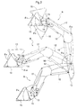
- the front loader B includes right and left fixed brackets 10 detachably mounted on corresponding support brackets 7, right and left booms 12 vertically pivotally connected to the corresponding fixed brackets 10 via a first support shaft 11 which is oriented in the right/left direction, right and left pivot brackets 14 vertically pivotally connected to free ends of the corresponding booms 12 via a second support shaft 13 which is oriented in the right/left direction, a bucket 15 detachably attached to the right and left pivot brackets 14, hydraulic double-action type right and left boom cylinders 16 used as "boom actuators", hydraulic double-action type right and left bucket cylinders 17 used as "bucket actuators", a boom angle detector 18 for detecting a vertical pivot angle ( ⁇ a) of one of the right and left booms 12, a bucket angle detector 19 for detecting a vertical pivot angle ( ⁇ b) of the bucket 15 relative to the right and left booms 12, and so on.
- a boom angle detector 18 for detecting a vertical pivot angle ( ⁇ a) of one of the right and left boom
- the right and left boom cylinders 16 pivotally drive the corresponding booms 12 in the vertical direction about the first support shaft 11 relative to the tractor A.
- the right and left bucket cylinders 17 pivotally drive the bucket 15 together with the right and left pivot brackets 14 in the vertical direction about the second support shaft 13 relative to the respective booms 12.
- the boom angle detector 18 and the bucket angle detector 19 comprise rotary type potentiometers in this implementation.
- the tractor A includes a valve unit 20 for controlling flow of oil to the right and left boom cylinders 16 and the right and left bucket cylinders 17 and an electronic control unit (“LD-ECU" hereinafter) 21 for the front loader configured to control operations of the right and left boom cylinders 16 and the right and left bucket cylinders 17 via the valve control unit 20.
- a valve unit 20 for controlling flow of oil to the right and left boom cylinders 16 and the right and left bucket cylinders 17 and an electronic control unit (“LD-ECU" hereinafter) 21 for the front loader configured to control operations of the right and left boom cylinders 16 and the right and left bucket cylinders 17 via the valve control unit 20.
- L-ECU electronice control unit
- the hydraulic control unit (valve unit) 20 includes an electronic control valve for the boom configured to control flow of oil fed to the right and left boom cylinders 16, an electronic control valve for the bucket configured to control flow of oil fed to the right and left bucket cylinders 17, etc.
- the LD-ECU 21 comprises a microcomputer having such components as a CPU, an EEPROM, etc. And, this LD-ECU 21 includes a manual controlling section 22 enabling manual operations of the right and left booms 12 and the bucket 15, a calculating section 23 for effecting various calculations, a storage section 24 for storing various kinds of data, a setting section 25 for setting a limit scoop angle of the bucket, a ground angle maintaining controlling section 26 for effecting ground angle maintaining control for maintaining a ground pivot angle ( ⁇ c) of the bucket 15 constant, and so on.
- a manual controlling section 22 enabling manual operations of the right and left booms 12 and the bucket 15
- a calculating section 23 for effecting various calculations
- a storage section 24 for storing various kinds of data
- a setting section 25 for setting a limit scoop angle of the bucket
- a ground angle maintaining controlling section 26 for effecting ground angle maintaining control for maintaining a ground pivot angle ( ⁇ c) of the bucket 15 constant, and so on.
- the manual controlling section 22 effects a manual operation control for controlling operations of the right and left boom cylinders 16 and the right and left bucket cylinders 17, in response to an operational instruction outputted from an instruction operational tool 32 for operating the front loader, comprised of a cross-pivoting, neutral-return type operational lever 30 provided in the riding driver's section 4 for operating the front loader and a lever operation detector 31 for detecting an operated position of the operational lever 30.
- an operational instruction outputted from the instruction operational tool 32 is an operational instruction for boom elevation
- the right and left boom cylinders 16 are extended to pivot the right and left booms 12 upwards.
- the operational instruction outputted from the instruction operational tool 32 is an operational instruction for boom lowering
- the right and left boom cylinders 16 are contracted to pivot the right and left booms 12 downwards.
- the operational instruction outputted from the instruction operational tool 32 is an operational instruction for bucket elevation, during continuation of the output of this operational instruction, the right and left bucket cylinders 17 are contracted to pivot the bucket 15 upwards (scooping pivot movement).
- the operational instruction outputted from the instruction operational tool 32 is an operational instruction for bucket lowering
- the right and left bucket cylinders 17 are extended to pivot the bucket 15 downwards (dumping pivot movement).
- output of any operational instruction from the instruction operational tool 32 is stopped, during continuation of this stop of output, extending operations of the right and left boom cylinders 16 and the right and left bucket cylinders 17 are stopped in order to stop any vertical pivotal movements of the right and left booms 12 and the bucket 15.
- the lever operation detector 31 can employ e.g. a plurality of switches for detecting the pivotal operations of the operational lever 30 to the various operated positions, or a rotary potentiometer for detecting a pivotal operation of the operational lever 30 in the front/rear direction in combination with a further rotary potentiometer for detecting a pivotal operation of the operational lever 30 in the right/left direction.
- the calculating section 23 calculates a ground pivot angle ( ⁇ c) of the bucket 15 based on an output from the boom angle detector 18 and an output from the bucket angle detector 19 and then outputs this calculation result to the storage section 24, the ground angle maintaining controlling section 26, and the scoop angle limit controlling section 27, etc.
- the storage section 24 stores the ground pivot angle ( ⁇ c) of the bucket 15 outputted from the calculating section 23 as a control target angle ( ⁇ co) if a setting switch 32 for setting control target angle provided in the riding driver's section 4 was depressed. More particularly, if the operational lever 30 was operated to actuate the right and left boom cylinders 16 and the right and left bucket cylinders 17 to operate the bucket 15 to a desired ground pivot angle ( ⁇ c) and then the setting switch 32 was depressed, this ground pivot angle ( ⁇ c) of the bucket 15 can be stored as the control target angle ( ⁇ co) for ground angle maintaining control in the storage section 24. Meanwhile, Fig. 2 illustrates a condition wherein the control target angle ( ⁇ co) for ground angle maintaining control is set to an angle for placing the bottom face of the bucket 15 horizontal.
- elevation restricted angles ( ⁇ bb) set slightly smaller, by a set angle (e.g. 2 degrees) than elevation limit angles ( ⁇ ba) of the bucket 15 and lowering restricted angles ( ⁇ bd) set slightly smaller, by a set angle (e.g. 2 degrees) than lowering limit angles ( ⁇ bc) of the bucket 15.
- the ground angle maintaining controlling section 26 effects ground angle maintaining control in case an instruction switch 34 for ground angle maintaining control provided in the riding driver's section 4 is depressed during stop of execution of the ground angle maintaining control. Also, this ground angle maintaining control is terminated if the instruction switch 34 for ground angle maintaining control is depressed during execution of ground angle maintaining control.
- the ground angle maintaining control firstly, based on an output from the boom angle detector 18, determination is made whether the vertical pivot angle ( ⁇ a) of the right and left booms 12 under stopped state thereof is within a set angle range (e.g. 2 degrees) from the elevation limit angles ( ⁇ ao) of the right and left booms 12 or not.
- a set angle range e.g. 2 degrees
- the instruction operational tool 32 when the instruction operational tool 32 outputs a boom lowering operational instruction and also when the instruction operational tool 32 outputs a boom elevation operational instruction in the case of the vertical pivot angle ( ⁇ a) of the right and left booms 12 under stopped state thereof being within the set angle from the elevation limit angles ( ⁇ bo) of the right and left booms 12, through combination of the feedforward control and the feedback control, the ground pivot angle ( ⁇ c) of the bucket 15 can be maintained at the control target angle ( ⁇ co) for the ground angle maintaining control (a desired ground pivot angle) with high precision, without inviting control delay in the bucket actuator.
- the instruction operational tool 32 when the instruction operational tool 32 outputs a boom elevation operational instruction and also when the instruction operational tool 32 outputs a boom elevation operational instruction in the case of the vertical pivot angle ( ⁇ a) of the right and left booms 12 under stopped state thereof being within the set angle from the elevation limit angles ( ⁇ bo) of the right and left booms 12, by not effecting any feedforward control, it is possible to avoid occurrence of inconvenience of the ground pivot angle ( ⁇ c) of the bucket 15 deviating significantly from the control target angle ( ⁇ co) for the ground angle maintaining control, due to preceding lowering pivotal movement of the bucket 15 in spite of the inability of the right and left booms 12 to pivotally move upwards.
- ground angle controlling section 26 in the ground angle maintaining control, in addition to the above-described control operations, based on an output from the bucket angle detector 18 and the elevation restricted angle ( ⁇ bb) and the lowering restricted angle ( ⁇ bd) both stored at the storage section 24, if it is detected that the vertical pivot angle ( ⁇ b) of the bucket 15 has reached a reduced speed angle ( ⁇ bx) smaller by a set angle (e.g.
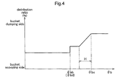
- a duty ratio for the electronic control valve for the bucket is changed so as to progressively decrease an oil distribution ratio for the right and left bucket cylinders 17 while the bucket 15 remains within a reduced speed range (H) from the reduced speed angle ( ⁇ bx) to the set angle (e.g. 5 degrees), thus progressively reducing the operational speed of the right and left bucket cylinders 17 to a target speed. Then, after passage through the reduced speed range (H), the operational speed will be maintained at the target speed.
- the storage section 24 may be configured to store relation data representing relation among the vertical pivot angles ( ⁇ a) of the booms 12, the elevation restricted angles ( ⁇ cb) set slightly smaller, by a set angle than the elevation limit angles ( ⁇ ca) of the bucket 15 relative to the ground pivot angles ( ⁇ c) of the bucket 15, and the lowering restricted angles ( ⁇ bd) set slightly smaller, by a set angle than the lowering limit angles ( ⁇ cc) of the bucket 15.
- a setting section may be provided for setting the elevation restricted angle ( ⁇ cb) and the lowering restricted angle ( ⁇ bd) of the bucket 15 in accordance with the vertical pivot angle ( ⁇ a) of the booms 12, based on such relation data and an output from the boom angle detector 18.
- the ground angle maintaining controlling section 26 detects that the vertical pivot angle ( ⁇ b) of the bucket 15 has reached the elevation restricted angle ( ⁇ cb) or the lowering restricted angle ( ⁇ cd)
- the right and left bucket cylinders 17 may be stopped automatically.
- the present invention is applicable to a front loader to be mounted on a traveling vehicle body such as a tractor.
Landscapes
- Engineering & Computer Science (AREA)
- Mechanical Engineering (AREA)
- Mining & Mineral Resources (AREA)
- Civil Engineering (AREA)
- General Engineering & Computer Science (AREA)
- Structural Engineering (AREA)
- Operation Control Of Excavators (AREA)
- Control Of Position, Course, Altitude, Or Attitude Of Moving Bodies (AREA)
- Forklifts And Lifting Vehicles (AREA)
Abstract
Description
- The present invention relates to a front loader including a boom actuator configured to pivotally drive a boom along a vertical direction relative to a traveling vehicle body about a first pivot axis which is oriented along a right/left direction, and a bucket actuator configured to pivotally drive a bucket along the vertical direction relative to the boom about a second pivot axis which is oriented along the right/left direction.
- According to a known front loader of the above-described type, a control apparatus is equipped with a velocity controlling means configured such that an angular velocity of the boom at the time of manual control is determined based on a signal from a boom sensor, a target angular velocity required for maintaining the bucket under a specified posture relative to the vehicle body is obtained based on the result of the above determination, and an operational speed of the bucket actuator is controlled such that this target angular velocity may be obtained by a bucket sensor (see Japanese Unexamined Patent Application Publication No.
10-245866 - With the above-described configuration, since the operational speed of the bucket actuator is controlled, posture correction of the bucket relative to a vertical pivotal movement of the boom can be effected in a favorable manner for the purpose of maintaining a ground pivot angle (pivot angle relative to the ground surface) of the bucket constant, irrespective of a vertical pivotal movement of the boom.
- However, since the operational speed of the bucket actuator is controlled based on an angular velocity of the boom detected by the boom sensor, the configuration is still unable to provide solution to a control delay which occurs in the posture correction of the bucket relative to the vertical pivotal movement of the boom. Thus, there remains room for improvement in the respect of maintaining a ground pivot angle of the bucket constant with high precision.
- In view of the above, there still exists a need for a front loader capable of maintaining a ground pivot angle of the bucket constant with high precision.
- According to the present invention, a front loader comprises:
- a boom actuator configured to pivotally drive a boom along a vertical direction relative to a traveling vehicle body about a first pivot axis which is oriented along a right/left direction;
- a bucket actuator configured to pivotally drive a bucket along the vertical direction relative to the boom about a second pivot axis which is oriented along the right/left direction;
- a boom angle detector for detecting a vertical pivot angle of the boom;
- a bucket angle detector for detecting a vertical pivot angle of the bucket relative to the boom;
- a calculating section for calculating a ground pivot angle (i.e. pivot angle relative to the ground surface) of the bucket based on an output from the boom angle detector and an output from the bucket angle detector;
- a manual controlling section for controlling operations of the boom actuator and the bucket actuator based on an operational instruction outputted from an instruction operational tool; and
- a ground angle maintaining controlling section for controlling the operation of the bucket actuator based on an output from the calculating section such that a ground pivot angle of the bucket may be maintained constant irrespective of any vertical pivotal movement of the boom;
- wherein the ground angle maintaining controlling section is configured such that:
- determination of whether a vertical pivot angle of the boom is within a set angle range measured from an elevation limit angle of the boom or not is made under a stopped state of the boom;
- when the instruction operational tool outputs an operational instruction for boom lowering, irrespective of result of said determination, based on this operational instruction, an elevation control operation for the bucket actuator is initiated, prior to initiation of a lowering control operation for the boom actuator by the manual controlling section;
- when the instruction operational tool outputs an operational instruction for boom elevation,
- if the determination results indicates the vertical pivot angle being outside said set angle range, based on said operational instruction, a lowering control operation for the bucket actuator is initiated, prior to initiation of an elevation control operation for the boom actuator by the manual controlling section;
- whereas, if the determination results indicates the vertical pivot angle being within said set angle range, the lowering control operation for the bucket actuator is not effected.
- With the above-described configuration, when the boom is to be pivotally lowered, the ground angle maintaining controlling section effects a feedforward control effected based on an operational instruction for boom lowering outputted from the instruction operational tool for initiating an elevation control operation for the bucket actuator prior to initiation of a lowering control operation for the boom actuator by the manual controlling section and effects also a feedback control effected based on an output from the calculating section for controlling operation of the bucket actuator so as to maintain the ground pivot angle of the bucket constant, irrespective of any vertical pivotal movement of the boom.
- Also, when the boom is to be pivotally elevated when the vertical pivot angle of the boom under its stopped state is outside the set angle range measured from an elevation limit angle of the boom, the ground angle maintaining controlling section effects a feedforward control effected based on an operational instruction for boom elevation outputted from the instruction operational tool for initiating a lowering control operation for the bucket actuator prior to initiation of an elevation control operation for the boom actuator by the manual controlling section and effects also the feedback control effected based on an output from the calculating section for controlling operation of the bucket actuator so as to maintain the ground pivot angle of the bucket constant, irrespective of any vertical pivotal movement of the boom.
- Further, if a pivotal elevation of the boom is attempted when the vertical pivot angle of the boom under its stopped state is within the set angle range, the ground angle maintaining controlling section effects no control operation for the bucket actuator.
- Namely, in the case of pivotal lowering of the boom and also in the case of pivotal elevation of the boom when the vertical pivot angle of the boom under its stopped state is outside the set angle range, through combination of the feedforward control and the feedback control, the ground pivot angle of the bucket can be maintained constant with high precision, without inviting control delay in the bucket actuator.
- Further, in the case of pivotal elevation of the boom being attempted when the vertical pivot angle of the boom under its stopped state is within the set angle range, no feedforward control is effected. With this, it is possible to avoid occurrence of inconvenience of inability to maintain the ground pivot angle of the bucket constant due to preceding pivotal lowering of the bucket in spite of the boom being hardly pivotable upwards as being located within the set angle range measured from the elevation limit angle of the boom.
- Consequently, it is possible to maintain a ground pivot angle of the bucket constant with higher precision, irrespective of any vertical pivotal movement of the boom.
- In the above configuration, preferably, a feedforward control is effected based on an operational instruction for boom lowering outputted from the instruction operational tool and then shift is made from the feedforward control to the feedback control. With this configuration, at the early stage, by the feedforward control, the bucket can be maintained to a desired ground pivot angle speedily. And, thereafter, by the feedback control, based on the actual ground pivot angle of the bucket, the ground pivot angle of the bucket can be maintained reliably.
- In the above configuration, preferably, if the determination results indicate the vertical pivot angle being outside the set angle range, based on an operational instruction for boom elevation outputted from the instruction operational tool, the feedforward control is effected and then shift is made from the feedforward control to the feedback control. With this configuration, at the early stage, by the feedforward control, the bucket can be maintained to a desired ground pivot angle speedily. And, thereafter, by the feedback control, based on the actual ground pivot angle of the bucket, the ground pivot angle of the bucket can be maintained reliably.
- In the above configuration, preferably, a storage section is provided for storing information relating to target ground pivot angles for ground angle maintaining control. With this configuration, the ground angle maintaining controlling section can execute the ground angle maintaining control in a reliable manner based on the information stored in the storage section.
- In the above configuration, preferably, a ground pivot angle outputted from the calculating section when a predetermined operational tool is operated by a rider's operation on this operational tool is stored as the target ground pivot angle in the storage section. With this configuration, a target ground pivot angle can be set by a simple operation.
- In the above configuration, preferably, the ground angle maintaining controlling section executes the control such that the ground pivot angle may be confined within a non-sensitive range which is a predetermined range from the target ground pivot angle. With this configuration, it becomes possible to reduce the control frequency, thereby smoothing the bucket movement.
- In the above, the instruction operational tool comprises an operational lever. Preferably, the operational lever comprises a cross-pivoting operational lever. The operational lever can comprise a neutral-return type operational lever. Further, the instruction operational tool comprises a lever operation detector for detecting an operated position of the operational lever. Preferably, the lever operation detector comprises a plurality of switches for detecting pivotal operations of the operational lever to respective operational positions of the operational lever. Alternatively, the lever operation detector can comprise a rotary potentiometer. Preferably, the lever operation detector comprises a rotary potentiometer for detecting a pivotal operation in a front/rear direction and a rotary potentiometer for detecting a pivotal operation in the right/left direction.
-
- [
Fig. 1 ] is a left side view of a tractor mounting a front loader, - [
Fig. 2 ] is a left side view showing an operative condition of the front loader, - [
Fig. 3 ] is a block diagram showing a controlling configuration relating to the front loader, and - [
Fig. 4 ] is a view showing operational speeds at the time of automatic stop of bucket. - Next, as an exemplary implementation of the present invention, a front loader relating to the present invention will be described with reference to the accompanying drawings by way of a first embodiment wherein the front loader is mounted to a tractor as an example of a traveling vehicle body.
- As shown in
Fig. 1 , a tractor A as an example of a traveling vehicle body in the first embodiment includes, on the front side of avehicle body frame 1, anengine section 2 and right and leftfront wheels 3, etc. The tractor A also includes, on the rear side of thevehicle body frame 1, acabin 5 forming a riding driver'ssection 4 and right and leftrear wheels 8, etc. At a front/rear intermediate portion of thevehicle body frame 1, there are mounted right and left support brackets 7 allowing mounting of a front loader B. The riding driver'ssection 4 includes asteering wheel 8, a driver'sseat 9, etc. - As shown in
Figs. 1 through 3 , the front loader B includes right and left fixedbrackets 10 detachably mounted on corresponding support brackets 7, right andleft booms 12 vertically pivotally connected to the correspondingfixed brackets 10 via afirst support shaft 11 which is oriented in the right/left direction, right andleft pivot brackets 14 vertically pivotally connected to free ends of thecorresponding booms 12 via asecond support shaft 13 which is oriented in the right/left direction, abucket 15 detachably attached to the right andleft pivot brackets 14, hydraulic double-action type right andleft boom cylinders 16 used as "boom actuators", hydraulic double-action type right andleft bucket cylinders 17 used as "bucket actuators", aboom angle detector 18 for detecting a vertical pivot angle (θa) of one of the right andleft booms 12, abucket angle detector 19 for detecting a vertical pivot angle (θb) of thebucket 15 relative to the right andleft booms 12, and so on. - The right and
left boom cylinders 16 pivotally drive thecorresponding booms 12 in the vertical direction about thefirst support shaft 11 relative to the tractor A. The right andleft bucket cylinders 17 pivotally drive thebucket 15 together with the right andleft pivot brackets 14 in the vertical direction about thesecond support shaft 13 relative to therespective booms 12. Theboom angle detector 18 and thebucket angle detector 19 comprise rotary type potentiometers in this implementation. - As shown in
Fig. 3 , the tractor A includes avalve unit 20 for controlling flow of oil to the right andleft boom cylinders 16 and the right andleft bucket cylinders 17 and an electronic control unit ("LD-ECU" hereinafter) 21 for the front loader configured to control operations of the right andleft boom cylinders 16 and the right andleft bucket cylinders 17 via thevalve control unit 20. - Though not shown, the hydraulic control unit (valve unit) 20 includes an electronic control valve for the boom configured to control flow of oil fed to the right and left
boom cylinders 16, an electronic control valve for the bucket configured to control flow of oil fed to the right and leftbucket cylinders 17, etc. - As shown in
Fig. 2 andFig. 3 , the LD-ECU 21 comprises a microcomputer having such components as a CPU, an EEPROM, etc. And, this LD-ECU 21 includes a manual controllingsection 22 enabling manual operations of the right and leftbooms 12 and thebucket 15, a calculatingsection 23 for effecting various calculations, astorage section 24 for storing various kinds of data, a setting section 25 for setting a limit scoop angle of the bucket, a ground angle maintaining controllingsection 26 for effecting ground angle maintaining control for maintaining a ground pivot angle (θc) of thebucket 15 constant, and so on. - The
manual controlling section 22 effects a manual operation control for controlling operations of the right and leftboom cylinders 16 and the right and leftbucket cylinders 17, in response to an operational instruction outputted from an instructionoperational tool 32 for operating the front loader, comprised of a cross-pivoting, neutral-return typeoperational lever 30 provided in the riding driver'ssection 4 for operating the front loader and alever operation detector 31 for detecting an operated position of theoperational lever 30. - In the manual operation control, if an operational instruction outputted from the instruction
operational tool 32 is an operational instruction for boom elevation, during continuation of the output of this operational instruction, the right and leftboom cylinders 16 are extended to pivot the right and leftbooms 12 upwards. Whereas, if the operational instruction outputted from the instructionoperational tool 32 is an operational instruction for boom lowering, during continuation of the output of this operational instruction, the right and leftboom cylinders 16 are contracted to pivot the right and leftbooms 12 downwards. Further, if the operational instruction outputted from the instructionoperational tool 32 is an operational instruction for bucket elevation, during continuation of the output of this operational instruction, the right and leftbucket cylinders 17 are contracted to pivot thebucket 15 upwards (scooping pivot movement). Whereas, if the operational instruction outputted from the instructionoperational tool 32 is an operational instruction for bucket lowering, during continuation of the output of this operational instruction, the right and leftbucket cylinders 17 are extended to pivot thebucket 15 downwards (dumping pivot movement). Moreover, if output of any operational instruction from the instructionoperational tool 32 is stopped, during continuation of this stop of output, extending operations of the right and leftboom cylinders 16 and the right and leftbucket cylinders 17 are stopped in order to stop any vertical pivotal movements of the right and leftbooms 12 and thebucket 15. - The
lever operation detector 31 can employ e.g. a plurality of switches for detecting the pivotal operations of theoperational lever 30 to the various operated positions, or a rotary potentiometer for detecting a pivotal operation of theoperational lever 30 in the front/rear direction in combination with a further rotary potentiometer for detecting a pivotal operation of theoperational lever 30 in the right/left direction. - The calculating
section 23 calculates a ground pivot angle (θc) of thebucket 15 based on an output from theboom angle detector 18 and an output from thebucket angle detector 19 and then outputs this calculation result to thestorage section 24, the ground angle maintaining controllingsection 26, and the scoop angle limit controlling section 27, etc. - The
storage section 24 stores the ground pivot angle (θc) of thebucket 15 outputted from the calculatingsection 23 as a control target angle (θco) if a settingswitch 32 for setting control target angle provided in the riding driver'ssection 4 was depressed. More particularly, if theoperational lever 30 was operated to actuate the right and leftboom cylinders 16 and the right and leftbucket cylinders 17 to operate thebucket 15 to a desired ground pivot angle (θc) and then the settingswitch 32 was depressed, this ground pivot angle (θc) of thebucket 15 can be stored as the control target angle (θco) for ground angle maintaining control in thestorage section 24. Meanwhile,Fig. 2 illustrates a condition wherein the control target angle (θco) for ground angle maintaining control is set to an angle for placing the bottom face of thebucket 15 horizontal. - Further, there are also stored elevation restricted angles (θbb) set slightly smaller, by a set angle (e.g. 2 degrees) than elevation limit angles (θba) of the
bucket 15 and lowering restricted angles (θbd) set slightly smaller, by a set angle (e.g. 2 degrees) than lowering limit angles (θbc) of thebucket 15. - As shown in
Figs. 2 through 4 , the ground angle maintaining controllingsection 26 effects ground angle maintaining control in case aninstruction switch 34 for ground angle maintaining control provided in the riding driver'ssection 4 is depressed during stop of execution of the ground angle maintaining control. Also, this ground angle maintaining control is terminated if theinstruction switch 34 for ground angle maintaining control is depressed during execution of ground angle maintaining control. - In the ground angle maintaining control, firstly, based on an output from the
boom angle detector 18, determination is made whether the vertical pivot angle (θa) of the right and leftbooms 12 under stopped state thereof is within a set angle range (e.g. 2 degrees) from the elevation limit angles (θao) of the right and leftbooms 12 or not. - Thereafter, when the instruction
operational tool 32 outputs a boom lowering operational instruction, irrespectively of the result of the above determination, before the manual controllingsection 22 initiates a lowering control operation for the right and leftboom cylinders 16 based on the above operational instruction, an elevation control operation for the right and leftbucket cylinders 17 is initiated. And, based on the control target angle (θco) for ground angle control stored in thestorage section 24 and the control target angle (θco) for thebucket 15 outputted from the calculatingsection 23, operations of the right and leftbucket cylinders 17 are controlled such that the ground pivot angle (θc) of thebucket 15 may agree to the control target angle (θco) for the ground angle control (be present within a non-sensitive range of the control target angle (θco)), irrespective of lowering pivotal movement of the right and leftbooms 12. - Conversely, when the instruction
operational tool 32 outputs a boom elevation operational instruction, the result of the above determination is reflected and if the determination result indicates the angle being outside the set angle range, then, based on this operational instruction, lowering control operation for the right and leftbucket cylinders 17 will be initiated before the manual controllingsection 22 initiates elevation controlling operation for the right and leftboom cylinders 16 based on the above operational instruction. - Moreover, if the determination result indicates the angle being within the set angle range, then, no control operation for the right and left
bucket cylinders 17 is effected and thebucket 15 is maintained under its current pivotal posture. - Namely, when the instruction
operational tool 32 outputs a boom lowering operational instruction and also when the instructionoperational tool 32 outputs a boom elevation operational instruction in the case of the vertical pivot angle (θa) of the right and leftbooms 12 under stopped state thereof being within the set angle from the elevation limit angles (θbo) of the right and leftbooms 12, through combination of the feedforward control and the feedback control, the ground pivot angle (θc) of thebucket 15 can be maintained at the control target angle (θco) for the ground angle maintaining control (a desired ground pivot angle) with high precision, without inviting control delay in the bucket actuator. - Further, when the instruction
operational tool 32 outputs a boom elevation operational instruction and also when the instructionoperational tool 32 outputs a boom elevation operational instruction in the case of the vertical pivot angle (θa) of the right and leftbooms 12 under stopped state thereof being within the set angle from the elevation limit angles (θbo) of the right and leftbooms 12, by not effecting any feedforward control, it is possible to avoid occurrence of inconvenience of the ground pivot angle (θc) of thebucket 15 deviating significantly from the control target angle (θco) for the ground angle maintaining control, due to preceding lowering pivotal movement of thebucket 15 in spite of the inability of the right and leftbooms 12 to pivotally move upwards. - With the ground
angle controlling section 26, in the ground angle maintaining control, in addition to the above-described control operations, based on an output from thebucket angle detector 18 and the elevation restricted angle (θbb) and the lowering restricted angle (θbd) both stored at thestorage section 24, if it is detected that the vertical pivot angle (θb) of thebucket 15 has reached a reduced speed angle (θbx) smaller by a set angle (e.g. 10 degrees) than the elevation restricted angle (θbb) or the lowering restricted angle (θbd); then, on priority over the control operation of the manual controllingsection 22 based on an operational instruction from theinstruction operating tool 32, a duty ratio for the electronic control valve for the bucket is changed so as to progressively decrease an oil distribution ratio for the right and leftbucket cylinders 17 while thebucket 15 remains within a reduced speed range (H) from the reduced speed angle (θbx) to the set angle (e.g. 5 degrees), thus progressively reducing the operational speed of the right and leftbucket cylinders 17 to a target speed. Then, after passage through the reduced speed range (H), the operational speed will be maintained at the target speed. - Thereafter, when it is detected that the vertical pivot angle (θb) of the
bucket 15 has reached the elevation restricted angle (θbb) or the lowering restricted angle (θbd); then, the right and leftbucket cylinders 17 will be automatically stopped, whereby the vertical pivot angle (θb) of thebucket 15 will be maintained at the elevation restricted angle (θbb) or the lowering restricted angle (θbd). - With the above-described arrangement, in the ground angle maintaining control, it is possible to avoid occurrence of inconvenience of a relief valve provided in the
valve unit 20 being activated to reduce the amount of oil fed to the right and leftboom cylinders 16, thus inadvertently reducing the driving speed of thebooms 12, due to the vertical pivot angle (θb) of thebucket 15 reaching the elevation restricted angle (θba) or the lowering restricted angle (θbc). - Moreover, as the operational speed of the right and left
bucket cylinders 17 is progressively reduced prior to the automatic stop, it is possible to restrict occurrence of shock at the time of automatic stop, thus allowing increase in stopping precision of the bucket at the elevation restricted angle (θbb) or the lowering restricted angle (θbd). - Though not shown, the
storage section 24 may be configured to store relation data representing relation among the vertical pivot angles (θa) of thebooms 12, the elevation restricted angles (θcb) set slightly smaller, by a set angle than the elevation limit angles (θca) of thebucket 15 relative to the ground pivot angles (θc) of thebucket 15, and the lowering restricted angles (θbd) set slightly smaller, by a set angle than the lowering limit angles (θcc) of thebucket 15. And, a setting section may be provided for setting the elevation restricted angle (θcb) and the lowering restricted angle (θbd) of thebucket 15 in accordance with the vertical pivot angle (θa) of thebooms 12, based on such relation data and an output from theboom angle detector 18. And, when the ground angle maintaining controllingsection 26 detects that the vertical pivot angle (θb) of thebucket 15 has reached the elevation restricted angle (θcb) or the lowering restricted angle (θcd), the right and leftbucket cylinders 17 may be stopped automatically. -
- [1] The traveling vehicle body A can be a vehicle dedicated to loader operations, a loader-mower vehicle mounting the front loader B and a mower, a loader-excavator vehicle mounting the front loader B and a backhoe.
- [2] The
boom actuator 16 and thebucket actuator 17 can be hydraulic motors or the like. - [3] The instruction
operational tool 32 can comprise an operational tool for the boom only and a further operational tool for the bucket only. Further, the instructionoperational tool 32 can comprise a switch for instructing an upward pivot movement of the boom 12 a switch for instructing a downward pivot movement of theboom 12, a switch for instructing a scooping pivot movement of thebucket 15 and a switch for instructing a dumping pivot movement of thebucket 15. - [4] The
boom angle detector 18 can comprise a sliding type potentiometer configured to detect an extended/contracted length of theboom cylinder 16 as a vertical pivot angle (θa) of theboom 12. Further, thebucket angle detector 19 can comprise a sliding type potentiometer configured to detect an extended/contracted length of thebucket cylinder 17 as a vertical pivot angle (θb) of thebucket 15. - [5] The set angle from the elevation restricted angle (θao) of the
boom 12 where the ground angle maintaining controllingsection 26 effects no control operation for thebucket actuator 17 can vary in many ways as long as no inconvenience occurs in maintaining the ground pivot angle (θc) of thebucket 15 constant. For instance, the set angle can be 3 degrees, 4 degrees, etc. - The present invention is applicable to a front loader to be mounted on a traveling vehicle body such as a tractor.
Claims (1)
- A front loader characterized in that it comprises:a boom actuator (16) configured to pivotally drive a boom (12) along a vertical direction relative to a traveling vehicle body about a first pivot axis which is oriented along a right/left direction;a bucket actuator (17) configured to pivotally drive a bucket (15) along the vertical direction relative to the boom (12) about a second pivot axis which is oriented along the right/left direction;a boom angle detector (18) for detecting a vertical pivot angle of the boom (12);a bucket angle detector (19) for detecting a vertical pivot angle of the bucket (15) relative to the boom (12);a calculating section (23) for calculating a ground pivot angle (i.e. pivot angle relative to the ground surface) of the bucket (15) based on an output from the boom angle detector (18) and an output from the bucket angle detector (19);a manual controlling section (22) for controlling operations of the boom actuator (16) and the bucket actuator (17) based on an operational instruction outputted from an instruction operational tool (32); anda ground angle maintaining controlling section (26) for controlling the operation of the bucket actuator (17) based on an output from the calculating section (23) such that a ground pivot angle of the bucket (15) may be maintained constant irrespective of any vertical pivotal movement of the boom (12);wherein the ground angle maintaining controlling section (26) is configured such that:determination of whether a vertical pivot angle of the boom (12) is within a set angle range measured from an elevation limit angle of the boom (12) or not is made under a stopped state of the boom (12);when the instruction operational tool (32) outputs an operational instruction for boom lowering, irrespective of result of said determination, based on this operational instruction, an elevation control operation for the bucket actuator (17) is initiated, prior to initiation of a lowering control operation for the boom actuator (16) by the manual controlling section (22);when the instruction operational tool (32) outputs an operational instruction for boom elevation,
if the determination results indicates the vertical pivot angle being outside said set angle range, based on said operational instruction, a lowering control operation for the bucket actuator (17) is initiated, prior to initiation of an elevation control operation for the boom actuator (16) by the manual controlling section (22);
whereas, if the determination results indicates the vertical pivot angle being within said set angle range, the lowering control operation for the bucket actuator (17) is not effected.
Applications Claiming Priority (4)
| Application Number | Priority Date | Filing Date | Title |
|---|---|---|---|
| JP2014067009A JP6223253B2 (en) | 2014-03-27 | 2014-03-27 | Front loader |
| JP2014072107A JP6113103B2 (en) | 2014-03-31 | 2014-03-31 | Front loader |
| JP2014072108A JP6223259B2 (en) | 2014-03-31 | 2014-03-31 | Front loader |
| JP2014072106A JP6223258B2 (en) | 2014-03-31 | 2014-03-31 | Work vehicle |
Publications (3)
| Publication Number | Publication Date |
|---|---|
| EP2924176A2 true EP2924176A2 (en) | 2015-09-30 |
| EP2924176A3 EP2924176A3 (en) | 2015-10-21 |
| EP2924176B1 EP2924176B1 (en) | 2016-12-07 |
Family
ID=52686265
Family Applications (4)
| Application Number | Title | Priority Date | Filing Date |
|---|---|---|---|
| EP15160059.0A Active EP2924177B1 (en) | 2014-03-27 | 2015-03-20 | Work vehicle |
| EP15160095.4A Active EP2924178B1 (en) | 2014-03-27 | 2015-03-20 | Front loader |
| EP15160058.2A Active EP2924176B1 (en) | 2014-03-27 | 2015-03-20 | Front loader |
| EP15160054.1A Active EP2924175B1 (en) | 2014-03-27 | 2015-03-20 | Front loader |
Family Applications Before (2)
| Application Number | Title | Priority Date | Filing Date |
|---|---|---|---|
| EP15160059.0A Active EP2924177B1 (en) | 2014-03-27 | 2015-03-20 | Work vehicle |
| EP15160095.4A Active EP2924178B1 (en) | 2014-03-27 | 2015-03-20 | Front loader |
Family Applications After (1)
| Application Number | Title | Priority Date | Filing Date |
|---|---|---|---|
| EP15160054.1A Active EP2924175B1 (en) | 2014-03-27 | 2015-03-20 | Front loader |
Country Status (2)
| Country | Link |
|---|---|
| US (2) | US9238899B2 (en) |
| EP (4) | EP2924177B1 (en) |
Families Citing this family (16)
| Publication number | Priority date | Publication date | Assignee | Title |
|---|---|---|---|---|
| CL2012000933A1 (en) | 2011-04-14 | 2014-07-25 | Harnischfeger Tech Inc | A method and a cable shovel for the generation of an ideal path, comprises: an oscillation engine, a hoisting engine, a feed motor, a bucket for digging and emptying materials and, positioning the shovel by means of the operation of the lifting motor, feed motor and oscillation engine and; a controller that includes an ideal path generator module. |
| US9206587B2 (en) | 2012-03-16 | 2015-12-08 | Harnischfeger Technologies, Inc. | Automated control of dipper swing for a shovel |
| US9238899B2 (en) * | 2014-03-27 | 2016-01-19 | Kubota Corporation | Front loader |
| JP6591531B2 (en) * | 2015-03-27 | 2019-10-16 | 住友建機株式会社 | Excavator |
| JP6884702B2 (en) * | 2015-09-16 | 2021-06-09 | 住友重機械工業株式会社 | Excavator |
| CN105544632B (en) * | 2016-01-29 | 2017-09-29 | 徐工集团工程机械股份有限公司科技分公司 | It is a kind of to be used to control the system that loading shovel is laid flat automatically |
| JP6208899B1 (en) * | 2016-10-28 | 2017-10-04 | 株式会社小松製作所 | Loading machine control system and loading machine control method |
| JP6815834B2 (en) * | 2016-11-01 | 2021-01-20 | 株式会社小松製作所 | Work vehicle control system, control method, and work vehicle |
| DE112016000156B4 (en) * | 2016-11-29 | 2021-12-30 | Komatsu Ltd. | Control device for a construction machine and method for controlling a construction machine |
| US10179986B1 (en) | 2017-11-01 | 2019-01-15 | Richard A Morrison, Sr. | Plow conversion kit |
| JP7039451B2 (en) * | 2018-12-25 | 2022-03-22 | 株式会社クボタ | Working machine |
| US10988913B2 (en) * | 2019-02-21 | 2021-04-27 | Deere & Company | Blade for work vehicle |
| US11078648B2 (en) * | 2019-02-22 | 2021-08-03 | Caterpillar Inc. | Grade control for machines with buckets |
| CN113631776B (en) * | 2019-03-28 | 2023-02-17 | 住友建机株式会社 | Excavator and construction system |
| US11549236B1 (en) | 2021-06-16 | 2023-01-10 | Cnh Industrial America Llc | Work vehicle with improved bi-directional self-leveling functionality and related systems and methods |
| US20230064337A1 (en) | 2021-08-26 | 2023-03-02 | Caterpillar Inc. | Methods and systems for implementing a lock-out command on lever machines |
Citations (1)
| Publication number | Priority date | Publication date | Assignee | Title |
|---|---|---|---|---|
| JPH10245866A (en) | 1997-03-06 | 1998-09-14 | Kubota Corp | Shovel device |
Family Cites Families (30)
| Publication number | Priority date | Publication date | Assignee | Title |
|---|---|---|---|---|
| US3713557A (en) * | 1970-07-27 | 1973-01-30 | Case Co J I | Method and apparatus for positioning bucket loader |
| JPH0724431Y2 (en) * | 1989-04-11 | 1995-06-05 | 株式会社クボタ | Boom type hydraulic working equipment hydraulic operating device |
| US5234312A (en) * | 1991-02-27 | 1993-08-10 | Toyo Umpanki Co., Ltd. | Loading unit attitude control system |
| JP3173896B2 (en) | 1992-11-09 | 2001-06-04 | 株式会社クボタ | Backhoe |
| JPH0724431A (en) | 1993-07-09 | 1995-01-27 | Nikkiso Co Ltd | Volume reducing device for pllastic container |
| JPH08302747A (en) * | 1995-04-29 | 1996-11-19 | Samsung Heavy Ind Co Ltd | Heavily equipped operating device having automatic horizontal adjustment fuction of attachment |
| JP2000096601A (en) * | 1998-09-25 | 2000-04-04 | Komatsu Ltd | Method and device for controlling angle of working machine |
| US7140830B2 (en) | 2003-01-14 | 2006-11-28 | Cnh America Llc | Electronic control system for skid steer loader controls |
| US8056674B2 (en) * | 2004-02-26 | 2011-11-15 | Jlg Industries, Inc. | Boom lift vehicle and method of controlling lifting functions |
| US7246684B2 (en) * | 2004-02-26 | 2007-07-24 | Jlg Industries, Inc. | Boom lift vehicle and method of controlling boom angles |
| US7059422B2 (en) * | 2004-04-26 | 2006-06-13 | Bobby Gene Burgin | Self-orienting loader bucket mechanism |
| JP2006152707A (en) | 2004-11-30 | 2006-06-15 | Iseki & Co Ltd | Front loader control device of working vehicle |
| US8065060B2 (en) * | 2006-01-18 | 2011-11-22 | The Board Of Regents Of The University And Community College System On Behalf Of The University Of Nevada | Coordinated joint motion control system with position error correction |
| DE102006044533A1 (en) | 2006-09-21 | 2008-04-03 | Wilhelm Stoll Maschinenfabrik Gmbh | Front loader with mechanical parallel guidance |
| US20100215469A1 (en) * | 2007-06-15 | 2010-08-26 | Boris Trifunovic | Electronic Parallel Lift And Return To Dig On A Backhoe Loader |
| US8500387B2 (en) * | 2007-06-15 | 2013-08-06 | Deere & Company | Electronic parallel lift and return to carry or float on a backhoe loader |
| US20100254793A1 (en) * | 2007-06-15 | 2010-10-07 | Boris Trifunovic | Electronic Anti-Spill |
| US7530185B2 (en) * | 2007-06-22 | 2009-05-12 | Deere & Company | Electronic parallel lift and return to carry on a backhoe loader |
| JP5114133B2 (en) | 2007-08-27 | 2013-01-09 | 株式会社クボタ | Front loader |
| US7949449B2 (en) * | 2007-12-19 | 2011-05-24 | Caterpillar Inc. | Constant work tool angle control |
| US9238903B2 (en) * | 2009-03-26 | 2016-01-19 | Komatsu Ltd. | Control method and control apparatus for work vehicle |
| JP5037561B2 (en) * | 2009-05-13 | 2012-09-26 | 株式会社小松製作所 | Work vehicle |
| US8594896B2 (en) | 2009-12-18 | 2013-11-26 | Caterpillar Sarl | Lift arm control system |
| JP5261419B2 (en) * | 2010-03-05 | 2013-08-14 | 株式会社小松製作所 | Work vehicle and control method of work vehicle |
| JP5405517B2 (en) | 2011-03-30 | 2014-02-05 | 株式会社クボタ | Front loader |
| WO2013040633A1 (en) * | 2011-09-20 | 2013-03-28 | Tech Mining Pty Ltd Acn 153 118 024 | Stress and/or accumulated damage monitoring system |
| US8706364B2 (en) * | 2012-03-30 | 2014-04-22 | Komatsu Ltd. | Wheel loader and method for controlling wheel loader |
| JP6223300B2 (en) | 2013-10-04 | 2017-11-01 | 株式会社クボタ | Front loader |
| DE112013000251B3 (en) * | 2013-11-26 | 2015-08-20 | Komatsu Ltd. | working vehicle |
| US9238899B2 (en) * | 2014-03-27 | 2016-01-19 | Kubota Corporation | Front loader |
-
2015
- 2015-03-17 US US14/659,991 patent/US9238899B2/en active Active
- 2015-03-19 US US14/662,493 patent/US9238900B2/en active Active
- 2015-03-20 EP EP15160059.0A patent/EP2924177B1/en active Active
- 2015-03-20 EP EP15160095.4A patent/EP2924178B1/en active Active
- 2015-03-20 EP EP15160058.2A patent/EP2924176B1/en active Active
- 2015-03-20 EP EP15160054.1A patent/EP2924175B1/en active Active
Patent Citations (1)
| Publication number | Priority date | Publication date | Assignee | Title |
|---|---|---|---|---|
| JPH10245866A (en) | 1997-03-06 | 1998-09-14 | Kubota Corp | Shovel device |
Also Published As
| Publication number | Publication date |
|---|---|
| EP2924177A3 (en) | 2015-10-28 |
| EP2924175B1 (en) | 2018-04-18 |
| EP2924178B1 (en) | 2018-05-16 |
| US9238900B2 (en) | 2016-01-19 |
| EP2924176A3 (en) | 2015-10-21 |
| EP2924177B1 (en) | 2018-05-16 |
| US9238899B2 (en) | 2016-01-19 |
| EP2924178A3 (en) | 2015-10-21 |
| US20150275471A1 (en) | 2015-10-01 |
| EP2924177A2 (en) | 2015-09-30 |
| EP2924176B1 (en) | 2016-12-07 |
| US20150275470A1 (en) | 2015-10-01 |
| EP2924175A3 (en) | 2015-10-14 |
| EP2924175A2 (en) | 2015-09-30 |
| EP2924178A2 (en) | 2015-09-30 |
Similar Documents
| Publication | Publication Date | Title |
|---|---|---|
| EP2924176B1 (en) | Front loader | |
| CN106661858B (en) | Wheel loader | |
| EP3128084B1 (en) | Work vehicle with improved implement position control and self-leveling functionality | |
| US7530185B2 (en) | Electronic parallel lift and return to carry on a backhoe loader | |
| JPWO2017115809A1 (en) | Excavator | |
| CN110382785B (en) | Working machine | |
| CN110291254B (en) | Excavator | |
| US20160251829A1 (en) | Work vehicle control method, work vehicle control device, and work vehicle | |
| CN111868333B (en) | Working machine | |
| US9617710B2 (en) | Work vehicle and method for controlling work vehicle | |
| JP7284019B2 (en) | System and method for controlling bulldozer | |
| US20230129066A1 (en) | Work machine and control method for work machine | |
| JP6223253B2 (en) | Front loader | |
| EP3907334A1 (en) | Work machine and work machine control method | |
| CN109689982B (en) | Construction machine | |
| JP6113103B2 (en) | Front loader | |
| JP6223258B2 (en) | Work vehicle | |
| EP3584376B1 (en) | Work vehicle and work vehicle control method | |
| WO2022255001A1 (en) | Work machine and method for controlling work machine | |
| US20240011253A1 (en) | Shovel and shovel control device | |
| JP5180900B2 (en) | Working machine control device for offset boom type hydraulic excavator | |
| JP6223259B2 (en) | Front loader | |
| JP2004239303A (en) | Drive control device for hydraulic cylinder of construction machine |
Legal Events
| Date | Code | Title | Description |
|---|---|---|---|
| PUAL | Search report despatched |
Free format text: ORIGINAL CODE: 0009013 |
|
| PUAI | Public reference made under article 153(3) epc to a published international application that has entered the european phase |
Free format text: ORIGINAL CODE: 0009012 |
|
| AK | Designated contracting states |
Kind code of ref document: A2 Designated state(s): AL AT BE BG CH CY CZ DE DK EE ES FI FR GB GR HR HU IE IS IT LI LT LU LV MC MK MT NL NO PL PT RO RS SE SI SK SM TR |
|
| AX | Request for extension of the european patent |
Extension state: BA ME |
|
| AK | Designated contracting states |
Kind code of ref document: A3 Designated state(s): AL AT BE BG CH CY CZ DE DK EE ES FI FR GB GR HR HU IE IS IT LI LT LU LV MC MK MT NL NO PL PT RO RS SE SI SK SM TR |
|
| AX | Request for extension of the european patent |
Extension state: BA ME |
|
| RIC1 | Information provided on ipc code assigned before grant |
Ipc: E02F 3/43 20060101AFI20150917BHEP |
|
| 17P | Request for examination filed |
Effective date: 20160226 |
|
| RBV | Designated contracting states (corrected) |
Designated state(s): AL AT BE BG CH CY CZ DE DK EE ES FI FR GB GR HR HU IE IS IT LI LT LU LV MC MK MT NL NO PL PT RO RS SE SI SK SM TR |
|
| GRAP | Despatch of communication of intention to grant a patent |
Free format text: ORIGINAL CODE: EPIDOSNIGR1 |
|
| INTG | Intention to grant announced |
Effective date: 20160721 |
|
| GRAS | Grant fee paid |
Free format text: ORIGINAL CODE: EPIDOSNIGR3 |
|
| GRAA | (expected) grant |
Free format text: ORIGINAL CODE: 0009210 |
|
| STAA | Information on the status of an ep patent application or granted ep patent |
Free format text: STATUS: THE PATENT HAS BEEN GRANTED |
|
| AK | Designated contracting states |
Kind code of ref document: B1 Designated state(s): AL AT BE BG CH CY CZ DE DK EE ES FI FR GB GR HR HU IE IS IT LI LT LU LV MC MK MT NL NO PL PT RO RS SE SI SK SM TR |
|
| REG | Reference to a national code |
Ref country code: GB Ref legal event code: FG4D |
|
| REG | Reference to a national code |
Ref country code: CH Ref legal event code: EP Ref country code: AT Ref legal event code: REF Ref document number: 851842 Country of ref document: AT Kind code of ref document: T Effective date: 20161215 |
|
| REG | Reference to a national code |
Ref country code: IE Ref legal event code: FG4D |
|
| REG | Reference to a national code |
Ref country code: DE Ref legal event code: R096 Ref document number: 602015000894 Country of ref document: DE |
|
| PG25 | Lapsed in a contracting state [announced via postgrant information from national office to epo] |
Ref country code: LV Free format text: LAPSE BECAUSE OF FAILURE TO SUBMIT A TRANSLATION OF THE DESCRIPTION OR TO PAY THE FEE WITHIN THE PRESCRIBED TIME-LIMIT Effective date: 20161207 |
|
| REG | Reference to a national code |
Ref country code: FR Ref legal event code: PLFP Year of fee payment: 3 |
|
| REG | Reference to a national code |
Ref country code: LT Ref legal event code: MG4D |
|
| REG | Reference to a national code |
Ref country code: NL Ref legal event code: MP Effective date: 20161207 |
|
| PG25 | Lapsed in a contracting state [announced via postgrant information from national office to epo] |
Ref country code: GR Free format text: LAPSE BECAUSE OF FAILURE TO SUBMIT A TRANSLATION OF THE DESCRIPTION OR TO PAY THE FEE WITHIN THE PRESCRIBED TIME-LIMIT Effective date: 20170308 Ref country code: NO Free format text: LAPSE BECAUSE OF FAILURE TO SUBMIT A TRANSLATION OF THE DESCRIPTION OR TO PAY THE FEE WITHIN THE PRESCRIBED TIME-LIMIT Effective date: 20170307 Ref country code: LT Free format text: LAPSE BECAUSE OF FAILURE TO SUBMIT A TRANSLATION OF THE DESCRIPTION OR TO PAY THE FEE WITHIN THE PRESCRIBED TIME-LIMIT Effective date: 20161207 Ref country code: SE Free format text: LAPSE BECAUSE OF FAILURE TO SUBMIT A TRANSLATION OF THE DESCRIPTION OR TO PAY THE FEE WITHIN THE PRESCRIBED TIME-LIMIT Effective date: 20161207 |
|
| REG | Reference to a national code |
Ref country code: AT Ref legal event code: MK05 Ref document number: 851842 Country of ref document: AT Kind code of ref document: T Effective date: 20161207 |
|
| PG25 | Lapsed in a contracting state [announced via postgrant information from national office to epo] |
Ref country code: HR Free format text: LAPSE BECAUSE OF FAILURE TO SUBMIT A TRANSLATION OF THE DESCRIPTION OR TO PAY THE FEE WITHIN THE PRESCRIBED TIME-LIMIT Effective date: 20161207 Ref country code: FI Free format text: LAPSE BECAUSE OF FAILURE TO SUBMIT A TRANSLATION OF THE DESCRIPTION OR TO PAY THE FEE WITHIN THE PRESCRIBED TIME-LIMIT Effective date: 20161207 Ref country code: RS Free format text: LAPSE BECAUSE OF FAILURE TO SUBMIT A TRANSLATION OF THE DESCRIPTION OR TO PAY THE FEE WITHIN THE PRESCRIBED TIME-LIMIT Effective date: 20161207 Ref country code: ES Free format text: LAPSE BECAUSE OF FAILURE TO SUBMIT A TRANSLATION OF THE DESCRIPTION OR TO PAY THE FEE WITHIN THE PRESCRIBED TIME-LIMIT Effective date: 20161207 |
|
| PG25 | Lapsed in a contracting state [announced via postgrant information from national office to epo] |
Ref country code: NL Free format text: LAPSE BECAUSE OF FAILURE TO SUBMIT A TRANSLATION OF THE DESCRIPTION OR TO PAY THE FEE WITHIN THE PRESCRIBED TIME-LIMIT Effective date: 20161207 |
|
| PG25 | Lapsed in a contracting state [announced via postgrant information from national office to epo] |
Ref country code: CZ Free format text: LAPSE BECAUSE OF FAILURE TO SUBMIT A TRANSLATION OF THE DESCRIPTION OR TO PAY THE FEE WITHIN THE PRESCRIBED TIME-LIMIT Effective date: 20161207 Ref country code: SK Free format text: LAPSE BECAUSE OF FAILURE TO SUBMIT A TRANSLATION OF THE DESCRIPTION OR TO PAY THE FEE WITHIN THE PRESCRIBED TIME-LIMIT Effective date: 20161207 Ref country code: RO Free format text: LAPSE BECAUSE OF FAILURE TO SUBMIT A TRANSLATION OF THE DESCRIPTION OR TO PAY THE FEE WITHIN THE PRESCRIBED TIME-LIMIT Effective date: 20161207 Ref country code: IS Free format text: LAPSE BECAUSE OF FAILURE TO SUBMIT A TRANSLATION OF THE DESCRIPTION OR TO PAY THE FEE WITHIN THE PRESCRIBED TIME-LIMIT Effective date: 20170407 Ref country code: EE Free format text: LAPSE BECAUSE OF FAILURE TO SUBMIT A TRANSLATION OF THE DESCRIPTION OR TO PAY THE FEE WITHIN THE PRESCRIBED TIME-LIMIT Effective date: 20161207 |
|
| PG25 | Lapsed in a contracting state [announced via postgrant information from national office to epo] |
Ref country code: PL Free format text: LAPSE BECAUSE OF FAILURE TO SUBMIT A TRANSLATION OF THE DESCRIPTION OR TO PAY THE FEE WITHIN THE PRESCRIBED TIME-LIMIT Effective date: 20161207 Ref country code: IT Free format text: LAPSE BECAUSE OF FAILURE TO SUBMIT A TRANSLATION OF THE DESCRIPTION OR TO PAY THE FEE WITHIN THE PRESCRIBED TIME-LIMIT Effective date: 20161207 Ref country code: BE Free format text: LAPSE BECAUSE OF FAILURE TO SUBMIT A TRANSLATION OF THE DESCRIPTION OR TO PAY THE FEE WITHIN THE PRESCRIBED TIME-LIMIT Effective date: 20161207 Ref country code: SM Free format text: LAPSE BECAUSE OF FAILURE TO SUBMIT A TRANSLATION OF THE DESCRIPTION OR TO PAY THE FEE WITHIN THE PRESCRIBED TIME-LIMIT Effective date: 20161207 Ref country code: BG Free format text: LAPSE BECAUSE OF FAILURE TO SUBMIT A TRANSLATION OF THE DESCRIPTION OR TO PAY THE FEE WITHIN THE PRESCRIBED TIME-LIMIT Effective date: 20170307 Ref country code: PT Free format text: LAPSE BECAUSE OF FAILURE TO SUBMIT A TRANSLATION OF THE DESCRIPTION OR TO PAY THE FEE WITHIN THE PRESCRIBED TIME-LIMIT Effective date: 20170407 Ref country code: AT Free format text: LAPSE BECAUSE OF FAILURE TO SUBMIT A TRANSLATION OF THE DESCRIPTION OR TO PAY THE FEE WITHIN THE PRESCRIBED TIME-LIMIT Effective date: 20161207 |
|
| REG | Reference to a national code |
Ref country code: DE Ref legal event code: R097 Ref document number: 602015000894 Country of ref document: DE |
|
| REG | Reference to a national code |
Ref country code: DE Ref legal event code: R119 Ref document number: 602015000894 Country of ref document: DE |
|
| PLBE | No opposition filed within time limit |
Free format text: ORIGINAL CODE: 0009261 |
|
| STAA | Information on the status of an ep patent application or granted ep patent |
Free format text: STATUS: NO OPPOSITION FILED WITHIN TIME LIMIT |
|
| 26N | No opposition filed |
Effective date: 20170908 |
|
| PG25 | Lapsed in a contracting state [announced via postgrant information from national office to epo] |
Ref country code: DK Free format text: LAPSE BECAUSE OF FAILURE TO SUBMIT A TRANSLATION OF THE DESCRIPTION OR TO PAY THE FEE WITHIN THE PRESCRIBED TIME-LIMIT Effective date: 20161207 Ref country code: SI Free format text: LAPSE BECAUSE OF FAILURE TO SUBMIT A TRANSLATION OF THE DESCRIPTION OR TO PAY THE FEE WITHIN THE PRESCRIBED TIME-LIMIT Effective date: 20161207 Ref country code: MC Free format text: LAPSE BECAUSE OF FAILURE TO SUBMIT A TRANSLATION OF THE DESCRIPTION OR TO PAY THE FEE WITHIN THE PRESCRIBED TIME-LIMIT Effective date: 20161207 |
|
| REG | Reference to a national code |
Ref country code: IE Ref legal event code: MM4A |
|
| PG25 | Lapsed in a contracting state [announced via postgrant information from national office to epo] |
Ref country code: DE Free format text: LAPSE BECAUSE OF NON-PAYMENT OF DUE FEES Effective date: 20171003 Ref country code: LU Free format text: LAPSE BECAUSE OF NON-PAYMENT OF DUE FEES Effective date: 20170320 |
|
| REG | Reference to a national code |
Ref country code: FR Ref legal event code: PLFP Year of fee payment: 4 |
|
| PG25 | Lapsed in a contracting state [announced via postgrant information from national office to epo] |
Ref country code: IE Free format text: LAPSE BECAUSE OF NON-PAYMENT OF DUE FEES Effective date: 20170320 |
|
| PG25 | Lapsed in a contracting state [announced via postgrant information from national office to epo] |
Ref country code: MT Free format text: LAPSE BECAUSE OF NON-PAYMENT OF DUE FEES Effective date: 20170320 |
|
| REG | Reference to a national code |
Ref country code: CH Ref legal event code: PL |
|
| PG25 | Lapsed in a contracting state [announced via postgrant information from national office to epo] |
Ref country code: LI Free format text: LAPSE BECAUSE OF NON-PAYMENT OF DUE FEES Effective date: 20180331 Ref country code: CH Free format text: LAPSE BECAUSE OF NON-PAYMENT OF DUE FEES Effective date: 20180331 |
|
| PG25 | Lapsed in a contracting state [announced via postgrant information from national office to epo] |
Ref country code: HU Free format text: LAPSE BECAUSE OF FAILURE TO SUBMIT A TRANSLATION OF THE DESCRIPTION OR TO PAY THE FEE WITHIN THE PRESCRIBED TIME-LIMIT; INVALID AB INITIO Effective date: 20150320 |
|
| PG25 | Lapsed in a contracting state [announced via postgrant information from national office to epo] |
Ref country code: CY Free format text: LAPSE BECAUSE OF FAILURE TO SUBMIT A TRANSLATION OF THE DESCRIPTION OR TO PAY THE FEE WITHIN THE PRESCRIBED TIME-LIMIT Effective date: 20161207 |
|
| GBPC | Gb: european patent ceased through non-payment of renewal fee |
Effective date: 20190320 |
|
| PG25 | Lapsed in a contracting state [announced via postgrant information from national office to epo] |
Ref country code: MK Free format text: LAPSE BECAUSE OF FAILURE TO SUBMIT A TRANSLATION OF THE DESCRIPTION OR TO PAY THE FEE WITHIN THE PRESCRIBED TIME-LIMIT Effective date: 20161207 |
|
| PG25 | Lapsed in a contracting state [announced via postgrant information from national office to epo] |
Ref country code: GB Free format text: LAPSE BECAUSE OF NON-PAYMENT OF DUE FEES Effective date: 20190320 |
|
| PG25 | Lapsed in a contracting state [announced via postgrant information from national office to epo] |
Ref country code: TR Free format text: LAPSE BECAUSE OF FAILURE TO SUBMIT A TRANSLATION OF THE DESCRIPTION OR TO PAY THE FEE WITHIN THE PRESCRIBED TIME-LIMIT Effective date: 20161207 |
|
| PG25 | Lapsed in a contracting state [announced via postgrant information from national office to epo] |
Ref country code: AL Free format text: LAPSE BECAUSE OF FAILURE TO SUBMIT A TRANSLATION OF THE DESCRIPTION OR TO PAY THE FEE WITHIN THE PRESCRIBED TIME-LIMIT Effective date: 20161207 |
|
| PGFP | Annual fee paid to national office [announced via postgrant information from national office to epo] |
Ref country code: FR Payment date: 20240213 Year of fee payment: 10 |