EP2923948A1 - Flugzeugsysteme und verfahren mit tanks für grünen kraftstoff - Google Patents
Flugzeugsysteme und verfahren mit tanks für grünen kraftstoff Download PDFInfo
- Publication number
- EP2923948A1 EP2923948A1 EP15158115.4A EP15158115A EP2923948A1 EP 2923948 A1 EP2923948 A1 EP 2923948A1 EP 15158115 A EP15158115 A EP 15158115A EP 2923948 A1 EP2923948 A1 EP 2923948A1
- Authority
- EP
- European Patent Office
- Prior art keywords
- fuel
- green
- main
- fuel tank
- controller
- Prior art date
- Legal status (The legal status is an assumption and is not a legal conclusion. Google has not performed a legal analysis and makes no representation as to the accuracy of the status listed.)
- Granted
Links
Images
Classifications
-
- B—PERFORMING OPERATIONS; TRANSPORTING
- B64—AIRCRAFT; AVIATION; COSMONAUTICS
- B64D—EQUIPMENT FOR FITTING IN OR TO AIRCRAFT; FLIGHT SUITS; PARACHUTES; ARRANGEMENT OR MOUNTING OF POWER PLANTS OR PROPULSION TRANSMISSIONS IN AIRCRAFT
- B64D37/00—Arrangements in connection with fuel supply for power plant
- B64D37/02—Tanks
-
- B—PERFORMING OPERATIONS; TRANSPORTING
- B64—AIRCRAFT; AVIATION; COSMONAUTICS
- B64D—EQUIPMENT FOR FITTING IN OR TO AIRCRAFT; FLIGHT SUITS; PARACHUTES; ARRANGEMENT OR MOUNTING OF POWER PLANTS OR PROPULSION TRANSMISSIONS IN AIRCRAFT
- B64D37/00—Arrangements in connection with fuel supply for power plant
- B64D37/30—Fuel systems for specific fuels
-
- B—PERFORMING OPERATIONS; TRANSPORTING
- B64—AIRCRAFT; AVIATION; COSMONAUTICS
- B64D—EQUIPMENT FOR FITTING IN OR TO AIRCRAFT; FLIGHT SUITS; PARACHUTES; ARRANGEMENT OR MOUNTING OF POWER PLANTS OR PROPULSION TRANSMISSIONS IN AIRCRAFT
- B64D37/00—Arrangements in connection with fuel supply for power plant
- B64D37/34—Conditioning fuel, e.g. heating
-
- B—PERFORMING OPERATIONS; TRANSPORTING
- B64—AIRCRAFT; AVIATION; COSMONAUTICS
- B64D—EQUIPMENT FOR FITTING IN OR TO AIRCRAFT; FLIGHT SUITS; PARACHUTES; ARRANGEMENT OR MOUNTING OF POWER PLANTS OR PROPULSION TRANSMISSIONS IN AIRCRAFT
- B64D41/00—Power installations for auxiliary purposes
-
- F—MECHANICAL ENGINEERING; LIGHTING; HEATING; WEAPONS; BLASTING
- F02—COMBUSTION ENGINES; HOT-GAS OR COMBUSTION-PRODUCT ENGINE PLANTS
- F02C—GAS-TURBINE PLANTS; AIR INTAKES FOR JET-PROPULSION PLANTS; CONTROLLING FUEL SUPPLY IN AIR-BREATHING JET-PROPULSION PLANTS
- F02C9/00—Controlling gas-turbine plants; Controlling fuel supply in air- breathing jet-propulsion plants
- F02C9/26—Control of fuel supply
- F02C9/40—Control of fuel supply specially adapted to the use of a special fuel or a plurality of fuels
-
- H—ELECTRICITY
- H01—ELECTRIC ELEMENTS
- H01M—PROCESSES OR MEANS, e.g. BATTERIES, FOR THE DIRECT CONVERSION OF CHEMICAL ENERGY INTO ELECTRICAL ENERGY
- H01M8/00—Fuel cells; Manufacture thereof
- H01M8/06—Combination of fuel cells with means for production of reactants or for treatment of residues
- H01M8/0606—Combination of fuel cells with means for production of reactants or for treatment of residues with means for production of gaseous reactants
- H01M8/0612—Combination of fuel cells with means for production of reactants or for treatment of residues with means for production of gaseous reactants from carbon-containing material
- H01M8/0625—Combination of fuel cells with means for production of reactants or for treatment of residues with means for production of gaseous reactants from carbon-containing material in a modular combined reactor/fuel cell structure
-
- H—ELECTRICITY
- H01—ELECTRIC ELEMENTS
- H01M—PROCESSES OR MEANS, e.g. BATTERIES, FOR THE DIRECT CONVERSION OF CHEMICAL ENERGY INTO ELECTRICAL ENERGY
- H01M2250/00—Fuel cells for particular applications; Specific features of fuel cell system
- H01M2250/20—Fuel cells in motive systems, e.g. vehicle, ship, plane
-
- Y—GENERAL TAGGING OF NEW TECHNOLOGICAL DEVELOPMENTS; GENERAL TAGGING OF CROSS-SECTIONAL TECHNOLOGIES SPANNING OVER SEVERAL SECTIONS OF THE IPC; TECHNICAL SUBJECTS COVERED BY FORMER USPC CROSS-REFERENCE ART COLLECTIONS [XRACs] AND DIGESTS
- Y02—TECHNOLOGIES OR APPLICATIONS FOR MITIGATION OR ADAPTATION AGAINST CLIMATE CHANGE
- Y02E—REDUCTION OF GREENHOUSE GAS [GHG] EMISSIONS, RELATED TO ENERGY GENERATION, TRANSMISSION OR DISTRIBUTION
- Y02E60/00—Enabling technologies; Technologies with a potential or indirect contribution to GHG emissions mitigation
- Y02E60/30—Hydrogen technology
- Y02E60/50—Fuel cells
-
- Y—GENERAL TAGGING OF NEW TECHNOLOGICAL DEVELOPMENTS; GENERAL TAGGING OF CROSS-SECTIONAL TECHNOLOGIES SPANNING OVER SEVERAL SECTIONS OF THE IPC; TECHNICAL SUBJECTS COVERED BY FORMER USPC CROSS-REFERENCE ART COLLECTIONS [XRACs] AND DIGESTS
- Y02—TECHNOLOGIES OR APPLICATIONS FOR MITIGATION OR ADAPTATION AGAINST CLIMATE CHANGE
- Y02T—CLIMATE CHANGE MITIGATION TECHNOLOGIES RELATED TO TRANSPORTATION
- Y02T50/00—Aeronautics or air transport
- Y02T50/40—Weight reduction
-
- Y—GENERAL TAGGING OF NEW TECHNOLOGICAL DEVELOPMENTS; GENERAL TAGGING OF CROSS-SECTIONAL TECHNOLOGIES SPANNING OVER SEVERAL SECTIONS OF THE IPC; TECHNICAL SUBJECTS COVERED BY FORMER USPC CROSS-REFERENCE ART COLLECTIONS [XRACs] AND DIGESTS
- Y02—TECHNOLOGIES OR APPLICATIONS FOR MITIGATION OR ADAPTATION AGAINST CLIMATE CHANGE
- Y02T—CLIMATE CHANGE MITIGATION TECHNOLOGIES RELATED TO TRANSPORTATION
- Y02T50/00—Aeronautics or air transport
- Y02T50/60—Efficient propulsion technologies, e.g. for aircraft
- Y02T50/678—Aviation using fuels of non-fossil origin
-
- Y—GENERAL TAGGING OF NEW TECHNOLOGICAL DEVELOPMENTS; GENERAL TAGGING OF CROSS-SECTIONAL TECHNOLOGIES SPANNING OVER SEVERAL SECTIONS OF THE IPC; TECHNICAL SUBJECTS COVERED BY FORMER USPC CROSS-REFERENCE ART COLLECTIONS [XRACs] AND DIGESTS
- Y02—TECHNOLOGIES OR APPLICATIONS FOR MITIGATION OR ADAPTATION AGAINST CLIMATE CHANGE
- Y02T—CLIMATE CHANGE MITIGATION TECHNOLOGIES RELATED TO TRANSPORTATION
- Y02T90/00—Enabling technologies or technologies with a potential or indirect contribution to GHG emissions mitigation
- Y02T90/40—Application of hydrogen technology to transportation, e.g. using fuel cells
Definitions
- the present invention generally relates to aircraft systems and methods, and more particularly relates to aircraft systems and methods with green fuel tanks.
- Aircraft engines are used for a number of purposes, including propulsion and/or driving various other components such as, for example, generators, compressors, and pumps, to thereby supply electrical, pneumatic, and/or hydraulic power.
- the aircraft includes a primary or main engine for propulsion during flight, and the aircraft includes an auxiliary power unit (APU) to supply electrical, pneumatic, and/or hydraulic power to aircraft systems, particularly on the ground.
- APU auxiliary power unit
- both types of engines use the same type of fuel, such as Jet-A fuel.
- an aircraft system in accordance with an exemplary embodiment, includes a main fuel tank configured to house primary fuel and a green fuel tank configured to house green fuel.
- the system further includes a mixing apparatus coupled to the main fuel tank and the green fuel tank.
- the mixing apparatus is configured to mix the primary fuel and the green fuel to result in a predetermined ratio of mixed fuel.
- the system further includes a controller configured to selectively command a first amount of primary fuel from the main fuel tank and a second amount of green fuel from the green fuel tank to result in the predetermined ratio of mixed fuel.
- the system further includes a main aircraft engine coupled to the controller, the main fuel tank, and the mixing apparatus.
- the main aircraft engine is configured to operate, in a first main engine mode, with the primary fuel from the main fuel tank and to operate, in a second main engine mode, with the mixed fuel from the mixing apparatus based on commands from the controller.
- the system further includes an auxiliary power source coupled to the controller and the green fuel tank.
- the auxiliary power source is configured to operate with at least a portion of the green fuel from the green fuel tank based on commands from the controller.
- an aircraft fuel system includes a main fuel tank configured to house primary fuel and a green fuel tank configured to house green fuel.
- the aircraft fuel system further includes a mixing apparatus coupled to the main fuel tank and the green fuel tank.
- the mixing apparatus is configured to mix the primary fuel and the green fuel to result in a predetermined ratio of mixed fuel.
- the aircraft fuel system further includes a controller configured to selectively command a first amount of primary fuel from the main fuel tank and a second amount of green fuel from the green fuel tank to result in the predetermined ratio of mixed fuel.
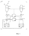
- FIG. 1 is a schematic diagram of an aircraft system 100 in accordance with an exemplary embodiment.
- the aircraft system 100 includes one or more power sources 110 and one or more fuel sources 150 housed on an aircraft 102.
- the aircraft system 100 further includes one or more controllers 190 for operating the power sources 110 and the fuel sources 150 based on predetermined instructions stored in memory and executed by a processor and/or from commands from a pilot or operators via a user interface 192 or other aircraft systems.
- the controller 190 may be, for example, a FADEC.
- the power sources 110 operate with fuel supplied by the fuel sources 150 based on commands from the controller 190.
- the power sources 110 include a main engine 120 and an auxiliary power unit (APU) 130.
- the main engine 120 may be any suitable type of engine that provides main propulsion for the aircraft 102, including turboprop engines, turboshaft engines, turbojet, and turbofan engines. As is generally known, the main engine 120 is configured to receive fuel, mix the fuel with air, ignite the mixture, and extract the energy from the resulting combustion gases.
- the APU 130 may be any suitable type of engine that provides auxiliary power for the aircraft 102, including electrical, pneumatic, and/or hydraulic power to various aircraft systems, particularly on the ground.
- the APU 130 may be, for example, a turboshaft engine that receives fuel, mixes the fuel with air, ignites the mixture, and extracts the energy from the resulting combustion gases. Additional details about the fuel utilized by the main engine 120 and the APU 130 are provided below.
- the fuel sources 150 include a main fuel tank 160, a green fuel tank 170, and a mixing apparatus 180.
- the fuel sources 150 may also be considered to include a main fuel pump 162, a main fuel sensor 164, a main fuel valve 166, a green fuel pump 172, a green fuel sensor 174, and a green fuel valve 176.
- additional pumps, valves, sensors, and the like may be provided for operating the fuel sources 150 according to the functions described below.
- the components of the fuel sources 150 will be introduced below prior to a more detailed description of operation of the fuel sources 150 within the aircraft system 100.
- the main fuel tank 160 houses primary or main fuel.
- the main fuel tank 160 may be any suitable structure for containing the primary fuel.
- the main fuel tank 160 may be composed of metal or any other suitable material to inhibit or prevent leaks.
- the main fuel tank 160 may be a number of fuel tanks dedicated to primary fuel.
- the term "primary fuel” may be used to reference traditional types of aircraft engine fuel, including kerosene based Jet A and Jet A-1 fuels and other types of fuels for commercial aviation and jet propellant JP-8 and JP-5 fuels for military jet engines.
- the main fuel pump 162 functions to remove primary fuel from the main fuel tank 160 based on commands from the controller 190.
- the main fuel sensor 164 functions to measure or derive the amount of fuel in the main fuel tank 160 and provide the amount to the controller 190 and/or the pilot via the user interface 192.
- the main fuel valve 166 is configured to direct the fuel from the main fuel tank 160 to the main fuel tank 160, the APU 170, or the mixing apparatus 180 based on commands from the controller 190, as discussed in greater detail below.
- the green fuel tank 170 houses green fuel.
- the green fuel tank 170 may be any suitable structure for containing the green fuel.
- the green fuel tank 170 may be composed of metal or any other suitable material to inhibit or prevent leaks.
- the green fuel tank 170 may be any number of fuel tanks dedicated to green fuel.
- the term "green fuel” may be used to reference various types of biofuels, including green diesel and ultra-low sulfur fuels.
- the term "green fuel” may be defined according to government regulation or industry standard.
- ASTM D7566-11 is a specification for aviation turbine fuel containing synthesized hydrocarbons.
- Such synthesized hydrocarbons may include, as examples, bio-derived synthetic components, including hydroprocessed esters and fatty acids (HEFA) from vegetable oil-containing feedstock, as well as fuel produced from coal, natural gas, or biomass using Fischer-Tropsch (FT) synthesis.
- HEFA hydroprocessed esters and fatty acids
- FT Fischer-Tropsch
- the term "ultra-low sulfur fuel,” including ultra-low sulfur diesel (ULSD) may be defined by government or industry standard.
- the green fuel pump 172 functions to remove the green fuel from the green fuel tank 170 based on commands from the controller 190.
- the green fuel sensor 174 functions to measure or derive the amount of fuel in the green fuel tank 170 and provide the amount to the controller 190 and/or the pilot via the user interface 192.
- the green fuel valve 176 is configured to direct the fuel from the green fuel tank 170 to the APU 130 or the mixing apparatus 180 based on commands from the controller 190, as discussed in greater detail below.
- the mixing apparatus 180 receives primary fuel from the main fuel tank 160 and green fuel from the green fuel tank 170.
- the mixing apparatus 180 mixes a first amount of the primary fuel and a second amount of the green fuel on-board the aircraft to provide a mixed fuel at a predetermined primary to green ratio.
- the mixing apparatus 180 may be any suitable apparatus for mixing and delivering the fuels in a predetermined ratio.
- the mixing apparatus 180 may include metering apparatus and a tank.
- the controller 190 operates the main engine 120 and the APU 130 in one or more modes. Typically, the controller 190 selects a mode for the main engine 120 and a mode for the APU 130 based on considerations discussed below.
- the controller 190 commands the fuel sources 150 to provide the main engine 120 with primary fuel from the main fuel tank 160 (e.g., via commands to the pump 162 and valve 166).
- the controller 109 commands the fuel sources 150 to provide the main engine 120 with mixed fuel from the mixing apparatus 180.
- the controller 190 commands the fuel sources 150 to provide the APU 130 with green fuel from the green fuel tank 170 (e.g., via commands to the pump 172 and valve 176).
- the controller 190 commands the fuel sources 150 to provide the APU 130 with primary fuel from the main fuel tank 160 (e.g., via commands to pump 162 and valves 166).
- the controller 190 selects the appropriate mode based on a number of considerations.
- the pilot or operator provides commands for the controller 190 via the user interface 192.
- the controller 190 selects the appropriate mode based on flight status or mode and the fuel levels within the main fuel tank 160 and the green fuel tank 170.
- the controller 190 commands the main engine 120 to operate in the first main engine mode such that the main engine 120 receives and consumes only primary fuel.
- the controller 190 commands the main engine 120 to operate in the second main engine mode such that the main engine 120 receives and consumes a mixture of primary fuel and green fuel.
- the green fuel supplements the primary fuel to supply the main engine 120. This may be particularly desirable or advantageous during unpredicted flight situations, such as an in-flight diversion, or during situations in which the amount of primary fuel consumed was greater than expected.
- the controller 190 may anticipate these situations by monitoring the amount of primary fuel remaining in the main fuel tank 160 and the updated expected usage.
- Government regulation, technical or operational specifications, or other such requirements may dictate the amount of green fuel that may be used to operate the main engine 120.
- Such requirements may be expressed as a predetermined or minimum ratio of primary fuel to green fuel.
- the predetermined or minimum ratio of primary fuel to green fuel may be 50:50. In other words, at least half of the fuel provided to the main engine 120 must be primary fuel, in one exemplary embodiment. Other ratios may be provided.
- the controller 190 monitors the amount of primary fuel remaining and the anticipated usage of primary fuel to arrive at the desired destination. If the controller 190 determines that primary fuel in the main fuel tank 160 is sufficient to arrive at the destination, the controller 190 continues to operate in the first main engine mode. However, if during flight, the controller 190 determines that the primary fuel in the main fuel tank 160 is insufficient to arrive at the destination, the controller 190 switches operation to the second main engine mode. The controller 190 may immediately transition into the second main engine mode, or the controller 190 may select an appropriate time or location to switch to the second main engine mode such that the amount of fuel in the main fuel tank 160 is sufficient to reach the desired location at the predetermined ratio of primary fuel to green fuel.
- the controller 190 may select the time or location to switch to the second main engine mode at which the remaining primary fuel is sufficient, considering the 50:50 ratio, to arrive at the desired locations.
- the controller 190 may also consider a margin of error when determining the appropriate main engine mode. As such, during the transition the second main engine mode, the controller 190 selects and commands a first amount of primary fuel and a second amount of green fuel to the mixing apparatus 180 to result in the predetermined ratio delivered to the main engine 120.
- the controller 190 may select the appropriate mode based on location and/or applicable environmental standards. For example, some countries may require lower emissions, and thus additional use of green fuels, as opposed to other countries.
- additional modes may be provided, such as modes that burn a different ratio of primary fuel and green fuel than the predetermined minimum ratio discussed above. Such different ratios may be selected based on different or additional considerations than the second main engine mode discussed above. Other considerations may include fuel efficiencies and pollution issues.
- the controller 190 may select operation in the second main engine mode to at least partially burn green fuel, which may result in less pollution than burning only primary fuel, or the controller 190 may select operation in a further APU mode in which the APU 130 burns a mixture of primary and green fuels.
- the controller 190 commands the APU 130 to operate in the first APU mode such that the APU 130 receives and consumes green fuel.
- the controller 190 commands the APU 130 to operate in the second APU mode such that the APU 130 receives and consumes primary fuel.
- the controller 190 may command the APU 130 to operate in the second APU mode, for example, when the green fuel from the green fuel tank 170 is low.
- either mode for operating the APU 130 may be selected, depending on the scenario, including the level of fuel sources, location, and emission requirements..
- controller 190 selects the appropriate main engine mode and APU engine mode to deliver and utilize the appropriate amount, combination, and type of fuel to operate in an improved manner.
- other exemplary embodiments may use green fuel in other arrangements.
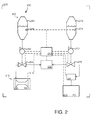
- FIG. 2 is a schematic block diagram of an aircraft system 200 according to another exemplary embodiment. Unless otherwise noted, the aircraft system 200 operates similar to the aircraft system 100 discussed above in reference to FIG. 1 .
- the aircraft system 200 includes one or more power sources 210 and one or more fuel sources 250 housed on an aircraft 202, as well as one or more controllers 290 for operating the power sources 210 and the fuel sources 250 based on predetermined instructions and/or from commands from a pilot or operators via a user interface 292.
- the power sources 210 include a fuel cell 230.
- a fuel cell 230 is an energy device that converts chemical energy from a fuel into electricity through a chemical reaction with oxygen or another oxidizing agent.
- hydrogen is the fuel, but other hydrocarbons such as natural gas and alcohols like methanol may also be used.
- electrons are drawn from the hydrogen fuel at an anode to a cathode through an external circuit, thereby producing electricity.
- Any suitable type of fuel cell 230 may be provided, including a proton exchange membrane fuel cell.
- the fuel cell 230 may provide electricity to a number of aircraft systems and/or other functions, such as tank inerting or water generation.
- the system 200 may further include an APU, as discussed above.
- the fuel sources 250 include a main fuel tank 260, a green fuel tank 270, and a mixing apparatus 280.
- the fuel sources 250 may also be considered to include a main fuel pump 262, a main fuel sensor 264, a main fuel valve 266, a green fuel pump 272, a green fuel sensor 274, and a green fuel valve 276 that operate as discussed above.
- additional pumps, valves, sensors, and the like may be provided for operating the fuel sources 250 according to the functions described below.
- a green fuel processor 278 may also be provided.
- the green fuel processor 278 receives green fuel and functions to generate hydrogen from the green fuel.
- the fuel processor 278 may generate hydrogen, for example, from any suitable fuel reforming technique, including steam reforming and autothermal reforming.
- the controller 290 operates the main engine 220 in one or more modes.
- the controller 290 operates the fuel cell 230 in a single mode.
- the controller 290 commands the green fuel tank 270 (e.g., via the green fuel pump 272 and the green fuel valve 276) to deliver green fuel to the green fuel processor 278.
- the green fuel processor 278 provides hydrogen fuel to the fuel cell 230 for the generation of electricity.
- the controller 290 selects a mode for the main engine 220 based on considerations discussed below.
- the controller 290 commands the fuel sources 250 to provide the main engine 220 with primary fuel from the main fuel tank 260 (e.g., via commands to the pump 262 and valve 266).
- the controller 290 commands the fuel sources 250 to provide the main engine 220 with mixed fuel from the mixing apparatus 280.
- the controller 290 commands the main engine 220 to operate in the first main engine mode such that the main engine 220 receives and consumes only primary fuel.
- the controller 290 commands the main engine 220 to operate in the second main engine mode such that the main engine 220 receives and consumes a mixture of primary fuel and green fuel, as discussed above. Accordingly, the controller 290 selects the appropriate main engine mode to deliver and utilize the appropriate amount, combination, and type of fuel to operate in an improved manner.
- the main fuel tank e.g., main fuel tank 160, 260
- the green fuel tank e.g., green fuel tank 170, 270
- the main fuel tank and the green fuel tank are configured as dedicated and separate tanks, as depicted in FIGS. 1 and 2 .
- the main fuel tanks 160, 260 discussed above contain only (e.g., 100%) primary fuel
- the green fuel tanks 170, 270 discussed above contain only (e.g., 100%) green fuel.
- each fuel tank may be more easily serviced and/or additional total fuel may be provided as compared to conventional fuel systems that only have primary fuel. Additional exemplary arrangements are discussed below.
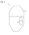
- FIG. 3 is a schematic view of a fuel tank assembly 300 according to another exemplary embodiment.
- the fuel tank assembly 300 includes a main fuel tank 360 and a green fuel tank 370 that function as discussed above.
- the green fuel tank 370 is arranged within the main fuel tank 360.
- the main fuel tank 360 contains the green fuel tank 370
- tanks 360, 370 are arranged such that the fuels remain separate.
- any leaks in the green fuel tank 370 may be contained by the main fuel tank 360 without hazard. Additionally, this arrangement results in a same total volume of fuel and fuel tanks as a conventional arrangement with only main fuel tanks.
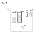
- FIG. 4 is a schematic representation of a user interface 400 of an aircraft system according to an exemplary embodiment.
- the user interface 400 may be coupled to the controller (e.g., controllers 190. 290) of the systems 100, 200 discussed above.
- the controller e.g., controllers 190. 290
- any suitable control functionality may be provided for the systems 100, 200 with the associated appropriate interaction enabled by the user interface 400.
- the systems 100, 200 may be automatic such that no user input is necessary. In such embodiments, the user interface 400 may be omitted.
- the user interface 400 may include a display device, such as a suitably configured liquid crystal display (LCD), plasma, cathode ray tube (CRT), or head-up display, graphical elements.
- LCD liquid crystal display
- CRT cathode ray tube
- the user interface 400 enables the user to enter data and/or control the various aspects of the systems 100, 200 ( FIGS. 1 and 2 ).
- the user interface 400 may be formed by interactive graphical elements rendered on a touch screen of the display device.
- Other user input devices may include a keyboard or keypad, a voice recognition system, a cursor control device, a joystick or knob, or the like.
- the user interface 400 may include visual depictions of a level of fuel 410 in the main fuel tank (e.g., fuel tank 160, 260) and a level of fuel 420 in the green fuel tank (e.g., fuel tank 170, 270).
- a level of fuel 410 in the main fuel tank e.g., fuel tank 160, 260
- a level of fuel 420 in the green fuel tank e.g., fuel tank 170, 270.
- the user interface 400 further includes one or more switches 430, 440 that enable selection of one or more of the modes discussed above. As shown, switch 430 enables selection between a first main engine mode in which the main engine receives only primary fuel and a second main engine mode in which the main engine receives a mixture of primary and green fuels.
- switch 440 is provided to enable selection between a first APU mode in which the APU receives only green fuel and a second APU mode in which the APU receives only primary fuel.
- the user interface 400 includes one or more warning lights 450.
- the warning light 450 may inform the operator that one or more of the fuel tanks is getting low and/or that the mode should be switched. Other selections and/or information corresponding to the functions discussed above may be provided.
- exemplary embodiments discussed above may include a separate green (or bio-) fuel tank with green fuel for the APU and or fuel cell, while also making the green fuel available for the main engines to use.
- green fuel may include less sulfur than primary fuel. This allows the APU and or fuel cell to have the advantages of reduced emissions and no sulfur and alleviates the issue that the unused green fuel from a flight as dead weight that was otherwise carried around just for the APU and fuel cell.
- the green tank may be drained into the normal main engine fuel tanks.
- current certification requirements would require that the concentration of the main fuel tanks be maintained below 50% green fuel, which may be managed by a controller or other type of metering device.
- aircraft are typically required to maintain certain reserves of fuel for emergencies like diversion to new airports.
- the green fuel in the green fuel tank would not need to be mixed into the main tanks to be included in the reserve calculation.
- draining of the green fuel tank would only need to be done in extreme situations when the fuel reserves were down to very low levels, e.g., approaching the 50% green fuel concentration after mixing.
- This would allow many flights worth of green fuel to be carried with no penalty for the green fuel tank or green fuel weight. This would reduce the need for green fuel at all airports and the extra servicing of the green fuel tank for each flight.
Landscapes
- Engineering & Computer Science (AREA)
- Aviation & Aerospace Engineering (AREA)
- Chemical & Material Sciences (AREA)
- Combustion & Propulsion (AREA)
- Mechanical Engineering (AREA)
- General Engineering & Computer Science (AREA)
- Life Sciences & Earth Sciences (AREA)
- Manufacturing & Machinery (AREA)
- Sustainable Development (AREA)
- Sustainable Energy (AREA)
- Chemical Kinetics & Catalysis (AREA)
- Electrochemistry (AREA)
- General Chemical & Material Sciences (AREA)
- Output Control And Ontrol Of Special Type Engine (AREA)
Applications Claiming Priority (1)
| Application Number | Priority Date | Filing Date | Title |
|---|---|---|---|
| US14/223,428 US20150266589A1 (en) | 2014-03-24 | 2014-03-24 | Aircraft systems and methods with green fuel tanks |
Publications (2)
| Publication Number | Publication Date |
|---|---|
| EP2923948A1 true EP2923948A1 (de) | 2015-09-30 |
| EP2923948B1 EP2923948B1 (de) | 2020-05-06 |
Family
ID=52684012
Family Applications (1)
| Application Number | Title | Priority Date | Filing Date |
|---|---|---|---|
| EP15158115.4A Active EP2923948B1 (de) | 2014-03-24 | 2015-03-06 | Flugzeugsysteme und verfahren mit tanks für grünen kraftstoff |
Country Status (2)
| Country | Link |
|---|---|
| US (1) | US20150266589A1 (de) |
| EP (1) | EP2923948B1 (de) |
Cited By (7)
| Publication number | Priority date | Publication date | Assignee | Title |
|---|---|---|---|---|
| GB2614947A (en) * | 2021-12-21 | 2023-07-26 | Rolls Royce Plc | Aircraft propulsion |
| US11815031B2 (en) | 2021-12-21 | 2023-11-14 | Rolls-Royce Plc | Fuelling schedule |
| US12085029B2 (en) | 2021-12-21 | 2024-09-10 | Rolls-Royce Plc | Propulsion system control |
| GB2630394A (en) * | 2023-05-26 | 2024-11-27 | Airbus Operations Ltd | Aircraft access cover |
| GB2630393A (en) * | 2023-05-26 | 2024-11-27 | Airbus Operations Ltd | Aircraft fuel storage structure |
| US12351337B2 (en) | 2021-11-19 | 2025-07-08 | General Electric Company | Sub-coolers for refueling onboard cryogenic fuel tanks and methods for operating the same |
| US12595884B2 (en) | 2022-10-06 | 2026-04-07 | General Electric Company | Methods, apparatus, systems, and articles of manufacture to produce cryo-compressed hydrogen |
Families Citing this family (11)
| Publication number | Priority date | Publication date | Assignee | Title |
|---|---|---|---|---|
| FR3015574B1 (fr) * | 2013-12-20 | 2019-05-03 | Safran Helicopter Engines | Procede de commande automatique du regime de fonctionnement d'un turbomoteur d'un helicoptere, dispositif de commande correspondant et helicoptere equipe d'un tel dispositif |
| EP3184611B1 (de) * | 2015-12-21 | 2020-06-03 | Neste Corporation | Verfahren zur herstellung einer flugkraftstoffzusammensetzung |
| CN110092002B (zh) * | 2018-01-30 | 2024-06-18 | 哈米尔顿森德斯特兰德公司 | 飞机的油箱催化惰化设备 |
| CN109625297A (zh) * | 2018-12-11 | 2019-04-16 | 石家庄飞机工业有限责任公司 | 一种用于小型通用飞机的燃油系统 |
| DE102021104092A1 (de) | 2021-02-22 | 2022-08-25 | Deutsches Zentrum für Luft- und Raumfahrt e.V. | Verfahren zum Betreiben eines Flugzeugs in Abhängigkeit von einem Betriebsmodus |
| US20230024316A1 (en) * | 2021-07-19 | 2023-01-26 | Embraer S.A. | Environmentally Friendly Aircraft |
| US11891178B2 (en) * | 2022-04-28 | 2024-02-06 | Jetzero, Inc. | Blended wing body aircraft with a combustion engine and method of use |
| US20230193834A1 (en) * | 2021-12-21 | 2023-06-22 | Rolls-Royce Plc | Method of controlling an aircraft propulsion system with a variable inlet guide vane, and propulsion system with a variable inlet guide vane scheduling manager |
| GB2617309A (en) | 2021-12-21 | 2023-10-11 | Rolls Royce Plc | Aircraft fuel management |
| US12253033B2 (en) | 2022-10-04 | 2025-03-18 | General Electric Company | Hydrogen fuel leak detection system for a vehicle |
| GB202219409D0 (en) * | 2022-12-21 | 2023-02-01 | Rolls Royce Plc | Fuel management system |
Citations (6)
| Publication number | Priority date | Publication date | Assignee | Title |
|---|---|---|---|---|
| US4761948A (en) * | 1987-04-09 | 1988-08-09 | Solar Turbines Incorporated | Wide range gaseous fuel combustion system for gas turbine engines |
| WO2009040112A2 (en) * | 2007-09-25 | 2009-04-02 | Eads Deutschland Gmbh | Method for operating a gas turbine engine, power supplying device for conducting such method and aircraft using such method |
| US7818969B1 (en) * | 2009-12-18 | 2010-10-26 | Energyield, Llc | Enhanced efficiency turbine |
| US20110101166A1 (en) * | 2009-11-05 | 2011-05-05 | Airbus Operations Gmbh | Control unit and method for controlling the supply of a vehicle with multiple fuels |
| US20130192246A1 (en) * | 2010-09-30 | 2013-08-01 | General Electric Company | Dual fuel aircraft engine control system and method for operating same |
| EP2677138A2 (de) * | 2012-06-22 | 2013-12-25 | Rolls-Royce plc | Kraftstoffsystem |
Family Cites Families (7)
| Publication number | Priority date | Publication date | Assignee | Title |
|---|---|---|---|---|
| US5469830A (en) * | 1995-02-24 | 1995-11-28 | The Cessna Aircraft Company | Fuel blending system method and apparatus |
| US20030163994A1 (en) * | 2001-12-21 | 2003-09-04 | Kabushiki Kaisha Meidensha | Generator set for vegetable oil and method of operating the same |
| US8006677B2 (en) * | 2006-02-02 | 2011-08-30 | Immixt, LLC | Fuel control system and associated method |
| WO2011041085A2 (en) * | 2009-09-11 | 2011-04-07 | Washington State University Research Foundation | Catalyst materials and methods for reforming hydrocarbon fuels |
| EP2621808A1 (de) * | 2010-09-30 | 2013-08-07 | General Electric Company | Brennstoffzellensystem für ein flugzeug |
| US8355819B2 (en) * | 2010-10-05 | 2013-01-15 | General Electric Company | Method, apparatus and system for igniting wide range of turbine fuels |
| WO2014092185A1 (ja) * | 2012-12-13 | 2014-06-19 | 川崎重工業株式会社 | マルチ燃料対応のガスタービン燃焼器 |
-
2014
- 2014-03-24 US US14/223,428 patent/US20150266589A1/en not_active Abandoned
-
2015
- 2015-03-06 EP EP15158115.4A patent/EP2923948B1/de active Active
Patent Citations (6)
| Publication number | Priority date | Publication date | Assignee | Title |
|---|---|---|---|---|
| US4761948A (en) * | 1987-04-09 | 1988-08-09 | Solar Turbines Incorporated | Wide range gaseous fuel combustion system for gas turbine engines |
| WO2009040112A2 (en) * | 2007-09-25 | 2009-04-02 | Eads Deutschland Gmbh | Method for operating a gas turbine engine, power supplying device for conducting such method and aircraft using such method |
| US20110101166A1 (en) * | 2009-11-05 | 2011-05-05 | Airbus Operations Gmbh | Control unit and method for controlling the supply of a vehicle with multiple fuels |
| US7818969B1 (en) * | 2009-12-18 | 2010-10-26 | Energyield, Llc | Enhanced efficiency turbine |
| US20130192246A1 (en) * | 2010-09-30 | 2013-08-01 | General Electric Company | Dual fuel aircraft engine control system and method for operating same |
| EP2677138A2 (de) * | 2012-06-22 | 2013-12-25 | Rolls-Royce plc | Kraftstoffsystem |
Cited By (13)
| Publication number | Priority date | Publication date | Assignee | Title |
|---|---|---|---|---|
| US12351337B2 (en) | 2021-11-19 | 2025-07-08 | General Electric Company | Sub-coolers for refueling onboard cryogenic fuel tanks and methods for operating the same |
| US12331692B2 (en) | 2021-12-21 | 2025-06-17 | Rolls-Royce Plc | Flight profile |
| US11815031B2 (en) | 2021-12-21 | 2023-11-14 | Rolls-Royce Plc | Fuelling schedule |
| US12085029B2 (en) | 2021-12-21 | 2024-09-10 | Rolls-Royce Plc | Propulsion system control |
| GB2614947B (en) * | 2021-12-21 | 2024-09-25 | Rolls Royce Plc | Aircraft propulsion |
| US12240614B2 (en) | 2021-12-21 | 2025-03-04 | Rolls-Royce Plc | Aircraft propulsion |
| US12297781B2 (en) | 2021-12-21 | 2025-05-13 | Rolls-Royce Plc | Operating an aircraft |
| GB2614947A (en) * | 2021-12-21 | 2023-07-26 | Rolls Royce Plc | Aircraft propulsion |
| US11780597B2 (en) | 2021-12-21 | 2023-10-10 | Rolls-Royce Plc | Aircraft propulsion |
| US12503983B2 (en) | 2021-12-21 | 2025-12-23 | Rolls-Royce Plc | Propulsion system control |
| US12595884B2 (en) | 2022-10-06 | 2026-04-07 | General Electric Company | Methods, apparatus, systems, and articles of manufacture to produce cryo-compressed hydrogen |
| GB2630394A (en) * | 2023-05-26 | 2024-11-27 | Airbus Operations Ltd | Aircraft access cover |
| GB2630393A (en) * | 2023-05-26 | 2024-11-27 | Airbus Operations Ltd | Aircraft fuel storage structure |
Also Published As
| Publication number | Publication date |
|---|---|
| US20150266589A1 (en) | 2015-09-24 |
| EP2923948B1 (de) | 2020-05-06 |
Similar Documents
| Publication | Publication Date | Title |
|---|---|---|
| EP2923948B1 (de) | Flugzeugsysteme und verfahren mit tanks für grünen kraftstoff | |
| US7966830B2 (en) | Fuel cell/combustor systems and methods for aircraft and other applications | |
| Baharozu et al. | Future aircraft concept in terms of energy efficiency and environmental factors | |
| US8430360B2 (en) | Control unit and method for controlling the supply of a vehicle with multiple fuels | |
| RU2643614C2 (ru) | Способ снабжения дополнительной мощностью вспомогательной силовой установкой и соответствующая конструкция | |
| US10913543B2 (en) | Power system for more electric aircraft | |
| US9656762B2 (en) | System for temperature and actuation control and method of controlling fluid temperatures in an aircraft | |
| Daggett et al. | Fuel cell apu | |
| EP4086444A1 (de) | Integrierte brennstoffzelle und motorbrennkammeranordnung | |
| WO2023000048A1 (en) | Environmentally friendly aircraft | |
| US20110133545A1 (en) | Aircraft electrical power system architecture using auxiliary power unit during approach and taxi | |
| CN103456976A (zh) | 用于提供电功率的系统和方法 | |
| CN109018387A (zh) | 一种采用高压除水的飞机油箱惰化装置及其方法 | |
| CN116428055A (zh) | 用燃料电池减少排放的系统和方法 | |
| CN116892447A (zh) | 具有燃料电池组件的燃气涡轮发动机 | |
| CN116398293A (zh) | 用于向燃气涡轮发动机的燃烧室提供输出产物的系统和方法 | |
| US12255363B2 (en) | Integrated fuel cell and combustor assembly | |
| US12372039B2 (en) | Blended fuel dispensing system with adaptive fuel storage parameters | |
| Stoia et al. | A highly efficient solid oxide fuel cell power system for an all-electric commuter airplane flight demonstrator | |
| Chowdhury et al. | Next-gen aviation: Who will rule the skies—Hydrogen or electric?—A review | |
| CN116398292B (zh) | 用于向燃气涡轮发动机的燃烧室提供输出产物的系统和方法 | |
| Daggett | Hybrid SOFC-powered mid-range commercial aircraft concept | |
| Aigner et al. | Consideration of technology scalability in the design of electric propulsion system architectures | |
| US12116141B2 (en) | Aircraft emergency power unit with battery powered subsystem | |
| KR20170067770A (ko) | 터보 엔진의 연소실을 위한 점화시스템 |
Legal Events
| Date | Code | Title | Description |
|---|---|---|---|
| PUAI | Public reference made under article 153(3) epc to a published international application that has entered the european phase |
Free format text: ORIGINAL CODE: 0009012 |
|
| 17P | Request for examination filed |
Effective date: 20150306 |
|
| AK | Designated contracting states |
Kind code of ref document: A1 Designated state(s): AL AT BE BG CH CY CZ DE DK EE ES FI FR GB GR HR HU IE IS IT LI LT LU LV MC MK MT NL NO PL PT RO RS SE SI SK SM TR |
|
| AX | Request for extension of the european patent |
Extension state: BA ME |
|
| RAP1 | Party data changed (applicant data changed or rights of an application transferred) |
Owner name: HONEYWELL INTERNATIONAL INC. |
|
| STAA | Information on the status of an ep patent application or granted ep patent |
Free format text: STATUS: EXAMINATION IS IN PROGRESS |
|
| 17Q | First examination report despatched |
Effective date: 20180615 |
|
| GRAP | Despatch of communication of intention to grant a patent |
Free format text: ORIGINAL CODE: EPIDOSNIGR1 |
|
| STAA | Information on the status of an ep patent application or granted ep patent |
Free format text: STATUS: GRANT OF PATENT IS INTENDED |
|
| INTG | Intention to grant announced |
Effective date: 20191218 |
|
| RIN1 | Information on inventor provided before grant (corrected) |
Inventor name: ACHARYA, MUKUND Inventor name: SCAINI, MARIO Inventor name: HAGH, BIJAN F. Inventor name: MAK, AUDIE Inventor name: BLUMER, ERIC |
|
| GRAS | Grant fee paid |
Free format text: ORIGINAL CODE: EPIDOSNIGR3 |
|
| GRAA | (expected) grant |
Free format text: ORIGINAL CODE: 0009210 |
|
| STAA | Information on the status of an ep patent application or granted ep patent |
Free format text: STATUS: THE PATENT HAS BEEN GRANTED |
|
| AK | Designated contracting states |
Kind code of ref document: B1 Designated state(s): AL AT BE BG CH CY CZ DE DK EE ES FI FR GB GR HR HU IE IS IT LI LT LU LV MC MK MT NL NO PL PT RO RS SE SI SK SM TR |
|
| REG | Reference to a national code |
Ref country code: GB Ref legal event code: FG4D |
|
| REG | Reference to a national code |
Ref country code: CH Ref legal event code: EP Ref country code: AT Ref legal event code: REF Ref document number: 1266366 Country of ref document: AT Kind code of ref document: T Effective date: 20200515 |
|
| REG | Reference to a national code |
Ref country code: IE Ref legal event code: FG4D |
|
| REG | Reference to a national code |
Ref country code: DE Ref legal event code: R096 Ref document number: 602015051984 Country of ref document: DE |
|
| REG | Reference to a national code |
Ref country code: LT Ref legal event code: MG4D |
|
| REG | Reference to a national code |
Ref country code: NL Ref legal event code: MP Effective date: 20200506 |
|
| PG25 | Lapsed in a contracting state [announced via postgrant information from national office to epo] |
Ref country code: LT Free format text: LAPSE BECAUSE OF FAILURE TO SUBMIT A TRANSLATION OF THE DESCRIPTION OR TO PAY THE FEE WITHIN THE PRESCRIBED TIME-LIMIT Effective date: 20200506 Ref country code: FI Free format text: LAPSE BECAUSE OF FAILURE TO SUBMIT A TRANSLATION OF THE DESCRIPTION OR TO PAY THE FEE WITHIN THE PRESCRIBED TIME-LIMIT Effective date: 20200506 Ref country code: GR Free format text: LAPSE BECAUSE OF FAILURE TO SUBMIT A TRANSLATION OF THE DESCRIPTION OR TO PAY THE FEE WITHIN THE PRESCRIBED TIME-LIMIT Effective date: 20200807 Ref country code: NO Free format text: LAPSE BECAUSE OF FAILURE TO SUBMIT A TRANSLATION OF THE DESCRIPTION OR TO PAY THE FEE WITHIN THE PRESCRIBED TIME-LIMIT Effective date: 20200806 Ref country code: SE Free format text: LAPSE BECAUSE OF FAILURE TO SUBMIT A TRANSLATION OF THE DESCRIPTION OR TO PAY THE FEE WITHIN THE PRESCRIBED TIME-LIMIT Effective date: 20200506 Ref country code: IS Free format text: LAPSE BECAUSE OF FAILURE TO SUBMIT A TRANSLATION OF THE DESCRIPTION OR TO PAY THE FEE WITHIN THE PRESCRIBED TIME-LIMIT Effective date: 20200906 Ref country code: PT Free format text: LAPSE BECAUSE OF FAILURE TO SUBMIT A TRANSLATION OF THE DESCRIPTION OR TO PAY THE FEE WITHIN THE PRESCRIBED TIME-LIMIT Effective date: 20200907 |
|
| PG25 | Lapsed in a contracting state [announced via postgrant information from national office to epo] |
Ref country code: HR Free format text: LAPSE BECAUSE OF FAILURE TO SUBMIT A TRANSLATION OF THE DESCRIPTION OR TO PAY THE FEE WITHIN THE PRESCRIBED TIME-LIMIT Effective date: 20200506 Ref country code: RS Free format text: LAPSE BECAUSE OF FAILURE TO SUBMIT A TRANSLATION OF THE DESCRIPTION OR TO PAY THE FEE WITHIN THE PRESCRIBED TIME-LIMIT Effective date: 20200506 Ref country code: LV Free format text: LAPSE BECAUSE OF FAILURE TO SUBMIT A TRANSLATION OF THE DESCRIPTION OR TO PAY THE FEE WITHIN THE PRESCRIBED TIME-LIMIT Effective date: 20200506 Ref country code: BG Free format text: LAPSE BECAUSE OF FAILURE TO SUBMIT A TRANSLATION OF THE DESCRIPTION OR TO PAY THE FEE WITHIN THE PRESCRIBED TIME-LIMIT Effective date: 20200806 |
|
| REG | Reference to a national code |
Ref country code: AT Ref legal event code: MK05 Ref document number: 1266366 Country of ref document: AT Kind code of ref document: T Effective date: 20200506 |
|
| PG25 | Lapsed in a contracting state [announced via postgrant information from national office to epo] |
Ref country code: NL Free format text: LAPSE BECAUSE OF FAILURE TO SUBMIT A TRANSLATION OF THE DESCRIPTION OR TO PAY THE FEE WITHIN THE PRESCRIBED TIME-LIMIT Effective date: 20200506 Ref country code: AL Free format text: LAPSE BECAUSE OF FAILURE TO SUBMIT A TRANSLATION OF THE DESCRIPTION OR TO PAY THE FEE WITHIN THE PRESCRIBED TIME-LIMIT Effective date: 20200506 |
|
| PG25 | Lapsed in a contracting state [announced via postgrant information from national office to epo] |
Ref country code: IT Free format text: LAPSE BECAUSE OF FAILURE TO SUBMIT A TRANSLATION OF THE DESCRIPTION OR TO PAY THE FEE WITHIN THE PRESCRIBED TIME-LIMIT Effective date: 20200506 Ref country code: EE Free format text: LAPSE BECAUSE OF FAILURE TO SUBMIT A TRANSLATION OF THE DESCRIPTION OR TO PAY THE FEE WITHIN THE PRESCRIBED TIME-LIMIT Effective date: 20200506 Ref country code: DK Free format text: LAPSE BECAUSE OF FAILURE TO SUBMIT A TRANSLATION OF THE DESCRIPTION OR TO PAY THE FEE WITHIN THE PRESCRIBED TIME-LIMIT Effective date: 20200506 Ref country code: AT Free format text: LAPSE BECAUSE OF FAILURE TO SUBMIT A TRANSLATION OF THE DESCRIPTION OR TO PAY THE FEE WITHIN THE PRESCRIBED TIME-LIMIT Effective date: 20200506 Ref country code: SM Free format text: LAPSE BECAUSE OF FAILURE TO SUBMIT A TRANSLATION OF THE DESCRIPTION OR TO PAY THE FEE WITHIN THE PRESCRIBED TIME-LIMIT Effective date: 20200506 Ref country code: ES Free format text: LAPSE BECAUSE OF FAILURE TO SUBMIT A TRANSLATION OF THE DESCRIPTION OR TO PAY THE FEE WITHIN THE PRESCRIBED TIME-LIMIT Effective date: 20200506 Ref country code: CZ Free format text: LAPSE BECAUSE OF FAILURE TO SUBMIT A TRANSLATION OF THE DESCRIPTION OR TO PAY THE FEE WITHIN THE PRESCRIBED TIME-LIMIT Effective date: 20200506 Ref country code: RO Free format text: LAPSE BECAUSE OF FAILURE TO SUBMIT A TRANSLATION OF THE DESCRIPTION OR TO PAY THE FEE WITHIN THE PRESCRIBED TIME-LIMIT Effective date: 20200506 |
|
| REG | Reference to a national code |
Ref country code: DE Ref legal event code: R097 Ref document number: 602015051984 Country of ref document: DE |
|
| PG25 | Lapsed in a contracting state [announced via postgrant information from national office to epo] |
Ref country code: SK Free format text: LAPSE BECAUSE OF FAILURE TO SUBMIT A TRANSLATION OF THE DESCRIPTION OR TO PAY THE FEE WITHIN THE PRESCRIBED TIME-LIMIT Effective date: 20200506 Ref country code: PL Free format text: LAPSE BECAUSE OF FAILURE TO SUBMIT A TRANSLATION OF THE DESCRIPTION OR TO PAY THE FEE WITHIN THE PRESCRIBED TIME-LIMIT Effective date: 20200506 |
|
| PLBE | No opposition filed within time limit |
Free format text: ORIGINAL CODE: 0009261 |
|
| STAA | Information on the status of an ep patent application or granted ep patent |
Free format text: STATUS: NO OPPOSITION FILED WITHIN TIME LIMIT |
|
| 26N | No opposition filed |
Effective date: 20210209 |
|
| PG25 | Lapsed in a contracting state [announced via postgrant information from national office to epo] |
Ref country code: SI Free format text: LAPSE BECAUSE OF FAILURE TO SUBMIT A TRANSLATION OF THE DESCRIPTION OR TO PAY THE FEE WITHIN THE PRESCRIBED TIME-LIMIT Effective date: 20200506 |
|
| PG25 | Lapsed in a contracting state [announced via postgrant information from national office to epo] |
Ref country code: MC Free format text: LAPSE BECAUSE OF FAILURE TO SUBMIT A TRANSLATION OF THE DESCRIPTION OR TO PAY THE FEE WITHIN THE PRESCRIBED TIME-LIMIT Effective date: 20200506 |
|
| REG | Reference to a national code |
Ref country code: CH Ref legal event code: PL |
|
| GBPC | Gb: european patent ceased through non-payment of renewal fee |
Effective date: 20210306 |
|
| REG | Reference to a national code |
Ref country code: BE Ref legal event code: MM Effective date: 20210331 |
|
| PG25 | Lapsed in a contracting state [announced via postgrant information from national office to epo] |
Ref country code: CH Free format text: LAPSE BECAUSE OF NON-PAYMENT OF DUE FEES Effective date: 20210331 Ref country code: LU Free format text: LAPSE BECAUSE OF NON-PAYMENT OF DUE FEES Effective date: 20210306 Ref country code: LI Free format text: LAPSE BECAUSE OF NON-PAYMENT OF DUE FEES Effective date: 20210331 Ref country code: IE Free format text: LAPSE BECAUSE OF NON-PAYMENT OF DUE FEES Effective date: 20210306 Ref country code: GB Free format text: LAPSE BECAUSE OF NON-PAYMENT OF DUE FEES Effective date: 20210306 Ref country code: FR Free format text: LAPSE BECAUSE OF NON-PAYMENT OF DUE FEES Effective date: 20210331 |
|
| PG25 | Lapsed in a contracting state [announced via postgrant information from national office to epo] |
Ref country code: BE Free format text: LAPSE BECAUSE OF NON-PAYMENT OF DUE FEES Effective date: 20210331 |
|
| PG25 | Lapsed in a contracting state [announced via postgrant information from national office to epo] |
Ref country code: HU Free format text: LAPSE BECAUSE OF FAILURE TO SUBMIT A TRANSLATION OF THE DESCRIPTION OR TO PAY THE FEE WITHIN THE PRESCRIBED TIME-LIMIT; INVALID AB INITIO Effective date: 20150306 |
|
| PG25 | Lapsed in a contracting state [announced via postgrant information from national office to epo] |
Ref country code: CY Free format text: LAPSE BECAUSE OF FAILURE TO SUBMIT A TRANSLATION OF THE DESCRIPTION OR TO PAY THE FEE WITHIN THE PRESCRIBED TIME-LIMIT Effective date: 20200506 |
|
| P01 | Opt-out of the competence of the unified patent court (upc) registered |
Effective date: 20230525 |
|
| PG25 | Lapsed in a contracting state [announced via postgrant information from national office to epo] |
Ref country code: MK Free format text: LAPSE BECAUSE OF FAILURE TO SUBMIT A TRANSLATION OF THE DESCRIPTION OR TO PAY THE FEE WITHIN THE PRESCRIBED TIME-LIMIT Effective date: 20200506 |
|
| PG25 | Lapsed in a contracting state [announced via postgrant information from national office to epo] |
Ref country code: TR Free format text: LAPSE BECAUSE OF FAILURE TO SUBMIT A TRANSLATION OF THE DESCRIPTION OR TO PAY THE FEE WITHIN THE PRESCRIBED TIME-LIMIT Effective date: 20200506 |
|
| PG25 | Lapsed in a contracting state [announced via postgrant information from national office to epo] |
Ref country code: MT Free format text: LAPSE BECAUSE OF FAILURE TO SUBMIT A TRANSLATION OF THE DESCRIPTION OR TO PAY THE FEE WITHIN THE PRESCRIBED TIME-LIMIT Effective date: 20200506 |
|
| PGFP | Annual fee paid to national office [announced via postgrant information from national office to epo] |
Ref country code: DE Payment date: 20260320 Year of fee payment: 12 |