EP2923944A1 - Ornithopter - Google Patents
Ornithopter Download PDFInfo
- Publication number
- EP2923944A1 EP2923944A1 EP14754397.9A EP14754397A EP2923944A1 EP 2923944 A1 EP2923944 A1 EP 2923944A1 EP 14754397 A EP14754397 A EP 14754397A EP 2923944 A1 EP2923944 A1 EP 2923944A1
- Authority
- EP
- European Patent Office
- Prior art keywords
- spar
- angle
- motion
- ornithopter
- wing
- Prior art date
- Legal status (The legal status is an assumption and is not a legal conclusion. Google has not performed a legal analysis and makes no representation as to the accuracy of the status listed.)
- Granted
Links
Images


Classifications
-
- B—PERFORMING OPERATIONS; TRANSPORTING
- B64—AIRCRAFT; AVIATION; COSMONAUTICS
- B64C—AEROPLANES; HELICOPTERS
- B64C33/00—Ornithopters
- B64C33/02—Wings; Actuating mechanisms therefor
-
- A—HUMAN NECESSITIES
- A63—SPORTS; GAMES; AMUSEMENTS
- A63H—TOYS, e.g. TOPS, DOLLS, HOOPS OR BUILDING BLOCKS
- A63H27/00—Toy aircraft; Other flying toys
- A63H27/008—Propelled by flapping of wings
-
- B—PERFORMING OPERATIONS; TRANSPORTING
- B64—AIRCRAFT; AVIATION; COSMONAUTICS
- B64C—AEROPLANES; HELICOPTERS
- B64C3/00—Wings
- B64C3/18—Spars; Ribs; Stringers
- B64C3/187—Ribs
-
- B—PERFORMING OPERATIONS; TRANSPORTING
- B64—AIRCRAFT; AVIATION; COSMONAUTICS
- B64U—UNMANNED AERIAL VEHICLES [UAV]; EQUIPMENT THEREFOR
- B64U10/00—Type of UAV
- B64U10/40—Ornithopters
Definitions
- the present invention relates to an ornithopter.
- a small unmanned air vehicle is developed.
- Such a UAV at the present moment is mainly a fixed wing type or a rotary wing type.
- development of "flapping type” which imitates birds or insects is initiated.
- the flapping type UAV has characteristics of both the fixed wing type and the rotary wing type, and is expected from the viewpoint of quietness, low visibility, mimetic characteristics etc.
- Such a flapping type UAV is hereinafter referred to as an "ornithopter".
- Patent Literature 1 Japan Patent No. 4,675,346 discloses an example of the ornithopter.
- This ornithopter includes a main body, and a pair of wings attached to the main body.
- One of the pair of wings is attached to a left side portion of the main body, and the other of the pair of wings is attached to a right side portion of the main body.
- Each wing is a single piece wing.
- the ornithopter floats and travels in the air by a flapping motion and a torsional motion of the pair of the single piece wings.
- Patent Literature 1 Japan Patent No. 4,675,346
- An object of the present invention is to provide an ornithopter having high mimetic characteristics, and which can reduce weight, simplify a mechanism and suppress thrust loss and increase of drag.
- an ornithopter in one aspect of the present invention, includes a main wing mounted on a fuselage.
- the main wing includes a main spar extending outwardly from the fuselage, and a rib extending rearwardly from the main spar.
- the rib has an S-shaped camber.
- an ornithopter having high mimetic characteristics and which can reduce weight, simplify a mechanism and suppress thrust loss and increase of drag is realized.
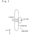
- Fig. 1 is the plan view of the ornithopter 1 according to the present embodiment.
- a coordinate system will be defined.
- "+ X-direction” corresponds to a traveling direction (direction of flight) of the ornithopter 1, and means a forward direction.
- "- X-direction” means a rearward direction.
- "Y-direction” corresponds to a sideward direction of the ornithopter 1, and is perpendicular to the X-direction.
- Z-direction is a direction perpendicular to both the X-direction and the Y-direction.
- "+ Z-direction” means an upward direction
- "- Z-direction” means a downward direction.
- XY-plane corresponds to a horizontal plane
- + Z-direction corresponds to a vertically upward direction.
- the ornithopter 1 includes a fuselage 2, a tail wing 3, and a pair of main wings 10.
- the tail wing 3 is mounted on a rear portion of the fuselage 2.
- the pair of main wings 10 is mounted on a left side surface of the fuselage 2 and a right side surface of the fuselage 2, respectively.
- a flapping motion of the ornithopter 1 is realized by automatically moving the pair of main wings 10 under control of the control system 100.
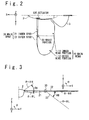
- Fig. 2 is the schematic diagram for indicating the configuration of the main wing 10 of the ornithopter 1.
- the main wing 10 is not a single piece wing, includes a mimicked wrist portion, and is bendable. More specifically, the main wing 10 has an inner wing portion 11 and an outer wing portion 12.
- the inner wing portion 11 is a portion of an inner side (a side closer to the fuselage 2) of the main wing 10, and is connected to a shoulder portion of the fuselage 2.
- the outer wing portion 12 is a portion of an outer side (a side farther from the fuselage 2) of the main wing 10, and is connected to an outer end of the inner wing portion 11.
- the main wing 10 includes a main spar 20 as a frame.
- the main spar 20 is disposed to extend outwardly (toward a direction away from the fuselage 2) from the shoulder portion of the fuselage 2.
- the main spar 20 has an inner spar 21 and an outer spar 22.
- the inner spar 21 is a portion, which is provided in the inner wing portion 11, of the main spar 20, and is disposed to extend outwardly from the shoulder portion of the fuselage 2.
- the outer spar 22 is a portion, which is provided in the outer wing portion 12, of the main spar 20, and is disposed to extend further outwardly than the inner spar 21.
- the main wing 10 further includes a wrist portion 30 disposed between the inner spar 21 and the outer spar 22. That is, the inner spar 21 and the outer spar 22 are connected to each other via the wrist portion 30.
- the wrist portion 30 is a movable portion, and the main spar 20 is bendable at this wrist portion 30. A configuration example of the wrist portion 30 will be explained later.
- a fuselage-side end portion (a root portion) of the inner spar 21 is connected to an actuator 120 provided on the shoulder portion of the fuselage 2.
- This actuator 120 moves the inner spar 21 in an upward direction or a downward direction in a rotational and reciprocating manner around the shoulder portion of the fuselage 2 as a center of rotation or around a straight line parallel to the X-axis as a rotation axis.
- the inner spar 21 rotates around the shoulder portion of the fuselage 2, which is the center of rotation, or around the straight line parallel to the X-axis, which is the rotation axis. Its rotational angle is hereinafter referred to as a "flapping angle ⁇ ". As the inner spar 21 rotates in the "+ Z-direction" (the upward direction), the flapping angle ⁇ increases. On the other hand, as the inner spar 21 rotates in the "- Z-direction" (the downward direction), the flapping angle ⁇ decreases.
- a variation range RA of the flapping angle ⁇ is predetermined, and an upper limit and a lower limit of the predetermined variation range RA are ⁇ H and ⁇ L, respectively. That is, the flapping angle ⁇ varies within the predetermined variation range RA defined by the upper limit angle ⁇ H and the lower limit angle ⁇ L.
- the flapping angle ⁇ is the upper limit angle ⁇ H
- the inner spar 21 is located at the top position (+ Z-direction side).
- the flapping angle ⁇ is the lower limit angle ⁇ L
- the inner spar 21 is located at the bottom position (- Z-direction side).
- actuator 120 that varies the flapping angle ⁇ of the inner spar 21.
- the actuator 120 moves the inner spar 21 in the upward direction or in the downward direction in the rotational and reciprocating manner, varies the flapping angle ⁇ within the predetermined variation range RA.
- a motion of rotating the inner spar 21 in the downward direction that is, a motion of decreasing the flapping angle ⁇ toward the lower limit angle ⁇ L corresponds to the "lowering motion”.
- a motion of rotating the inner spar 21 in the upward direction that is, a motion of increasing the flapping angle ⁇ toward the upper limit angle ⁇ H corresponds to the "raising motion".
- the outer spar 22 connected to the inner spar 21 via the wrist portion 30 relatively moves with respect to the inner spar 21.
- the relative angle between the inner spar 21 and the outer spar 22 is hereinafter referred to as a "bending angle ⁇ ".
- an extending direction of the inner spar 21 corresponds to an S-direction.
- the S-direction is perpendicular to the X-direction.
- a T-direction is a direction perpendicular to both the X-direction and the S-direction. + T-direction means an upward direction, and - T-direction means a downward direction.
- the outer spar 22 rotates around the wrist portion 30 as a center of rotation, or around a straight line parallel to the X-axis as the rotation axis. Its rotational angle is above mentioned "bending angle ⁇ ". As the outer spar 22 rotates in the + T-direction (the upward direction), the bending angle ⁇ increases. On the other hand, as the outer spar 22 rotates in the - T-direction (the downward direction), the bending angle ⁇ decreases.
- a variation range RB of the bending angle ⁇ is predetermined, and an upper limit and a lower limit of the predetermined variation range RB are ⁇ H and ⁇ L, respectively. That is, the bending angle ⁇ varies within the predetermined variation range RB defined by the upper limit angle ⁇ H and the lower limit angle ⁇ L.
- the outer spar 22 is located at the top position (+ T-direction side).
- the inner spar 21 and the outer spar 22 are forming a straight line. That is, an extending direction of the outer spar 22 coincides with the S-direction.
- embodiments are not limited to above mentioned example.
- the outer spar 22 is located at the bottom position (-T-direction side).
- an actuator is not provided with respect to the outer spar 22. That is, in the wrist portion 30, the actuator for directly and mechanically moving the outer spar 22 is not provided. As will be explained later in detail, the outer spar 22 follows the lowering motion and the raising motion of the inner spar 21, and is moved only in a "passive" manner.
- the wrist portion 30 is configured such that the bending angle ⁇ of the outer spar 22 varies within the predetermined variable range RB.
- Fig. 4A and Fig. 4B schematically indicate a configuration example of such a wrist portion 30.
- Fig. 4A is an SX-cross-sectional view taken along the line A-A' in Fig. 4B
- Fig. 4B is an ST-cross-sectional view taken along the line B-B' in Fig. 4A .
- a connector 31 connected to an end portion of the inner spar 21 is provided on an end portion of the outer spar 22 .
- a shaft 32 which can move integrally with the outer spar 22 is provided on an end portion of the outer spar 22 is provided on an end portion of the outer spar 22 .
- the shaft 32 is fitted in a hole formed in the connector 31.
- the outer spar 22 can rotate around the shaft 32. That is, the bending angle ⁇ of the outer spar 22 becomes variable.
- the upper limit angle ⁇ H and the lower limit angle ⁇ L of the bending angle ⁇ can be set appropriately by adjusting a shape of the connector as shown in Fig. 4B .
- the variation range RB of the bending angle ⁇ is appropriately set by a mechanical limiter.
- a position where an upper surface of the outer spar 22 is contact with a lower surface of an upper portion of the connector 31 corresponds to the upper limit angle ⁇ H
- a position where a lower surface of the outer spar 22 is contact with an end surface of a lower portion of the connector 31 corresponds to the lower limit angle ⁇ L.
- an angle sensor 130 for measuring the bending angle ⁇ is provided in the wrist portion 30, in the wrist portion 30, an angle sensor 130 for measuring the bending angle ⁇ .
- a gear 33 is provided on one end of the shaft 32, and is configured to rotate with the rotation of the outer spar 22.
- the angle sensor 130 is disposed on the connector 31 so as to be adjacent to the gear 33, and measures the bending angle ⁇ of the outer spar 22 based on the rotation of the gear 33.
- the bending angle ⁇ measured by the angle sensor 130 is used to control a motion of the inner spar 21.
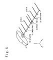
- a rib which is another frame of the main wing 10, will be explained.
- a plurality of the ribs 25 is mounted on the main spar 20, a plurality of the ribs 25 is mounted.
- Each rib 25 is provided so as to extend rearwardly (- X-direction) from the main spar 20.
- Fig. 6 indicates a configuration of one rib 25.
- a front side portion of the rib 25 (+ X-direction side) is a rib front portion 25F.
- a rear side portion of the rib 25 (- X-direction side) is a rib rear portion 25R.
- a hole 26 is formed in the rib front portion 25F, and the main spar 20 passes through the hole 26. That is, the rib 25 is disposed rotatably about the main spar 20.
- the rib 25 has an S-shaped camber (an inverted camber).
- the rib rear portion 25R is curved upward. Referring to Fig. 7 , a function of this S-shaped camber wing will be explained.
- the rib 25 having the S-shaped camber is automatically tilted (twisted) from the X-direction as shown in Fig. 7 .
- This tilt angle (twist amount) is determined based on a flight speed of the ornithopter 1 and a lowering speed of the main wing 10 at the position of the ornithopter 1, and the tilt angle becomes larger as the lowering speed becomes higher.
- a wing plane L of the main wing 10 (for simplicity, the wing plane is represented linearly) is automatically inclined at some angle from the X-direction. Then, since the wing plane L is inclined from the X-direction, a thrust in the + X-direction (traveling direction) is generated as shown in Fig. 7 . That is, the wing plane L is automatically inclined such that the wing plane L becomes stable against the wind vane direction, and consequently the thrust is generated.
- an actuator is not provided for the rib 25.
- an actuator for directly and mechanically moving the rib 25 is not provided.
- the rib 25 has the S-shaped camber, and is automatically tilted (twisted) from the X-direction during the lowering motion of the main wing 10.
- the ornithopter 1 has a control system 100 for controlling a flapping motion of the main wing 10.
- Fig. 8 is the block diagram for indicating a function and a configuration of the control system 100.
- the control system 100 includes a control unit 110, the actuator 120, the angle sensor 130, and an angle sensor 140.
- the actuator 120 is a mechanical mechanism for moving the inner spar 21.
- the actuator 120 rotates the inner spar 21 in the upward direction or the downward direction, and thereby the raising motion or the lowering motion is realized.
- the angle sensor 130 is provided in the wrist portion 30, and measures the bending angle ⁇ of the outer spar 22. Then, the angle sensor 130 transmits bending angle data DB indicating the measured bending angle ⁇ to the control unit 110 in a real-time manner.
- the angle sensor 140 is provided with the actuator 120, and measures the flapping angle ⁇ of the inner spar 21. Then, the angle sensor 140 transmits flapping angle data DA indicating the measured flapping angle ⁇ to the control unit 110 in a real-time manner. Note that the angle sensor 140 is not necessarily required.
- the control unit 110 is a computer that is mounted inside the fuselage 2.
- the control unit 110 controls the raising motion and the lowering motion of the inner spar 21 by controlling the actuator 120. More specifically, the control unit 110 receives the flapping angle data DA and the bending angle data DB, and monitors the flapping angle ⁇ and the bending angle ⁇ in a real-time manner. Then, the control unit 110 controls the actuator 120 and moves the inner spar 21 in response to at least the bending angle ⁇ .
- a controlled object by the control unit 110 is, for example, a timing of the raising motion and the lowering motion.
- Fig. 9 is the timing chart for indicating the example of the control.
- transition of the flapping angle ⁇ of the inner spar 21 and transition of the bending angle ⁇ of the outer spar 22, respectively are indicated.
- states S1 to S5 correspond to the lowering motion
- states S6 to S10 correspond to the raising motion.
- the lowering motion (states S1 to S5) and the raising motion (states S6 to S10), respectively will be explained in detail.
- Fig. 10 is the conceptual diagram for explaining the lowering motion. Referring to Fig. 9 and Fig. 10 , the lowering motion will be explained.
- the state S1 is a state in which both the inner spar 21 and the outer spar 22 are at the top position.
- the flapping angle ⁇ is the upper limit angle ⁇ H
- the bending angle ⁇ is the upper limit angle ⁇ H.
- the lowering motion is started.
- the control unit 110 controls the actuator 120 to initiate the lowering motion of the inner spar 21.
- the state S2 is a state in which the inner spar 21 is being lowered by the actuator 120.
- the flapping angle ⁇ is an intermediate angle ⁇ M ( ⁇ H> ⁇ M> ⁇ L).
- the outer spar 22 is passively moved in the downward direction by following the lowering motion of the inner spar 21, while the bending angle ⁇ is remained in the upper limit angle ⁇ H.
- the rib 25 having the S-shaped camber is automatically tilted (twisted) from the X-direction. That is, the wing plane L of the wing 10 is automatically inclined at some angle from the X-direction. Thereby, the thrust in the + X-direction (traveling direction) is generated.
- the tilt angle tilt angle (twist amount) is determined based on the flight speed of the ornithopter 1 and the lowering speed of the main wing 10 at the position of the ornithopter 1, and the tilt angle becomes larger as the lowering speed becomes higher. Therefore, the tilt angle as well as the resultant thrust is progressively increasing toward the wing tip (as farther from the fuselage 2).
- the state S3 is a state in which the inner spar 21 is at the bottom position.
- the flapping angle ⁇ is the lower limit angle ⁇ L.
- the motion of the inner spar 21 is stopped in this moment, while the outer spar 22, which was following the inner spar 21, continues to move by the inertia. That is, the outer spar 22 naturally moves by the momentum of the lowering motion of the inner spar 21 even if the actuator is not provided with the outer spar.
- the state S4 is a state in which only the outer spar 22 moves, while the inner spar 21 is at the bottom position.
- the bending angle ⁇ is an intermediate angle ⁇ M ( ⁇ H> ⁇ M> ⁇ L). Note that, in this moment, the actuator 120 fixes the inner spar 21, and keeps the flapping angle ⁇ at the lower limit angle ⁇ L.
- the state S5 is a state in which both the inner spar 21 and the outer spar 22 are at the bottom position.
- the flapping angle ⁇ is the lower limit angle ⁇ L
- the bending angle ⁇ is the lower limit angle ⁇ L.
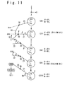
- Fig. 11 is the conceptual diagram for explaining the raising motion. Referring to Fig. 9 and Fig. 11 , the raising motion will be explained.
- the state S6 is the same as the above mentioned state S5. In this state S6, the fixation of the inner spar 21 is released, and the raising motion is initiated. Specifically, the control unit 110 controls the actuator 120 to start the raising motion of the inner spar 21.
- the state S7 is a state in which the inner spar 21 is being raised by the actuator 120.
- the flapping angle ⁇ is an intermediate angle ⁇ M ( ⁇ H> ⁇ M> ⁇ L).
- the outer spar 22 is passively moved in the upward direction by following the raising motion of the inner spar 21, while the bending angle ⁇ is remained in the lower limit angle ⁇ L.
- the state S8 is a state in which the inner spar 21 is at the top position.
- the flapping angle ⁇ is the upper limit angle ⁇ H.
- the motion of the inner spar 21 is stopped in this moment, while the outer spar 22, which was following the inner spar 21, continues to move by the inertia. That is, the outer spar 22 naturally moves by the momentum of the raising motion of the inner spar 21 even if the actuator is not provided with the outer spar.
- the state S9 is a state in which only the outer spar 22 moves, while the inner spar 21 is at the top position.
- the bending angle ⁇ is an intermediate angle ⁇ M ( ⁇ H> ⁇ M> ⁇ L). Note that, in this moment, the actuator 120 fixes the inner spar 21, and keeps the flapping angle ⁇ at the upper limit angle ⁇ H.
- the state S10 is a state in which both the inner spar 21 and the outer spar 22 are at the top position.
- the flapping angle ⁇ is the upper limit angle ⁇ H
- the bending angle ⁇ is the upper limit angle ⁇ H.
- the control unit 110 which monitors the flapping angle ⁇ and the bending angle ⁇ in the real-time manner using the angle sensors 130 and 140, detects this state S10, above mentioned lowering control (see state S1) is initiated. That is, when the state in which the bending angle ⁇ becomes the upper limit angle ⁇ H is detected after the raising motion of the inner spar 21, the control unit 110 controls the actuator 120 to initiate the lowering motion of the inner spar 21.
- the control unit 110 controls the actuator 120 to only release the fixation of the inner spar 21.
- the flapping motion of the ornithopter 1 according to the present embodiment is realized.
- the main wing 10 of ornithopter 1 includes the mimicked wrist portion 30 configured to be bendable. Therefore, mimetic characteristics are improved and the thrust loss and the increase of the drag are suppressed as compared to the case in which the single piece wing is used.
- an actuator for directly and mechanically moving the outer spar 22 is provided. Then, in addition to the inner spar 21, the outer spar 22 is forcibly moved using the actuator. Furthermore, an actuator is also provided for the rib 25, and by forcibly inclining the rib 25, the wing plane L is tilted from the X-direction. Motion states (motion timing, motion frequency, motion speed) of the inner spar 21, the outer spar 22 and the rib 25 using the actuators are appropriately set, respectively.
- the actuator for directly and mechanically moving the outer spar 22 is not provided in the wrist portion 30.
- the outer spar 22 only passively moves by following the lowering motion and the raising motion of the inner spar 21.
- the outer spar 22, which follows the inner spar 21 naturally moves by the momentum of the raising motion or the lowering motion of the inner spar 21 without the actuator.
- the actuator is not provided with respect to the rib 25. That is, the actuator for directly and mechanically moving the rib 25 is not provided.
- the rib 25 has the S-shaped camber form, and is automatically tilted from the X-direction during the lowering motion of the main wing 10.
- the angle sensor 130 for measuring the bending angle ⁇ of the outer spar 22 is provided in the wrist portion 30. Then, the control unit 110 controls the actuator 120 to move the inner spar 21 in response to the measured bending angle ⁇ by the angle sensor 130.
- the lowering motion is initiated after the outer spar 22 reaches the top position (after the bending angle ⁇ becomes the upper limit angle ⁇ H).
- the raising motion is initiated after the outer spar 22 reaches the bottom position (after the bending angle ⁇ becomes the lower limit angle ⁇ L). That is, it is possible to realize the optimum flapping motion from the viewpoint of the thrust, the drag, and the mimetic characteristics. Since the bending angle ⁇ itself is monitored using the angle sensor 130, the optimum flapping motion is always realized regardless of the environment such as the flight speed. In this sense, the present embodiment can be said to have a high adaptability to the environment.
- the outer spar 22 passively moves by following the lowering motion and the raising motion of the inner spar 21.
- a cushioning member 40 may be provided in the wrist portion 30.
- the cushioning member 40 serves to mitigate momentum of relative motion of the outer spar 22 with respect to the inner spar 21.
- the cushioning member 40 is a spring connecting between the outer spar 22 and a support member. With such a cushioning member 40, it is possible to suppress a sudden movement of the outer spar 22. As a result, the mimetic characteristics of the ornithopter 1 are further improved.
- a reference value of the bending angle ⁇ which is served as the trigger may not necessarily be the upper limit angle ⁇ H or the lower limit angle ⁇ L.
- the reference value of the bending angle ⁇ which is served as the trigger may be appropriately set based on a motion mode of the ornithopter 1 or an intended purpose.
Landscapes
- Engineering & Computer Science (AREA)
- Aviation & Aerospace Engineering (AREA)
- Mechanical Engineering (AREA)
- Remote Sensing (AREA)
- Toys (AREA)
Abstract
Description
- The present invention relates to an ornithopter.
- A small unmanned air vehicle (UAV) is developed. Such a UAV at the present moment is mainly a fixed wing type or a rotary wing type. However, as a future UAV form, development of "flapping type" which imitates birds or insects is initiated. The flapping type UAV has characteristics of both the fixed wing type and the rotary wing type, and is expected from the viewpoint of quietness, low visibility, mimetic characteristics etc. Such a flapping type UAV is hereinafter referred to as an "ornithopter".
- Patent Literature 1 (Japan Patent No.
4,675,346 - Patent Literature 1:
Japan Patent No. 4,675,346 - In the ornithopter disclosed in
Patent Literature 1, a torsional motion of a wing is actively controlled by an ultrasonic motor. In the case of adopting the active control, an extra actuator and an extra wiring are required. Therefore, problems such as weight increase and complication of a mechanism occur. Then, the weight increase and the complication of the mechanism cause problems such as increase of thrust loss and drag. In addition, since the way of actively twisting the wing is different from a mechanism in a natural bird, the mimetic characteristics are deteriorated. - An object of the present invention is to provide an ornithopter having high mimetic characteristics, and which can reduce weight, simplify a mechanism and suppress thrust loss and increase of drag.
- In one aspect of the present invention, an ornithopter is provided. The ornithopter includes a main wing mounted on a fuselage. The main wing includes a main spar extending outwardly from the fuselage, and a rib extending rearwardly from the main spar. The rib has an S-shaped camber.
- According to the present invention, an ornithopter having high mimetic characteristics and which can reduce weight, simplify a mechanism and suppress thrust loss and increase of drag is realized.
-
-
Fig. 1 is a plan view of the ornithopter according to some embodiments; -
Fig. 2 is a schematic diagram for indicating a configuration of a main wing of the ornithopter according to some embodiments; -
Fig. 3 is a conceptual diagram for indicating a movable range of an inner spar and an outer spar of the ornithopter according to some embodiments; -
Fig. 4A is a schematic diagram for indicating a configuration of a wrist portion of the ornithopter according to some embodiments; -
Fig. 4B is a schematic diagram for indicating the configuration of the wrist portion of the ornithopter according to some embodiments; -
Fig. 5 is a schematic diagram for indicating a configuration of a main spar and ribs of the ornithopter according to some embodiments; -
Fig. 6 is a schematic diagram for indicating the configuration of the rib of the ornithopter according to some embodiments; -
Fig. 7 is a schematic diagram for indicating a function of the rib of the ornithopter according to some embodiments; -
Fig. 8 is a block diagram for indicating a function and a configuration of a control system of the ornithopter according to some embodiments; -
Fig. 9 is a timing chart for indicating a lowering motion and a raising motion of the main wing of the ornithopter according to some embodiments; -
Fig. 10 is a conceptual diagram for explaining the lowering motion of the main wing of the ornithopter according to some embodiments; -
Fig. 11 is a conceptual diagram for explaining the raising motion of the main wing of the ornithopter according to some embodiments; and -
Fig. 12 is a schematic diagram for indicating an alternative example of some embodiments. - Referring to the drawings, an ornithopter according to some embodiments will be explained.
-
Fig. 1 is the plan view of theornithopter 1 according to the present embodiment. Firstly, a coordinate system will be defined. "+ X-direction" corresponds to a traveling direction (direction of flight) of theornithopter 1, and means a forward direction. On the other hand, "- X-direction" means a rearward direction. "Y-direction" corresponds to a sideward direction of theornithopter 1, and is perpendicular to the X-direction. "Z-direction" is a direction perpendicular to both the X-direction and the Y-direction. "+ Z-direction" means an upward direction, and "- Z-direction" means a downward direction. Typically, XY-plane corresponds to a horizontal plane, and + Z-direction corresponds to a vertically upward direction. - As shown in
Fig. 1 , theornithopter 1 includes afuselage 2, atail wing 3, and a pair ofmain wings 10. Thetail wing 3 is mounted on a rear portion of thefuselage 2. The pair ofmain wings 10 is mounted on a left side surface of thefuselage 2 and a right side surface of thefuselage 2, respectively. As described later in more detail, a flapping motion of theornithopter 1 is realized by automatically moving the pair ofmain wings 10 under control of thecontrol system 100. -
Fig. 2 is the schematic diagram for indicating the configuration of themain wing 10 of theornithopter 1. In this embodiment, themain wing 10 is not a single piece wing, includes a mimicked wrist portion, and is bendable. More specifically, themain wing 10 has aninner wing portion 11 and an outer wing portion 12. Theinner wing portion 11 is a portion of an inner side (a side closer to the fuselage 2) of themain wing 10, and is connected to a shoulder portion of thefuselage 2. On the other hand, the outer wing portion 12 is a portion of an outer side (a side farther from the fuselage 2) of themain wing 10, and is connected to an outer end of theinner wing portion 11. - The
main wing 10 includes amain spar 20 as a frame. Themain spar 20 is disposed to extend outwardly (toward a direction away from the fuselage 2) from the shoulder portion of thefuselage 2. More specifically, themain spar 20 has aninner spar 21 and anouter spar 22. Theinner spar 21 is a portion, which is provided in theinner wing portion 11, of themain spar 20, and is disposed to extend outwardly from the shoulder portion of thefuselage 2. On the other hand, theouter spar 22 is a portion, which is provided in the outer wing portion 12, of themain spar 20, and is disposed to extend further outwardly than theinner spar 21. - The
main wing 10 further includes awrist portion 30 disposed between theinner spar 21 and theouter spar 22. That is, theinner spar 21 and theouter spar 22 are connected to each other via thewrist portion 30. Thewrist portion 30 is a movable portion, and themain spar 20 is bendable at thiswrist portion 30. A configuration example of thewrist portion 30 will be explained later. - A fuselage-side end portion (a root portion) of the
inner spar 21 is connected to anactuator 120 provided on the shoulder portion of thefuselage 2. Thisactuator 120 moves theinner spar 21 in an upward direction or a downward direction in a rotational and reciprocating manner around the shoulder portion of thefuselage 2 as a center of rotation or around a straight line parallel to the X-axis as a rotation axis. Thereby, a "lowering motion" and a "raising motion" of the inner spar 21 (i.e. the main wing 10) are realized. - Next, referring to
Fig. 3 , a movable range of theinner spar 21 and theouter spar 22 will be explained. - The
inner spar 21 rotates around the shoulder portion of thefuselage 2, which is the center of rotation, or around the straight line parallel to the X-axis, which is the rotation axis. Its rotational angle is hereinafter referred to as a "flapping angle θ". As theinner spar 21 rotates in the "+ Z-direction" (the upward direction), the flapping angle θ increases. On the other hand, as theinner spar 21 rotates in the "- Z-direction" (the downward direction), the flapping angle θ decreases. - A variation range RA of the flapping angle θ is predetermined, and an upper limit and a lower limit of the predetermined variation range RA are θH and θL, respectively. That is, the flapping angle θ varies within the predetermined variation range RA defined by the upper limit angle θH and the lower limit angle θL. When the flapping angle θ is the upper limit angle θH, the
inner spar 21 is located at the top position (+ Z-direction side). On the other hand, when the flapping angle θ is the lower limit angle θL, theinner spar 21 is located at the bottom position (- Z-direction side). - It is above mentioned
actuator 120 that varies the flapping angle θ of theinner spar 21. Theactuator 120 moves theinner spar 21 in the upward direction or in the downward direction in the rotational and reciprocating manner, varies the flapping angle θ within the predetermined variation range RA. A motion of rotating theinner spar 21 in the downward direction, that is, a motion of decreasing the flapping angle θ toward the lower limit angle θL corresponds to the "lowering motion". On the other hand, a motion of rotating theinner spar 21 in the upward direction, that is, a motion of increasing the flapping angle θ toward the upper limit angle θH corresponds to the "raising motion". - The
outer spar 22 connected to theinner spar 21 via thewrist portion 30 relatively moves with respect to theinner spar 21. The relative angle between theinner spar 21 and theouter spar 22 is hereinafter referred to as a "bending angle ϕ". - Here, in order to facilitate to the explanation of the bending angle ϕ, a relative coordinate system in which the
inner spar 21 is used as a reference is defined. As shown inFig. 3 , an extending direction of theinner spar 21 corresponds to an S-direction. The S-direction is perpendicular to the X-direction. Also, a T-direction is a direction perpendicular to both the X-direction and the S-direction. + T-direction means an upward direction, and - T-direction means a downward direction. - The
outer spar 22 rotates around thewrist portion 30 as a center of rotation, or around a straight line parallel to the X-axis as the rotation axis. Its rotational angle is above mentioned "bending angle ϕ". As theouter spar 22 rotates in the + T-direction (the upward direction), the bending angle ϕ increases. On the other hand, as theouter spar 22 rotates in the - T-direction (the downward direction), the bending angle ϕ decreases. - A variation range RB of the bending angle ϕ is predetermined, and an upper limit and a lower limit of the predetermined variation range RB are ϕH and ϕL, respectively. That is, the bending angle ϕ varies within the predetermined variation range RB defined by the upper limit angle ϕH and the lower limit angle ϕL. When the bending angle ϕ is the upper limit angle ϕH, the
outer spar 22 is located at the top position (+ T-direction side). Typically, when the bending angle ϕ is the upper limit angle ϕH, theinner spar 21 and theouter spar 22 are forming a straight line. That is, an extending direction of theouter spar 22 coincides with the S-direction. However, embodiments are not limited to above mentioned example. On the other hand, when the bending angle ϕ is the lower limit angle ϕL, theouter spar 22 is located at the bottom position (-T-direction side). - In the present embodiment, unlike the case of the
inner spar 21 described above, an actuator is not provided with respect to theouter spar 22. That is, in thewrist portion 30, the actuator for directly and mechanically moving theouter spar 22 is not provided. As will be explained later in detail, theouter spar 22 follows the lowering motion and the raising motion of theinner spar 21, and is moved only in a "passive" manner. - The
wrist portion 30 is configured such that the bending angle ϕ of theouter spar 22 varies within the predetermined variable range RB.Fig. 4A and Fig. 4B schematically indicate a configuration example of such awrist portion 30.Fig. 4A is an SX-cross-sectional view taken along the line A-A' inFig. 4B, and Fig. 4B is an ST-cross-sectional view taken along the line B-B' inFig. 4A . - As shown in
Fig. 4A and Fig. 4B , in thewrist portion 30, aconnector 31 connected to an end portion of theinner spar 21 is provided. Also, on an end portion of theouter spar 22, ashaft 32 which can move integrally with theouter spar 22 is provided. Theshaft 32 is fitted in a hole formed in theconnector 31. Thereby, theouter spar 22 can rotate around theshaft 32. That is, the bending angle ϕ of theouter spar 22 becomes variable. The upper limit angle ϕH and the lower limit angle ϕL of the bending angle ϕ can be set appropriately by adjusting a shape of the connector as shown inFig. 4B . In other words, the variation range RB of the bending angle ϕ is appropriately set by a mechanical limiter. For example, a position where an upper surface of theouter spar 22 is contact with a lower surface of an upper portion of theconnector 31 corresponds to the upper limit angle ϕH, and a position where a lower surface of theouter spar 22 is contact with an end surface of a lower portion of theconnector 31 corresponds to the lower limit angle ϕL. - Further, in the
wrist portion 30, anangle sensor 130 for measuring the bending angle ϕ is provided. In the example shown inFig. 4A and Fig. 4B , agear 33 is provided on one end of theshaft 32, and is configured to rotate with the rotation of theouter spar 22. Theangle sensor 130 is disposed on theconnector 31 so as to be adjacent to thegear 33, and measures the bending angle ϕ of theouter spar 22 based on the rotation of thegear 33. As explained later in detail, according to the present embodiment, the bending angle ϕ measured by theangle sensor 130 is used to control a motion of theinner spar 21. - Next, referring to
Figs. 5 to 7 , a rib, which is another frame of themain wing 10, will be explained. As shown inFig. 5 , on themain spar 20, a plurality of theribs 25 is mounted. Eachrib 25 is provided so as to extend rearwardly (- X-direction) from themain spar 20. -
Fig. 6 indicates a configuration of onerib 25. A front side portion of the rib 25 (+ X-direction side) is arib front portion 25F. On the other hand, a rear side portion of the rib 25 (- X-direction side) is a ribrear portion 25R. As shown inFig. 6 , ahole 26 is formed in therib front portion 25F, and themain spar 20 passes through thehole 26. That is, therib 25 is disposed rotatably about themain spar 20. - In addition, in the present embodiment, the
rib 25 has an S-shaped camber (an inverted camber). The ribrear portion 25R is curved upward. Referring toFig. 7 , a function of this S-shaped camber wing will be explained. During the lowering motion of themain wing 10, therib 25 having the S-shaped camber is automatically tilted (twisted) from the X-direction as shown inFig. 7 . This tilt angle (twist amount) is determined based on a flight speed of theornithopter 1 and a lowering speed of themain wing 10 at the position of theornithopter 1, and the tilt angle becomes larger as the lowering speed becomes higher. That is, during the lowering motion of themain wing 10, a wing plane L of the main wing 10 (for simplicity, the wing plane is represented linearly) is automatically inclined at some angle from the X-direction. Then, since the wing plane L is inclined from the X-direction, a thrust in the + X-direction (traveling direction) is generated as shown inFig. 7 . That is, the wing plane L is automatically inclined such that the wing plane L becomes stable against the wind vane direction, and consequently the thrust is generated. - Note that, in the present embodiment, an actuator is not provided for the
rib 25. In other words, an actuator for directly and mechanically moving therib 25 is not provided. As described above, therib 25 has the S-shaped camber, and is automatically tilted (twisted) from the X-direction during the lowering motion of themain wing 10. - The
ornithopter 1 according to the present embodiment has acontrol system 100 for controlling a flapping motion of themain wing 10.Fig. 8 is the block diagram for indicating a function and a configuration of thecontrol system 100. Thecontrol system 100 includes acontrol unit 110, theactuator 120, theangle sensor 130, and anangle sensor 140. - As described above, the
actuator 120 is a mechanical mechanism for moving theinner spar 21. Theactuator 120 rotates theinner spar 21 in the upward direction or the downward direction, and thereby the raising motion or the lowering motion is realized. - As described above, the
angle sensor 130 is provided in thewrist portion 30, and measures the bending angle ϕ of theouter spar 22. Then, theangle sensor 130 transmits bending angle data DB indicating the measured bending angle ϕ to thecontrol unit 110 in a real-time manner. - The
angle sensor 140 is provided with theactuator 120, and measures the flapping angle θ of theinner spar 21. Then, theangle sensor 140 transmits flapping angle data DA indicating the measured flapping angle θ to thecontrol unit 110 in a real-time manner. Note that theangle sensor 140 is not necessarily required. - The
control unit 110 is a computer that is mounted inside thefuselage 2. Thecontrol unit 110 controls the raising motion and the lowering motion of theinner spar 21 by controlling theactuator 120. More specifically, thecontrol unit 110 receives the flapping angle data DA and the bending angle data DB, and monitors the flapping angle θ and the bending angle ϕ in a real-time manner. Then, thecontrol unit 110 controls theactuator 120 and moves theinner spar 21 in response to at least the bending angle ϕ. A controlled object by thecontrol unit 110 is, for example, a timing of the raising motion and the lowering motion. - Next, an example of control for the lowering motion and the raising motion will be explained.
Fig. 9 is the timing chart for indicating the example of the control. InFig. 9 , transition of the flapping angle θ of theinner spar 21 and transition of the bending angle ϕ of theouter spar 22, respectively are indicated. In addition, states S1 to S5 correspond to the lowering motion, and states S6 to S10 correspond to the raising motion. In the following, the lowering motion (states S1 to S5) and the raising motion (states S6 to S10), respectively will be explained in detail. -
Fig. 10 is the conceptual diagram for explaining the lowering motion. Referring toFig. 9 andFig. 10 , the lowering motion will be explained. - The state S1 is a state in which both the
inner spar 21 and theouter spar 22 are at the top position. In this moment, the flapping angle θ is the upper limit angle θH, and the bending angle ϕ is the upper limit angle ϕH. In this state S1, the lowering motion is started. Specifically, thecontrol unit 110 controls theactuator 120 to initiate the lowering motion of theinner spar 21. - The state S2 is a state in which the
inner spar 21 is being lowered by theactuator 120. In this moment, the flapping angle θ is an intermediate angle θM (θH> θM> θL). Theouter spar 22 is passively moved in the downward direction by following the lowering motion of theinner spar 21, while the bending angle ϕ is remained in the upper limit angle ϕH. - Further, as explained with reference to
Fig. 7 , therib 25 having the S-shaped camber is automatically tilted (twisted) from the X-direction. That is, the wing plane L of thewing 10 is automatically inclined at some angle from the X-direction. Thereby, the thrust in the + X-direction (traveling direction) is generated. Note that the tilt angle (twist amount) is determined based on the flight speed of theornithopter 1 and the lowering speed of themain wing 10 at the position of theornithopter 1, and the tilt angle becomes larger as the lowering speed becomes higher. Therefore, the tilt angle as well as the resultant thrust is progressively increasing toward the wing tip (as farther from the fuselage 2). - The state S3 is a state in which the
inner spar 21 is at the bottom position. In this moment, the flapping angle θ is the lower limit angle θL. The motion of theinner spar 21 is stopped in this moment, while theouter spar 22, which was following theinner spar 21, continues to move by the inertia. That is, theouter spar 22 naturally moves by the momentum of the lowering motion of theinner spar 21 even if the actuator is not provided with the outer spar. - The state S4 is a state in which only the
outer spar 22 moves, while theinner spar 21 is at the bottom position. In this moment, the bending angle ϕ is an intermediate angle ϕM (ϕH> ϕM> ϕL). Note that, in this moment, theactuator 120 fixes theinner spar 21, and keeps the flapping angle θ at the lower limit angle θL. - The state S5 is a state in which both the
inner spar 21 and theouter spar 22 are at the bottom position. In this moment, the flapping angle θ is the lower limit angle θL, and the bending angle ϕ is the lower limit angle ϕL. When thecontrol unit 110, which monitors the flapping angle θ and the bending angle ϕ in the real-time manner using theangle sensors inner spar 21, thecontrol unit 110 controls theactuator 120 to initiate the raising motion of theinner spar 21. -
Fig. 11 is the conceptual diagram for explaining the raising motion. Referring toFig. 9 andFig. 11 , the raising motion will be explained. - The state S6 is the same as the above mentioned state S5. In this state S6, the fixation of the
inner spar 21 is released, and the raising motion is initiated. Specifically, thecontrol unit 110 controls theactuator 120 to start the raising motion of theinner spar 21. - The state S7 is a state in which the
inner spar 21 is being raised by theactuator 120. In this moment, the flapping angle θ is an intermediate angle θM (θH> θM> θL). Theouter spar 22 is passively moved in the upward direction by following the raising motion of theinner spar 21, while the bending angle ϕ is remained in the lower limit angle ϕL. - The state S8 is a state in which the
inner spar 21 is at the top position. In this moment, the flapping angle θ is the upper limit angle θH. The motion of theinner spar 21 is stopped in this moment, while theouter spar 22, which was following theinner spar 21, continues to move by the inertia. That is, theouter spar 22 naturally moves by the momentum of the raising motion of theinner spar 21 even if the actuator is not provided with the outer spar. - The state S9 is a state in which only the
outer spar 22 moves, while theinner spar 21 is at the top position. In this moment, the bending angle ϕ is an intermediate angle ϕM (ϕH> ϕM> ϕL). Note that, in this moment, theactuator 120 fixes theinner spar 21, and keeps the flapping angle θ at the upper limit angle θH. - The state S10 is a state in which both the
inner spar 21 and theouter spar 22 are at the top position. In this moment, the flapping angle θ is the upper limit angle θH, and the bending angle ϕ is the upper limit angle ϕH. When thecontrol unit 110, which monitors the flapping angle θ and the bending angle ϕ in the real-time manner using theangle sensors inner spar 21, thecontrol unit 110 controls theactuator 120 to initiate the lowering motion of theinner spar 21. - Note that in the raising motion, there exists a possibility that the
main wing 10 is automatically raised by aerodynamic force. In such a case, it is not necessary to actively move theinner spar 21 using theactuator 120. In this case, in the state S6, thecontrol unit 110 controls theactuator 120 to only release the fixation of theinner spar 21. - By repeating the lowering motion and the raising motion described above, the flapping motion of the
ornithopter 1 according to the present embodiment is realized. - According to the present embodiment, the
main wing 10 ofornithopter 1 includes the mimickedwrist portion 30 configured to be bendable. Therefore, mimetic characteristics are improved and the thrust loss and the increase of the drag are suppressed as compared to the case in which the single piece wing is used. - Furthermore, according to the present embodiment, the following effects can be obtained. To illustrate the effects, firstly, following comparative example will be considered.
- In the comparative example, in the
wrist portion 30, an actuator (motor, link mechanism etc.) for directly and mechanically moving theouter spar 22 is provided. Then, in addition to theinner spar 21, theouter spar 22 is forcibly moved using the actuator. Furthermore, an actuator is also provided for therib 25, and by forcibly inclining therib 25, the wing plane L is tilted from the X-direction. Motion states (motion timing, motion frequency, motion speed) of theinner spar 21, theouter spar 22 and therib 25 using the actuators are appropriately set, respectively. - In the case of such a comparative example, the following problems exist. Firstly, since extra actuators and wiring are necessary, weight will be increased and constitution will be complicated. Moreover, since the way of forcibly moving the
outer spar 22 or therib 25 is different from a mechanism in a natural bird, the mimetic characteristics are deteriorated. - In addition, in case that the lowering motion is initiated before the
outer spar 22 reaches the top position (before the bending angle ϕ becomes the upper limit angle ϕH) or the raising motion is initiated before theouter spar 22 reaches the bottom position (before the bending angle ϕ becomes the lower limit angle ϕL), problems such as thrust loss, drag increase and deterioration of mimetic characteristics occur. In order to prevent such problems, motions of theinner spar 21, theouter spar 22 and therib 25, respectively should be appropriately controlled. However, appropriate motion states (motion timing, motion frequency, motion speed) vary greatly depending on the environment such as flight speed etc. Therefore, it is necessary that the motion states of theinner spar 21, theouter spar 22 and therib 25, respectively are controlled dynamically in response to the variation of the environment such as flight speed. However, such a dynamical control is very difficult. That is, the comparative example has poor adaptability to the environment. - On the contrary to such a comparative example, in the present embodiment, the actuator for directly and mechanically moving the
outer spar 22 is not provided in thewrist portion 30. Theouter spar 22 only passively moves by following the lowering motion and the raising motion of theinner spar 21. As explained with reference toFig. 10 andFig. 11 , theouter spar 22, which follows theinner spar 21, naturally moves by the momentum of the raising motion or the lowering motion of theinner spar 21 without the actuator. - Further, the actuator is not provided with respect to the
rib 25. That is, the actuator for directly and mechanically moving therib 25 is not provided. As explained with reference toFig. 6 and Fig. 7 , therib 25 has the S-shaped camber form, and is automatically tilted from the X-direction during the lowering motion of themain wing 10. - Thus, since it is not necessary to provide extra actuators with respect to the
outer spar 22 or therib 25, it is possible to reduce the weight and simplify the mechanism. In addition, since theouter spar 22 or therib 25 is not forcibly moved, the mimetic characteristics are improved and the thrust loss and the increase of the drag are suppressed. - Furthermore, according to the present embodiment, the
angle sensor 130 for measuring the bending angle ϕ of theouter spar 22 is provided in thewrist portion 30. Then, thecontrol unit 110 controls theactuator 120 to move theinner spar 21 in response to the measured bending angle ϕ by theangle sensor 130. As a result, as shown inFigs. 9 to 11 , it is possible that the lowering motion is initiated after theouter spar 22 reaches the top position (after the bending angle ϕ becomes the upper limit angle ϕH). Also, it is possible that the raising motion is initiated after theouter spar 22 reaches the bottom position (after the bending angle ϕ becomes the lower limit angle ϕL). That is, it is possible to realize the optimum flapping motion from the viewpoint of the thrust, the drag, and the mimetic characteristics. Since the bending angle ϕ itself is monitored using theangle sensor 130, the optimum flapping motion is always realized regardless of the environment such as the flight speed. In this sense, the present embodiment can be said to have a high adaptability to the environment. - As described above, according to the present embodiment, the
outer spar 22 passively moves by following the lowering motion and the raising motion of theinner spar 21. However, there exists a possibility that, the motion of theouter spar 22 becomes a jittery motion in case of using the above mentioned configuration itself. Therefore, as shown inFig. 12 , a cushioning member 40 may be provided in thewrist portion 30. The cushioning member 40 serves to mitigate momentum of relative motion of theouter spar 22 with respect to theinner spar 21. For example, the cushioning member 40 is a spring connecting between theouter spar 22 and a support member. With such a cushioning member 40, it is possible to suppress a sudden movement of theouter spar 22. As a result, the mimetic characteristics of theornithopter 1 are further improved. - In the example of control explained with reference to
Figs. 9 to 11 , theactuator 120 is activated to move theinner spar 21 by using the detection of ϕ = ϕH or ϕ = ϕL as a trigger. However, a reference value of the bending angle ϕ which is served as the trigger may not necessarily be the upper limit angle ϕH or the lower limit angle ϕL. The reference value of the bending angle ϕ which is served as the trigger may be appropriately set based on a motion mode of theornithopter 1 or an intended purpose. - As described above, some embodiments of the present invention has been explained with reference to the accompanying drawings. However, the present invention is not limited to the above mentioned embodiments, and may be appropriately modified by the person having ordinary skill in the art without departing from the scope of the invention.
- It should be noted that this application claims a priority based on Japan Patent Application No.
JP 2013-032535 filed on February 21, 2013
Claims (2)
- An ornithopter comprising:a main wing mounted on a fuselage,wherein the main wing comprises:a main spar extending outwardly from the fuselage; anda rib extending rearwardly from the main spar,wherein the rib has an S-shaped camber.
- The ornithopter according to claim 1, wherein an actuator which mechanically moves the rib is not provided.
Applications Claiming Priority (2)
| Application Number | Priority Date | Filing Date | Title |
|---|---|---|---|
| JP2013032535A JP6192307B2 (en) | 2013-02-21 | 2013-02-21 | Flapping machine |
| PCT/JP2014/053927 WO2014129503A1 (en) | 2013-02-21 | 2014-02-19 | Ornithopter |
Publications (3)
| Publication Number | Publication Date |
|---|---|
| EP2923944A1 true EP2923944A1 (en) | 2015-09-30 |
| EP2923944A4 EP2923944A4 (en) | 2016-01-13 |
| EP2923944B1 EP2923944B1 (en) | 2020-10-14 |
Family
ID=51391289
Family Applications (1)
| Application Number | Title | Priority Date | Filing Date |
|---|---|---|---|
| EP14754397.9A Not-in-force EP2923944B1 (en) | 2013-02-21 | 2014-02-19 | Ornithopter |
Country Status (4)
| Country | Link |
|---|---|
| US (1) | US9745057B2 (en) |
| EP (1) | EP2923944B1 (en) |
| JP (1) | JP6192307B2 (en) |
| WO (1) | WO2014129503A1 (en) |
Cited By (1)
| Publication number | Priority date | Publication date | Assignee | Title |
|---|---|---|---|---|
| CN108298076A (en) * | 2018-03-29 | 2018-07-20 | 青岛中科慧聚文化创意有限公司 | A kind of propulsive mechanism of the mimicry contrary flexure pleat wing |
Families Citing this family (3)
| Publication number | Priority date | Publication date | Assignee | Title |
|---|---|---|---|---|
| JP5995745B2 (en) * | 2013-02-21 | 2016-09-21 | 三菱重工業株式会社 | Flapping machine |
| JP6192307B2 (en) | 2013-02-21 | 2017-09-06 | 三菱重工業株式会社 | Flapping machine |
| JP2021052813A (en) * | 2018-01-27 | 2021-04-08 | コリンズ パトリック | Man-powered flight experience device |
Family Cites Families (36)
| Publication number | Priority date | Publication date | Assignee | Title |
|---|---|---|---|---|
| US1450480A (en) | 1918-10-23 | 1923-04-03 | James W Buck | Mechanical bird |
| US1428559A (en) * | 1921-03-02 | 1922-09-12 | Francois M Rilleau | Sustaining element or feather for flying-machine wings |
| US1485163A (en) | 1923-01-30 | 1924-02-26 | Braun Frank | Flying machine |
| CH111918A (en) | 1924-12-31 | 1926-02-01 | Estoppey Marty Victor | Aerial lift-propellant device, intended for moving bodies or vehicles. |
| US1679356A (en) | 1927-05-03 | 1928-08-07 | Grunewald Heinrich | Aeroplane |
| DE568062C (en) | 1929-12-10 | 1933-01-13 | Frederick W Ellyson | Swing plane |
| DE701691C (en) | 1937-08-29 | 1941-01-22 | Bruno Harks | Swing drive for aircraft with tire guidance of the swinging spars |
| US2757886A (en) | 1955-05-10 | 1956-08-07 | Roy E Correa | Manually sustained glider type aircraft |
| CH348326A (en) | 1955-10-10 | 1960-08-15 | Walther Dipl Ing Filter | Airplane with swing wings |
| US4417707A (en) | 1982-01-26 | 1983-11-29 | Ken Leong | Human powered hang glider |
| DE3537365A1 (en) | 1985-10-19 | 1987-04-23 | Dausch Ernst | Aircraft with flapping wings, driven by muscle power |
| DE3642640A1 (en) * | 1986-12-13 | 1988-06-23 | Dieter M Schulz | Wing (mainplane) design for ground-effect aircraft |
| FR2609275B1 (en) * | 1987-01-07 | 1989-03-31 | Riout Roland | PROFILED WING WITH CONTROLLED DEFORMATION AND APPLICATIONS IN PARTICULAR FOR FLYING WING AIRCRAFT |
| US5170965A (en) * | 1991-05-01 | 1992-12-15 | Hiroaki Yasuda | Hang glider which can fly by human strength |
| US5288039A (en) * | 1992-07-29 | 1994-02-22 | Delaurier James D | Spanwise graded twist panel |
| US6250585B1 (en) * | 1997-09-05 | 2001-06-26 | Nekton Technologies, Inc. | Impellers with bladelike elements and compliant tuned transmission shafts and vehicles including same |
| JP3889956B2 (en) | 2001-02-27 | 2007-03-07 | シャープ株式会社 | Mobile device |
| DE10137623B4 (en) * | 2001-08-03 | 2010-02-04 | Christoph Schindler | Movement system for a body in gaseous and liquid medium through flexible surfaces |
| CN1118385C (en) * | 2001-12-07 | 2003-08-20 | 程纪 | Flapping-wing flying water automobile |
| US6802473B2 (en) * | 2002-06-14 | 2004-10-12 | Richard Charron | Ornithopter with flexible fuselage |
| US6659397B1 (en) * | 2002-10-18 | 2003-12-09 | Richard Charron | Control system for ornithopter |
| GB2400089B (en) * | 2003-04-04 | 2006-07-26 | Adrian Alexander Hubbard | High lift and high strength aerofoil section |
| US7007889B2 (en) * | 2004-06-15 | 2006-03-07 | Richard Charron | Flexible airfoils and method |
| US7255305B2 (en) * | 2004-11-02 | 2007-08-14 | Milan Dennis Earl | Flying device utilizing natural principles |
| JP3116172U (en) | 2005-07-29 | 2005-12-02 | 哲夫 市川 | Model flapping airplane flapping mechanism |
| JP4675346B2 (en) | 2005-09-15 | 2011-04-20 | シャープ株式会社 | Flapping levitation moving device |
| JP4986212B2 (en) * | 2006-07-18 | 2012-07-25 | 学校法人日本大学 | Flapping airplane |
| US7607610B1 (en) | 2007-04-23 | 2009-10-27 | Robert Sterchak | Ornithopter having a wing structure and a mechanism for imparting realistic, bird-like motion thereto |
| JP5090842B2 (en) | 2007-10-05 | 2012-12-05 | 公立大学法人大阪府立大学 | Flapping flight equipment |
| FR2935681A1 (en) | 2008-09-11 | 2010-03-12 | Christophe Roques | Inflatable ultra light glider, has inflatable tubes reinforced by semi-rigid slats and joined for forming flapping wings, where flapping of wing is obtained by elastic deformation of structure of wing |
| GB0922168D0 (en) | 2009-12-18 | 2010-02-03 | Greenyer Guy T | Ornithopter engine and method for using the same |
| JP2011195050A (en) | 2010-03-19 | 2011-10-06 | Uha Mikakuto Co Ltd | Small flight device |
| WO2014028083A2 (en) | 2012-05-24 | 2014-02-20 | Murdock Douglas C | Human power-assisted articulating-winged avian soaring platform (hpaawasp) |
| JP6192307B2 (en) | 2013-02-21 | 2017-09-06 | 三菱重工業株式会社 | Flapping machine |
| JP5995745B2 (en) * | 2013-02-21 | 2016-09-21 | 三菱重工業株式会社 | Flapping machine |
| US9216823B2 (en) * | 2013-03-15 | 2015-12-22 | Francois MATTE | Wing flapping mechanism and method |
-
2013
- 2013-02-21 JP JP2013032535A patent/JP6192307B2/en not_active Expired - Fee Related
-
2014
- 2014-02-19 US US14/759,309 patent/US9745057B2/en not_active Expired - Fee Related
- 2014-02-19 WO PCT/JP2014/053927 patent/WO2014129503A1/en not_active Ceased
- 2014-02-19 EP EP14754397.9A patent/EP2923944B1/en not_active Not-in-force
Cited By (2)
| Publication number | Priority date | Publication date | Assignee | Title |
|---|---|---|---|---|
| CN108298076A (en) * | 2018-03-29 | 2018-07-20 | 青岛中科慧聚文化创意有限公司 | A kind of propulsive mechanism of the mimicry contrary flexure pleat wing |
| CN108298076B (en) * | 2018-03-29 | 2021-08-24 | 青岛中科慧聚文化创意有限公司 | Propulsion mechanism of mimicry reverse-varix pleated wing |
Also Published As
| Publication number | Publication date |
|---|---|
| US9745057B2 (en) | 2017-08-29 |
| EP2923944B1 (en) | 2020-10-14 |
| EP2923944A4 (en) | 2016-01-13 |
| JP6192307B2 (en) | 2017-09-06 |
| US20150353193A1 (en) | 2015-12-10 |
| WO2014129503A1 (en) | 2014-08-28 |
| JP2014162263A (en) | 2014-09-08 |
Similar Documents
| Publication | Publication Date | Title |
|---|---|---|
| EP2923945B1 (en) | Ornithopter | |
| CN103523221B (en) | With the bionic Aircraft that active twist controls | |
| JP6854667B2 (en) | How to adjust aircraft wings and controllable airflow modifiers | |
| US10850837B2 (en) | Air vehicle flight mechanism and control method for non-sinusoidal wing flapping | |
| CN102470923B (en) | Wings Flying Robot | |
| EP3176075B1 (en) | Aircraft wing assembly comprising a wing fairing drive assembly | |
| KR101995589B1 (en) | Active gurney flap | |
| KR101943103B1 (en) | Active gurney flap | |
| EP3406522B1 (en) | Rotor assemblies and related control systems | |
| US9745057B2 (en) | Ornithopter | |
| JP2017132453A (en) | Drone comprising coupled propulsion support | |
| US8911209B2 (en) | Helicopter, rotor thereof, and control method thereof | |
| CN110418755A (en) | A kind of unmanned vehicle | |
| KR102055015B1 (en) | Active gurney flap | |
| WO2019127045A1 (en) | Rotor system and unmanned aerial vehicle | |
| US20170341733A1 (en) | Rotor head for prop-rotor | |
| CN106809382A (en) | A kind of aircraft and control method thereof | |
| JP6618000B1 (en) | Electronic component and flying object with the electronic component attached | |
| WO2012112816A1 (en) | Air vehicle flight mechanism and control method for non-sinusoidal wing flapping | |
| CN102249001B (en) | Flapping wing flight adopting compound flapping mode | |
| KR100832067B1 (en) | Stability Enhancement Unit and Tilt Rotor Aircraft Comprising the Same | |
| JP7012227B1 (en) | Flying object | |
| CN108945393B (en) | Multi-axis aircraft | |
| CN117382880A (en) | Active wing twisting device of flapping-wing aircraft and control method thereof | |
| JP2001080588A (en) | Helicopter blade flap control mechanism |
Legal Events
| Date | Code | Title | Description |
|---|---|---|---|
| PUAI | Public reference made under article 153(3) epc to a published international application that has entered the european phase |
Free format text: ORIGINAL CODE: 0009012 |
|
| 17P | Request for examination filed |
Effective date: 20150623 |
|
| AK | Designated contracting states |
Kind code of ref document: A1 Designated state(s): AL AT BE BG CH CY CZ DE DK EE ES FI FR GB GR HR HU IE IS IT LI LT LU LV MC MK MT NL NO PL PT RO RS SE SI SK SM TR |
|
| AX | Request for extension of the european patent |
Extension state: BA ME |
|
| RA4 | Supplementary search report drawn up and despatched (corrected) |
Effective date: 20151214 |
|
| RIC1 | Information provided on ipc code assigned before grant |
Ipc: B64C 33/02 20060101AFI20151208BHEP Ipc: A63H 27/18 20060101ALI20151208BHEP Ipc: A63H 27/28 20060101ALI20151208BHEP |
|
| DAX | Request for extension of the european patent (deleted) | ||
| STAA | Information on the status of an ep patent application or granted ep patent |
Free format text: STATUS: EXAMINATION IS IN PROGRESS |
|
| 17Q | First examination report despatched |
Effective date: 20180601 |
|
| REG | Reference to a national code |
Ref country code: DE Ref legal event code: R079 Ref document number: 602014071222 Country of ref document: DE Free format text: PREVIOUS MAIN CLASS: B64C0033020000 Ipc: A63H0027000000 |
|
| RIC1 | Information provided on ipc code assigned before grant |
Ipc: A63H 27/00 20060101AFI20200324BHEP Ipc: B64C 33/02 20060101ALI20200324BHEP |
|
| GRAP | Despatch of communication of intention to grant a patent |
Free format text: ORIGINAL CODE: EPIDOSNIGR1 |
|
| STAA | Information on the status of an ep patent application or granted ep patent |
Free format text: STATUS: GRANT OF PATENT IS INTENDED |
|
| INTG | Intention to grant announced |
Effective date: 20200506 |
|
| GRAS | Grant fee paid |
Free format text: ORIGINAL CODE: EPIDOSNIGR3 |
|
| GRAA | (expected) grant |
Free format text: ORIGINAL CODE: 0009210 |
|
| STAA | Information on the status of an ep patent application or granted ep patent |
Free format text: STATUS: THE PATENT HAS BEEN GRANTED |
|
| AK | Designated contracting states |
Kind code of ref document: B1 Designated state(s): AL AT BE BG CH CY CZ DE DK EE ES FI FR GB GR HR HU IE IS IT LI LT LU LV MC MK MT NL NO PL PT RO RS SE SI SK SM TR |
|
| REG | Reference to a national code |
Ref country code: GB Ref legal event code: FG4D |
|
| REG | Reference to a national code |
Ref country code: AT Ref legal event code: REF Ref document number: 1323020 Country of ref document: AT Kind code of ref document: T Effective date: 20201015 Ref country code: CH Ref legal event code: EP |
|
| REG | Reference to a national code |
Ref country code: CH Ref legal event code: NV Representative=s name: E. BLUM AND CO. AG PATENT- UND MARKENANWAELTE , CH |
|
| REG | Reference to a national code |
Ref country code: DE Ref legal event code: R096 Ref document number: 602014071222 Country of ref document: DE |
|
| REG | Reference to a national code |
Ref country code: IE Ref legal event code: FG4D |
|
| REG | Reference to a national code |
Ref country code: AT Ref legal event code: MK05 Ref document number: 1323020 Country of ref document: AT Kind code of ref document: T Effective date: 20201014 |
|
| REG | Reference to a national code |
Ref country code: NL Ref legal event code: MP Effective date: 20201014 |
|
| PG25 | Lapsed in a contracting state [announced via postgrant information from national office to epo] |
Ref country code: FI Free format text: LAPSE BECAUSE OF FAILURE TO SUBMIT A TRANSLATION OF THE DESCRIPTION OR TO PAY THE FEE WITHIN THE PRESCRIBED TIME-LIMIT Effective date: 20201014 Ref country code: RS Free format text: LAPSE BECAUSE OF FAILURE TO SUBMIT A TRANSLATION OF THE DESCRIPTION OR TO PAY THE FEE WITHIN THE PRESCRIBED TIME-LIMIT Effective date: 20201014 Ref country code: NL Free format text: LAPSE BECAUSE OF FAILURE TO SUBMIT A TRANSLATION OF THE DESCRIPTION OR TO PAY THE FEE WITHIN THE PRESCRIBED TIME-LIMIT Effective date: 20201014 Ref country code: PT Free format text: LAPSE BECAUSE OF FAILURE TO SUBMIT A TRANSLATION OF THE DESCRIPTION OR TO PAY THE FEE WITHIN THE PRESCRIBED TIME-LIMIT Effective date: 20210215 Ref country code: NO Free format text: LAPSE BECAUSE OF FAILURE TO SUBMIT A TRANSLATION OF THE DESCRIPTION OR TO PAY THE FEE WITHIN THE PRESCRIBED TIME-LIMIT Effective date: 20210114 Ref country code: GR Free format text: LAPSE BECAUSE OF FAILURE TO SUBMIT A TRANSLATION OF THE DESCRIPTION OR TO PAY THE FEE WITHIN THE PRESCRIBED TIME-LIMIT Effective date: 20210115 |
|
| REG | Reference to a national code |
Ref country code: LT Ref legal event code: MG4D |
|
| PG25 | Lapsed in a contracting state [announced via postgrant information from national office to epo] |
Ref country code: LV Free format text: LAPSE BECAUSE OF FAILURE TO SUBMIT A TRANSLATION OF THE DESCRIPTION OR TO PAY THE FEE WITHIN THE PRESCRIBED TIME-LIMIT Effective date: 20201014 Ref country code: PL Free format text: LAPSE BECAUSE OF FAILURE TO SUBMIT A TRANSLATION OF THE DESCRIPTION OR TO PAY THE FEE WITHIN THE PRESCRIBED TIME-LIMIT Effective date: 20201014 Ref country code: SE Free format text: LAPSE BECAUSE OF FAILURE TO SUBMIT A TRANSLATION OF THE DESCRIPTION OR TO PAY THE FEE WITHIN THE PRESCRIBED TIME-LIMIT Effective date: 20201014 Ref country code: IS Free format text: LAPSE BECAUSE OF FAILURE TO SUBMIT A TRANSLATION OF THE DESCRIPTION OR TO PAY THE FEE WITHIN THE PRESCRIBED TIME-LIMIT Effective date: 20210214 Ref country code: ES Free format text: LAPSE BECAUSE OF FAILURE TO SUBMIT A TRANSLATION OF THE DESCRIPTION OR TO PAY THE FEE WITHIN THE PRESCRIBED TIME-LIMIT Effective date: 20201014 Ref country code: AT Free format text: LAPSE BECAUSE OF FAILURE TO SUBMIT A TRANSLATION OF THE DESCRIPTION OR TO PAY THE FEE WITHIN THE PRESCRIBED TIME-LIMIT Effective date: 20201014 Ref country code: BG Free format text: LAPSE BECAUSE OF FAILURE TO SUBMIT A TRANSLATION OF THE DESCRIPTION OR TO PAY THE FEE WITHIN THE PRESCRIBED TIME-LIMIT Effective date: 20210114 |
|
| PG25 | Lapsed in a contracting state [announced via postgrant information from national office to epo] |
Ref country code: HR Free format text: LAPSE BECAUSE OF FAILURE TO SUBMIT A TRANSLATION OF THE DESCRIPTION OR TO PAY THE FEE WITHIN THE PRESCRIBED TIME-LIMIT Effective date: 20201014 |
|
| REG | Reference to a national code |
Ref country code: DE Ref legal event code: R097 Ref document number: 602014071222 Country of ref document: DE |
|
| PG25 | Lapsed in a contracting state [announced via postgrant information from national office to epo] |
Ref country code: LT Free format text: LAPSE BECAUSE OF FAILURE TO SUBMIT A TRANSLATION OF THE DESCRIPTION OR TO PAY THE FEE WITHIN THE PRESCRIBED TIME-LIMIT Effective date: 20201014 Ref country code: RO Free format text: LAPSE BECAUSE OF FAILURE TO SUBMIT A TRANSLATION OF THE DESCRIPTION OR TO PAY THE FEE WITHIN THE PRESCRIBED TIME-LIMIT Effective date: 20201014 Ref country code: SK Free format text: LAPSE BECAUSE OF FAILURE TO SUBMIT A TRANSLATION OF THE DESCRIPTION OR TO PAY THE FEE WITHIN THE PRESCRIBED TIME-LIMIT Effective date: 20201014 Ref country code: SM Free format text: LAPSE BECAUSE OF FAILURE TO SUBMIT A TRANSLATION OF THE DESCRIPTION OR TO PAY THE FEE WITHIN THE PRESCRIBED TIME-LIMIT Effective date: 20201014 Ref country code: EE Free format text: LAPSE BECAUSE OF FAILURE TO SUBMIT A TRANSLATION OF THE DESCRIPTION OR TO PAY THE FEE WITHIN THE PRESCRIBED TIME-LIMIT Effective date: 20201014 Ref country code: CZ Free format text: LAPSE BECAUSE OF FAILURE TO SUBMIT A TRANSLATION OF THE DESCRIPTION OR TO PAY THE FEE WITHIN THE PRESCRIBED TIME-LIMIT Effective date: 20201014 |
|
| PLBE | No opposition filed within time limit |
Free format text: ORIGINAL CODE: 0009261 |
|
| STAA | Information on the status of an ep patent application or granted ep patent |
Free format text: STATUS: NO OPPOSITION FILED WITHIN TIME LIMIT |
|
| PG25 | Lapsed in a contracting state [announced via postgrant information from national office to epo] |
Ref country code: DK Free format text: LAPSE BECAUSE OF FAILURE TO SUBMIT A TRANSLATION OF THE DESCRIPTION OR TO PAY THE FEE WITHIN THE PRESCRIBED TIME-LIMIT Effective date: 20201014 |
|
| 26N | No opposition filed |
Effective date: 20210715 |
|
| PG25 | Lapsed in a contracting state [announced via postgrant information from national office to epo] |
Ref country code: MC Free format text: LAPSE BECAUSE OF FAILURE TO SUBMIT A TRANSLATION OF THE DESCRIPTION OR TO PAY THE FEE WITHIN THE PRESCRIBED TIME-LIMIT Effective date: 20201014 |
|
| REG | Reference to a national code |
Ref country code: BE Ref legal event code: MM Effective date: 20210228 |
|
| PG25 | Lapsed in a contracting state [announced via postgrant information from national office to epo] |
Ref country code: IT Free format text: LAPSE BECAUSE OF FAILURE TO SUBMIT A TRANSLATION OF THE DESCRIPTION OR TO PAY THE FEE WITHIN THE PRESCRIBED TIME-LIMIT Effective date: 20201014 Ref country code: LU Free format text: LAPSE BECAUSE OF NON-PAYMENT OF DUE FEES Effective date: 20210219 Ref country code: AL Free format text: LAPSE BECAUSE OF FAILURE TO SUBMIT A TRANSLATION OF THE DESCRIPTION OR TO PAY THE FEE WITHIN THE PRESCRIBED TIME-LIMIT Effective date: 20201014 |
|
| PG25 | Lapsed in a contracting state [announced via postgrant information from national office to epo] |
Ref country code: SI Free format text: LAPSE BECAUSE OF FAILURE TO SUBMIT A TRANSLATION OF THE DESCRIPTION OR TO PAY THE FEE WITHIN THE PRESCRIBED TIME-LIMIT Effective date: 20201014 |
|
| PG25 | Lapsed in a contracting state [announced via postgrant information from national office to epo] |
Ref country code: IE Free format text: LAPSE BECAUSE OF NON-PAYMENT OF DUE FEES Effective date: 20210219 |
|
| PGFP | Annual fee paid to national office [announced via postgrant information from national office to epo] |
Ref country code: GB Payment date: 20211230 Year of fee payment: 9 |
|
| PGFP | Annual fee paid to national office [announced via postgrant information from national office to epo] |
Ref country code: DE Payment date: 20211230 Year of fee payment: 9 Ref country code: CH Payment date: 20220114 Year of fee payment: 9 |
|
| PG25 | Lapsed in a contracting state [announced via postgrant information from national office to epo] |
Ref country code: IS Free format text: LAPSE BECAUSE OF FAILURE TO SUBMIT A TRANSLATION OF THE DESCRIPTION OR TO PAY THE FEE WITHIN THE PRESCRIBED TIME-LIMIT Effective date: 20210214 |
|
| PGFP | Annual fee paid to national office [announced via postgrant information from national office to epo] |
Ref country code: FR Payment date: 20220118 Year of fee payment: 9 |
|
| PG25 | Lapsed in a contracting state [announced via postgrant information from national office to epo] |
Ref country code: BE Free format text: LAPSE BECAUSE OF NON-PAYMENT OF DUE FEES Effective date: 20210228 |
|
| PG25 | Lapsed in a contracting state [announced via postgrant information from national office to epo] |
Ref country code: HU Free format text: LAPSE BECAUSE OF FAILURE TO SUBMIT A TRANSLATION OF THE DESCRIPTION OR TO PAY THE FEE WITHIN THE PRESCRIBED TIME-LIMIT; INVALID AB INITIO Effective date: 20140219 |
|
| PG25 | Lapsed in a contracting state [announced via postgrant information from national office to epo] |
Ref country code: CY Free format text: LAPSE BECAUSE OF FAILURE TO SUBMIT A TRANSLATION OF THE DESCRIPTION OR TO PAY THE FEE WITHIN THE PRESCRIBED TIME-LIMIT Effective date: 20201014 |
|
| REG | Reference to a national code |
Ref country code: DE Ref legal event code: R119 Ref document number: 602014071222 Country of ref document: DE |
|
| REG | Reference to a national code |
Ref country code: CH Ref legal event code: PL |
|
| GBPC | Gb: european patent ceased through non-payment of renewal fee |
Effective date: 20230219 |
|
| PG25 | Lapsed in a contracting state [announced via postgrant information from national office to epo] |
Ref country code: LI Free format text: LAPSE BECAUSE OF NON-PAYMENT OF DUE FEES Effective date: 20230228 Ref country code: CH Free format text: LAPSE BECAUSE OF NON-PAYMENT OF DUE FEES Effective date: 20230228 |
|
| PG25 | Lapsed in a contracting state [announced via postgrant information from national office to epo] |
Ref country code: GB Free format text: LAPSE BECAUSE OF NON-PAYMENT OF DUE FEES Effective date: 20230219 |
|
| PG25 | Lapsed in a contracting state [announced via postgrant information from national office to epo] |
Ref country code: GB Free format text: LAPSE BECAUSE OF NON-PAYMENT OF DUE FEES Effective date: 20230219 Ref country code: FR Free format text: LAPSE BECAUSE OF NON-PAYMENT OF DUE FEES Effective date: 20230228 Ref country code: DE Free format text: LAPSE BECAUSE OF NON-PAYMENT OF DUE FEES Effective date: 20230901 |
|
| PG25 | Lapsed in a contracting state [announced via postgrant information from national office to epo] |
Ref country code: MK Free format text: LAPSE BECAUSE OF FAILURE TO SUBMIT A TRANSLATION OF THE DESCRIPTION OR TO PAY THE FEE WITHIN THE PRESCRIBED TIME-LIMIT Effective date: 20201014 |
|
| PG25 | Lapsed in a contracting state [announced via postgrant information from national office to epo] |
Ref country code: MT Free format text: LAPSE BECAUSE OF FAILURE TO SUBMIT A TRANSLATION OF THE DESCRIPTION OR TO PAY THE FEE WITHIN THE PRESCRIBED TIME-LIMIT Effective date: 20201014 |
|
| PG25 | Lapsed in a contracting state [announced via postgrant information from national office to epo] |
Ref country code: TR Free format text: LAPSE BECAUSE OF FAILURE TO SUBMIT A TRANSLATION OF THE DESCRIPTION OR TO PAY THE FEE WITHIN THE PRESCRIBED TIME-LIMIT Effective date: 20201014 |