EP2923933A1 - Vehicle - Google Patents
Vehicle Download PDFInfo
- Publication number
- EP2923933A1 EP2923933A1 EP13863762.4A EP13863762A EP2923933A1 EP 2923933 A1 EP2923933 A1 EP 2923933A1 EP 13863762 A EP13863762 A EP 13863762A EP 2923933 A1 EP2923933 A1 EP 2923933A1
- Authority
- EP
- European Patent Office
- Prior art keywords
- body frame
- hydraulic unit
- cross member
- vehicle
- link mechanism
- Prior art date
- Legal status (The legal status is an assumption and is not a legal conclusion. Google has not performed a legal analysis and makes no representation as to the accuracy of the status listed.)
- Granted
Links
Images




Classifications
-
- B—PERFORMING OPERATIONS; TRANSPORTING
- B62—LAND VEHICLES FOR TRAVELLING OTHERWISE THAN ON RAILS
- B62K—CYCLES; CYCLE FRAMES; CYCLE STEERING DEVICES; RIDER-OPERATED TERMINAL CONTROLS SPECIALLY ADAPTED FOR CYCLES; CYCLE AXLE SUSPENSIONS; CYCLE SIDECARS, FORECARS, OR THE LIKE
- B62K5/00—Cycles with handlebars, equipped with three or more main road wheels
- B62K5/10—Cycles with handlebars, equipped with three or more main road wheels with means for inwardly inclining the vehicle body on bends
-
- B—PERFORMING OPERATIONS; TRANSPORTING
- B62—LAND VEHICLES FOR TRAVELLING OTHERWISE THAN ON RAILS
- B62D—MOTOR VEHICLES; TRAILERS
- B62D9/00—Steering deflectable wheels not otherwise provided for
- B62D9/02—Steering deflectable wheels not otherwise provided for combined with means for inwardly inclining vehicle body on bends
-
- B—PERFORMING OPERATIONS; TRANSPORTING
- B62—LAND VEHICLES FOR TRAVELLING OTHERWISE THAN ON RAILS
- B62K—CYCLES; CYCLE FRAMES; CYCLE STEERING DEVICES; RIDER-OPERATED TERMINAL CONTROLS SPECIALLY ADAPTED FOR CYCLES; CYCLE AXLE SUSPENSIONS; CYCLE SIDECARS, FORECARS, OR THE LIKE
- B62K19/00—Cycle frames
- B62K19/30—Frame parts shaped to receive other cycle parts or accessories
- B62K19/38—Frame parts shaped to receive other cycle parts or accessories for attaching brake members
-
- B—PERFORMING OPERATIONS; TRANSPORTING
- B62—LAND VEHICLES FOR TRAVELLING OTHERWISE THAN ON RAILS
- B62K—CYCLES; CYCLE FRAMES; CYCLE STEERING DEVICES; RIDER-OPERATED TERMINAL CONTROLS SPECIALLY ADAPTED FOR CYCLES; CYCLE AXLE SUSPENSIONS; CYCLE SIDECARS, FORECARS, OR THE LIKE
- B62K25/00—Axle suspensions
- B62K25/04—Axle suspensions for mounting axles resiliently on cycle frame or fork
-
- B—PERFORMING OPERATIONS; TRANSPORTING
- B62—LAND VEHICLES FOR TRAVELLING OTHERWISE THAN ON RAILS
- B62K—CYCLES; CYCLE FRAMES; CYCLE STEERING DEVICES; RIDER-OPERATED TERMINAL CONTROLS SPECIALLY ADAPTED FOR CYCLES; CYCLE AXLE SUSPENSIONS; CYCLE SIDECARS, FORECARS, OR THE LIKE
- B62K5/00—Cycles with handlebars, equipped with three or more main road wheels
- B62K5/02—Tricycles
- B62K5/027—Motorcycles with three wheels
-
- B—PERFORMING OPERATIONS; TRANSPORTING
- B62—LAND VEHICLES FOR TRAVELLING OTHERWISE THAN ON RAILS
- B62K—CYCLES; CYCLE FRAMES; CYCLE STEERING DEVICES; RIDER-OPERATED TERMINAL CONTROLS SPECIALLY ADAPTED FOR CYCLES; CYCLE AXLE SUSPENSIONS; CYCLE SIDECARS, FORECARS, OR THE LIKE
- B62K5/00—Cycles with handlebars, equipped with three or more main road wheels
- B62K5/02—Tricycles
- B62K5/05—Tricycles characterised by a single rear wheel
-
- B—PERFORMING OPERATIONS; TRANSPORTING
- B62—LAND VEHICLES FOR TRAVELLING OTHERWISE THAN ON RAILS
- B62K—CYCLES; CYCLE FRAMES; CYCLE STEERING DEVICES; RIDER-OPERATED TERMINAL CONTROLS SPECIALLY ADAPTED FOR CYCLES; CYCLE AXLE SUSPENSIONS; CYCLE SIDECARS, FORECARS, OR THE LIKE
- B62K5/00—Cycles with handlebars, equipped with three or more main road wheels
- B62K5/08—Cycles with handlebars, equipped with three or more main road wheels with steering devices acting on two or more wheels
-
- B—PERFORMING OPERATIONS; TRANSPORTING
- B60—VEHICLES IN GENERAL
- B60G—VEHICLE SUSPENSION ARRANGEMENTS
- B60G2300/00—Indexing codes relating to the type of vehicle
- B60G2300/12—Cycles; Motorcycles
- B60G2300/122—Trikes
-
- B—PERFORMING OPERATIONS; TRANSPORTING
- B60—VEHICLES IN GENERAL
- B60G—VEHICLE SUSPENSION ARRANGEMENTS
- B60G2300/00—Indexing codes relating to the type of vehicle
- B60G2300/45—Rolling frame vehicles
-
- B—PERFORMING OPERATIONS; TRANSPORTING
- B62—LAND VEHICLES FOR TRAVELLING OTHERWISE THAN ON RAILS
- B62K—CYCLES; CYCLE FRAMES; CYCLE STEERING DEVICES; RIDER-OPERATED TERMINAL CONTROLS SPECIALLY ADAPTED FOR CYCLES; CYCLE AXLE SUSPENSIONS; CYCLE SIDECARS, FORECARS, OR THE LIKE
- B62K5/00—Cycles with handlebars, equipped with three or more main road wheels
- B62K2005/001—Suspension details for cycles with three or more main road wheels
Definitions
- the present invention relates to a vehicle that includes a hydraulic unit for use in an ABS.
- Vehicles including a body frame that can lean and two front wheels are known in Patent Document 1 and the like. Such vehicles include a link mechanism at a front portion thereof. In those vehicles, the traveling direction of the vehicle can be changed by causing a vehicle body to lean.
- a brake lever and a master cylinder are disposed at a left portion and a right portion of a handlebar. Pipings that are connected to the master cylinder at their ends pass from upper portions of side rods of the link mechanism through interiors of the side rods to be connected to calipers of a left front wheel and a right front wheel at the other ends.
- Non-Patent Document 1 Catalogo pulpi ricambio, MP3 300 64102 ie LT Mod. ZAPM64102, Piaggio
- Non-Patent Document 1 that includes the body frame that leans and the two front wheels, a front portion of the vehicle becomes large.
- the vehicle includes the two steerable front wheels, that is, the right front wheel and the left front wheel and the link mechanism that supports the right front wheel and the left front wheel so as to be displaced relative to the body frame in an up-and-down direction of the body frame.
- the members that make up the link mechanism move largely, and the right front wheel and the left front wheel are displaced largely relative to the body frame.
- Non-Patent Document 1 An ABS (Anti-locking Brake System) is mounted on the vehicle described in Non-Patent Document 1 that includes the body frame that leans and the two front wheels.
- a hydraulic unit that is included in the ABS is heavier in weight and larger in volume among vehicle components that make up the vehicle, and therefore, the following problems are expected to occur.
- the supporting rigidity of the hydraulic unit needs to be ensured since the hydraulic unit is heavy.
- ensuring the supporting rigidity tends to enlarge or complex the supporting construction of the hydraulic unit.
- Non-Patent Document 1 that includes a body frame that leans and two front wheels, there are fears that the vehicle is enlarged.
- an object of the invention is to provide a vehicle including a body frame that leans and two front wheels that can restrict the enlargement of the vehicle even though a hydraulic unit is mounted.
- a vehicle including:
- the hydraulic unit is smaller than the cross member movable area where the cross members move relative to the body frame as seen from the direction of the middle axes, and the hydraulic unit is disposed in the position that overlaps at least part of the cross member movable area and at least part of the external vehicle component as seen from the direction of the middle axes and between the cross member movable area and the external vehicle component in relation to the direction of the middle axes and is supported on the link support portion of the body frame that supports the link mechanism.
- a hydraulic unit includes a plurality of components such as solenoid valves that control the fluid and a circuit board that controls the solenoid valves.
- This increases the volume and weight of the hydraulic unit to some extent, and in addition to this, the functional restriction limits the degree of freedom in designing the external shape of the hydraulic unit.
- a hydraulic unit is formed into a rectangular parallelepiped having few irregularities on an external surface thereof or a shape made up of a combination of a rectangular parallelepiped and a circular cylinder.
- a hydraulic unit has fine irregularities on the external surface thereof but the hydraulic unit has no large irregularities thereon. Because of this, in disposing such a hydraulic unit, it is necessary to ensure a large space.
- a vehicle including a body frame that can lean and two front wheels is smaller than a four-wheeled vehicle. Therefore, when attempting to the hydraulic unit on the vehicle including the body frame that can lean and the two front wheels, compared with a case where the hydraulic unit is disposed in the four-wheeled vehicle, there is much possibility that disposing the hydraulic unit in the vehicle enlarges the vehicle in size.
- the front portion of the vehicle is large. This is attributed to the fact that the vehicle includes the two steerable front wheels, that is, the right front wheel and the left front wheel and the link mechanism that supports the right front wheel and the left front wheel so as to be displaced relative to the body frame in an up-and-down direction of the body frame. With the body frame leaning with respect to a vertical direction, the members that make up the link mechanism move largely, and the right front wheel and the left front wheel are displaced largely relative to the body frame.
- the link mechanism that causes the body frame to lean is turnably supported on the body frame and moves relative to the body frame and components that are fixed to the body frame.
- the hydraulic unit is disposed on the periphery of the link mechanism, it becomes necessary to ensure a large space on the periphery of the link mechanism as a space where to dispose the hydraulic unit in order to avoid the interference of the hydraulic unit with the link mechanism, and this tends to enlarge the vehicle. Because of this, it is generally considered that the enlargement of the vehicle caused by the placement of the hydraulic unit that is large in volume and heavy in weight and that has few irregularities on its external surface can be restricted more by disposing the hydraulic unit close to a fixed member than by providing the hydraulic unit near the link mechanism that is the movable member.
- the cross member movable area has a flat surface that is perpendicular to the middle axes, while an internal surface of the external vehicle component has a complex surface having irregularities. It has been found out that these surface configurations create a space between the cross member movable area having the flat surface and the internal surface of the external vehicle component having the irregularities. In addition, it has been found out that the space defined between the flat surface of the cross member movable area and the internal surface of the external vehicle component having the irregularities is easy to be increased because the shapes of the flat surface and the internal surface are different. Further, it has also been found out that since the cross member movable area has the flat surface that is wide, it is difficult to make use of the space efficiently.
- the hydraulic unit is formed smaller than the cross member movable area where the cross members can move relative to the body frame as seen from the direction of the middle axes. Additionally, the hydraulic unit is disposed in the position where the hydraulic unit overlaps at least part of the cross member movable area and at least part of the external vehicle component as seen in the direction of the middle axes. The hydraulic unit is disposed between the cross member movable area of the cross member and the external vehicle component in relation to the direction of the middle axes. Further, the hydraulic unit is supported on the link support portion of the body frame that supports the link mechanism.
- the cross member movable area of the cross member has a plane that is perpendicular to the middle axes.
- the internal surface of the external vehicle component has the complex internal surface having the irregularities. This tends to increase the space between the link mechanism having the perpendicular plane in the cross member movable area and the external vehicle component that includes the internal surface having the irregularities. Additionally, since the cross member movable area has the flat surface, it is difficult to make use of the cross member movable area efficiently.
- the hydraulic unit that is formed into the shape that has few irregularities on its external surface is formed smaller than the cross member movable area where the cross members move relative to the body frame as seen from the direction of the middle axes, and the hydraulic unit is disposed in the position that overlaps at least part of the cross member movable area and at least part of the external vehicle component as seen from the direction of the middle axes and between the cross member movable area and the external vehicle component in relation to the direction of the middle axes.
- the hydraulic unit is disposed in the space between the cross member movable area of the cross member and the external vehicle component and is supported on the link support portion that supports the link mechanism.
- the link support portion of the body frame bears loads inputted from the right front wheel and the left front wheel. Because of this, the link support portion of the body frame is highly rigid. In supporting the hydraulic unit that is heavy on the body frame, by making use of the high rigidity of the link support portion, the construction for enhancing the rigidity of the body frame can be simplified. This restricts the enlargement in size of the front portion of the vehicle.
- the hydraulic unit may be disposed in a position lying nearer to the middle axes than the left end portions and the right end portions of the cross members as seen from the direction of the middle axes.
- the cross members turn about the middle axes. Since the hydraulic unit is disposed in the position lying nearer to the middle axes, the cross members are made difficult to interfere with the supporting construction of the hydraulic unit when the cross members turn. This makes it easy to make the supporting construction of the hydraulic unit compact. Consequently, even though the hydraulic unit is mounted on the vehicle that includes the body frame that can lean and the two front wheels, it is possible to restrict the enlargement of the vehicle.
- the external vehicle component may include an external surface of which a middle portion in a left-and-right direction of the body frame lies further forwards or rearwards than a right portion or a left portion in the front-and-rear direction of the body frame, and the hydraulic unit may be disposed between the cross member movable area and the external surface of the external vehicle component in relation to the direction of the middle axes.
- the external surface of the external vehicle component can be formed into a convex shape, a concave shape or a sloping surface in relation to the front-and-rear direction of the body frame so as to enhance the quality of the external appearance of the vehicle. Moreover, it is possible to restrict the enlargement of the vehicle while realizing the enhancement of the quality of the external appearance even though the hydraulic unit is mounted on the vehicle that includes the body frame that can lean and the two front wheels by disposing the hydraulic unit between the external surface of the external vehicle component that is formed into the convex shape, the concave shape or the sloping surface in relation to the front-and-rear direction of the body frame and the cross member movable area that has the flat surface.
- the external vehicle component may include an external surface of which a middle portion in the up-and-down direction of the body frame lies further forwards or rearwards than an upper portion or a lower portion in the front-and-rear direction of the body frame, and the hydraulic unit may be disposed between the cross member movable area and the external surface of the external vehicle component in relation to the direction of the middle axes.
- the external surface of the external vehicle component can be formed into a convex shape, a concave shape or a sloping surface in relation to the front-and-rear direction of the body frame so as to enhance the quality of the external appearance of the vehicle. Moreover, it is possible to restrict the enlargement of the vehicle while realizing the enhancement of the quality of the external appearance even though the hydraulic unit is mounted on the vehicle that includes the body frame that can lean and the two front wheels by disposing the hydraulic unit between the external surface of the external vehicle component that is formed into the convex shape, the concave shape or the sloping surface in relation to the front-and-rear direction of the body frame and the cross member movable area that has the flat surface.
- the hydraulic unit may be such that an end face that intersects the middle axes and that lies nearer to the cross member movable area than to the external vehicle component is formed wider than an end face that intersects the middle axes and that lies nearer to the external vehicle component than to the cross member movable area.
- the end face lying nearer to the cross member movable area having the wide flat surface is formed wider, while the end face lying nearer to the external vehicle component is formed narrower, and therefore, the hydraulic unit can be mounded on the vehicle while restricting the enlargement of the vehicle.
- the link mechanism may have a tie-rod that turns together with a steering shaft and that transfers the turn of the steering shaft to the left front wheel and the right front wheel, and the hydraulic unit may be provided above the tie-rod as seen from the direction of the middle axes.
- the hydraulic unit is made difficult to interfere with the tie-rod and the like when the vehicle is steered or is caused to lean.
- a supporting length between the vertical frame and the link mechanism may be shorter than a supporting length between the hydraulic unit and the link support portion.
- the supporting rigidity of the link mechanism that is heavier than the hydraulic unit on the link support portion is enhanced without the hydraulic unit interfering with the link mechanism.
- the link support portion, the link mechanism and the hydraulic unit may be aligned in this order in relation to the direction of the middle axes.
- the link mechanism has a larger volume than those of the link support portion and the hydraulic unit. Because of this, according to the configuration of the mode (8), in the event that the link support portion, the link mechanism and the hydraulic unit are aligned in this order, a space occupied by these members becomes rectangular as seen from an up-and-down direction that is perpendicular to the turning axes. Because of this, consequently, spaces defined on a left and right sides of the portion that protrudes in a front-and-rear direction of this space can be made use of for other applications. Consequently, even though the hydraulic unit is mounted on the vehicle that includes the body frame that can lean and the two front wheels, it is possible to restrict the enlargement of the vehicle.
- the hydraulic unit may be smaller than the link mechanism as seen from the up-and-down direction of the body frame.
- the space that is occupied by the link mechanism and the hydraulic unit is reduced, so that the spaced defined on the left and right sides of the portion that protrudes in the front-and-rear direction of the space can be made use of for other applications. Consequently, even though the hydraulic unit is mounted on the vehicle that includes the body frame that can lean and the two front wheels, it is possible to restrict the enlargement of the vehicle.
- the link support portion may be disposed between the link mechanism and the hydraulic unit in relation to the direction of the middle axes.
- the supporting rigidity of both the link mechanism and the hydraulic unit on the link support portion can be enhanced without the hydraulic unit and the link mechanism interfering with each other.
- the link mechanism may be larger than the link support portion and the hydraulic unit as seen from the up-and-down direction of the body frame.
- the link mechanism may be larger than the hydraulic unit, and the hydraulic unit may be disposed either on the left or right of the link support portion.
- the space occupied by the hydraulic unit, the link support portion and the link mechanism can be made as small as possible. Consequently, even though the hydraulic unit is mounted on the vehicle that includes the body frame that can lean and the two front wheels, it is possible to restrict the enlargement of the vehicle.
- the hydraulic unit may be disposed in an interior of an area that is occupied by the link mechanism and the link support portion in relation to the middle axes.
- the space occupied by the hydraulic unit, the link support portion and the link mechanism can be made smaller in relation to the direction of the middle axes. Consequently, even though the hydraulic unit is mounted on the vehicle that includes the body frame that can lean and the two front wheels, it is possible to restrict the enlargement of the vehicle.
- the hydraulic unit may be disposed on a center line between a center line of the left front wheel and a center line of the right front wheel so that at least part thereof overlaps the center line as seen from the direction of the middle axes.
- the hydraulic unit is made difficult to interfere with the link mechanism, the front wheels and the like when the vehicle is steered or caused to lean. Consequently, even though the hydraulic unit is mounted on the vehicle that includes the body frame that can lean and the two front wheels, it is possible to restrict the enlargement of the vehicle.
- an arrow F in the drawings denotes a forward direction of the vehicle 1.
- An arrow R in the drawings denotes a rightward direction of the vehicle 1.
- An arrow U denotes an upward direction.
- a widthwise or transversely middle position of the vehicle means a central position of the vehicle in a width or transverse direction thereof when the vehicle is seen from the front thereof.
- a widthwise lateral direction of the vehicle means a leftward or rightward direction as seen from the transversely middle position.
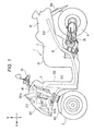
- Fig. 1 is a schematic overall side view of the vehicle 1.
- front, rear, left and right are referred to in indicating directions, they denote front, rear, left and right directions as seen from a rider who rides on the vehicle 1.
- the vehicle 1 includes a vehicle main body 2, front wheels 3 and a rear wheel 4.
- the vehicle main body 2 is made up mainly of a body frame 21, a body cover 22, a handlebar 23, a seat 24, and a power unit 25.
- the body frame 21 supports the power unit 25, the seat 24 and the like.
- the power unit 25 includes a power source such as an engine or an electric motor, a transmission and the like.
- a power source such as an engine or an electric motor, a transmission and the like.
- Fig. 1 the body frame 21 is shown by broken lines.
- the body frame 21 includes a headstock 211 that extends in an up-and-down direction, a front frame 212 that extends from the headstock 211 to the rear, and a rear frame 213.
- the headstock 211 is disposed at a front portion of the vehicle.
- a link mechanism 5 is disposed on the periphery of the headstock 211.
- the headstock 211 corresponds to a vertical frame of the invention
- the front frame 212 and the rear frame 213 correspond to a rear frame of the invention.
- the headstock 211 is supported on the front frame 212.
- a steering shaft 60 is inserted in the headstock 211 so as to turn therein.
- the steering shaft 60 extends in an up-and-down direction.
- a first penetrating portion 211a and a second penetrating portion 211b protrude from the headstock 211 to the front so as to penetrate the link mechanism 5.
- the handlebar 23 is mounted on an upper end of the steering shaft 60.
- the front frame 212 is inclined obliquely downward from a front end thereof to the rear.
- the rear frame 213 supports the seat 24 and a tail lamp.
- the body frame 21 is covered by the body cover 22 that is one of external vehicle components.
- the body cover 22 includes a front cover 221, front fenders 223, a rear fender 224, and a leg shield 225.
- the front cover 221 is positioned ahead of the seat 24.
- the front cover 221 covers at least part of the headstock 211 and the link mechanism 5.
- the front fenders 223 are provided individually directly above a pair of left and right front wheels 3.
- the front fenders 223 are disposed directly below the front cover 221.
- the rear fender 224 is disposed directly above the rear wheel 4.
- the leg shield 225 is provided behind the headstock 211.
- the leg shield 225 extends in the up-and-down direction.
- the leg shield 225 is disposed in front of the legs of a user who rides on the vehicle 1.
- the front wheels 3 are disposed further downwards than the headstock 211 and the link mechanism 5.
- the front wheels 3 are disposed directly below the front cover 221.
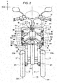
- Fig. 2 is an overall front view of the vehicle 1 with the body cover 22 removed.
- the vehicle 1 includes the handlebar 23, the steering shaft 60, the headstock 211, the pair of left and front wheels 3, and the link mechanism 5.
- the link mechanism 5 is disposed on the periphery of the headstock 211.
- the link mechanism 5 is connected to the pair of left and right front wheels 3, that is, a left front wheel 31 and a right front wheel 32.
- the link mechanism 5 is attached to the headstock 211 so as to turn thereon.
- the link mechanism 5 includes a cross member 50 and a side member 55.
- the cross member 50 has an upper cross member 51 and a lower cross member 52.
- the cross member 50 has a front cross member 50A that lies ahead of the headstock 211 and a rear cross member 50B that lies behind the headstock 211.
- the upper cross member 51 has a front upper cross member 51A that lies ahead of the headstock 211.
- the lower cross member 52 has a front lower cross member 52A that lies ahead of the headstock 211 and a rear lower cross member 52B that lies behind the headstock 211.
- the front cross portion 50A has a front upper cross member 51A and a front lower cross member 52A.
- the rear cross member 50B has a rear lower cross portion 52B.
- the side member 55 includes a left side member 53 and a right side member 54.
- the front wheels 3 include the left front wheel 31 and the right front wheels 32 that can be steered.
- the left front wheel 31 is disposed on the left of a transversely middle portion of the vehicle.
- a first front fender 223a which is one of the front fenders 223, is disposed directly above the left front wheel 31.
- the right front wheel 32 is disposed on the right of the transversely middle portion of the vehicle.
- a second front fender 223b, which is the other of the front fenders 223, is disposed above the right front wheel 32.
- the right front wheel 32 is disposed so as to be symmetric with the left front wheel 31 with respect to the transversely middle portion of the vehicle.
- a "rightward direction RF of the body frame 21" denotes a rightward direction of directions that intersect an axial direction of the headstock 211 perpendicularly when the vehicle 1 is seen from the front thereof.
- an upward direction UF of the body frame 21 denotes an upward direction of the body frame 21 with the vehicle 1 resting upright.
- the upward direction of the body frame 21 coincides with the axial direction of the headstock 211 when the vehicle 1 is seen from the front thereof.
- the rightward direction RF of the vehicle body frame 21 coincides with a rightward direction R in the horizontal direction.
- the left front wheel 31 is connected to a left shock absorber 33.
- the left front wheel 31 is connected to a lower portion of the left shock absorber 33.
- the left front wheel 31 can rotate about a rotational shaft 311.
- the rotational shaft 311 extends in a left-to-right direction of the vehicle body frame 21.
- the left front wheel 31 can turn about a turning axis 312.
- the vehicle 1 changes its traveling direction as a result of the left front wheel 31 turning about the turning axis 312.
- the right front wheel 32 is connected to a right shock absorber 34.
- the right front wheel 32 is connected to a lower portion of the right shock absorber 34.
- the right front wheel 32 can rotate about a rotational shaft 321.
- the rotational shaft 321 extends in the left-and-right direction of the body frame 21.
- the right front wheel 32 can turn about a turning axis 322.
- the vehicle 1 changes its traveling direction as a result of the right front wheel 32 turning about the turning axis 322.
- the left shock absorber 33 absorbs an impact exerted on the left front wheel 31.
- the left shock absorber 33 is disposed below the link mechanism 5 in relation to the up-and-down direction of the body frame 21.
- the left shock absorber 33 is provided between the left side portion 53 and the left front wheel 31.
- the left shock absorber 33 extends along a left steering axis N1 that extends in a direction in which the steering shaft 60 and the headstock 211 extend.
- the left shock absorber 33 is disposed on the left of the headstock 211 in relation to the left-and-right direction of the body frame 21.
- the left shock absorber 33 is disposed on the right of the left front wheel 31 in relation to the left-and-right direction of the body frame 21.
- the right shock absorber 34 absorbs an impact exerted on the right front wheel 32.
- the right shock absorber 34 is disposed below the link mechanism 5 in relation to the up-and-down direction of the body frame 21.
- the right shock absorber 34 is provided between the right side portion 54 and the right front wheel 32.
- the right shock absorber 34 extends along a right steering axis N2 in which the steering shaft 60 and the headstock 211 extend.
- the right shock absorber 34 is disposed on the right of the headstock 211 in relation to the left-and-right direction of the body frame 21.
- the right shock absorber 34 is disposed on the left of the right front wheel 32 in relation to the left-and-right direction of the body frame 21.
- the left side member 53 is disposed on the left of the headstock 211 in relation to the left-and-right direction of the body frame 21.
- the right side member 54 is disposed on the right of the headstock 211 in relation to the left-and-right direction of the body frame 21.
- the left side member 53 and the right side member 54 are cylindrical members.
- the left side member 53 and the right side member 54 extend in the up-and-down direction of the body frame 21 with the vehicle resting in the upright state.
- a first bracket 335 is provided at a lower portion of the left side member 53, and the left shock absorber 33 is connected to the first bracket 335.
- the lower portion of the left side member 53 supports the left shock absorber 33 so as to turn about the left steering axis N1.
- a second bracket 336 is provided at a lower portion of the right side member 54, and the right shock absorber 34 is connected to the second bracket 336.
- the lower portion of the right side member 54 supports the right shock absorber 34 so as to turn about the right steering axis N2.
- the upper cross member 51 is a member that extends in the left-and-right direction of the body frame 21 as seen from the front of the vehicle.
- the upper cross member 51 is provided further forwards to the front of the vehicle than the headstock 211.
- a first through hole 513 is provided in a middle portion of the upper cross member 51 in the left-and-right direction of the body frame 21, and a pair of bearings, that is, an upper left bearing 512 and an upper right bearing 512 are provided at both sides of the upper cross member 51 in the left-and-right direction of the body frame 21.
- the first penetrating portion 211 a that extends from the headstock 211 is caused to penetrate through the first through hole 513.
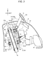
- Fig. 3 is a right side view of a front portion of the vehicle.
- an upper middle bearing 511 is provided between the first penetrating portion 211a and the first through hole 513.
- the upper cross member 51 turns about an upper middle axis M1 that constitutes the center of the upper middle bearing 511 relative to the headstock 211.
- the first through hole 513 includes the upper middle axis M1 of the upper cross member 51. This upper middle axis M1 is inclined relative to the horizontal direction so as to be slightly higher at the front.
- the upper cross member 51 is connected to an upper portion of the left side member 53 and an upper portion of the right side member 54 via the upper left bearing 512 and the upper right bearing 512, respectively. This allows the upper cross member 51 to turn relative to the left side member 53 and the right side member 54.
- the upper middle axis M1 that constitutes a turning center of the upper middle bearing 511, an upper left axis M2 that constitutes a turning center of the upper left bearing 512, and an upper right axis M3 that constitutes a turning center of the upper right bearing 512 are made to lie parallel to one another.
- the lower cross member 52 is provided further downwards than the upper cross member 51.
- the lower cross member 52 extends in the left-and-right direction when seen from the front of the vehicle.
- a length in the left-and-right direction of the lower cross member 52 is substantially equal to a length in the left-and-right direction of the upper cross member 51.
- the lower cross member 52 is provided further downwards than the upper cross member 51.
- the lower cross member 52 includes two lower cross members that are provided so as to hold the headstock 211 therebetween from the front and the rear.
- a second through hole 523 is provided in a transversely middle portion of the lower cross member 52, and a lower left bearing 522 is provided on the left of the second through hole 523, while a lower right bearing 522 is provided on the right of the second through hole 523.
- the second penetrating portion 211 b is caused to penetrate through the second through hole 523.
- a lower middle bearing 521 is provided between the second penetrating portion 211 b and the second through hole 523. This allows the lower cross member 52 to be supported so as to turn relative to the headstock 211 by the second penetrating portion 211 b and the lower middle bearings 521.
- the lower cross members 52 turn about a lower middle axis M4 that constitutes the center of the lower middle bearings 521 relative to the headstock 211.
- the second through holes 523 include the lower middle axis M4 of the lower cross members 52.
- the lower middle axis M4 that constitutes a turning center of the lower middle bearing 521, a lower left axis M5 that constitutes a turning center of the lower left bearing 522, and a lower right axis M6 that constitutes a turning center of the lower right bearing 522 are made to lie parallel to one another. Additionally, the lower middle axis M4 is provided so as to be parallel to the upper middle axis M1. In addition, with the vehicle 1 resting in the upright state, a position of the lower left bearing 522 in the left-and-right direction of the body frame 21 is set to be the same as a position of the upper left bearing 512 in the left-and-right direction of the body frame 21.
- a position of the lower right bearing 522 in the left-and-right direction of the body frame 21 is set to be the same as a position of the upper right bearing 512 in the left-and-right direction of the body frame 21.
- the lower cross members 52 are connected to a lower portion of the left side member 53 and a lower portion of the right side member 54 via the lower left bearings 522 and the lower right bearings 522, respectively. This allows the lower cross members 52 to turn relative to the left side member 53 and the right side member 54.
- the link mechanism 5 can be deformed within a plane that contains the upper cross member 51, the lower cross member 52, the left side member 53 and the right side member 54. It is noted that the link mechanism 5 is attached to the headstock 211. Because of this, even though the steering shaft 60 turns as the handlebar 23 is steered, the link mechanism 5 does not turn relative to the body frame 21.
- the tie-rod 6 turns together with the steering shaft 60 and transfers the turn of the steering shaft 60 to the left front wheel 31 and the right front wheel 32. By doing so, the left front wheel 31 and the right front wheel 32 can be steered by the handlebar 23.
- the tie-rod 6 is provided ahead of the headstock 211.
- the tie-rod 6 extends in the left-and-right direction of the body frame 21.
- the tie-rod 6 is disposed below the lower cross members 52 and above the left front wheel 31 and the right front wheel 32.
- the tie-rod 6 is connected to a lower portion of the steering shaft 60. When the steering shaft 60 is turned, the tie-rod 6 moves laterally to the left or right.
- the first bracket 335 is provided at the lower portion of the left side member 53.
- the first bracket 335 is connected to the left shock absorber 33.
- the first bracket 335 is provided so as to turn relative to the left side member 53.
- the tie-rod 6 is also provided on the first bracket 335 so as to turn relative to the left side member 53.
- a turning axis around which the first bracket 335 turns relative to the left side member 53 and a turning axis around which the first bracket 335 turns relative to the tie-rod 6 are parallel to the left steering axis N1 along which the left side member 53 extends.
- the second bracket 336 is provided at the lower portion of the right side member 54.
- the second bracket 336 is connected to the right shock absorber 34.
- the second bracket 336 is provided so as to turn relative to the right side member 54.
- the tie-rod 6 is also provided on the second bracket 336 so as to turn relative to the right side member 54.
- a turning axis around which the second bracket 336 turns relative to the right side member 54 and a turning axis around which the second bracket 336 turns relative to the tie-rod 6 are parallel to the right steering axis N2 along which the right side member 54 extends.
- the tie-rod 6 moves laterally to the left or right. Then, the first bracket 335 turns about the turning axis on which the first bracket 335 turns relative to the left side member 53 as the tie-rod 6 moves so. This moves a connecting portion 52b where the first bracket 335 connects to the left shock absorber 33 in the left-and-right direction, and the left front wheel 31 turns about the turning axis 312.
- first bracket 335 transfers the steering of the handlebar 23 to the left front wheel 31.
- second bracket 336 transfers the steering of the handlebar 23 to the right front wheel 32.
- a hydraulic unit 82 for use in an ABS is provided between the upper cross member 51 of the link mechanism 5 of the upper cross member 51 and the front cover 221 in relation to the direction of the upper middle axis M1.
- the hydraulic unit 82 includes a metallic casing, a flow path provided in the casing, a pump and solenoid valves.
- the hydraulic unit 82 controls a brake system, not shown, by switching paths through which brake fluid flows by the solenoid valves.
- Reference numeral 81 in Fig. 3 denotes a headlamp.
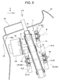
- Fig. 4 is a perspective view of the attaching bracket 7.
- Fig. 5 is a front view showing the attaching bracket 7 and the hydraulic unit 82.
- the attaching bracket 7 includes integrally a plate portion 71 and an extending portion 72 that extends obliquely from the plate portion 71.
- a first threaded hole 711 and a second threaded hole 712 are provided in the plate portion 71.
- a screw that is fixed to the first penetrating portion 211a extending from the headstock 211 is inserted through the first threaded hole 711.
- a screw that is fixed to the second penetrating portion 211b extending from the headstock 211 is inserted through the second threaded hole 712. This enables the attaching bracket 7 to be fixed to the headstock 211.
- a first stay 73 is formed at a lower portion on a side of the plate portion 71 that faces the front of the vehicle.
- a third threaded hole 731 is provided in a middle portion of the first stay 73 in the left-and-right direction of the body frame 21.
- Pair of fourth threaded holes 732 are provided outward of the third threaded hole 731 in the left-and-right direction.
- Pair of fifth threaded holes 733 are provided outward of the pair of fourth threaded holes 732 in the left-and-right direction.
- Pair of sixth threaded holes 734 are provided outward of the pair of fifth threaded holes 733 in the left-and-right direction.
- a screw is screwed through the third threaded hole 731 in the first stay 73 to fix an attaching piece 821 of the hydraulic unit 82 in place. Screws are screwed through the fourth threaded holes 732 in the first stay 73 to fix an attaching piece 822 of the hydraulic unit 82 in place.
- the hydraulic unit 82 is fixed to the attaching bracket 7 by screwing the screws through the corresponding threaded holes.
- the upper cross member 51 is supported on the headstock 211 by the upper middle bearing 511.
- a distance between the center of the upper middle bearing 511 that constitutes the connecting point where the upper cross member 51 and the headstock 211 are connected together and the center of the headstock 211 is defined herein as a link mechanism side supporting length.
- the hydraulic unit 82 is supported on the headstock 211 via the attaching bracket 7 by the screw that is inserted through the third threaded hole 731.
- a distance between the center of the third threaded hole 731 that constitutes the connecting point where the hydraulic unit 82 is connected to the headstock 211 and the center of the headstock 211 is defined as a hydraulic unit side supporting length. Then, the link mechanism side supporting length is shorter than the hydraulic unit side supporting distance.
- the link mechanism 5, which is heavier than the hydraulic unit 82, is supported on the headstock 211 in the position that lies nearer to the headstock 211 than the hydraulic unit 82. This enhances the supporting rigidity of the link mechanism 5.
- the headstock 211, the upper cross member 51 of the link mechanism 5 and the hydraulic unit 82 are aligned in this order from the rear in relation to the direction of the upper middle axis M1. As shown in Fig. 6 , as seen from the up-and-down direction of the body frame 21, a dimension of the upper cross member 51 in the left-and-right direction of the body frame 21 is larger than those of the headstock 211 and the hydraulic unit 82. Because of this, in the event that the headstock 211, the upper cross member 51 of the link mechanism 5 and the hydraulic unit 82 are arranged in this order, a space S occupied by these members takes a rhombic shape as seen from thereabove in relation to the up-and-down direction of the body frame 21.
- This rhombic shape is shaped so that its dimension in the left-and-right direction becomes smaller as it extends from the upper cross member 51 to the front and rear in relation to the front-and-rear direction of the body frame 21. Consequently, spaces S1, S2 defined on a left- and right-hand sides of portions of the space S that protrude to the front and rear from the upper cross member 51 (spaces occupied by the hydraulic unit 82 and the headstock 211) can be made use of for other applications.
- Screws are screwed through the fifth threaded holes 733 and the sixth threaded holes 734 in the first stay 73 to fix the headlamp 81 in place. This enables the headlamp 81 to be fixed to the attaching bracket 7.
- a second stay 74 and a third stay 75 are provided at a distal end of the extending portion 72.
- the windshield 222 is fixed to the second stay 74.
- the front cover 221 is fixed to the third stay 75.
- the hydraulic unit 82 is supported on the body frame 21 that supports the link mechanism 5 via the attaching bracket 7.
- the attaching bracket 7 is fixed to the first penetrating portion 211 a and the second penetrating portion 211 b that protrude to the front from the headstock 211 to penetrate through the link mechanism 5.
- Fig. 7 is an overall front view of the vehicle 1 in which the vehicle body is caused to lean at an angle T in the left-and-right direction with respect to the vertical direction from the state shown in Fig. 2 .
- the link mechanism 5 is actuated to operate, the vehicle 1 leans with respect to the vertical direction.
- the upper cross member 51 and the lower cross members 52 are translated in the horizontally left-and-right direction while the direction in which they extend is kept parallel to the road surface G.
- the upper cross member 51 and the lower cross members 52 turn about the upper left axis M2 of the upper left bearing 512 and the lower left axis M5 of the lower left bearings 522, respectively, relative to the left side portion 53.
- the upper cross member 51 and the lower cross members 52 also turn about the upper right axis M3 of the upper right bearing 512 and the lower right axis M6 of the lower right bearings 522, respectively, relative to the right side portion 54.
- the upper cross member 51, the lower cross member 52, the left side member 53 and the right side member 54 form a rectangular shape and are deformed when the vehicle is caused to lean. Then, as the vehicle is caused to lean further, the upper cross member 51, the lower cross member 52, the left side member 53, and the right side member 54 are deformed into a parallelogram.
- an area that includes the upper cross member 51, the lower cross member 52, the left side member 53 and the right side member 54 and that is defined inside the parallelogram that is formed by these four members will be called an operating space of the link mechanism 5.
- the link mechanism 5 operates so that a left end of the upper cross member 51 moves further leftwards than a left end of the lower cross member 52 in the left-and-right direction of the body frame 21.
- the link mechanism 5 operates in this way, the left shock absorber 33 and the right shock absorber 34 lean with respect to the vertical direction.
- the state of the vehicle 1 changes from the state shown in Fig. 2 to the state shown in Fig. 7 .
- the vehicle 1 according to this embodiment can be turned by causing the vehicle body to lean to the left or right while the vehicle 1 is running. Additionally, the directions of the left front wheel 31 and the right front wheel 32 can also be changed by operating the handlebar 23.
- the cross member movable area V of the cross member 50 includes a front cross member movable area VA where the front cross member 50A that includes the front upper cross member 51A and the front lower cross member 52A can move relative to the body frame 21 and a rear cross member movable area VB where the rear cross member 50B that includes the rear lower cross member 52B can move relative to the body frame 21.
- the hydraulic unit 82 is smaller than the cross member movable area V of the cross member 50 where the upper cross member 51 and the lower cross members 52 can move relative to the body frame 21.
- the hydraulic unit 82 is disposed in a position where the hydraulic unit 82 overlaps at least part of the cross member movable area V of the cross member 50 and at least part of the front cover 221 as seen in the direction of the upper middle axis M1.
- the hydraulic unit 82 is disposed between the cross member movable area V of the cross member 50 and the front cover 221 in relation to the direction of the upper middle axis M1 and is supported on the headstock 211 of the body frame 21 that supports the link mechanism 5.
- the vehicle 1 according to the embodiment that has been described above includes:
- the link mechanism 5 includes:
- the hydraulic unit 82 is smaller than the cross member movable area V of the cross member 50 that includes the upper cross member 51 and the lower cross members 52 where the upper and lower cross members can turn relative to the body frame 21 as seen from the direction of the middle axes.
- the hydraulic unit 82 is disposed in the position that overlaps at least part of the cross member movable area V of the cross member 50 and at least part of the front cover 221 as seen from the direction of the middle axes and between the cross member movable area V of the cross member 50 and the external vehicle component such as the front cover 221 in relation to the direction of the middle axes and is supported on the headstock 211 of the body frame 21 that supports the link mechanism 5. More specifically, the hydraulic unit 82 is disposed between the front cross member movable area VA and the front cover 221 in relation to the direction of the middle axes. Additionally, the hydraulic unit 82 is disposed between the rear cross member movable area VB and the front cover 221 in relation to the direction of the middle axes.
- the hydraulic unit 82 includes a plurality of components such as solenoid valves that control a fluid and a circuit board that controls the solenoid valves.
- the functional restriction limits the degree of freedom in designing the external shape of the hydraulic unit 82.
- the hydraulic unit 82 is formed into a rectangular parallelepiped having few irregularities on the external surface thereof or a shape made up of a combination of a rectangular parallelepiped and a circular cylinder. Although having fine irregularities, the hydraulic unit 82 has few large irregularities on the external surface thereof. Because of this, in disposing the hydraulic unit 82, it is necessary to ensure a large space in the vehicle.
- a vehicle including a body frame that can lean and two front wheels is smaller than a four-wheeled vehicle. Therefore, when attempting to the hydraulic unit on the vehicle including the body frame that can lean and the two front wheels, compared with a case where the hydraulic unit is disposed in the four-wheeled vehicle, there is much possibility that disposing the hydraulic unit in the vehicle enlarges the vehicle in size.
- the inventor of this invention has studied a mounting location of the hydraulic unit in the vehicle including the body frame 21 that can lean and the two front wheels, that is, on a mounting location that is suitable for disposing the hydraulic unit 82 that is large in volume and heavy in weight to some extent, that has a limited degree of freedom in designing its external shape and that has few irregularities on its external surface.
- the vehicle that includes the body frame 21 that leans and the two front wheels 31, 32 has the front portion that is large. This is attributed to the fact that the vehicle includes the two steerable front wheels 3, that is, the right front wheel 32 and the left front wheel 31 and the link mechanism 5 that supports the right front wheel 32 and the left front wheel 31 so as to be displaced relative to the body frame 21 in an up-and-down direction of the body frame 21.
- the cross member 50 and the side member 55 that make up the link mechanism 5 move largely, and the right front wheel 32 and the left front wheel 31 are displaced largely relative to the body frame 21.
- the link mechanism 5 is supported on the body frame 21 so as to turn relative thereto and moves relative to the body frame 21 and the components that are fixed to the body frame 21.
- the hydraulic unit 82 is disposed on the periphery of the link mechanism 5
- the inventor has considered that the enlargement of the front portion of the vehicle caused by the placement of the hydraulic unit 82 that is large in volume and heavy in weight and that has few irregularities on its external surface can be restricted more by disposing the hydraulic unit 82 nearer to a fixed member than by providing the hydraulic unit 82 nearer to the link mechanism 5 that is the movable member.
- the inventor has considered it difficult to dispose the hydraulic unit 82 at the front portion of the vehicle.
- the inventor has found out during the deep study on the mounting location that the cross member movable area V of the cross member 50 has a flat surface that is perpendicular to the middle axes M1, M4 as shown in Figs. 3 and 6 , while an internal surface of the external vehicle component such as the front cover 221 has a complex surface having irregularities. From this, the inventor has found out that these surface configurations create a space between the cross member movable area V of the cross member 50 that has the flat surface and the internal surface of the front cover 221 that has the irregularities. In addition, the space between the flat surface of the cross member movable area V of the cross member 50 and the irregular internal surface of the front cover 221 tends to be large due to the shapes of the two surfaces being different from each other. In addition to this, the cross member movable area V of the cross member 50 has the wide flat surface. From these facts, the inventor has found out that the space is difficult to be made use of.
- the invention has considered that the hydraulic unit 82 is disposed between the flat surface of the cross member movable area V of the cross member 50 and the irregular internal surface of the front cover 221.
- This is based on a technical idea that the disadvantage that the space is eventually created between the link mechanism 5 and the front cover 221 and the disadvantage of the hydraulic unit 82 that the hydraulic unit 82 is generally formed to have the external surface having few irregularities can be canceled out by a combination of these disadvantages.
- the hydraulic unit 82 is formed smaller than the cross member movable area V of the cross member 50 that includes the upper cross member 51 and the lower cross members 52 where the cross member 50 can move relative to the body frame 21. Additionally, the hydraulic unit 82 is disposed in the position where the hydraulic unit 82 overlaps at least part of the cross member movable area V and at least part of the front cover 221 as seen in the direction of the middle axes. As shown in Fig. 3 , the hydraulic unit 82 is disposed between the front cross member movable area VA of the front cross member 50A and the front cover 221 in relation to the direction of the middle axes.
- the hydraulic unit 82 is disposed between the cross member movable area VB of the rear cross member 50B and the front cover 221 in relation to the direction of the middle axes. Further, the hydraulic unit 82 is supported on the headstock 211 of the body frame 21 that supports the link mechanism 5.
- the cross member movable area V of the cross member 50 has the flat plane that is perpendicular to the middle axes.
- the internal surface of the external vehicle component such as the front cover 221 has the complex internal surface having irregularities in many cases.
- the front cover 221 has the internal surface in which in relation to the up-and-down direction of the body frame 21, a middle portion lies further forwards than an upper portion or a lower portion in the front-and-rear direction of the body frame 21.
- the front cover 221 has the internal surface in which in relation to the left-and-right direction of the body frame 21, a middle portion lies further forwards than a left portion or a right portion in the front-and-rear direction of the body frame 21.
- a rib 225a is provided at an upper portion of the body cover that lies at the rear of the body frame 21 to support an instrument panel, and this rib 225a ensures the supporting rigidity of the instrument panel.
- An internal surface of the portion of the body cover has a shape that is expanded towards the rear.
- terminals and the like protrude to the front. This tends to increase the space between the link mechanism 5 having the flat surface at the cross member movable area V of the cross member 50 and the external vehicle component that includes the irregular internal surface.
- the cross member movable area V of the cross member 50 has the flat surface, it is difficult to make use of the space efficiently.
- the hydraulic unit 82 that is generally formed into the shape that has few irregularities on its external surface is formed smaller than the cross member movable area V of the cross member 50 that includes the upper cross member 51 and the lower cross members 52 where the cross member 50 can move relative to the body frame 21 as seen from the direction of the middle axes, and the hydraulic unit 82 is disposed in the position that overlaps at least part of the cross member movable area V and at least part of the front cover 221 as seen from the direction of the middle axes and between the cross member movable area V and the cross member 50 and the external vehicle component (the front cover 221) in relation to the direction of the middle axes.
- the hydraulic unit 82 can be mounted on the vehicle 1, while restricting the enlargement thereof.
- the hydraulic unit 82 is disposed in the space defined between the cross member movable area V of the cross member 50 and the external vehicle component 221 and is supported on the headstock 211 of the body frame 21 that supports the link mechanism 5.
- the headstock 211 of the body frame 21 bears loads inputted from the right front wheel 32 and the left front wheel 31. Because of this, the headstock 211 of the body frame 21 is highly rigid. In supporting the hydraulic unit 82 that is heavy on the body frame 21, by making use of the high rigidity of the headstock 211, the construction for enhancing the rigidity of the body frame 21 can be simplified. This restricts the enlargement in size of the front portion of the vehicle 1.
- the hydraulic unit 82 is supported on the headstock 211 and is supported on the attaching bracket 7 that lies in a middle portion in the left-and-right direction of the body frame 21. Because of this, the hydraulic unit 82 is disposed on a center line between a center line A3 (refer to Fig. 2 ) of the left front wheel 31 and a center line of the right front wheel 32 so that at least part thereof overlaps the center line as seen from the direction of the upper middle axis M1. This prevents the hydraulic unit 82 from interfering with the link mechanism 5, the left front wheel 31 and the right front wheel 32 even through the vehicle is turned or caused to lean. Consequently, it is possible to provide the vehicle on which the hydraulic unit 82 is mounted without calling for the enhancement of the vehicle.
- the hydraulic unit 82 is supported on the attaching bracket 7 ahead of the upper cross member 51. Because of this, the hydraulic unit 82 is provided further upwards than the tie-rod 6 in the up-and-down direction of the body frame 21 as seen from the direction of the upper middle axis M1. Since the left front wheel 31 and the right front wheel 32 are provided further downwards than the tie-rod 6 in the up-and-down direction of the body frame 21, even though the vehicle is turned or is caused to lean, there is no such situation that the hydraulic unit 82 interferes with the left front wheel 31 and the right front wheel 32. Consequently, it is possible to provide the vehicle on which the hydraulic unit 82 is mounted without calling for the enhancement of the vehicle.
- FIG. 8 is a view, similar to Fig. 3 , which shows the vehicle according to the second embodiment.
- Fig. 9 is a view seen from a direction indicated by an arrow IX in Fig. 8 .
- an upper cross member 51 of a link mechanism 5 is provided ahead of a headstock 211 in relation to the direction of an upper middle axis M1.
- the hydraulic unit 82A is provided behind the headstock 211 and ahead of a leg shield 225.
- the hydraulic unit 82A is accommodated inside the leg shield 225.
- the hydraulic unit 82A is smaller than the leg shield 225 when seen from the direction of the upper middle axis M1.
- the hydraulic unit 82A is smaller than a cross member movable area V of a cross member 50 that includes the upper cross member 51 and lower cross members 52 where the cross member 50 can turn relative to a body frame 21 as seen from the direction of the upper middle axis M1.
- the hydraulic unit 82A is disposed in a position where the hydraulic unit 82A overlaps at least part of the cross member movable area V of the cross member 50 and at least part of the leg shield 225 as seen from the direction of the upper middle axis M1 and between the cross member movable area V of the cross member 50 and the leg shield 225 in relation to the direction of the upper middle axis M1 and is supported on the headstock 211 of the body frame 21 that supports the link mechanism 5.
- the hydraulic unit 82A is disposed between a cross member movable area VA of a front cross member 50A and the leg shield 225 and between a front movable area VB of a rear cross member 50B and the leg shield 225 in relation to the direction of the upper middle axis M1 and an upper middle axis M4.
- the hydraulic unit 82A is supported on the headstock 211 via an attaching bracket 7A that is fixed to the headstock 211.
- the attaching bracket 7A has a fixed portion 7A1, an extending portion 7A2, and an attaching plate portion 7A3.
- the fixed portion 7A1 is fixed to the headstock 211.
- the extending portion 7A2 protrudes from the fixed portion 7A1 to a rear side that is a side opposite to a side where the upper cross member 51 is provided.
- the attaching plate portion 7A3 is provided at a rear end of the extending portion 7A2 and extends in the direction of a surface that intersects the upper middle axis M1.
- the hydraulic unit 82A is attached to the attaching plate portion 7A3.
- the hydraulic unit 82A is disposed so as to avoid the cross member movable area V of the cross member 50. Similar to the first embodiment that has been described before, this enables the hydraulic unit 82A to be mounted on the vehicle with high supporting rigidity without calling for the enlargement of a front portion of the vehicle by making effective use of a space defined between the link mechanism 5 and the leg shield 225.
- a link mechanism side supporting length from the headstock 211 to the link mechanism 5 is shorter than a hydraulic unit side supporting length from the headstock 211 to the hydraulic unit 82A.
- the link mechanism 5, which is heavier than the hydraulic unit 82A is supported on the headstock 211 in the position that lies nearer to the headstock 211 than to the hydraulic unit 82A. This enhances the supporting rigidity of the link mechanism 5.
- the headstock 211 is disposed between the link mechanism 5 and the hydraulic unit 82A in relation to the direction of an upper middle axis M1.
- the hydraulic unit 82A and the link mechanism 5 are disposed across the headstock 211.
- the link mechanism 5 is formed larger than the headstock 211 and the hydraulic unit 82.
- a space SA that is occupied by the hydraulic unit 82A, the headstock 211 and the link mechanism 5 can be formed into a triangular shape in which the hydraulic unit 82A projects to the rear.
- spaces SA1, SA2 that are defined on a left- and right-hand sides of the hydraulic unit 82A and the headstock 211 can be used for other applications. This enhances the degree of freedom in designing the front portion of the vehicle.
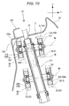
- FIG. 10 is a view, similar to Fig. 8 , which shows the vehicle according to the third embodiment.
- Fig. 11 is a view, similar to Fig. 9 , which shows the vehicle according to the third embodiment.
- the hydraulic unit 82B is disposed in a position where the hydraulic unit 82B overlaps a headstock 211 in relation to the direction of an upper middle axis M1. Additionally, a leg shield 225 is provided behind the hydraulic unit 82A and the headstock 211.
- the cross member 50 has an upper cross member 51 and a lower cross member 52.
- the cross member 50 has a front cross member 50A that lies ahead of the headstock 211 and a rear cross member 50B that lies behind the headstock 211.
- the upper cross member 51 has a front upper cross member 51A that lies ahead of the headstock 211 and a rear upper cross member 51 B that lies behind the headstock 211.
- the lower cross member 52 has a front lower cross member 52A that lies ahead of the headstock 211 and a rear lower cross member 52B that lies behind the headstock 211.
- the front cross portion 50A has a front upper cross member 51A and a front lower cross member 52A.
- the rear cross member 50B has a rear upper cross member 51B and a rear lower cross member 52B.
- the hydraulic unit 82B is disposed between the front upper cross member 51A and the rear upper cross member 51 B in relation to the upper middle axis M1.
- the hydraulic unit 82B is disposed between the front upper cross member 51A and the leg shield 225 and between the rear upper cross member 51 B and the front cover 221 in relation to the direction of the upper middle axis M1.
- the hydraulic unit 82B is disposed between the front lower cross member 52A and the leg shield 225 in relation to the upper middle axis M1.
- the hydraulic unit 82B is disposed between the rear lower cross member 52B and the front cover 221 in relation to the upper middle axis M1.
- the hydraulic unit 82B is smaller than a front cross member movable area VA of the front cross member 50A that includes the front upper cross member 51A and the front lower cross member 52A where the front cross member 50A can move relative to the body frame 21 as seen from the direction of the upper middle axis M1. Additionally, the hydraulic unit 82B is disposed in a position where the hydraulic unit 82B overlaps at least part of the cross member movable area VA of the front cross member 50A and at least part of the leg shield 225 as seen in the direction of the upper middle axis M1. In addition, the hydraulic unit 82B is disposed between the front upper cross member 51A and the leg shield 225 in relation to the direction of the upper middle axis M1 and is supported on the headstock 211 of the body frame 21 that supports the link mechanism 5.
- the hydraulic unit 82B is disposed between the front cross member movable area VA of the front cross member 50A that includes the front upper cross member 51A and the front lower cross member 52A where the front cross member 50A can move relative to the body frame 21 and the leg shield 225 in relation to the direction of the upper middle axis M1 and is supported on the headstock 211 of the body frame 21 that supports the link mechanism 5.
- the hydraulic unit 82B is smaller than a cross member movable area VB of the rear cross member 50B that includes the rear upper cross member 51 B and the rear lower cross member 52B where the rear cross member 50B can move relative to the body frame 21 as seen from the direction of the upper middle axis M1.
- the hydraulic unit 82B is disposed in a position where the hydraulic unit 82B overlaps at least part of the cross member movable area VB of the rear cross member 50B and at least part of the leg shield 225 as seen from the direction of the upper middle axis M1.
- the hydraulic unit 82B is disposed between the rear upper cross member 51 B and the front cover 221 in relation to the direction of the upper middle axis M1 and is supported on the headstock 211 of the body frame 21 that supports the link mechanism 5.
- the hydraulic unit 82B is disposed between the cross member movable area VB of the rear cross member 50B that includes the rear upper cross member 51 B and the rear lower cross member 52B where the rear cross member 50B can move relative to the body frame 21 and the front cover 221 in relation to the direction of the upper middle axis M1 and is supported on the headstock 211 of the body frame 21 that supports the link mechanism 5.
- the hydraulic unit 82B is supported on the headstock 211 via an attaching bracket 7B that is fixed to the headstock 211.
- the attaching bracket 7B has a fixed portion 7B1 and an attaching plate portion 7B2.
- the fixed portion 7B1 is fixed to the headstock 211.
- the attaching plate portion 7B2 extends from the fixed portion 7A1 in a left-and-right direction of the body frame 21. Additionally, the attaching plate portion 7B2 is a plate member that lies parallel to a surface that intersects the upper middle axis M1 perpendicularly.
- the hydraulic unit 82B is attached to the attaching plate portion 7B2.
- the hydraulic unit 82B is disposed so as to avoid a space where an operation space of the link mechanism 5 expands when the link mechanism 5 operates. This enables the hydraulic unit 82B to be mounted on the vehicle with high supporting rigidity without calling for the enlargement of a front portion of the vehicle by disposing the hydraulic unit 82B by making effective use of a space defined between the link mechanism 5 and the front cover 221 or the leg shield 225.
- the upper cross member 51 of the link mechanism 5 is formed larger than the hydraulic unit 82B.
- the hydraulic unit 82B is disposed on the right of the headstock 211 in the left-and-right direction of the body frame.
- the hydraulic unit 82B is disposed in an interior of a space B that is occupied by the upper cross member 51 of the link mechanism 5 and the headstock 211 in relation to the direction of an upper middle axis A1.
- the length of the space occupied by the upper cross member 51 and the hydraulic unit 82B can be shortened further in relation to the direction of the upper middle axis M1. This enhances further the degree of freedom of the space at the front portion of the vehicle in relation to the direction of the upper middle axis M1.
- the hydraulic unit 82B may, of course, be disposed on the left of the headstock 211 in the left-and-right direction of the body frame 21.
- the invention is not limited thereto.
- the invention can be applied to a vehicle that has a link mechanism including a middle cross member between an upper cross member and a lower cross member.
- the upper cross member 51 and the lower cross member 52 are described as being made up of the members that extend continuously in the left-and-right direction, the invention is not limited thereto.
- the upper cross member and the lower cross member may each be made up of a member that extends rightwards from the headstock 211 and a member that extends leftwards from the headstock 211. As this occurs, those members may be configured so as to turn on a turning axis or may be configured so as to turn on different turning axis.
- the upper cross member and the lower cross member may each be made up of a member that is divided into two in the left-and-right direction or two or more members.
- the members that make up the link mechanism 5 may each be made up of a linear member or a member having a curved shape or any other appropriate shape.
- the upper cross member 51 may include a front upper member and a rear upper cross member that hold the headstock 211 therebetween.
- the hydraulic unit 82, 82A, 82B is disposed between either of the front upper cross member and the rear upper cross member and the external vehicle component in relation to the direction of the upper middle axis M1, as has been described above, it is possible to provide the vehicle on which the hydraulic unit 82, 82A, 82B is mounted with high supporting rigidity without calling for the enlargement of the vehicle.
- the vehicle 1 is described as having the two front wheels 31, 32, the invention can also be applied to a vehicle having two or more rear wheels.
- the vertical frame also means a frame that is curved in a position along the length thereof so that a portion that supports the link mechanism 5 extends in the up-and-down direction of the body frame 21 and a portion therebelow extends towards the rear.
- the vertical frame means not only a frame that extends in a vertical direction but also a frame that extends in the up-and-down direction while being inclined in the front-and-rear direction to support the link mechanism.
- the vertical frame and the rear frame that extends from the vertical frame to the rear may be made up of an integral member.
- the invention is not limited thereto.
- the external vehicle component is a member that is provided at the front portion of the vehicle so that at least part thereof is exposed to the external surface of the vehicle. It is possible to raise as the external vehicle component the body cover 22 including the front cover 221, the leg shield 225 and the like, various lamps including the headlamp 81, direction indicator lamps and the like, and the instrument panel.
- the attaching construction for attaching the hydraulic unit 82 to the headstock 211 is not limited to the attaching bracket 7, 7A, 7B.
- the hydraulic unit 82A, 82B may be attached directly to the headstock 211.
- the hydraulic unit 82, 82A, 82B may be attached to a stay that extend from the headstock 211 so as to avoid the operating space of the link mechanism 5.
- a configuration may also be adopted in which the hydraulic unit 82 is fixed to the external vehicle component such as the front cover and further, at least part of the load of this external vehicle component is supported by the vertical frame.
- parallel also includes two straight lines that are inclined within the angular range of ⁇ 40 degrees and that do not intersect each other as members.
- first straight lines that are inclined within the angular range of ⁇ 40 degrees and that do not intersect each other as members.
- first straight lines that are inclined within the angular range of ⁇ 40 degrees and that do not intersect each other as members.
- first straight lines that are inclined within the angular range of ⁇ 40 degrees and that do not intersect each other as members.
- first straight lines also includes two straight lines that are inclined within the angular range of ⁇ 40 degrees and that do not intersect each other as members.
- first straight lines that are inclined within the angular range of ⁇ 40 degrees and that do not intersect each other as members.
- first straight lines also includes two straight lines that are inclined within the angular range of ⁇ 40 degrees and that do not intersect each other as members.
- first straight lines also includes two straight lines that are inclined within the angular range of ⁇ 40 degrees and that do not intersect each other as members.
- first straight lines that
- the vehicle according to the invention is the vehicle that includes the body frame that can lean and the two front wheels.
- the number of rear wheels is not limited to one, and hence, may be two.
- the vehicle may include the body cover that covers the body frame.
- the vehicle may not include the body cover which covers the body frame.
- the power unit includes the power source.
- the power source is not limited to the engine and hence may be an electric motor.
- the right side member 53, the left side member 54 and the headstock 211 are provided in positions where they overlap one another when the body frame 21 is seen from a side thereof.
- the headstock 211 may be provided in a different position from the positions where the right side member 53 and the left side member 54 are provided in relation to the front-and-rear direction.
- angles at which the right side member 53 and the left side member 54 are inclined relative to the up-and-down direction of the body frame 21 may differ from an angle at which the headstock 211 is inclined.
- the link support portion (the headstock) may be made up of a single part or a plurality of parts.
- the parts may be joined together through welding, bonding or the like.
- the parts may be joined together with fastening members such as bolts, rivets or the like.
- the upper cross member may include an upper front cross member that is made up of a single part, an upper rear cross member that is made up of a single part and a connecting member that is provided between the upper front and rear cross members and that is made up of a plurality of parts.
- the links support portion being made up of the plurality of parts, the parts may be joined together through welding, bonding or the like. Alternatively, the parts may be joined together with fastening members such as bolts, rivets or the like.
- the lower cross portion may include a lower front cross member that is made up of a single part, a lower rear cross member that is made up of a single part and a connecting member that is provided between the lower front and rear cross members and that is made up of a plurality of parts.
- the parts may be joined together through welding, bonding or the like.
- the parts may be joined together with fastening members such as bolts, rivets or the like.
- the right side member and the left side member may each be made up of a single part or a plurality of parts.
- the parts may be joined together through welding, bonding or the like.
- the parts may be joined together with fastening members such as bolts, rivets or the like.
- the right side member and the left side member may each include a portion that is disposed ahead of the upper cross member or the lower cross member in the front-and-rear direction of the vehicle body frame and a portion that is disposed behind the upper cross member or the lower cross member in the front-and-rear direction of the vehicle body frame.
- the upper cross member or the lower cross member may be disposed between the portions that are disposed at the front of the right side member and the left side member and the portions that are disposed at the rear of the right side member and the left side member.
- the body frame has the link support portion, the connecting member (the upper front and rear frame portions), the down frame (the upper and lower frame portions) and the under frame (the lower front and rear frame portions), and these constituent parts are connected together through welding.
- the body frame of the invention is not limited to those of the embodiments.
- the body frame should have the link support portion, the upper front and rear frame portions, the upper and lower frame portions and the lower front and rear frame portions.
- the body frame may be formed integrally wholly or partially through casting.
- the upper front and rear frame portions and the upper and lower frame portions may be made up of a single member or may be made up of separate members.
- an acute angle formed by the turning axis SA of the steering shaft and the up-and-down direction of the body frame coincides with an acute angle formed by the direction in which the right shock absorber and the left shock absorber extend or contract and the up-and-down direction of the body frame.
- the invention is not limited to the embodiments.
- the acute angle formed by the turning axis of the steering shaft and the up-and-down direction of the body frame may be smaller or larger than the acute angle formed by the direction in which the right shock absorber and the left shock absorber extend or contract and the up-and-down direction of the body frame.
- the turning axis of the steering shaft and the direction in which the right shock absorber and the left shock absorber extend or contact coincide with each other.
- the invention is not limited to the embodiments.
- the turning axis of the steering shaft and the direction in which the right shock absorber and the left shock absorber extend or contact may be spaced away from each other in the front-and-rear direction.
- the turning axis of the steering shaft and the direction in which the right shock absorber and the left shock absorber extend or contact may intersect each other.
- the right front wheel and the left front wheel are supported so that their upper ends can move further upwards than an upper end of the down frame of the body frame.
- the invention is not limited to the embodiments.
- the right front wheel and the left front wheel may be supported so that their upper ends can move upwards as high as or to a height that is lower than the upper end of the down frame of the body frame in the up-and-down direction of the body frame.
- the link mechanism may include further a cross member in addition to the upper cross member and the lower cross member.
- the upper cross member and the lower cross member are so called only from their relative positional relationship in the up-and-down direction.
- the upper cross member is not necessarily an uppermost cross member of the link mechanism.
- the upper cross member means a cross member that lies upward than a cross member that lies downward thereof.
- the lower cross member is not necessarily a lowermost cross member of the link mechanism.
- the lower cross member means a cross member that lies downward than a cross member that lies upward thereof.
- the cross member may be made up of two parts of a right cross member and a left cross member. In this way, the upper cross member and the lower cross member may each include a plurality of parts as long as they still make up the link function. Further, other cross members may be provided between the upper cross member and the lower cross member.
- the link mechanism should include the upper cross member and the lower cross member.
Landscapes
- Engineering & Computer Science (AREA)
- Mechanical Engineering (AREA)
- Chemical & Material Sciences (AREA)
- Combustion & Propulsion (AREA)
- Transportation (AREA)
- Automatic Cycles, And Cycles In General (AREA)
- Vehicle Body Suspensions (AREA)
Abstract
Description
- The present invention relates to a vehicle that includes a hydraulic unit for use in an ABS.
- Vehicles including a body frame that can lean and two front wheels are known in
Patent Document 1 and the like. Such vehicles include a link mechanism at a front portion thereof. In those vehicles, the traveling direction of the vehicle can be changed by causing a vehicle body to lean. - In these vehicles, a brake lever and a master cylinder are disposed at a left portion and a right portion of a handlebar. Pipings that are connected to the master cylinder at their ends pass from upper portions of side rods of the link mechanism through interiors of the side rods to be connected to calipers of a left front wheel and a right front wheel at the other ends.
- [Non-Patent Document 1] Catalogo partidi ricambio, MP3 300 64102 ie LT Mod. ZAPM64102, Piaggio
- In the vehicle described in Non-Patent
Document 1 that includes the body frame that leans and the two front wheels, a front portion of the vehicle becomes large. This is attributed to the fact that the vehicle includes the two steerable front wheels, that is, the right front wheel and the left front wheel and the link mechanism that supports the right front wheel and the left front wheel so as to be displaced relative to the body frame in an up-and-down direction of the body frame. With the body frame leaning with respect to a vertical direction, the members that make up the link mechanism move largely, and the right front wheel and the left front wheel are displaced largely relative to the body frame. This increases the size of an external vehicle component that is provided at the front portion of the vehicle so as to avoid its interference with the link mechanism that moves largely and the right front wheel and the left front wheel that are displaced largely. As a result of this configuration, in the vehicle described in Non-PatentDocument 1 that includes the body frame that leans and the two front wheels, the front portion of the vehicle becomes large. - It is desired that an ABS (Anti-locking Brake System) is mounted on the vehicle described in Non-Patent
Document 1 that includes the body frame that leans and the two front wheels. In general, a hydraulic unit that is included in the ABS is heavier in weight and larger in volume among vehicle components that make up the vehicle, and therefore, the following problems are expected to occur. - In mounting the hydraulic unit on the vehicle, the supporting rigidity of the hydraulic unit needs to be ensured since the hydraulic unit is heavy. However, ensuring the supporting rigidity tends to enlarge or complex the supporting construction of the hydraulic unit.
- Additionally, since the volume of the hydraulic unit is large, the enlargement of the vehicle needs to be restricted by devising the positional relationship between the hydraulic unit and other vehicle components.
- To make this happen, when attempting to mount an ABS on a vehicle like the one described in Non-Patent
Document 1 that includes a body frame that leans and two front wheels, there are fears that the vehicle is enlarged. - Then, an object of the invention is to provide a vehicle including a body frame that leans and two front wheels that can restrict the enlargement of the vehicle even though a hydraulic unit is mounted.
- With a view to solving the problem, according to a mode (1) that the invention can take, there is provided a vehicle including:
- a body frame;
- a left front wheel and a right front wheel that are disposed in a left and right direction when seen from the front of the vehicle and that can be steered;
- a rear wheel that is disposed behind the left front wheel and the right front wheel;
- a hydraulic brake system that is provided on any one of the right front wheel, the left front wheel and the rear wheel;
- a left shock absorbing device that supports the left front wheel at a lower portion thereof and that absorbs an upward displacement of the left front wheel in an up-and-down direction of the body frame;
- a right shock absorbing device that supports the right front wheel at a lower portion thereof and that absorbs an upward displacement of the right front wheel in the up-and-down direction of the body frame;
- a link mechanism including:
- a right side member that supports an upper portion of the right shock absorbing device so as to turn about a right steering axis that extends in the up-and-down direction of the body frame,
- a left side member that supports an upper portion of the left shock absorbing device so as to turn about a left steering axis that is parallel to the right steering axis, and
- a plurality of cross members that support the right side member at right end portions thereof so as to turn about right axes that extend in a front-and-rear direction of the body frame and support the left side member at left end portions thereof so as to turn about left axes that are parallel to the right axes and that are supported on a link support portion of the body frame at middle portions thereof so as to turn about middle axes that are parallel to the right axes and the left axes;
- an external vehicle component of which at least part is disposed ahead of or behind the link mechanism in the front-and-rear direction of the body frame and that makes up at least part of an external surface of the vehicle; and
- a hydraulic unit that controls a braking force of a hydraulic brake system,
- wherein the hydraulic unit is smaller than a cross member movable area where the cross members move relative to the body frame as seen from the direction of the middle axes, is disposed in a position that overlaps at least part of the cross member movable area and at least part of the external vehicle component as seen from the direction of the middle axes and between the cross member movable area and the external vehicle component in relation to the direction of the middle axes, and is supported on the link support portion of the body frame that supports the link mechanism.
- According to the configuration of the mode (1), the hydraulic unit is smaller than the cross member movable area where the cross members move relative to the body frame as seen from the direction of the middle axes, and the hydraulic unit is disposed in the position that overlaps at least part of the cross member movable area and at least part of the external vehicle component as seen from the direction of the middle axes and between the cross member movable area and the external vehicle component in relation to the direction of the middle axes and is supported on the link support portion of the body frame that supports the link mechanism.
- Incidentally, a hydraulic unit includes a plurality of components such as solenoid valves that control the fluid and a circuit board that controls the solenoid valves. This increases the volume and weight of the hydraulic unit to some extent, and in addition to this, the functional restriction limits the degree of freedom in designing the external shape of the hydraulic unit. In general, a hydraulic unit is formed into a rectangular parallelepiped having few irregularities on an external surface thereof or a shape made up of a combination of a rectangular parallelepiped and a circular cylinder. Although a hydraulic unit has fine irregularities on the external surface thereof but the hydraulic unit has no large irregularities thereon. Because of this, in disposing such a hydraulic unit, it is necessary to ensure a large space. A vehicle including a body frame that can lean and two front wheels is smaller than a four-wheeled vehicle. Therefore, when attempting to the hydraulic unit on the vehicle including the body frame that can lean and the two front wheels, compared with a case where the hydraulic unit is disposed in the four-wheeled vehicle, there is much possibility that disposing the hydraulic unit in the vehicle enlarges the vehicle in size.
- Then, a study has been made on a mounting location of the hydraulic unit in the vehicle including the body frame that can lean and the two front wheels, that is, on a mounting location that is suitable for disposing the hydraulic unit that is large in volume and heavy in weight to some extent, that has a limited degree of freedom in designing its external shape and that has few irregularities on its external surface.
- In the vehicle that includes the body frame that leans and the two front wheels, the front portion of the vehicle is large. This is attributed to the fact that the vehicle includes the two steerable front wheels, that is, the right front wheel and the left front wheel and the link mechanism that supports the right front wheel and the left front wheel so as to be displaced relative to the body frame in an up-and-down direction of the body frame. With the body frame leaning with respect to a vertical direction, the members that make up the link mechanism move largely, and the right front wheel and the left front wheel are displaced largely relative to the body frame. This increases the size of an external vehicle component that is provided at the front portion of the vehicle so as to avoid its interference with the link mechanism that moves largely and the right front wheel and the left front wheel that are displaced largely. As a result of this, in the vehicle that includes the body frame that leans and the two front wheels, the front portion of the vehicle is large. Because of this, it has been considered difficult to dispose the hydraulic unit at the front portion of the vehicle.
- Moreover, the link mechanism that causes the body frame to lean is turnably supported on the body frame and moves relative to the body frame and components that are fixed to the body frame. In the event that the hydraulic unit is disposed on the periphery of the link mechanism, it becomes necessary to ensure a large space on the periphery of the link mechanism as a space where to dispose the hydraulic unit in order to avoid the interference of the hydraulic unit with the link mechanism, and this tends to enlarge the vehicle. Because of this, it is generally considered that the enlargement of the vehicle caused by the placement of the hydraulic unit that is large in volume and heavy in weight and that has few irregularities on its external surface can be restricted more by disposing the hydraulic unit close to a fixed member than by providing the hydraulic unit near the link mechanism that is the movable member.
- However, it has been found out during the deep study on the mounting location that the cross member movable area has a flat surface that is perpendicular to the middle axes, while an internal surface of the external vehicle component has a complex surface having irregularities. It has been found out that these surface configurations create a space between the cross member movable area having the flat surface and the internal surface of the external vehicle component having the irregularities. In addition, it has been found out that the space defined between the flat surface of the cross member movable area and the internal surface of the external vehicle component having the irregularities is easy to be increased because the shapes of the flat surface and the internal surface are different. Further, it has also been found out that since the cross member movable area has the flat surface that is wide, it is difficult to make use of the space efficiently.
- Then, a study has been made on the possibility of disposing the hydraulic unit in the space between the flat surface of the link mechanism and the irregular internal surface of the external vehicle component.
According to the configuration of the mode (1), the hydraulic unit is formed smaller than the cross member movable area where the cross members can move relative to the body frame as seen from the direction of the middle axes. Additionally, the hydraulic unit is disposed in the position where the hydraulic unit overlaps at least part of the cross member movable area and at least part of the external vehicle component as seen in the direction of the middle axes. The hydraulic unit is disposed between the cross member movable area of the cross member and the external vehicle component in relation to the direction of the middle axes. Further, the hydraulic unit is supported on the link support portion of the body frame that supports the link mechanism. The cross member movable area of the cross member has a plane that is perpendicular to the middle axes. - On the other hand, the internal surface of the external vehicle component has the complex internal surface having the irregularities. This tends to increase the space between the link mechanism having the perpendicular plane in the cross member movable area and the external vehicle component that includes the internal surface having the irregularities. Additionally, since the cross member movable area has the flat surface, it is difficult to make use of the cross member movable area efficiently.
- Then, the hydraulic unit that is formed into the shape that has few irregularities on its external surface is formed smaller than the cross member movable area where the cross members move relative to the body frame as seen from the direction of the middle axes, and the hydraulic unit is disposed in the position that overlaps at least part of the cross member movable area and at least part of the external vehicle component as seen from the direction of the middle axes and between the cross member movable area and the external vehicle component in relation to the direction of the middle axes. Thus, even though the hydraulic unit is mounted on the vehicle, it is possible to restrict the enlargement of the vehicle.
- Moreover, the hydraulic unit is disposed in the space between the cross member movable area of the cross member and the external vehicle component and is supported on the link support portion that supports the link mechanism. The link support portion of the body frame bears loads inputted from the right front wheel and the left front wheel. Because of this, the link support portion of the body frame is highly rigid. In supporting the hydraulic unit that is heavy on the body frame, by making use of the high rigidity of the link support portion, the construction for enhancing the rigidity of the body frame can be simplified. This restricts the enlargement in size of the front portion of the vehicle.
- Consequently, even though the hydraulic unit is mounted on the vehicle that includes the body frame that can lean and the two front wheels, it is possible to restrict the enlargement of the vehicle.
- According to a mode (2) that the invention can take, in the vehicle, the hydraulic unit may be disposed in a position lying nearer to the middle axes than the left end portions and the right end portions of the cross members as seen from the direction of the middle axes.
- According to the configuration of the mode (2), the cross members turn about the middle axes. Since the hydraulic unit is disposed in the position lying nearer to the middle axes, the cross members are made difficult to interfere with the supporting construction of the hydraulic unit when the cross members turn. This makes it easy to make the supporting construction of the hydraulic unit compact. Consequently, even though the hydraulic unit is mounted on the vehicle that includes the body frame that can lean and the two front wheels, it is possible to restrict the enlargement of the vehicle.
- According to a mode (3) that the invention can take, in the vehicle, the external vehicle component may include an external surface of which a middle portion in a left-and-right direction of the body frame lies further forwards or rearwards than a right portion or a left portion in the front-and-rear direction of the body frame, and
the hydraulic unit may be disposed between the cross member movable area and the external surface of the external vehicle component in relation to the direction of the middle axes. - According to the configuration of the mode (3), the external surface of the external vehicle component can be formed into a convex shape, a concave shape or a sloping surface in relation to the front-and-rear direction of the body frame so as to enhance the quality of the external appearance of the vehicle. Moreover, it is possible to restrict the enlargement of the vehicle while realizing the enhancement of the quality of the external appearance even though the hydraulic unit is mounted on the vehicle that includes the body frame that can lean and the two front wheels by disposing the hydraulic unit between the external surface of the external vehicle component that is formed into the convex shape, the concave shape or the sloping surface in relation to the front-and-rear direction of the body frame and the cross member movable area that has the flat surface.
- According to a mode (4) that the invention can take, in the vehicle, the external vehicle component may include an external surface of which a middle portion in the up-and-down direction of the body frame lies further forwards or rearwards than an upper portion or a lower portion in the front-and-rear direction of the body frame, and the hydraulic unit may be disposed between the cross member movable area and the external surface of the external vehicle component in relation to the direction of the middle axes.
- According to the configuration of the mode (4), the external surface of the external vehicle component can be formed into a convex shape, a concave shape or a sloping surface in relation to the front-and-rear direction of the body frame so as to enhance the quality of the external appearance of the vehicle. Moreover, it is possible to restrict the enlargement of the vehicle while realizing the enhancement of the quality of the external appearance even though the hydraulic unit is mounted on the vehicle that includes the body frame that can lean and the two front wheels by disposing the hydraulic unit between the external surface of the external vehicle component that is formed into the convex shape, the concave shape or the sloping surface in relation to the front-and-rear direction of the body frame and the cross member movable area that has the flat surface.
- According to a mode (5) that the invention can take, in the vehicle, the hydraulic unit may be such that an end face that intersects the middle axes and that lies nearer to the cross member movable area than to the external vehicle component is formed wider than an end face that intersects the middle axes and that lies nearer to the external vehicle component than to the cross member movable area.
- According to the configuration of the mode (5), the end face lying nearer to the cross member movable area having the wide flat surface is formed wider, while the end face lying nearer to the external vehicle component is formed narrower, and therefore, the hydraulic unit can be mounded on the vehicle while restricting the enlargement of the vehicle.
- According to a mode (6) that the invention can take, in the vehicle, the link mechanism may have a tie-rod that turns together with a steering shaft and that transfers the turn of the steering shaft to the left front wheel and the right front wheel, and the hydraulic unit may be provided above the tie-rod as seen from the direction of the middle axes.
- According to the configuration of the mode (6), the hydraulic unit is made difficult to interfere with the tie-rod and the like when the vehicle is steered or is caused to lean.
- According to a mode (7) that the invention can take, in the vehicle, a supporting length between the vertical frame and the link mechanism may be shorter than a supporting length between the hydraulic unit and the link support portion.
- According to the configuration of the mode (7), the supporting rigidity of the link mechanism that is heavier than the hydraulic unit on the link support portion is enhanced without the hydraulic unit interfering with the link mechanism.
- According to a mode (8) that the invention can take, in the vehicle, the link support portion, the link mechanism and the hydraulic unit may be aligned in this order in relation to the direction of the middle axes.
- In general, the link mechanism has a larger volume than those of the link support portion and the hydraulic unit. Because of this, according to the configuration of the mode (8), in the event that the link support portion, the link mechanism and the hydraulic unit are aligned in this order, a space occupied by these members becomes rectangular as seen from an up-and-down direction that is perpendicular to the turning axes. Because of this, consequently, spaces defined on a left and right sides of the portion that protrudes in a front-and-rear direction of this space can be made use of for other applications. Consequently, even though the hydraulic unit is mounted on the vehicle that includes the body frame that can lean and the two front wheels, it is possible to restrict the enlargement of the vehicle.
- According to a mode (9) that the invention can take, in the vehicle, the hydraulic unit may be smaller than the link mechanism as seen from the up-and-down direction of the body frame.
- According to the configuration of the mode (9), the space that is occupied by the link mechanism and the hydraulic unit is reduced, so that the spaced defined on the left and right sides of the portion that protrudes in the front-and-rear direction of the space can be made use of for other applications. Consequently, even though the hydraulic unit is mounted on the vehicle that includes the body frame that can lean and the two front wheels, it is possible to restrict the enlargement of the vehicle.
- According to a mode (10) that the invention can take, in the vehicle, the link support portion may be disposed between the link mechanism and the hydraulic unit in relation to the direction of the middle axes.
- According to the configuration of the mode (10), the supporting rigidity of both the link mechanism and the hydraulic unit on the link support portion can be enhanced without the hydraulic unit and the link mechanism interfering with each other.
- According to a mode (11) that the invention can take, in the vehicle, the link mechanism may be larger than the link support portion and the hydraulic unit as seen from the up-and-down direction of the body frame.
- According to the configuration of the mode (11), since the largest link mechanism is disposed at an end in relation to the direction of the middle axes, a space that is occupied by the link support portion, the link mechanism and the hydraulic unit is easy to be formed into a triangular shape as seen from the up-and-down direction that is perpendicular to the direction of the middle axes, thereby making it possible to make effective use of the space at the front portion of the vehicle. Consequently, even though the hydraulic unit is mounted on the vehicle that includes the body frame that can lean and the two front wheels, it is possible to restrict the enlargement of the vehicle.
- According to a mode (12) that the invention can take, in the vehicle, as seen from the up-and-down direction of the body frame, the link mechanism may be larger than the hydraulic unit, and the hydraulic unit may be disposed either on the left or right of the link support portion.
- According to the configuration of the mode (12), the space occupied by the hydraulic unit, the link support portion and the link mechanism can be made as small as possible. Consequently, even though the hydraulic unit is mounted on the vehicle that includes the body frame that can lean and the two front wheels, it is possible to restrict the enlargement of the vehicle.
- According to a mode (13) that the invention can take, in the vehicle, the hydraulic unit may be disposed in an interior of an area that is occupied by the link mechanism and the link support portion in relation to the middle axes.
- According to the configuration of the mode (13), the space occupied by the hydraulic unit, the link support portion and the link mechanism can be made smaller in relation to the direction of the middle axes. Consequently, even though the hydraulic unit is mounted on the vehicle that includes the body frame that can lean and the two front wheels, it is possible to restrict the enlargement of the vehicle.
- According to a mode (14) that the invention can take, in the vehicle, the hydraulic unit may be disposed on a center line between a center line of the left front wheel and a center line of the right front wheel so that at least part thereof overlaps the center line as seen from the direction of the middle axes.
- According to the configuration of the mode (14), the hydraulic unit is made difficult to interfere with the link mechanism, the front wheels and the like when the vehicle is steered or caused to lean. Consequently, even though the hydraulic unit is mounted on the vehicle that includes the body frame that can lean and the two front wheels, it is possible to restrict the enlargement of the vehicle.
-
- [
Fig. 1] Fig. 1 is a left side view of a vehicle according to an embodiment of the invention. - [
Fig. 2] Fig. 2 is an overall front view of the vehicle shown inFig. 1 with a body cover removed. - [
Fig. 3] Fig. 3 is a sectional view of a front portion of the vehicle shown inFig. 1 as seen from the right thereof. - [
Fig. 4] Fig. 4 is a perspective view of an attaching bracket. - [
Fig. 5] Fig. 5 is a front view showing the attaching bracket, a hydraulic unit and a headlamp. - [
Fig. 6] Fig. 6 is a view resulting when the front of the vehicle is seen from an up-and-down direction that is perpendicular to turning axes. - [
Fig. 7] Fig. 7 is an overall front view showing a state in which the vehicle is caused to lean. - [
Fig. 8] Fig. 8 is a view, similar toFig. 3 , which shows a second embodiment of the invention. - [
Fig. 9] Fig. 9 is a view seen from a direction indicated by an arrow IX inFig. 8 . - [
Fig. 10] Fig. 10 is a view, similar toFig. 3 , which shows a vehicle according to a third embodiment of the invention. - [
Fig. 11] Fig. 11 is a view seen from a direction indicated by an arrow XI inFig. 10 . Mode for Carrying out the Invention - Hereinafter, a
vehicle 1 that is one type of vehicle according to an embodiment of the invention will be described by reference to the drawings. In the drawings, like reference numerals are given to like or corresponding portions and the description thereof will not be made repeatedly. - In the following description, an arrow F in the drawings denotes a forward direction of the
vehicle 1. An arrow R in the drawings denotes a rightward direction of thevehicle 1. An arrow U denotes an upward direction. A widthwise or transversely middle position of the vehicle means a central position of the vehicle in a width or transverse direction thereof when the vehicle is seen from the front thereof. A widthwise lateral direction of the vehicle means a leftward or rightward direction as seen from the transversely middle position. -
Fig. 1 is a schematic overall side view of thevehicle 1. In the following description, when front, rear, left and right are referred to in indicating directions, they denote front, rear, left and right directions as seen from a rider who rides on thevehicle 1. - The
vehicle 1 includes a vehiclemain body 2,front wheels 3 and a rear wheel 4. The vehiclemain body 2 is made up mainly of abody frame 21, abody cover 22, ahandlebar 23, aseat 24, and apower unit 25. - The
body frame 21 supports thepower unit 25, theseat 24 and the like. Thepower unit 25 includes a power source such as an engine or an electric motor, a transmission and the like. InFig. 1 , thebody frame 21 is shown by broken lines. - The
body frame 21 includes aheadstock 211 that extends in an up-and-down direction, afront frame 212 that extends from theheadstock 211 to the rear, and arear frame 213. Theheadstock 211 is disposed at a front portion of the vehicle. Alink mechanism 5 is disposed on the periphery of theheadstock 211. In this embodiment, theheadstock 211 corresponds to a vertical frame of the invention, and thefront frame 212 and therear frame 213 correspond to a rear frame of the invention. - The
headstock 211 is supported on thefront frame 212. A steeringshaft 60 is inserted in theheadstock 211 so as to turn therein. The steeringshaft 60 extends in an up-and-down direction. A first penetratingportion 211a and a second penetratingportion 211b protrude from theheadstock 211 to the front so as to penetrate thelink mechanism 5. - The
handlebar 23 is mounted on an upper end of the steeringshaft 60. Thefront frame 212 is inclined obliquely downward from a front end thereof to the rear. Therear frame 213 supports theseat 24 and a tail lamp. - The
body frame 21 is covered by thebody cover 22 that is one of external vehicle components. The body cover 22 includes afront cover 221,front fenders 223, arear fender 224, and aleg shield 225. - The
front cover 221 is positioned ahead of theseat 24. Thefront cover 221 covers at least part of theheadstock 211 and thelink mechanism 5. - The
front fenders 223 are provided individually directly above a pair of left and rightfront wheels 3. Thefront fenders 223 are disposed directly below thefront cover 221. Therear fender 224 is disposed directly above the rear wheel 4. - The
leg shield 225 is provided behind theheadstock 211. Theleg shield 225 extends in the up-and-down direction. Theleg shield 225 is disposed in front of the legs of a user who rides on thevehicle 1. - The
front wheels 3 are disposed further downwards than theheadstock 211 and thelink mechanism 5. Thefront wheels 3 are disposed directly below thefront cover 221. -
Fig. 2 is an overall front view of thevehicle 1 with thebody cover 22 removed. Thevehicle 1 includes thehandlebar 23, the steeringshaft 60, theheadstock 211, the pair of left andfront wheels 3, and thelink mechanism 5. Thelink mechanism 5 is disposed on the periphery of theheadstock 211. Thelink mechanism 5 is connected to the pair of left and rightfront wheels 3, that is, aleft front wheel 31 and a rightfront wheel 32. Thelink mechanism 5 is attached to theheadstock 211 so as to turn thereon. As shown inFigs. 2 ,3 , thelink mechanism 5 includes across member 50 and aside member 55. Thecross member 50 has anupper cross member 51 and alower cross member 52. Thecross member 50 has afront cross member 50A that lies ahead of theheadstock 211 and arear cross member 50B that lies behind theheadstock 211. Theupper cross member 51 has a frontupper cross member 51A that lies ahead of theheadstock 211. Thelower cross member 52 has a frontlower cross member 52A that lies ahead of theheadstock 211 and a rearlower cross member 52B that lies behind theheadstock 211. Thefront cross portion 50A has a frontupper cross member 51A and a frontlower cross member 52A. Therear cross member 50B has a rearlower cross portion 52B. Theside member 55 includes aleft side member 53 and aright side member 54. - The
front wheels 3 include theleft front wheel 31 and the rightfront wheels 32 that can be steered. Theleft front wheel 31 is disposed on the left of a transversely middle portion of the vehicle. Afirst front fender 223a, which is one of thefront fenders 223, is disposed directly above theleft front wheel 31. Theright front wheel 32 is disposed on the right of the transversely middle portion of the vehicle. A secondfront fender 223b, which is the other of thefront fenders 223, is disposed above theright front wheel 32. Theright front wheel 32 is disposed so as to be symmetric with theleft front wheel 31 with respect to the transversely middle portion of the vehicle. - When referred to in this description, a "rightward direction RF of the
body frame 21" denotes a rightward direction of directions that intersect an axial direction of theheadstock 211 perpendicularly when thevehicle 1 is seen from the front thereof. Additionally, when referred to, an upward direction UF of thebody frame 21 denotes an upward direction of thebody frame 21 with thevehicle 1 resting upright. For example, the upward direction of thebody frame 21 coincides with the axial direction of theheadstock 211 when thevehicle 1 is seen from the front thereof. In such a state that thevehicle 1 rests in an upright state as shown inFig. 2 , the rightward direction RF of thevehicle body frame 21 coincides with a rightward direction R in the horizontal direction. Because of this, only the rightward direction R in the horizontal direction is shown inFig. 2 . In such a state that thevehicle 1 leans relative to a road surface G as shown inFig. 7 , the rightward direction RF of thebody frame 21 does not coincide with the rightward direction R in the horizontal direction, and the upward direction UF of thebody frame 21 does not coincide with an upward direction U in the vertical direction. - The
left front wheel 31 is connected to aleft shock absorber 33. Theleft front wheel 31 is connected to a lower portion of theleft shock absorber 33. Theleft front wheel 31 can rotate about arotational shaft 311. Therotational shaft 311 extends in a left-to-right direction of thevehicle body frame 21. Theleft front wheel 31 can turn about a turningaxis 312. Thevehicle 1 changes its traveling direction as a result of theleft front wheel 31 turning about the turningaxis 312. - The
right front wheel 32 is connected to aright shock absorber 34. Theright front wheel 32 is connected to a lower portion of theright shock absorber 34. Theright front wheel 32 can rotate about arotational shaft 321. Therotational shaft 321 extends in the left-and-right direction of thebody frame 21. Theright front wheel 32 can turn about a turningaxis 322. Thevehicle 1 changes its traveling direction as a result of theright front wheel 32 turning about the turningaxis 322. - The
left shock absorber 33 absorbs an impact exerted on theleft front wheel 31. Theleft shock absorber 33 is disposed below thelink mechanism 5 in relation to the up-and-down direction of thebody frame 21. Theleft shock absorber 33 is provided between theleft side portion 53 and theleft front wheel 31. Theleft shock absorber 33 extends along a left steering axis N1 that extends in a direction in which thesteering shaft 60 and theheadstock 211 extend. Theleft shock absorber 33 is disposed on the left of theheadstock 211 in relation to the left-and-right direction of thebody frame 21. Theleft shock absorber 33 is disposed on the right of theleft front wheel 31 in relation to the left-and-right direction of thebody frame 21. - The
right shock absorber 34 absorbs an impact exerted on theright front wheel 32. Theright shock absorber 34 is disposed below thelink mechanism 5 in relation to the up-and-down direction of thebody frame 21. Theright shock absorber 34 is provided between theright side portion 54 and theright front wheel 32. Theright shock absorber 34 extends along a right steering axis N2 in which thesteering shaft 60 and theheadstock 211 extend. Theright shock absorber 34 is disposed on the right of theheadstock 211 in relation to the left-and-right direction of thebody frame 21. Theright shock absorber 34 is disposed on the left of theright front wheel 32 in relation to the left-and-right direction of thebody frame 21. - The
left side member 53 is disposed on the left of theheadstock 211 in relation to the left-and-right direction of thebody frame 21. Theright side member 54 is disposed on the right of theheadstock 211 in relation to the left-and-right direction of thebody frame 21. Theleft side member 53 and theright side member 54 are cylindrical members. - The
left side member 53 and theright side member 54 extend in the up-and-down direction of thebody frame 21 with the vehicle resting in the upright state. Afirst bracket 335 is provided at a lower portion of theleft side member 53, and theleft shock absorber 33 is connected to thefirst bracket 335. The lower portion of theleft side member 53 supports theleft shock absorber 33 so as to turn about the left steering axis N1. - A
second bracket 336 is provided at a lower portion of theright side member 54, and theright shock absorber 34 is connected to thesecond bracket 336. The lower portion of theright side member 54 supports theright shock absorber 34 so as to turn about the right steering axis N2. - The
upper cross member 51 is a member that extends in the left-and-right direction of thebody frame 21 as seen from the front of the vehicle. Theupper cross member 51 is provided further forwards to the front of the vehicle than theheadstock 211. A first throughhole 513 is provided in a middle portion of theupper cross member 51 in the left-and-right direction of thebody frame 21, and a pair of bearings, that is, an upper left bearing 512 and an upper right bearing 512 are provided at both sides of theupper cross member 51 in the left-and-right direction of thebody frame 21. The first penetratingportion 211 a that extends from theheadstock 211 is caused to penetrate through the first throughhole 513. -
Fig. 3 is a right side view of a front portion of the vehicle. As shown inFig. 3 , an upper middle bearing 511 is provided between the first penetratingportion 211a and the first throughhole 513. This allows theupper cross member 51 to be supported so as to turn relative to theheadstock 211 by the first penetratingportion 211 a and the uppermiddle bearing 511. Theupper cross member 51 turns about an upper middle axis M1 that constitutes the center of the upper middle bearing 511 relative to theheadstock 211. The first throughhole 513 includes the upper middle axis M1 of theupper cross member 51. This upper middle axis M1 is inclined relative to the horizontal direction so as to be slightly higher at the front. - The
upper cross member 51 is connected to an upper portion of theleft side member 53 and an upper portion of theright side member 54 via the upperleft bearing 512 and the upper right bearing 512, respectively. This allows theupper cross member 51 to turn relative to theleft side member 53 and theright side member 54. The upper middle axis M1 that constitutes a turning center of the uppermiddle bearing 511, an upper left axis M2 that constitutes a turning center of the upper left bearing 512, and an upper right axis M3 that constitutes a turning center of the upper right bearing 512 are made to lie parallel to one another. - Returning to
Fig. 2 , thelower cross member 52 is provided further downwards than theupper cross member 51. Thelower cross member 52 extends in the left-and-right direction when seen from the front of the vehicle. A length in the left-and-right direction of thelower cross member 52 is substantially equal to a length in the left-and-right direction of theupper cross member 51. Thelower cross member 52 is provided further downwards than theupper cross member 51. Thelower cross member 52 includes two lower cross members that are provided so as to hold theheadstock 211 therebetween from the front and the rear. - A second through
hole 523 is provided in a transversely middle portion of thelower cross member 52, and a lowerleft bearing 522 is provided on the left of the second throughhole 523, while a lowerright bearing 522 is provided on the right of the second throughhole 523. The second penetratingportion 211 b is caused to penetrate through the second throughhole 523. - As shown in
Fig. 3 , a lowermiddle bearing 521 is provided between the second penetratingportion 211 b and the second throughhole 523. This allows thelower cross member 52 to be supported so as to turn relative to theheadstock 211 by the second penetratingportion 211 b and the lowermiddle bearings 521. Thelower cross members 52 turn about a lower middle axis M4 that constitutes the center of the lowermiddle bearings 521 relative to theheadstock 211. The second throughholes 523 include the lower middle axis M4 of thelower cross members 52. - The lower middle axis M4 that constitutes a turning center of the lower
middle bearing 521, a lower left axis M5 that constitutes a turning center of the lowerleft bearing 522, and a lower right axis M6 that constitutes a turning center of the lowerright bearing 522 are made to lie parallel to one another. Additionally, the lower middle axis M4 is provided so as to be parallel to the upper middle axis M1. In addition, with thevehicle 1 resting in the upright state, a position of the lower left bearing 522 in the left-and-right direction of thebody frame 21 is set to be the same as a position of the upper left bearing 512 in the left-and-right direction of thebody frame 21. With thevehicle 1 resting in the upright state, a position of the lowerright bearing 522 in the left-and-right direction of thebody frame 21 is set to be the same as a position of the upper right bearing 512 in the left-and-right direction of thebody frame 21. - The
lower cross members 52 are connected to a lower portion of theleft side member 53 and a lower portion of theright side member 54 via the lowerleft bearings 522 and the lowerright bearings 522, respectively. This allows thelower cross members 52 to turn relative to theleft side member 53 and theright side member 54. - Thus, by being configured in the way described above, the
link mechanism 5 can be deformed within a plane that contains theupper cross member 51, thelower cross member 52, theleft side member 53 and theright side member 54. It is noted that thelink mechanism 5 is attached to theheadstock 211. Because of this, even though the steeringshaft 60 turns as thehandlebar 23 is steered, thelink mechanism 5 does not turn relative to thebody frame 21. - Next, the tie-
rod 6 will be described by reference toFig. 2 . The tie-rod 6 turns together with the steeringshaft 60 and transfers the turn of the steeringshaft 60 to theleft front wheel 31 and theright front wheel 32. By doing so, theleft front wheel 31 and theright front wheel 32 can be steered by thehandlebar 23. The tie-rod 6 is provided ahead of theheadstock 211. The tie-rod 6 extends in the left-and-right direction of thebody frame 21. The tie-rod 6 is disposed below thelower cross members 52 and above theleft front wheel 31 and theright front wheel 32. The tie-rod 6 is connected to a lower portion of the steeringshaft 60. When the steeringshaft 60 is turned, the tie-rod 6 moves laterally to the left or right. - As shown in
Fig. 2 , thefirst bracket 335 is provided at the lower portion of theleft side member 53. Thefirst bracket 335 is connected to theleft shock absorber 33. - The
first bracket 335 is provided so as to turn relative to theleft side member 53. The tie-rod 6 is also provided on thefirst bracket 335 so as to turn relative to theleft side member 53. A turning axis around which thefirst bracket 335 turns relative to theleft side member 53 and a turning axis around which thefirst bracket 335 turns relative to the tie-rod 6 are parallel to the left steering axis N1 along which theleft side member 53 extends. - The
second bracket 336 is provided at the lower portion of theright side member 54. Thesecond bracket 336 is connected to theright shock absorber 34. Thesecond bracket 336 is provided so as to turn relative to theright side member 54. The tie-rod 6 is also provided on thesecond bracket 336 so as to turn relative to theright side member 54. A turning axis around which thesecond bracket 336 turns relative to theright side member 54 and a turning axis around which thesecond bracket 336 turns relative to the tie-rod 6 are parallel to the right steering axis N2 along which theright side member 54 extends. - When the steering
shaft 60 turns as a result of thehandlebar 23 being steered, the tie-rod 6 moves laterally to the left or right. Then, thefirst bracket 335 turns about the turning axis on which thefirst bracket 335 turns relative to theleft side member 53 as the tie-rod 6 moves so. This moves a connecting portion 52b where thefirst bracket 335 connects to theleft shock absorber 33 in the left-and-right direction, and theleft front wheel 31 turns about the turningaxis 312. - In this way, the
first bracket 335 transfers the steering of thehandlebar 23 to theleft front wheel 31. Similarly, thesecond bracket 336 transfers the steering of thehandlebar 23 to theright front wheel 32. - As shown in
Fig. 3 , ahydraulic unit 82 for use in an ABS (Anti-lock Braking System) is provided between theupper cross member 51 of thelink mechanism 5 of theupper cross member 51 and thefront cover 221 in relation to the direction of the upper middle axis M1. Thehydraulic unit 82 includes a metallic casing, a flow path provided in the casing, a pump and solenoid valves. Thehydraulic unit 82 controls a brake system, not shown, by switching paths through which brake fluid flows by the solenoid valves.Reference numeral 81 inFig. 3 denotes a headlamp. - The
headlamp 81 and thehydraulic unit 82 are supported on theheadstock 211 via an attachingbracket 7.Fig. 4 is a perspective view of the attachingbracket 7.Fig. 5 is a front view showing the attachingbracket 7 and thehydraulic unit 82. As shown inFigs. 4 ,5 , the attachingbracket 7 includes integrally aplate portion 71 and an extendingportion 72 that extends obliquely from theplate portion 71. - As shown in
Fig. 4 , a first threadedhole 711 and a second threadedhole 712 are provided in theplate portion 71. A screw that is fixed to the first penetratingportion 211a extending from theheadstock 211 is inserted through the first threadedhole 711. A screw that is fixed to the second penetratingportion 211b extending from theheadstock 211 is inserted through the second threadedhole 712. This enables the attachingbracket 7 to be fixed to theheadstock 211. - A
first stay 73 is formed at a lower portion on a side of theplate portion 71 that faces the front of the vehicle. A third threadedhole 731 is provided in a middle portion of thefirst stay 73 in the left-and-right direction of thebody frame 21. Pair of fourth threadedholes 732 are provided outward of the third threadedhole 731 in the left-and-right direction. Pair of fifth threadedholes 733 are provided outward of the pair of fourth threadedholes 732 in the left-and-right direction. Pair of sixth threadedholes 734 are provided outward of the pair of fifth threadedholes 733 in the left-and-right direction. - As shown in
Fig. 5 , a screw is screwed through the third threadedhole 731 in thefirst stay 73 to fix an attachingpiece 821 of thehydraulic unit 82 in place. Screws are screwed through the fourth threadedholes 732 in thefirst stay 73 to fix an attachingpiece 822 of thehydraulic unit 82 in place. Thehydraulic unit 82 is fixed to the attachingbracket 7 by screwing the screws through the corresponding threaded holes. - The
upper cross member 51 is supported on theheadstock 211 by the uppermiddle bearing 511. A distance between the center of the upper middle bearing 511 that constitutes the connecting point where theupper cross member 51 and theheadstock 211 are connected together and the center of theheadstock 211 is defined herein as a link mechanism side supporting length. - In contrast with this, the
hydraulic unit 82 is supported on theheadstock 211 via the attachingbracket 7 by the screw that is inserted through the third threadedhole 731. A distance between the center of the third threadedhole 731 that constitutes the connecting point where thehydraulic unit 82 is connected to theheadstock 211 and the center of theheadstock 211 is defined as a hydraulic unit side supporting length. Then, the link mechanism side supporting length is shorter than the hydraulic unit side supporting distance. - Namely, in this embodiment, the
link mechanism 5, which is heavier than thehydraulic unit 82, is supported on theheadstock 211 in the position that lies nearer to theheadstock 211 than thehydraulic unit 82. This enhances the supporting rigidity of thelink mechanism 5. - The
headstock 211, theupper cross member 51 of thelink mechanism 5 and thehydraulic unit 82 are aligned in this order from the rear in relation to the direction of the upper middle axis M1. As shown inFig. 6 , as seen from the up-and-down direction of thebody frame 21, a dimension of theupper cross member 51 in the left-and-right direction of thebody frame 21 is larger than those of theheadstock 211 and thehydraulic unit 82. Because of this, in the event that theheadstock 211, theupper cross member 51 of thelink mechanism 5 and thehydraulic unit 82 are arranged in this order, a space S occupied by these members takes a rhombic shape as seen from thereabove in relation to the up-and-down direction of thebody frame 21. This rhombic shape is shaped so that its dimension in the left-and-right direction becomes smaller as it extends from theupper cross member 51 to the front and rear in relation to the front-and-rear direction of thebody frame 21. Consequently, spaces S1, S2 defined on a left- and right-hand sides of portions of the space S that protrude to the front and rear from the upper cross member 51 (spaces occupied by thehydraulic unit 82 and the headstock 211) can be made use of for other applications. - Screws are screwed through the fifth threaded
holes 733 and the sixth threadedholes 734 in thefirst stay 73 to fix theheadlamp 81 in place. This enables theheadlamp 81 to be fixed to the attachingbracket 7. - As shown in
Fig. 4 , asecond stay 74 and athird stay 75 are provided at a distal end of the extendingportion 72. As shown inFig. 3 , thewindshield 222 is fixed to thesecond stay 74. Thefront cover 221 is fixed to thethird stay 75. - In this way, the
hydraulic unit 82 is supported on thebody frame 21 that supports thelink mechanism 5 via the attachingbracket 7. The attachingbracket 7 is fixed to the first penetratingportion 211 a and the second penetratingportion 211 b that protrude to the front from theheadstock 211 to penetrate through thelink mechanism 5. -
Fig. 7 is an overall front view of thevehicle 1 in which the vehicle body is caused to lean at an angle T in the left-and-right direction with respect to the vertical direction from the state shown inFig. 2 . When thelink mechanism 5 is actuated to operate, thevehicle 1 leans with respect to the vertical direction. - As this occurs, the
upper cross member 51 and thelower cross members 52 are translated in the horizontally left-and-right direction while the direction in which they extend is kept parallel to the road surface G. Theupper cross member 51 and thelower cross members 52 turn about the upper left axis M2 of the upperleft bearing 512 and the lower left axis M5 of the lowerleft bearings 522, respectively, relative to theleft side portion 53. Theupper cross member 51 and thelower cross members 52 also turn about the upper right axis M3 of the upperright bearing 512 and the lower right axis M6 of the lowerright bearings 522, respectively, relative to theright side portion 54. - When the vehicle is seen from the front in the direction of the upper middle axis M1, with the vehicle resting in the upright state, the
upper cross member 51, thelower cross member 52, theleft side member 53 and theright side member 54 form a rectangular shape and are deformed when the vehicle is caused to lean. Then, as the vehicle is caused to lean further, theupper cross member 51, thelower cross member 52, theleft side member 53, and theright side member 54 are deformed into a parallelogram. In the following description, when seen from a direction that is parallel to an upper middle axis A1 of theupper cross member 51 and a lower middle axis A2 of thelower cross member 52, an area that includes theupper cross member 51, thelower cross member 52, theleft side member 53 and theright side member 54 and that is defined inside the parallelogram that is formed by these four members will be called an operating space of thelink mechanism 5. - In this embodiment, the
link mechanism 5 operates so that a left end of theupper cross member 51 moves further leftwards than a left end of thelower cross member 52 in the left-and-right direction of thebody frame 21. When thelink mechanism 5 operates in this way, theleft shock absorber 33 and theright shock absorber 34 lean with respect to the vertical direction. When thevehicle 1 leans to the left with respect to the vertical direction in the way described above, the state of thevehicle 1 changes from the state shown inFig. 2 to the state shown inFig. 7 . - The
vehicle 1 according to this embodiment can be turned by causing the vehicle body to lean to the left or right while thevehicle 1 is running. Additionally, the directions of theleft front wheel 31 and theright front wheel 32 can also be changed by operating thehandlebar 23. - An area where the
upper cross member 51 and thelower cross members 52 pass through thebody frame 21 when the vehicle is caused to lean to the left or right to its maximum extent will be called a cross member movable area V (refer toFigs. 2 and7 ) where thecross member 50 can move. As shown inFig. 3 , the cross member movable area V of thecross member 50 includes a front cross member movable area VA where thefront cross member 50A that includes the frontupper cross member 51A and the frontlower cross member 52A can move relative to thebody frame 21 and a rear cross member movable area VB where therear cross member 50B that includes the rearlower cross member 52B can move relative to thebody frame 21. - As shown in
Fig. 2 , as seen from the direction of the middle axes, thehydraulic unit 82 is smaller than the cross member movable area V of thecross member 50 where theupper cross member 51 and thelower cross members 52 can move relative to thebody frame 21. - Additionally, as shown in
Fig. 2 , thehydraulic unit 82 is disposed in a position where thehydraulic unit 82 overlaps at least part of the cross member movable area V of thecross member 50 and at least part of thefront cover 221 as seen in the direction of the upper middle axis M1. In addition, as shown inFig. 3 , thehydraulic unit 82 is disposed between the cross member movable area V of thecross member 50 and thefront cover 221 in relation to the direction of the upper middle axis M1 and is supported on theheadstock 211 of thebody frame 21 that supports thelink mechanism 5. - The
vehicle 1 according to the embodiment that has been described above includes: - the
body frame 21; - the
left front wheel 31 and theright front wheel 32 that are disposed in the left-and-right direction as seen from the front of thevehicle 1 and that can be steered; - the rear wheel 4 that is disposed behind the
left front wheel 31 and theright front wheel 32; - a brake system (an example of a hydraulic brake system) that is provided on any one of the
left front wheel 31, theright front wheel 32 and the rear wheel 4; - the
left shock absorber 33 that supports theleft front wheel 31 at the lower portion thereof and that absorbs the upward displacement of theleft front wheel 31 in the up-and-down direction of thebody frame 21; - the
right shock absorber 34 that supports theright front wheel 32 at the lower portion thereof and that absorbs the upward displacement of theright front wheel 32 in the up-and-down direction of thebody frame 21; - the
link mechanism 5; - the front cover 221 (an example of an external vehicle component) of which at least part is disposed ahead of or behind at least the
link mechanism 5 in the front-and-rear direction of thebody frame 21 and that makes up at least part of an external surface of the vehicle; and - the
hydraulic unit 82 that controls a braking force of the brake system. - The
link mechanism 5 includes: - the
right side member 54 that supports the upper portion of theright shock absorber 34 so as to turn about the right steering axis N2 that extends in the up-and-down direction of thebody frame 21; - the
left side member 53 that supports the upper portion of theleft shock absorber 33 so as to turn about the left steering axis N1 that is parallel to the right steering axis N2; and - the
upper cross member 51 and the lower cross members 52 (an example of a plurality of cross members) that supports theright side member 54 at the right end portions thereof so as to turn about the right axes (the upper right axis M3 and the lower right axis M6) that extend in the front-and-rear direction of thebody frame 21 and supports theleft side member 53 at the left end portions thereof so as to turn about the left axes (the upper left axis M2 and the lower left axis M5) that are parallel to the right axes and that are supported on the headstock 211 (an example of a link support portion) of thebody frame 21 at the middle portions thereof so as to turn about the middle axes (the upper middle axis M1 and the lower middle axis M4) that are parallel to the right axes and the left axes. - The
hydraulic unit 82 is smaller than the cross member movable area V of thecross member 50 that includes theupper cross member 51 and thelower cross members 52 where the upper and lower cross members can turn relative to thebody frame 21 as seen from the direction of the middle axes. - The
hydraulic unit 82 is disposed in the position that overlaps at least part of the cross member movable area V of thecross member 50 and at least part of thefront cover 221 as seen from the direction of the middle axes and between the cross member movable area V of thecross member 50 and the external vehicle component such as thefront cover 221 in relation to the direction of the middle axes and is supported on theheadstock 211 of thebody frame 21 that supports thelink mechanism 5. More specifically, thehydraulic unit 82 is disposed between the front cross member movable area VA and thefront cover 221 in relation to the direction of the middle axes. Additionally, thehydraulic unit 82 is disposed between the rear cross member movable area VB and thefront cover 221 in relation to the direction of the middle axes. - Incidentally, the
hydraulic unit 82 includes a plurality of components such as solenoid valves that control a fluid and a circuit board that controls the solenoid valves. In addition to the fact that thehydraulic unit 82 is large in volume and heavy in weight to some extent, the functional restriction limits the degree of freedom in designing the external shape of thehydraulic unit 82. In general, thehydraulic unit 82 is formed into a rectangular parallelepiped having few irregularities on the external surface thereof or a shape made up of a combination of a rectangular parallelepiped and a circular cylinder. Although having fine irregularities, thehydraulic unit 82 has few large irregularities on the external surface thereof. Because of this, in disposing thehydraulic unit 82, it is necessary to ensure a large space in the vehicle. A vehicle including a body frame that can lean and two front wheels is smaller than a four-wheeled vehicle. Therefore, when attempting to the hydraulic unit on the vehicle including the body frame that can lean and the two front wheels, compared with a case where the hydraulic unit is disposed in the four-wheeled vehicle, there is much possibility that disposing the hydraulic unit in the vehicle enlarges the vehicle in size. - Then, the inventor of this invention has studied a mounting location of the hydraulic unit in the vehicle including the
body frame 21 that can lean and the two front wheels, that is, on a mounting location that is suitable for disposing thehydraulic unit 82 that is large in volume and heavy in weight to some extent, that has a limited degree of freedom in designing its external shape and that has few irregularities on its external surface. - Firstly, the vehicle that includes the
body frame 21 that leans and the twofront wheels front wheels 3, that is, theright front wheel 32 and theleft front wheel 31 and thelink mechanism 5 that supports theright front wheel 32 and theleft front wheel 31 so as to be displaced relative to thebody frame 21 in an up-and-down direction of thebody frame 21. With thebody frame 21 leaning with respect to the vertical direction, thecross member 50 and theside member 55 that make up thelink mechanism 5 move largely, and theright front wheel 32 and theleft front wheel 31 are displaced largely relative to thebody frame 21. This increases the size of the external vehicle component such as thefront cover 221 that is provided at the front portion of the vehicle so as to avoid its interference with thelink mechanism 5 that moves largely and theright front wheel 32 and theleft front wheel 31 that are displaced largely. As a result of this, the vehicle that includes thebody frame 21 that leans and the twofront wheels - Moreover, the
link mechanism 5 is supported on thebody frame 21 so as to turn relative thereto and moves relative to thebody frame 21 and the components that are fixed to thebody frame 21. In the event that thehydraulic unit 82 is disposed on the periphery of thelink mechanism 5, it becomes necessary to ensure a large space on the periphery of thelink mechanism 5 as a space where to dispose thehydraulic unit 82 in order to avoid the interference of thehydraulic unit 82 with thelink mechanism 5, and this has caused the inventor to consider that the front portion of the vehicle is enlarged. Because of this, the inventor has considered that the enlargement of the front portion of the vehicle caused by the placement of thehydraulic unit 82 that is large in volume and heavy in weight and that has few irregularities on its external surface can be restricted more by disposing thehydraulic unit 82 nearer to a fixed member than by providing thehydraulic unit 82 nearer to thelink mechanism 5 that is the movable member. In the vehicle that has the large front portion and includes thebody frame 21 that leans and the twofront wheels hydraulic unit 82 at the front portion of the vehicle. - However, the inventor has found out during the deep study on the mounting location that the cross member movable area V of the
cross member 50 has a flat surface that is perpendicular to the middle axes M1, M4 as shown inFigs. 3 and6 , while an internal surface of the external vehicle component such as thefront cover 221 has a complex surface having irregularities. From this, the inventor has found out that these surface configurations create a space between the cross member movable area V of thecross member 50 that has the flat surface and the internal surface of thefront cover 221 that has the irregularities. In addition, the space between the flat surface of the cross member movable area V of thecross member 50 and the irregular internal surface of thefront cover 221 tends to be large due to the shapes of the two surfaces being different from each other. In addition to this, the cross member movable area V of thecross member 50 has the wide flat surface. From these facts, the inventor has found out that the space is difficult to be made use of. - Then, the invention has considered that the
hydraulic unit 82 is disposed between the flat surface of the cross member movable area V of thecross member 50 and the irregular internal surface of thefront cover 221. This is based on a technical idea that the disadvantage that the space is eventually created between thelink mechanism 5 and thefront cover 221 and the disadvantage of thehydraulic unit 82 that thehydraulic unit 82 is generally formed to have the external surface having few irregularities can be canceled out by a combination of these disadvantages. - According to the
vehicle 1 of this embodiment, as shown inFig. 2 , as seen from the direction of the middle axes, thehydraulic unit 82 is formed smaller than the cross member movable area V of thecross member 50 that includes theupper cross member 51 and thelower cross members 52 where thecross member 50 can move relative to thebody frame 21. Additionally, thehydraulic unit 82 is disposed in the position where thehydraulic unit 82 overlaps at least part of the cross member movable area V and at least part of thefront cover 221 as seen in the direction of the middle axes. As shown inFig. 3 , thehydraulic unit 82 is disposed between the front cross member movable area VA of thefront cross member 50A and thefront cover 221 in relation to the direction of the middle axes. Additionally, thehydraulic unit 82 is disposed between the cross member movable area VB of therear cross member 50B and thefront cover 221 in relation to the direction of the middle axes. Further, thehydraulic unit 82 is supported on theheadstock 211 of thebody frame 21 that supports thelink mechanism 5. The cross member movable area V of thecross member 50 has the flat plane that is perpendicular to the middle axes. - On the other hand, the internal surface of the external vehicle component such as the
front cover 221 has the complex internal surface having irregularities in many cases. For example, as shown inFig. 3 , thefront cover 221 has the internal surface in which in relation to the up-and-down direction of thebody frame 21, a middle portion lies further forwards than an upper portion or a lower portion in the front-and-rear direction of thebody frame 21. Alternatively, as shown inFig. 6 , thefront cover 221 has the internal surface in which in relation to the left-and-right direction of thebody frame 21, a middle portion lies further forwards than a left portion or a right portion in the front-and-rear direction of thebody frame 21. Additionally, arib 225a is provided at an upper portion of the body cover that lies at the rear of thebody frame 21 to support an instrument panel, and thisrib 225a ensures the supporting rigidity of the instrument panel. An internal surface of the portion of the body cover has a shape that is expanded towards the rear. Alternatively, on the internal surface of the instrument panel, terminals and the like protrude to the front. This tends to increase the space between thelink mechanism 5 having the flat surface at the cross member movable area V of thecross member 50 and the external vehicle component that includes the irregular internal surface. Additionally, since the cross member movable area V of thecross member 50 has the flat surface, it is difficult to make use of the space efficiently. - Then, the
hydraulic unit 82 that is generally formed into the shape that has few irregularities on its external surface is formed smaller than the cross member movable area V of thecross member 50 that includes theupper cross member 51 and thelower cross members 52 where thecross member 50 can move relative to thebody frame 21 as seen from the direction of the middle axes, and thehydraulic unit 82 is disposed in the position that overlaps at least part of the cross member movable area V and at least part of thefront cover 221 as seen from the direction of the middle axes and between the cross member movable area V and thecross member 50 and the external vehicle component (the front cover 221) in relation to the direction of the middle axes. Thus, thehydraulic unit 82 can be mounted on thevehicle 1, while restricting the enlargement thereof. - Moreover, the
hydraulic unit 82 is disposed in the space defined between the cross member movable area V of thecross member 50 and theexternal vehicle component 221 and is supported on theheadstock 211 of thebody frame 21 that supports thelink mechanism 5. Theheadstock 211 of thebody frame 21 bears loads inputted from theright front wheel 32 and theleft front wheel 31. Because of this, theheadstock 211 of thebody frame 21 is highly rigid. In supporting thehydraulic unit 82 that is heavy on thebody frame 21, by making use of the high rigidity of theheadstock 211, the construction for enhancing the rigidity of thebody frame 21 can be simplified. This restricts the enlargement in size of the front portion of thevehicle 1. - Consequently, even though the
hydraulic unit 82 is mounted on the vehicle that includes thebody frame 21 that can lean and the twofront wheels - In addition, in this embodiment, as shown in
Fig. 2 , thehydraulic unit 82 is supported on theheadstock 211 and is supported on the attachingbracket 7 that lies in a middle portion in the left-and-right direction of thebody frame 21. Because of this, thehydraulic unit 82 is disposed on a center line between a center line A3 (refer toFig. 2 ) of theleft front wheel 31 and a center line of theright front wheel 32 so that at least part thereof overlaps the center line as seen from the direction of the upper middle axis M1. This prevents thehydraulic unit 82 from interfering with thelink mechanism 5, theleft front wheel 31 and theright front wheel 32 even through the vehicle is turned or caused to lean. Consequently, it is possible to provide the vehicle on which thehydraulic unit 82 is mounted without calling for the enhancement of the vehicle. - In addition, in this embodiment, the
hydraulic unit 82 is supported on the attachingbracket 7 ahead of theupper cross member 51. Because of this, thehydraulic unit 82 is provided further upwards than the tie-rod 6 in the up-and-down direction of thebody frame 21 as seen from the direction of the upper middle axis M1. Since theleft front wheel 31 and theright front wheel 32 are provided further downwards than the tie-rod 6 in the up-and-down direction of thebody frame 21, even though the vehicle is turned or is caused to lean, there is no such situation that thehydraulic unit 82 interferes with theleft front wheel 31 and theright front wheel 32. Consequently, it is possible to provide the vehicle on which thehydraulic unit 82 is mounted without calling for the enhancement of the vehicle. -
- (2) According to the
vehicle 1 of this embodiment, as shown inFig. 2 , thehydraulic unit 82 is disposed in the position lying nearer to the upper middle axis M1 (or the lower middle axis M4) than to the left end portion and the right end portion of theupper cross member 51 or the left end portions and the right end portions of thelower cross members 52 as seen from the direction of the upper middle axis M1.
Theupper cross member 51 and thelower cross members 52 turn about the upper middle axis M1 and the lower middle axis M4, respectively. Since thehydraulic unit 82 is disposed in the position lying near to the upper middle axis M1 or the lower middle axis M4, when theupper cross member 51 and thelower cross members 52 turn, theupper cross member 51 and thelower cross members 52 are made difficult to interfere with the supporting construction of thehydraulic unit 82. This makes it easy to make the supporting construction of thehydraulic unit 82 compact. - (3) According to the
vehicle 1 of this embodiment, as shown inFig. 6 , the front cover 221 (an example of an external vehicle component) includes the external surface in which in relation to the left-and-right direction of thebody frame 21, the middle portion lies further forwards or rearwards than the right portion or the left portion in the front-and-rear direction of the body frame. Thehydraulic unit 82 is disposed between the cross member movable area V of thecross member 50 and thefront cover 221 in relation to the direction of the middle axis M1.
According to the configuration of (3), the external surface of thefront cover 221 is formed into a convex shape, a concave shape or a sloping surface in relation to the front-and-rear direction of thebody frame 21 so as to enhance the quality of the external appearance of thevehicle 1. Moreover, it is possible to restrict the enlargement of the vehicle while realizing the enhancement of the quality of the external appearance even though thehydraulic unit 82 is mounted on thevehicle 1 that includes thebody frame 21 that can lean and the two front wheels by disposing thehydraulic unit 82 between the external surface of thefront cover 221 that is formed into the convex shape, the concave shape or the sloping surface in relation to the front-and-rear direction of thebody frame 21 and the cross member movable area V of thecross member 50 that has the flat surface. - (4) According to the
vehicle 1 of this embodiment, as shown inFig. 3 , thefront cover 221 includes the external surface in which in relation to the up-and-down direction of thebody frame 21, the middle portion lies further forwards or rearwards than the upper portion or the lower portion in the front-and-rear direction of thebody frame 21. Thehydraulic unit 82 is disposed between the cross member movable area V of thecross member 50 and thefront cover 221 in relation to the direction of the middle axis M1.
According to the configuration of (4), the external surface of thefront cover 221 is formed into the convex shape, the concave shape or the sloping surface in relation to the front-and-rear direction of thebody frame 21 so as to enhance the quality of the external appearance of thevehicle 1. Moreover, it is possible to restrict the enlargement of the vehicle while realizing the enhancement of the quality of the external appearance even though thehydraulic unit 82 is mounted on thevehicle 1 that includes thebody frame 21 that can lean and the two front wheels by disposing thehydraulic unit 82 between the external surface of thefront cover 221 that is formed into the convex shape, the concave shape or the sloping surface in relation to the front-and-rear direction of thebody frame 21 and the cross member movable area V of thecross member 50 that has the flat surface. - (5) According to the
vehicle 1 of this embodiment, as shown inFig. 6 , thehydraulic unit 82 is such that an end face that intersects the upper middle axis M1 perpendicularly and that lies nearer to the cross member movable area V of thecross member 50 than to thefront cover 221 is formed wider than an end face that intersects the upper middle axis M1 perpendicularly and that lies nearer to thefront cover 221 than to the cross member movable area V of thecross member 50.
According to the configuration of (5), of the surfaces that thehydraulic unit 82 has, since the end face lying nearer to the cross member movable area V of thecross member 50 that has the wide flat surface is formed wider while the end face lying nearer to thefront cover 221 is formed smaller, the hydraulic unit can be mounted on the vehicle while restricting the enlargement of the vehicle. - Next, a second embodiment of the invention will be described by the use of
Figs. 8 and9 . In the following description, a feature that differs from the first embodiment that has been described above will be described, and like reference numerals will be given to like configurations to those of the first embodiment, so that the description thereof will be omitted. A vehicle of the second embodiment differs from the vehicle of the first embodiment in that ahydraulic unit 82A is disposed in a different position.Fig. 8 is a view, similar toFig. 3 , which shows the vehicle according to the second embodiment.Fig. 9 is a view seen from a direction indicated by an arrow IX inFig. 8 . - In the vehicle according to this embodiment, an
upper cross member 51 of alink mechanism 5 is provided ahead of aheadstock 211 in relation to the direction of an upper middle axis M1. Thehydraulic unit 82A is provided behind theheadstock 211 and ahead of aleg shield 225. Thehydraulic unit 82A is accommodated inside theleg shield 225. Thehydraulic unit 82A is smaller than theleg shield 225 when seen from the direction of the upper middle axis M1. Namely, thehydraulic unit 82A is smaller than a cross member movable area V of across member 50 that includes theupper cross member 51 andlower cross members 52 where thecross member 50 can turn relative to abody frame 21 as seen from the direction of the upper middle axis M1. Additionally, thehydraulic unit 82A is disposed in a position where thehydraulic unit 82A overlaps at least part of the cross member movable area V of thecross member 50 and at least part of theleg shield 225 as seen from the direction of the upper middle axis M1 and between the cross member movable area V of thecross member 50 and theleg shield 225 in relation to the direction of the upper middle axis M1 and is supported on theheadstock 211 of thebody frame 21 that supports thelink mechanism 5. In this embodiment, thehydraulic unit 82A is disposed between a cross member movable area VA of afront cross member 50A and theleg shield 225 and between a front movable area VB of arear cross member 50B and theleg shield 225 in relation to the direction of the upper middle axis M1 and an upper middle axis M4. - The
hydraulic unit 82A is supported on theheadstock 211 via an attachingbracket 7A that is fixed to theheadstock 211. The attachingbracket 7A has a fixed portion 7A1, an extending portion 7A2, and an attaching plate portion 7A3. The fixed portion 7A1 is fixed to theheadstock 211. The extending portion 7A2 protrudes from the fixed portion 7A1 to a rear side that is a side opposite to a side where theupper cross member 51 is provided. The attaching plate portion 7A3 is provided at a rear end of the extending portion 7A2 and extends in the direction of a surface that intersects the upper middle axis M1. Thehydraulic unit 82A is attached to the attaching plate portion 7A3. - By adopting this configuration, similar to the first embodiment that has been described before, the
hydraulic unit 82A is disposed so as to avoid the cross member movable area V of thecross member 50. Similar to the first embodiment that has been described before, this enables thehydraulic unit 82A to be mounted on the vehicle with high supporting rigidity without calling for the enlargement of a front portion of the vehicle by making effective use of a space defined between thelink mechanism 5 and theleg shield 225. - In addition, in this embodiment, too, a link mechanism side supporting length from the
headstock 211 to thelink mechanism 5 is shorter than a hydraulic unit side supporting length from theheadstock 211 to thehydraulic unit 82A. In this embodiment, too, thelink mechanism 5, which is heavier than thehydraulic unit 82A, is supported on theheadstock 211 in the position that lies nearer to theheadstock 211 than to thehydraulic unit 82A. This enhances the supporting rigidity of thelink mechanism 5. - In this embodiment, the
headstock 211 is disposed between thelink mechanism 5 and thehydraulic unit 82A in relation to the direction of an upper middle axis M1. In other words, thehydraulic unit 82A and thelink mechanism 5 are disposed across theheadstock 211. By adopting this configuration, there is no such situation that thehydraulic unit 82A interferes with thelink mechanism 5. In particular, it is possible to effectively restrict the interference of a brake hose or an electric wiring, not shown, that is extended from thehydraulic unit 82A with thelink mechanism 5. - Further, in this embodiment, as seen from thereabove in the up-and-down direction of the body frame 21 (a direction indicated by an arrow IX in
Fig. 8 ), as shown inFig. 9 , thelink mechanism 5 is formed larger than theheadstock 211 and thehydraulic unit 82. By doing so, a space SA that is occupied by thehydraulic unit 82A, theheadstock 211 and thelink mechanism 5 can be formed into a triangular shape in which thehydraulic unit 82A projects to the rear. By adopting this configuration, spaces SA1, SA2 that are defined on a left- and right-hand sides of thehydraulic unit 82A and theheadstock 211 can be used for other applications. This enhances the degree of freedom in designing the front portion of the vehicle. - Next, a third embodiment of the invention will be described by the use of
Figs.10 and11 . In the following description, a feature that differs from the first embodiment that has been described above will be described, and like reference numerals will be given to like configurations to those of the first embodiment, so that the description thereof will be omitted. A vehicle of the second embodiment differs from the vehicle of the first embodiment in that ahydraulic unit 82 is disposed in a different position.Fig. 10 is a view, similar toFig. 8 , which shows the vehicle according to the third embodiment.Fig. 11 is a view, similar toFig. 9 , which shows the vehicle according to the third embodiment. - In this embodiment, as shown in
Fig. 10 , thehydraulic unit 82B is disposed in a position where thehydraulic unit 82B overlaps aheadstock 211 in relation to the direction of an upper middle axis M1. Additionally, aleg shield 225 is provided behind thehydraulic unit 82A and theheadstock 211. Thecross member 50 has anupper cross member 51 and alower cross member 52. Thecross member 50 has afront cross member 50A that lies ahead of theheadstock 211 and arear cross member 50B that lies behind theheadstock 211. In addition, theupper cross member 51 has a frontupper cross member 51A that lies ahead of theheadstock 211 and a rearupper cross member 51 B that lies behind theheadstock 211. Thelower cross member 52 has a frontlower cross member 52A that lies ahead of theheadstock 211 and a rearlower cross member 52B that lies behind theheadstock 211. Thefront cross portion 50A has a frontupper cross member 51A and a frontlower cross member 52A. Therear cross member 50B has a rearupper cross member 51B and a rearlower cross member 52B. - The
hydraulic unit 82B is disposed between the frontupper cross member 51A and the rearupper cross member 51 B in relation to the upper middle axis M1. Thehydraulic unit 82B is disposed between the frontupper cross member 51A and theleg shield 225 and between the rearupper cross member 51 B and thefront cover 221 in relation to the direction of the upper middle axis M1. Thehydraulic unit 82B is disposed between the frontlower cross member 52A and theleg shield 225 in relation to the upper middle axis M1. Thehydraulic unit 82B is disposed between the rearlower cross member 52B and thefront cover 221 in relation to the upper middle axis M1. - The
hydraulic unit 82B is smaller than a front cross member movable area VA of thefront cross member 50A that includes the frontupper cross member 51A and the frontlower cross member 52A where thefront cross member 50A can move relative to thebody frame 21 as seen from the direction of the upper middle axis M1. Additionally, thehydraulic unit 82B is disposed in a position where thehydraulic unit 82B overlaps at least part of the cross member movable area VA of thefront cross member 50A and at least part of theleg shield 225 as seen in the direction of the upper middle axis M1. In addition, thehydraulic unit 82B is disposed between the frontupper cross member 51A and theleg shield 225 in relation to the direction of the upper middle axis M1 and is supported on theheadstock 211 of thebody frame 21 that supports thelink mechanism 5. - The
hydraulic unit 82B is disposed between the front cross member movable area VA of thefront cross member 50A that includes the frontupper cross member 51A and the frontlower cross member 52A where thefront cross member 50A can move relative to thebody frame 21 and theleg shield 225 in relation to the direction of the upper middle axis M1 and is supported on theheadstock 211 of thebody frame 21 that supports thelink mechanism 5. Thehydraulic unit 82B is smaller than a cross member movable area VB of therear cross member 50B that includes the rearupper cross member 51 B and the rearlower cross member 52B where therear cross member 50B can move relative to thebody frame 21 as seen from the direction of the upper middle axis M1. Additionally, thehydraulic unit 82B is disposed in a position where thehydraulic unit 82B overlaps at least part of the cross member movable area VB of therear cross member 50B and at least part of theleg shield 225 as seen from the direction of the upper middle axis M1. In addition, thehydraulic unit 82B is disposed between the rearupper cross member 51 B and thefront cover 221 in relation to the direction of the upper middle axis M1 and is supported on theheadstock 211 of thebody frame 21 that supports thelink mechanism 5. Thehydraulic unit 82B is disposed between the cross member movable area VB of therear cross member 50B that includes the rearupper cross member 51 B and the rearlower cross member 52B where therear cross member 50B can move relative to thebody frame 21 and thefront cover 221 in relation to the direction of the upper middle axis M1 and is supported on theheadstock 211 of thebody frame 21 that supports thelink mechanism 5. - The
hydraulic unit 82B is supported on theheadstock 211 via an attachingbracket 7B that is fixed to theheadstock 211. As shown inFig. 11 , the attachingbracket 7B has a fixed portion 7B1 and an attaching plate portion 7B2. The fixed portion 7B1 is fixed to theheadstock 211. The attaching plate portion 7B2 extends from the fixed portion 7A1 in a left-and-right direction of thebody frame 21. Additionally, the attaching plate portion 7B2 is a plate member that lies parallel to a surface that intersects the upper middle axis M1 perpendicularly. Thehydraulic unit 82B is attached to the attaching plate portion 7B2. - By adopting this configuration, as with the first embodiment described above, the
hydraulic unit 82B is disposed so as to avoid a space where an operation space of thelink mechanism 5 expands when thelink mechanism 5 operates. This enables thehydraulic unit 82B to be mounted on the vehicle with high supporting rigidity without calling for the enlargement of a front portion of the vehicle by disposing thehydraulic unit 82B by making effective use of a space defined between thelink mechanism 5 and thefront cover 221 or theleg shield 225. - In this embodiment, as shown in
Fig. 11 , as seen from thereabove in the up-and-down direction of the body frame 21 (a direction indicated by an arrow IX inFig. 10 ), theupper cross member 51 of thelink mechanism 5 is formed larger than thehydraulic unit 82B. Thehydraulic unit 82B is disposed on the right of theheadstock 211 in the left-and-right direction of the body frame. By adopting this configuration, the length of a space occupied by thelink mechanism 5 and thehydraulic unit 82B can be shortened in relation to the direction of the upper middle axis M1. This enhances the degree of freedom of the space at the front portion of the vehicle in relation to the direction of the upper middle axis M1. - Further, as shown in
Fig. 11 , as seen from thereabove (the direction indicated by the arrow IX inFig. 8 ) in the up-and-down direction of thebody frame 21, thehydraulic unit 82B is disposed in an interior of a space B that is occupied by theupper cross member 51 of thelink mechanism 5 and theheadstock 211 in relation to the direction of an upper middle axis A1. By adopting this configuration, the length of the space occupied by theupper cross member 51 and thehydraulic unit 82B can be shortened further in relation to the direction of the upper middle axis M1. This enhances further the degree of freedom of the space at the front portion of the vehicle in relation to the direction of the upper middle axis M1. - In this embodiment, the
hydraulic unit 82B may, of course, be disposed on the left of theheadstock 211 in the left-and-right direction of thebody frame 21. - Thus, while the invention has been described heretofore by the use of the first embodiment to the third embodiment thereof, the technical scope of the invention is not limited to the technical scopes that are descriptively defined in the embodiments. It is obvious to those skilled in the art to which the invention pertains that various alterations or improvements can be made to the embodiments.
- In the embodiments described above, while the vehicle is described as having the link mechanism that includes the
upper cross member 51 and thelower cross member 52, the invention is not limited thereto. For example, the invention can be applied to a vehicle that has a link mechanism including a middle cross member between an upper cross member and a lower cross member. - In addition, in the embodiments and the modified examples, while the
upper cross member 51 and thelower cross member 52 are described as being made up of the members that extend continuously in the left-and-right direction, the invention is not limited thereto. For example, the upper cross member and the lower cross member may each be made up of a member that extends rightwards from theheadstock 211 and a member that extends leftwards from theheadstock 211. As this occurs, those members may be configured so as to turn on a turning axis or may be configured so as to turn on different turning axis. Additionally, the upper cross member and the lower cross member may each be made up of a member that is divided into two in the left-and-right direction or two or more members. In addition, the members that make up thelink mechanism 5 may each be made up of a linear member or a member having a curved shape or any other appropriate shape. - In addition, while the
upper cross member 51 is described as being provided only at the directly ahead of theheadstock 211, similar to thelower cross member 52, theupper cross member 51 may include a front upper member and a rear upper cross member that hold theheadstock 211 therebetween. In this case, too, in the event that thehydraulic unit hydraulic unit - In addition, in the embodiments and the modified examples, while the
vehicle 1 is described as having the twofront wheels - In the embodiments, while the
headstock 211 that extends in the up-and-down direction of thebody frame 21 is described as being the vertical frame, the invention is not limited thereto. The vertical frame also means a frame that is curved in a position along the length thereof so that a portion that supports thelink mechanism 5 extends in the up-and-down direction of thebody frame 21 and a portion therebelow extends towards the rear. Additionally, the vertical frame means not only a frame that extends in a vertical direction but also a frame that extends in the up-and-down direction while being inclined in the front-and-rear direction to support the link mechanism. In addition, the vertical frame and the rear frame that extends from the vertical frame to the rear may be made up of an integral member. - In the embodiments, while the
front cover 221 and theleg shield 225 are described as being the external vehicle component, the invention is not limited thereto. The external vehicle component is a member that is provided at the front portion of the vehicle so that at least part thereof is exposed to the external surface of the vehicle. It is possible to raise as the external vehicle component thebody cover 22 including thefront cover 221, theleg shield 225 and the like, various lamps including theheadlamp 81, direction indicator lamps and the like, and the instrument panel. - The attaching construction for attaching the
hydraulic unit 82 to theheadstock 211 is not limited to the attachingbracket hydraulic unit headstock 211. Alternatively, thehydraulic unit headstock 211 so as to avoid the operating space of thelink mechanism 5. Further, a configuration may also be adopted in which thehydraulic unit 82 is fixed to the external vehicle component such as the front cover and further, at least part of the load of this external vehicle component is supported by the vertical frame. - In addition, in the embodiments, while the position where to dispose the
hydraulic unit link mechanism 5 and theheadstock 211 and the external vehicle component based on the upper middle axis A1 of theupper cross member 51, the same description will also result even in the event that the disposing position is described based on the lower middle axis M4 of thelower cross member 52. The same effect as what has been described above can be obtained even in the event that thehydraulic unit link mechanism 5 and the external vehicle component in relation to the lower middle axis M4. - When referred to in this description, "parallel" also includes two straight lines that are inclined within the angular range of ± 40 degrees and that do not intersect each other as members. When used together with a "direction" and a "member" in the invention, "along" also includes a case where what follows the direction and the member is inclined relative thereto within the angular range of ± 40 degrees. When used together with a "direction" in the invention, "extend" also includes a case where what extends is inclined relative to the direction within the angular range of ±40 degrees.
- The vehicle according to the invention is the vehicle that includes the body frame that can lean and the two front wheels. The number of rear wheels is not limited to one, and hence, may be two. The vehicle may include the body cover that covers the body frame. The vehicle may not include the body cover which covers the body frame. The power unit includes the power source. The power source is not limited to the engine and hence may be an electric motor.
- In the embodiments described above, the
right side member 53, theleft side member 54 and the headstock 211 (the link support portion) are provided in positions where they overlap one another when thebody frame 21 is seen from a side thereof. However, when thebody frame 21 is seen from the side thereof, theheadstock 211 may be provided in a different position from the positions where theright side member 53 and theleft side member 54 are provided in relation to the front-and-rear direction. Additionally, angles at which theright side member 53 and theleft side member 54 are inclined relative to the up-and-down direction of thebody frame 21 may differ from an angle at which theheadstock 211 is inclined. - The link support portion (the headstock) may be made up of a single part or a plurality of parts. In the case of the link support portion being made up of the plurality of parts, the parts may be joined together through welding, bonding or the like. Alternatively, the parts may be joined together with fastening members such as bolts, rivets or the like.
- The upper cross member may include an upper front cross member that is made up of a single part, an upper rear cross member that is made up of a single part and a connecting member that is provided between the upper front and rear cross members and that is made up of a plurality of parts. In the case of the link support portion being made up of the plurality of parts, the parts may be joined together through welding, bonding or the like. Alternatively, the parts may be joined together with fastening members such as bolts, rivets or the like.
- The lower cross portion may include a lower front cross member that is made up of a single part, a lower rear cross member that is made up of a single part and a connecting member that is provided between the lower front and rear cross members and that is made up of a plurality of parts. In the case of the link support portion being made up of the plurality of parts, the parts may be joined together through welding, bonding or the like. Alternatively, the parts may be joined together with fastening members such as bolts, rivets or the like.
- The right side member and the left side member may each be made up of a single part or a plurality of parts. In the case of the link support portion being made up of the plurality of parts, the parts may be joined together through welding, bonding or the like. Alternatively, the parts may be joined together with fastening members such as bolts, rivets or the like. The right side member and the left side member may each include a portion that is disposed ahead of the upper cross member or the lower cross member in the front-and-rear direction of the vehicle body frame and a portion that is disposed behind the upper cross member or the lower cross member in the front-and-rear direction of the vehicle body frame. The upper cross member or the lower cross member may be disposed between the portions that are disposed at the front of the right side member and the left side member and the portions that are disposed at the rear of the right side member and the left side member.
- In this embodiments, the body frame has the link support portion, the connecting member (the upper front and rear frame portions), the down frame (the upper and lower frame portions) and the under frame (the lower front and rear frame portions), and these constituent parts are connected together through welding. However, the body frame of the invention is not limited to those of the embodiments. The body frame should have the link support portion, the upper front and rear frame portions, the upper and lower frame portions and the lower front and rear frame portions. For example, the body frame may be formed integrally wholly or partially through casting. Additionally, in the body frame, the upper front and rear frame portions and the upper and lower frame portions may be made up of a single member or may be made up of separate members.
- In this embodiments, an acute angle formed by the turning axis SA of the steering shaft and the up-and-down direction of the body frame coincides with an acute angle formed by the direction in which the right shock absorber and the left shock absorber extend or contract and the up-and-down direction of the body frame. However, the invention is not limited to the embodiments. For example, the acute angle formed by the turning axis of the steering shaft and the up-and-down direction of the body frame may be smaller or larger than the acute angle formed by the direction in which the right shock absorber and the left shock absorber extend or contract and the up-and-down direction of the body frame.
- In addition, in the embodiments, the turning axis of the steering shaft and the direction in which the right shock absorber and the left shock absorber extend or contact coincide with each other. However, the invention is not limited to the embodiments. When the vehicle resting in the upright state is seen from a side thereof, the turning axis of the steering shaft and the direction in which the right shock absorber and the left shock absorber extend or contact may be spaced away from each other in the front-and-rear direction. Additionally, for example, the turning axis of the steering shaft and the direction in which the right shock absorber and the left shock absorber extend or contact may intersect each other.
- In these embodiments, the right front wheel and the left front wheel are supported so that their upper ends can move further upwards than an upper end of the down frame of the body frame. However, the invention is not limited to the embodiments. In this invention, the right front wheel and the left front wheel may be supported so that their upper ends can move upwards as high as or to a height that is lower than the upper end of the down frame of the body frame in the up-and-down direction of the body frame.
- In the invention, the link mechanism may include further a cross member in addition to the upper cross member and the lower cross member. The upper cross member and the lower cross member are so called only from their relative positional relationship in the up-and-down direction. The upper cross member is not necessarily an uppermost cross member of the link mechanism. The upper cross member means a cross member that lies upward than a cross member that lies downward thereof. The lower cross member is not necessarily a lowermost cross member of the link mechanism. The lower cross member means a cross member that lies downward than a cross member that lies upward thereof. Additionally, the cross member may be made up of two parts of a right cross member and a left cross member. In this way, the upper cross member and the lower cross member may each include a plurality of parts as long as they still make up the link function. Further, other cross members may be provided between the upper cross member and the lower cross member. The link mechanism should include the upper cross member and the lower cross member.
- The invention can be embodied in many different forms. The disclosure herein should be regarded as providing the embodiments of the principle of the invention. Based on the understanding that the preferred embodiments that are described and/or illustrated herein are not intended to limit the invention thereto, several embodiments are described and illustrated herein.
- Several illustrated embodiments of the invention are described herein. The invention is not limited to the various preferred embodiments that are described herein. The invention can include every embodiment that includes equivalent elements, modifications, deletions, combinations (for example, combinations of the characteristics of the various embodiments), improvements and/or alterations that those skilled in the art to which the invention pertains can think of. Matters limited by claims should be construed widely based on terms that are used in the claims and should not be limited to the embodiments described in this description or during the prosecution of this patent application. Those embodiments should be construed as non-exclusive. For example, in this disclosure, such terms as "preferable" and "good" are non-exclusive terms and mean that "it is preferable but does not limit the invention thereto" and "it is good but does not limit the invention thereto," respectively.
- This patent application is based on Japanese Patent Application No.
2012-278878 filed on December 21, 2012 2012-278879 filed on December 21, 2012 2013-138481 filed on July 1, 2013 -
- 1: vehicle
- 2: vehicle body
- 21: body frame
- 211: headstock
- 211 a: first penetrating portion
- 211b: second penetrating portion
- 212: front frame
- 213: rear frame
- 22: body cover
- 221: front cover
- 222: windshield
- 223: front fender
- 224: rear fender
- 225: leg shield
- 23: handlebar
- 24: seat
- 25: power unit
- 3: pair of left and right front wheels
- 31: left front wheel
- 32: right front wheel
- 335: first bracket
- 336: second bracket
- 33: left shock absorber
- 34: right shock absorber
- 4: rear wheel
- 5: link mechanism
- 51: upper cross member
- 513: first through hole
- 52: lower cross member
- 523: second through hole
- 53: left side member
- 54: right side member
- 6: tie-rod
- 60: steering shaft
- 7: attaching bracket
- 81: headlamp
- 82, 82A, 82B: hydraulic unit
- A1: upper middle axis
- A2: lower middle axis
Claims (14)
- A vehicle comprising:a body frame;a left front wheel and a right front wheel that are disposed in a left and right direction when seen from the front of the vehicle and that can be steered;a rear wheel that is disposed behind the left front wheel and the right front wheel;a hydraulic brake system that is provided on any one of the right front wheel, the left front wheel and the rear wheel;a left shock absorbing device that supports the left front wheel at a lower portion thereof and that absorbs an upward displacement of the left front wheel in an up-and-down direction of the body frame;a right shock absorbing device that supports the right front wheel at a lower portion thereof and that absorbs an upward displacement of the right front wheel in the up-and-down direction of the body frame;a link mechanism including:a right side member that supports an upper portion of the right shock absorbing device so as to turn about a right steering axis that extends in the up-and-down direction of the body frame,a left side member that supports an upper portion of the left shock absorbing device so as to turn about a left steering axis that is parallel to the right steering axis, anda plurality of cross members that support the right side member at right end portions thereof so as to turn about right axes that extend in a front-and-rear direction of the body frame and support the left side member at left end portions thereof so as to turn about left axes that are parallel to the right axes and that are supported on a link support portion of the body frame at middle portions thereof so as to turn about middle axes that are parallel to the right axes and the left axes;an external vehicle component of which at least part is disposed ahead of or behind the link mechanism in the front-and-rear direction of the body frame and that makes up at least part of an external surface of the vehicle; anda hydraulic unit that controls a braking force of a hydraulic brake system,wherein the hydraulic unit is smaller than a cross member movable area where the cross members move relative to the body frame as seen from the direction of the middle axes, is disposed in a position that overlaps at least part of the cross member movable area and at least part of the external vehicle component as seen from the direction of the middle axes and between the cross member movable area and the external vehicle component in relation to the direction of the middle axes, and is supported on the link support portion of the body frame that supports the link mechanism.
- The vehicle according to Claim 1, wherein
the hydraulic unit is disposed in a position lying nearer to the middle axes than the left end portions and the right end portions of the cross members as seen from the direction of the middle axes. - The vehicle according to Claim 1 or 2, wherein
the external vehicle component comprises an external surface of which a middle portion in a left-and-right direction of the body frame lies further forwards or rearwards than a right portion or a left portion in the front-and-rear direction of the body frame, and
the hydraulic unit is disposed between the cross member movable area and the external surface of the external vehicle component in relation to the direction of the middle axes. - The vehicle according to any one of Claims 1 to 3, wherein
the external vehicle component comprises an external surface of which a middle portion in the up-and-down direction of the body frame lies further forwards or rearwards than an upper portion or a lower portion in the front-and-rear direction of the body frame, and
the hydraulic unit is disposed between the cross member movable area and the external surface of the external vehicle component in relation to the direction of the middle axes. - The vehicle according to any one of Claims 1 to 4, wherein
the hydraulic unit is such that an end face that intersects the middle axes and that lies nearer to the cross member movable area than to the external vehicle component is formed wider than an end face that intersects the middle axes and that lies nearer to the external vehicle component than to the cross member movable area. - The vehicle according to any one of Claims 1 to 5, wherein
the link mechanism has a tie-rod that turns together with a steering shaft and that transfers the turn of the steering shaft to the left front wheel and the right front wheel, and
the hydraulic unit is provided above the tie-rod as seen from the direction of the middle axes. - The vehicle according to any one of Claims 1 to 6, wherein
a supporting length between the link support portion and the link mechanism is shorter than a supporting length between the hydraulic unit and the link support portion. - The vehicle according to any one of Claims 1 to 7, wherein
the link support portion, the link mechanism and the hydraulic unit are aligned in this order in relation to the direction of the middle axes. - The vehicle according to any one of Claims 1 to 7, wherein
the hydraulic unit may be smaller than the link mechanism as seen from the up-and-down direction of the body frame. - The vehicle according to any one of Claims 1 to 6, wherein
the body frame is disposed between the link mechanism and the hydraulic unit in relation to the direction of the middle axes. - The vehicle according to Claim 10, wherein
the link mechanism is larger than the link support portion and the hydraulic unit as seen from the up-and-down direction of the body frame. - The vehicle according to any one of Claims 1 to 6, wherein
as seen from the up-and-down direction of the body frame, the link mechanism is larger than the hydraulic unit, and the hydraulic unit is disposed further leftwards or rightwards of the body frame than the link support portion. - The vehicle according to Claim 12, wherein
the hydraulic unit is disposed in an interior of an area that is occupied by the link mechanism and the link support portion in relation to the direction of the middle axes. - The vehicle according to Claim 2, wherein
the hydraulic unit is disposed on a center line between a center line of the left front wheel and a center line of the right front wheel so that at least part thereof overlaps the center line as seen from the direction of the middle axes.
Applications Claiming Priority (4)
| Application Number | Priority Date | Filing Date | Title |
|---|---|---|---|
| JP2012278878 | 2012-12-21 | ||
| JP2012278879 | 2012-12-21 | ||
| JP2013138481 | 2013-07-01 | ||
| PCT/JP2013/084284 WO2014098227A1 (en) | 2012-12-21 | 2013-12-20 | Vehicle |
Publications (3)
| Publication Number | Publication Date |
|---|---|
| EP2923933A1 true EP2923933A1 (en) | 2015-09-30 |
| EP2923933A4 EP2923933A4 (en) | 2016-01-13 |
| EP2923933B1 EP2923933B1 (en) | 2018-10-03 |
Family
ID=50978541
Family Applications (2)
| Application Number | Title | Priority Date | Filing Date |
|---|---|---|---|
| EP13865581.6A Active EP2923931B1 (en) | 2012-12-21 | 2013-12-20 | Vehicle |
| EP13863762.4A Active EP2923933B1 (en) | 2012-12-21 | 2013-12-20 | Vehicle |
Family Applications Before (1)
| Application Number | Title | Priority Date | Filing Date |
|---|---|---|---|
| EP13865581.6A Active EP2923931B1 (en) | 2012-12-21 | 2013-12-20 | Vehicle |
Country Status (10)
| Country | Link |
|---|---|
| US (2) | US9434439B2 (en) |
| EP (2) | EP2923931B1 (en) |
| JP (1) | JPWO2014098236A1 (en) |
| CN (2) | CN104487332B (en) |
| AP (1) | AP2015008544A0 (en) |
| BR (1) | BR112015014908B1 (en) |
| ES (2) | ES2759322T3 (en) |
| MX (1) | MX352173B (en) |
| TW (2) | TWI530426B (en) |
| WO (2) | WO2014098236A1 (en) |
Families Citing this family (28)
| Publication number | Priority date | Publication date | Assignee | Title |
|---|---|---|---|---|
| WO2014065385A1 (en) * | 2012-10-25 | 2014-05-01 | ヤマハ発動機株式会社 | Vehicle |
| US9340249B2 (en) * | 2012-12-19 | 2016-05-17 | Yamaha Hatsudoki Kabushiki Kaisha | Vehicle |
| WO2015002172A1 (en) * | 2013-07-01 | 2015-01-08 | ヤマハ発動機株式会社 | Vehicle |
| MX2015017478A (en) * | 2013-07-01 | 2016-03-21 | Yamaha Motor Co Ltd | Vehicle. |
| US9821874B2 (en) * | 2013-07-01 | 2017-11-21 | Yamaha Hatsudoki Kabushiki Kaisha | Vehicle |
| JP6057939B2 (en) * | 2014-03-28 | 2017-01-11 | 本田技研工業株式会社 | Manufacturing method of body frame of saddle riding type vehicle |
| EP3202651B1 (en) * | 2014-09-29 | 2019-07-24 | Yamaha Hatsudoki Kabushiki Kaisha | Vehicle |
| CN104554550B (en) * | 2014-11-03 | 2017-01-25 | 宁波宝驹动力科技有限公司 | Radial rotation rollover prevention mechanism for frame of tricycle |
| US10286970B2 (en) | 2015-09-30 | 2019-05-14 | Yamaha Hatsudoki Kabushiki Kaisha | Vehicle |
| JP6515197B2 (en) * | 2015-11-13 | 2019-05-15 | ヤマハ発動機株式会社 | Lean vehicle |
| JP6293857B2 (en) * | 2016-03-18 | 2018-03-14 | ヤマハ発動機株式会社 | Lean vehicle |
| JP2017170930A (en) * | 2016-03-18 | 2017-09-28 | ヤマハ発動機株式会社 | vehicle |
| JP2017170931A (en) * | 2016-03-18 | 2017-09-28 | ヤマハ発動機株式会社 | vehicle |
| WO2017208992A1 (en) * | 2016-05-30 | 2017-12-07 | ヤマハ発動機株式会社 | Vehicle |
| IT201600071697A1 (en) * | 2016-07-08 | 2018-01-08 | Piaggio & C Spa | Front axle of tilting motor vehicle and relative motor vehicle |
| USD819498S1 (en) * | 2017-01-03 | 2018-06-05 | Zhejiang Doohan Technology Co., Ltd. | Reverse trike vehicle |
| CN107054528B (en) * | 2017-02-15 | 2023-01-13 | 天津内燃机研究所(天津摩托车技术中心) | Front wheel rocker structure and front wheel swinging and tilting mechanism of double-front-wheel motorcycle |
| JP2018144697A (en) * | 2017-03-07 | 2018-09-20 | ヤマハ発動機株式会社 | vehicle |
| JP2018144698A (en) * | 2017-03-07 | 2018-09-20 | ヤマハ発動機株式会社 | vehicle |
| CN107031769B (en) * | 2017-03-22 | 2022-11-22 | 天津内燃机研究所(天津摩托车技术中心) | Front wheel rocker arm structure and front wheel swinging and inclining structure of double-front-wheel motorcycle |
| JP6547194B2 (en) * | 2017-03-29 | 2019-07-24 | 本田技研工業株式会社 | Swing lock operation part structure of saddle-ride type vehicle |
| JP6568895B2 (en) * | 2017-05-31 | 2019-08-28 | 本田技研工業株式会社 | Saddle-type small vehicle, and vehicle body frame rigidity adjusting device |
| USD849601S1 (en) * | 2017-10-06 | 2019-05-28 | Zhejiang Doohan Technology Co., Ltd. | Three-wheeled motorcycle |
| USD872656S1 (en) * | 2017-11-06 | 2020-01-14 | Quadro Vehicles S.A. | Motor scooter |
| IT201800020347A1 (en) * | 2018-12-20 | 2020-06-20 | Piaggio & C Spa | COMPACT SYSTEM FOR ABS INSTALLABLE ON A MOTORCYCLE AND MOTORCYCLE INCLUDING THIS SYSTEM |
| JP7545980B2 (en) | 2019-08-30 | 2024-09-05 | ヤマハ発動機株式会社 | Lean Vehicle |
| WO2021039991A1 (en) * | 2019-08-30 | 2021-03-04 | ヤマハ発動機株式会社 | Leaning vehicle |
| IT202100015341A1 (en) * | 2021-06-11 | 2022-12-11 | Piaggio & C Spa | ROLLING SADDLE VEHICLE WITH NON ROLLING FRONT FAIRING. |
Family Cites Families (37)
| Publication number | Priority date | Publication date | Assignee | Title |
|---|---|---|---|---|
| US2990215A (en) * | 1959-06-29 | 1961-06-27 | Checker Motors Corp | Tail gate mounting for automotive vehicles |
| US4088199A (en) | 1976-02-23 | 1978-05-09 | Wolfgang Trautwein | Stabilized three-wheeled vehicle |
| US4351410A (en) * | 1980-07-17 | 1982-09-28 | Townsend Engineering Company | Self-balancing wheeled vehicle |
| US4740004A (en) * | 1986-06-09 | 1988-04-26 | Mcmullen Wayne W | Three wheeled cycle with load carrying basket |
| JP4298810B2 (en) * | 1998-05-06 | 2009-07-22 | ヤマハ発動機株式会社 | Anti-lock brake device for scooter |
| JPH11334671A (en) * | 1998-05-28 | 1999-12-07 | Abanteku:Kk | Cart combined bicycle |
| EP1090832A1 (en) * | 1998-05-28 | 2001-04-11 | Avantec Corporation | Tricycle |
| JP2002337779A (en) * | 2001-05-21 | 2002-11-27 | Abanteku:Kk | Tricycle |
| ITMI20031108A1 (en) * | 2003-06-03 | 2004-12-04 | Piaggio & C Spa | THREE-WHEEL ROLLING VEHICLE WITH TWO STEERING FRONT WHEELS |
| US20060180372A1 (en) | 2003-08-22 | 2006-08-17 | Bombardier Recreational Products Inc. | Electronic stability system on a three-wheeled vehicle |
| JP4306442B2 (en) * | 2003-12-19 | 2009-08-05 | スズキ株式会社 | Motorcycle with anti-lock brake device |
| ITMI20040171A1 (en) * | 2004-02-04 | 2004-05-04 | Piaggio & C Spa | ANTI-ROLL DEVICE FOR VEHICLES |
| ITMI20040172A1 (en) * | 2004-02-04 | 2004-05-04 | Piaggio & C Spa | VEHICLE SUSPENSION STOPPING DEVICE |
| US20060254842A1 (en) * | 2004-02-06 | 2006-11-16 | Bombardier Recreational Products Inc. | Vehicle Braking System |
| ITMI20042340A1 (en) | 2004-12-06 | 2005-03-06 | Piaggio & C Spa | METHOD OF REPLACEMENT OF THE FRONT WHEELS OF A THREE-WHEEL VEHICLE |
| USD547242S1 (en) | 2006-03-02 | 2007-07-24 | Piaggio & C. S.P.A. | Motorcycle |
| ES2435478T3 (en) * | 2006-04-26 | 2013-12-19 | Vectrix International Limited | Vehicle with lockable tilt system |
| NL1032554C1 (en) | 2006-09-21 | 2008-03-25 | Johannes Diedericus Jac Couvee | Transport device, especially for children or luggage, includes coupling piece for mounting device on front fork of bicycle |
| WO2009050961A1 (en) * | 2007-10-18 | 2009-04-23 | Bosch Corporation | Brake liquid pressure controller |
| USD598328S1 (en) * | 2008-05-12 | 2009-08-18 | Piaggio & C. S.P.A. | Motorcycle |
| GB2461081B (en) * | 2008-06-19 | 2011-12-28 | Gibbs Tech Ltd | A three-wheeled amphibian with retractable wheels |
| ES2360658T3 (en) * | 2009-01-30 | 2011-06-08 | Yamaha Motor Europe N.V. | MOTORCYCLE THAT HAS A PARTICULAR PROVISION IN A BATTERY AND AN ABS UNIT. |
| US7909340B2 (en) * | 2009-02-03 | 2011-03-22 | Laddie Gene Henderson | Vehicle with improved integrated steering and suspension system |
| ES2357795T3 (en) * | 2009-02-04 | 2011-04-29 | Yamaha Motor Europe N.V. | MOTORCYCLE WHERE THE COMPONENT PARTS ARE PROVIDED IN A BETTER DISPOSITION. |
| JP5270394B2 (en) | 2009-02-10 | 2013-08-21 | 博司 守瀬 | Front wheel motorcycle tricycle |
| JP2010228551A (en) | 2009-03-26 | 2010-10-14 | Honda Motor Co Ltd | Saddle riding vehicle |
| US8123240B2 (en) * | 2009-07-10 | 2012-02-28 | Bombardier Recreational Products Inc. | Control system for leaning vehicle |
| JP5122537B2 (en) | 2009-08-20 | 2013-01-16 | ブリヂストンサイクル株式会社 | Front wheel steering device and tricycle |
| TW201117997A (en) | 2009-11-27 | 2011-06-01 | Kwang Yang Motor Co | Anti-turnover device for vehicle having two front wheels |
| CN102092435B (en) * | 2009-12-10 | 2014-11-05 | 光阳工业股份有限公司 | Anti-tipping device for vehicles with two front wheels |
| JP5528870B2 (en) | 2010-03-23 | 2014-06-25 | 本田技研工業株式会社 | Front two-wheel straddle-type vehicle |
| IT1401130B1 (en) | 2010-07-16 | 2013-07-12 | Piaggio & C Spa | MOTORCYCLE SUSPENSION SYSTEM |
| USD656435S1 (en) | 2010-10-18 | 2012-03-27 | Piaggio & C. S.P.A. | Motor scooter |
| JP2012192897A (en) * | 2011-03-18 | 2012-10-11 | Honda Motor Co Ltd | Front wheel suspension device of saddle-ride type vehicle |
| ITMI20111469A1 (en) * | 2011-08-01 | 2013-02-02 | Piaggio & C Spa | ADJUSTMENT SYSTEM FOR THE HEADLIGHTS OF A TILTING VEHICLE WITH A ROLLIO MECHANISM |
| CN202414056U (en) | 2012-01-14 | 2012-09-05 | 于金君 | Inverted motor tricycle capable of tilting tricycle body |
| WO2014065385A1 (en) * | 2012-10-25 | 2014-05-01 | ヤマハ発動機株式会社 | Vehicle |
-
2013
- 2013-12-20 CN CN201380038940.3A patent/CN104487332B/en active Active
- 2013-12-20 ES ES13865581T patent/ES2759322T3/en active Active
- 2013-12-20 US US14/653,383 patent/US9434439B2/en active Active
- 2013-12-20 ES ES13863762T patent/ES2704499T3/en active Active
- 2013-12-20 MX MX2015007765A patent/MX352173B/en active IP Right Grant
- 2013-12-20 EP EP13865581.6A patent/EP2923931B1/en active Active
- 2013-12-20 WO PCT/JP2013/084341 patent/WO2014098236A1/en not_active Ceased
- 2013-12-20 BR BR112015014908-1A patent/BR112015014908B1/en active IP Right Grant
- 2013-12-20 JP JP2014553230A patent/JPWO2014098236A1/en active Pending
- 2013-12-20 WO PCT/JP2013/084284 patent/WO2014098227A1/en not_active Ceased
- 2013-12-20 EP EP13863762.4A patent/EP2923933B1/en active Active
- 2013-12-20 US US14/653,369 patent/US9758207B2/en active Active
- 2013-12-20 TW TW102147693A patent/TWI530426B/en active
- 2013-12-20 TW TW102147690A patent/TWI530428B/en active
- 2013-12-20 CN CN201380038941.8A patent/CN104487331B/en active Active
- 2013-12-20 AP AP2015008544A patent/AP2015008544A0/en unknown
Also Published As
| Publication number | Publication date |
|---|---|
| TWI530426B (en) | 2016-04-21 |
| CN104487332B (en) | 2018-02-16 |
| US9434439B2 (en) | 2016-09-06 |
| US9758207B2 (en) | 2017-09-12 |
| EP2923931B1 (en) | 2019-08-28 |
| TW201429788A (en) | 2014-08-01 |
| MX2015007765A (en) | 2015-09-04 |
| MX352173B (en) | 2017-11-13 |
| US20150307149A1 (en) | 2015-10-29 |
| TW201433491A (en) | 2014-09-01 |
| WO2014098236A1 (en) | 2014-06-26 |
| AP2015008544A0 (en) | 2015-06-30 |
| US20150344097A1 (en) | 2015-12-03 |
| JPWO2014098236A1 (en) | 2017-01-12 |
| ES2759322T3 (en) | 2020-05-08 |
| CN104487331B (en) | 2017-10-03 |
| ES2704499T3 (en) | 2019-03-18 |
| CN104487331A (en) | 2015-04-01 |
| CN104487332A (en) | 2015-04-01 |
| EP2923933A4 (en) | 2016-01-13 |
| TWI530428B (en) | 2016-04-21 |
| EP2923933B1 (en) | 2018-10-03 |
| BR112015014908A2 (en) | 2017-07-11 |
| BR112015014908B1 (en) | 2021-07-27 |
| WO2014098227A1 (en) | 2014-06-26 |
| EP2923931A1 (en) | 2015-09-30 |
| EP2923931A4 (en) | 2016-01-13 |
Similar Documents
| Publication | Publication Date | Title |
|---|---|---|
| EP2923933B1 (en) | Vehicle | |
| US9371106B2 (en) | Vehicle | |
| US9545967B2 (en) | Vehicle | |
| EP2899109B1 (en) | Vehicle | |
| EP2913255B1 (en) | Vehicle | |
| EP2905209B1 (en) | Vehicle | |
| EP3002198A1 (en) | Vehicle provided with leaning-capable vehicle-body frame and two front wheels | |
| EP3002201B1 (en) | Vehicle | |
| JP6459859B2 (en) | Sensor support structure and motorcycle | |
| CN105314042B (en) | Handle fixture construction | |
| EP3202651A1 (en) | Vehicle | |
| EP2949526B1 (en) | Saddle-straddling type motor vehicle | |
| EP3006312A1 (en) | Vehicle | |
| OA17434A (en) | Vehicle. | |
| WO2021245692A1 (en) | Electrical components for a saddle type vehicle | |
| OA17432A (en) | Vehicle. | |
| JPH06183352A (en) | Steering column supporting device | |
| OA17614A (en) | Vehicle. |
Legal Events
| Date | Code | Title | Description |
|---|---|---|---|
| PUAI | Public reference made under article 153(3) epc to a published international application that has entered the european phase |
Free format text: ORIGINAL CODE: 0009012 |
|
| 17P | Request for examination filed |
Effective date: 20150626 |
|
| AK | Designated contracting states |
Kind code of ref document: A1 Designated state(s): AL AT BE BG CH CY CZ DE DK EE ES FI FR GB GR HR HU IE IS IT LI LT LU LV MC MK MT NL NO PL PT RO RS SE SI SK SM TR |
|
| AX | Request for extension of the european patent |
Extension state: BA ME |
|
| RA4 | Supplementary search report drawn up and despatched (corrected) |
Effective date: 20151215 |
|
| RIC1 | Information provided on ipc code assigned before grant |
Ipc: B62K 5/05 20130101ALI20151209BHEP Ipc: B62K 5/10 20130101ALI20151209BHEP Ipc: B60T 8/17 20060101ALI20151209BHEP Ipc: B62K 5/08 20060101ALI20151209BHEP Ipc: B62K 5/027 20130101ALI20151209BHEP Ipc: B62K 19/38 20060101AFI20151209BHEP |
|
| 17Q | First examination report despatched |
Effective date: 20160104 |
|
| DAX | Request for extension of the european patent (deleted) | ||
| GRAP | Despatch of communication of intention to grant a patent |
Free format text: ORIGINAL CODE: EPIDOSNIGR1 |
|
| INTG | Intention to grant announced |
Effective date: 20180604 |
|
| GRAS | Grant fee paid |
Free format text: ORIGINAL CODE: EPIDOSNIGR3 |
|
| GRAA | (expected) grant |
Free format text: ORIGINAL CODE: 0009210 |
|
| AK | Designated contracting states |
Kind code of ref document: B1 Designated state(s): AL AT BE BG CH CY CZ DE DK EE ES FI FR GB GR HR HU IE IS IT LI LT LU LV MC MK MT NL NO PL PT RO RS SE SI SK SM TR |
|
| REG | Reference to a national code |
Ref country code: GB Ref legal event code: FG4D |
|
| REG | Reference to a national code |
Ref country code: CH Ref legal event code: EP Ref country code: AT Ref legal event code: REF Ref document number: 1048298 Country of ref document: AT Kind code of ref document: T Effective date: 20181015 |
|
| REG | Reference to a national code |
Ref country code: IE Ref legal event code: FG4D Ref country code: DE Ref legal event code: R096 Ref document number: 602013044650 Country of ref document: DE |
|
| REG | Reference to a national code |
Ref country code: NL Ref legal event code: MP Effective date: 20181003 |
|
| REG | Reference to a national code |
Ref country code: LT Ref legal event code: MG4D |
|
| REG | Reference to a national code |
Ref country code: AT Ref legal event code: MK05 Ref document number: 1048298 Country of ref document: AT Kind code of ref document: T Effective date: 20181003 |
|
| REG | Reference to a national code |
Ref country code: ES Ref legal event code: FG2A Ref document number: 2704499 Country of ref document: ES Kind code of ref document: T3 Effective date: 20190318 |
|
| PG25 | Lapsed in a contracting state [announced via postgrant information from national office to epo] |
Ref country code: NL Free format text: LAPSE BECAUSE OF FAILURE TO SUBMIT A TRANSLATION OF THE DESCRIPTION OR TO PAY THE FEE WITHIN THE PRESCRIBED TIME-LIMIT Effective date: 20181003 |
|
| PG25 | Lapsed in a contracting state [announced via postgrant information from national office to epo] |
Ref country code: CZ Free format text: LAPSE BECAUSE OF FAILURE TO SUBMIT A TRANSLATION OF THE DESCRIPTION OR TO PAY THE FEE WITHIN THE PRESCRIBED TIME-LIMIT Effective date: 20181003 Ref country code: LV Free format text: LAPSE BECAUSE OF FAILURE TO SUBMIT A TRANSLATION OF THE DESCRIPTION OR TO PAY THE FEE WITHIN THE PRESCRIBED TIME-LIMIT Effective date: 20181003 Ref country code: HR Free format text: LAPSE BECAUSE OF FAILURE TO SUBMIT A TRANSLATION OF THE DESCRIPTION OR TO PAY THE FEE WITHIN THE PRESCRIBED TIME-LIMIT Effective date: 20181003 Ref country code: LT Free format text: LAPSE BECAUSE OF FAILURE TO SUBMIT A TRANSLATION OF THE DESCRIPTION OR TO PAY THE FEE WITHIN THE PRESCRIBED TIME-LIMIT Effective date: 20181003 Ref country code: PL Free format text: LAPSE BECAUSE OF FAILURE TO SUBMIT A TRANSLATION OF THE DESCRIPTION OR TO PAY THE FEE WITHIN THE PRESCRIBED TIME-LIMIT Effective date: 20181003 Ref country code: NO Free format text: LAPSE BECAUSE OF FAILURE TO SUBMIT A TRANSLATION OF THE DESCRIPTION OR TO PAY THE FEE WITHIN THE PRESCRIBED TIME-LIMIT Effective date: 20190103 Ref country code: BG Free format text: LAPSE BECAUSE OF FAILURE TO SUBMIT A TRANSLATION OF THE DESCRIPTION OR TO PAY THE FEE WITHIN THE PRESCRIBED TIME-LIMIT Effective date: 20190103 Ref country code: FI Free format text: LAPSE BECAUSE OF FAILURE TO SUBMIT A TRANSLATION OF THE DESCRIPTION OR TO PAY THE FEE WITHIN THE PRESCRIBED TIME-LIMIT Effective date: 20181003 Ref country code: IS Free format text: LAPSE BECAUSE OF FAILURE TO SUBMIT A TRANSLATION OF THE DESCRIPTION OR TO PAY THE FEE WITHIN THE PRESCRIBED TIME-LIMIT Effective date: 20190203 Ref country code: AT Free format text: LAPSE BECAUSE OF FAILURE TO SUBMIT A TRANSLATION OF THE DESCRIPTION OR TO PAY THE FEE WITHIN THE PRESCRIBED TIME-LIMIT Effective date: 20181003 |
|
| PG25 | Lapsed in a contracting state [announced via postgrant information from national office to epo] |
Ref country code: SE Free format text: LAPSE BECAUSE OF FAILURE TO SUBMIT A TRANSLATION OF THE DESCRIPTION OR TO PAY THE FEE WITHIN THE PRESCRIBED TIME-LIMIT Effective date: 20181003 Ref country code: AL Free format text: LAPSE BECAUSE OF FAILURE TO SUBMIT A TRANSLATION OF THE DESCRIPTION OR TO PAY THE FEE WITHIN THE PRESCRIBED TIME-LIMIT Effective date: 20181003 Ref country code: GR Free format text: LAPSE BECAUSE OF FAILURE TO SUBMIT A TRANSLATION OF THE DESCRIPTION OR TO PAY THE FEE WITHIN THE PRESCRIBED TIME-LIMIT Effective date: 20190104 Ref country code: PT Free format text: LAPSE BECAUSE OF FAILURE TO SUBMIT A TRANSLATION OF THE DESCRIPTION OR TO PAY THE FEE WITHIN THE PRESCRIBED TIME-LIMIT Effective date: 20190203 Ref country code: RS Free format text: LAPSE BECAUSE OF FAILURE TO SUBMIT A TRANSLATION OF THE DESCRIPTION OR TO PAY THE FEE WITHIN THE PRESCRIBED TIME-LIMIT Effective date: 20181003 |
|
| REG | Reference to a national code |
Ref country code: DE Ref legal event code: R097 Ref document number: 602013044650 Country of ref document: DE |
|
| PG25 | Lapsed in a contracting state [announced via postgrant information from national office to epo] |
Ref country code: DK Free format text: LAPSE BECAUSE OF FAILURE TO SUBMIT A TRANSLATION OF THE DESCRIPTION OR TO PAY THE FEE WITHIN THE PRESCRIBED TIME-LIMIT Effective date: 20181003 |
|
| REG | Reference to a national code |
Ref country code: CH Ref legal event code: PL |
|
| PLBE | No opposition filed within time limit |
Free format text: ORIGINAL CODE: 0009261 |
|
| STAA | Information on the status of an ep patent application or granted ep patent |
Free format text: STATUS: NO OPPOSITION FILED WITHIN TIME LIMIT |
|
| PG25 | Lapsed in a contracting state [announced via postgrant information from national office to epo] |
Ref country code: SM Free format text: LAPSE BECAUSE OF FAILURE TO SUBMIT A TRANSLATION OF THE DESCRIPTION OR TO PAY THE FEE WITHIN THE PRESCRIBED TIME-LIMIT Effective date: 20181003 Ref country code: SK Free format text: LAPSE BECAUSE OF FAILURE TO SUBMIT A TRANSLATION OF THE DESCRIPTION OR TO PAY THE FEE WITHIN THE PRESCRIBED TIME-LIMIT Effective date: 20181003 Ref country code: LU Free format text: LAPSE BECAUSE OF NON-PAYMENT OF DUE FEES Effective date: 20181220 Ref country code: MC Free format text: LAPSE BECAUSE OF FAILURE TO SUBMIT A TRANSLATION OF THE DESCRIPTION OR TO PAY THE FEE WITHIN THE PRESCRIBED TIME-LIMIT Effective date: 20181003 Ref country code: RO Free format text: LAPSE BECAUSE OF FAILURE TO SUBMIT A TRANSLATION OF THE DESCRIPTION OR TO PAY THE FEE WITHIN THE PRESCRIBED TIME-LIMIT Effective date: 20181003 Ref country code: EE Free format text: LAPSE BECAUSE OF FAILURE TO SUBMIT A TRANSLATION OF THE DESCRIPTION OR TO PAY THE FEE WITHIN THE PRESCRIBED TIME-LIMIT Effective date: 20181003 |
|
| 26N | No opposition filed |
Effective date: 20190704 |
|
| REG | Reference to a national code |
Ref country code: IE Ref legal event code: MM4A |
|
| REG | Reference to a national code |
Ref country code: BE Ref legal event code: MM Effective date: 20181231 |
|
| PG25 | Lapsed in a contracting state [announced via postgrant information from national office to epo] |
Ref country code: SI Free format text: LAPSE BECAUSE OF FAILURE TO SUBMIT A TRANSLATION OF THE DESCRIPTION OR TO PAY THE FEE WITHIN THE PRESCRIBED TIME-LIMIT Effective date: 20181003 Ref country code: IE Free format text: LAPSE BECAUSE OF NON-PAYMENT OF DUE FEES Effective date: 20181220 |
|
| PG25 | Lapsed in a contracting state [announced via postgrant information from national office to epo] |
Ref country code: BE Free format text: LAPSE BECAUSE OF NON-PAYMENT OF DUE FEES Effective date: 20181231 |
|
| PG25 | Lapsed in a contracting state [announced via postgrant information from national office to epo] |
Ref country code: LI Free format text: LAPSE BECAUSE OF NON-PAYMENT OF DUE FEES Effective date: 20181231 Ref country code: CH Free format text: LAPSE BECAUSE OF NON-PAYMENT OF DUE FEES Effective date: 20181231 |
|
| PG25 | Lapsed in a contracting state [announced via postgrant information from national office to epo] |
Ref country code: MT Free format text: LAPSE BECAUSE OF NON-PAYMENT OF DUE FEES Effective date: 20181220 |
|
| PG25 | Lapsed in a contracting state [announced via postgrant information from national office to epo] |
Ref country code: TR Free format text: LAPSE BECAUSE OF FAILURE TO SUBMIT A TRANSLATION OF THE DESCRIPTION OR TO PAY THE FEE WITHIN THE PRESCRIBED TIME-LIMIT Effective date: 20181003 |
|
| PG25 | Lapsed in a contracting state [announced via postgrant information from national office to epo] |
Ref country code: CY Free format text: LAPSE BECAUSE OF FAILURE TO SUBMIT A TRANSLATION OF THE DESCRIPTION OR TO PAY THE FEE WITHIN THE PRESCRIBED TIME-LIMIT Effective date: 20181003 Ref country code: HU Free format text: LAPSE BECAUSE OF FAILURE TO SUBMIT A TRANSLATION OF THE DESCRIPTION OR TO PAY THE FEE WITHIN THE PRESCRIBED TIME-LIMIT; INVALID AB INITIO Effective date: 20131220 Ref country code: MK Free format text: LAPSE BECAUSE OF NON-PAYMENT OF DUE FEES Effective date: 20181003 |
|
| P01 | Opt-out of the competence of the unified patent court (upc) registered |
Effective date: 20230527 |
|
| PGFP | Annual fee paid to national office [announced via postgrant information from national office to epo] |
Ref country code: DE Payment date: 20251211 Year of fee payment: 13 |
|
| PGFP | Annual fee paid to national office [announced via postgrant information from national office to epo] |
Ref country code: GB Payment date: 20251219 Year of fee payment: 13 |
|
| PGFP | Annual fee paid to national office [announced via postgrant information from national office to epo] |
Ref country code: IT Payment date: 20251223 Year of fee payment: 13 |
|
| PGFP | Annual fee paid to national office [announced via postgrant information from national office to epo] |
Ref country code: FR Payment date: 20251223 Year of fee payment: 13 |
|
| PGFP | Annual fee paid to national office [announced via postgrant information from national office to epo] |
Ref country code: ES Payment date: 20260130 Year of fee payment: 13 |