EP2923866A1 - Heat pump system for vehicle - Google Patents
Heat pump system for vehicle Download PDFInfo
- Publication number
- EP2923866A1 EP2923866A1 EP14161524.5A EP14161524A EP2923866A1 EP 2923866 A1 EP2923866 A1 EP 2923866A1 EP 14161524 A EP14161524 A EP 14161524A EP 2923866 A1 EP2923866 A1 EP 2923866A1
- Authority
- EP
- European Patent Office
- Prior art keywords
- refrigerant
- line
- heat exchanger
- evaporator
- air
- Prior art date
- Legal status (The legal status is an assumption and is not a legal conclusion. Google has not performed a legal analysis and makes no representation as to the accuracy of the status listed.)
- Granted
Links
Images



Classifications
-
- B—PERFORMING OPERATIONS; TRANSPORTING
- B60—VEHICLES IN GENERAL
- B60H—ARRANGEMENTS OF HEATING, COOLING, VENTILATING OR OTHER AIR-TREATING DEVICES SPECIALLY ADAPTED FOR PASSENGER OR GOODS SPACES OF VEHICLES
- B60H1/00—Heating, cooling or ventilating devices
- B60H1/00642—Control systems or circuits; Control members or indication devices for heating, cooling or ventilating devices
- B60H1/00814—Control systems or circuits characterised by their output, for controlling particular components of the heating, cooling or ventilating installation
- B60H1/00878—Control systems or circuits characterised by their output, for controlling particular components of the heating, cooling or ventilating installation the components being temperature regulating devices
- B60H1/00899—Controlling the flow of liquid in a heat pump system
- B60H1/00921—Controlling the flow of liquid in a heat pump system where the flow direction of the refrigerant does not change and there is an extra subcondenser, e.g. in an air duct
-
- F—MECHANICAL ENGINEERING; LIGHTING; HEATING; WEAPONS; BLASTING
- F25—REFRIGERATION OR COOLING; COMBINED HEATING AND REFRIGERATION SYSTEMS; HEAT PUMP SYSTEMS; MANUFACTURE OR STORAGE OF ICE; LIQUEFACTION SOLIDIFICATION OF GASES
- F25B—REFRIGERATION MACHINES, PLANTS OR SYSTEMS; COMBINED HEATING AND REFRIGERATION SYSTEMS; HEAT PUMP SYSTEMS
- F25B5/00—Compression machines, plants or systems, with several evaporator circuits, e.g. for varying refrigerating capacity
- F25B5/04—Compression machines, plants or systems, with several evaporator circuits, e.g. for varying refrigerating capacity arranged in series
-
- F—MECHANICAL ENGINEERING; LIGHTING; HEATING; WEAPONS; BLASTING
- F25—REFRIGERATION OR COOLING; COMBINED HEATING AND REFRIGERATION SYSTEMS; HEAT PUMP SYSTEMS; MANUFACTURE OR STORAGE OF ICE; LIQUEFACTION SOLIDIFICATION OF GASES
- F25B—REFRIGERATION MACHINES, PLANTS OR SYSTEMS; COMBINED HEATING AND REFRIGERATION SYSTEMS; HEAT PUMP SYSTEMS
- F25B6/00—Compression machines, plants or systems, with several condenser circuits
- F25B6/04—Compression machines, plants or systems, with several condenser circuits arranged in series
-
- B—PERFORMING OPERATIONS; TRANSPORTING
- B60—VEHICLES IN GENERAL
- B60H—ARRANGEMENTS OF HEATING, COOLING, VENTILATING OR OTHER AIR-TREATING DEVICES SPECIALLY ADAPTED FOR PASSENGER OR GOODS SPACES OF VEHICLES
- B60H1/00—Heating, cooling or ventilating devices
- B60H1/00642—Control systems or circuits; Control members or indication devices for heating, cooling or ventilating devices
- B60H1/00814—Control systems or circuits characterised by their output, for controlling particular components of the heating, cooling or ventilating installation
- B60H1/00878—Control systems or circuits characterised by their output, for controlling particular components of the heating, cooling or ventilating installation the components being temperature regulating devices
- B60H2001/00949—Control systems or circuits characterised by their output, for controlling particular components of the heating, cooling or ventilating installation the components being temperature regulating devices comprising additional heating/cooling sources, e.g. second evaporator
-
- F—MECHANICAL ENGINEERING; LIGHTING; HEATING; WEAPONS; BLASTING
- F25—REFRIGERATION OR COOLING; COMBINED HEATING AND REFRIGERATION SYSTEMS; HEAT PUMP SYSTEMS; MANUFACTURE OR STORAGE OF ICE; LIQUEFACTION SOLIDIFICATION OF GASES
- F25B—REFRIGERATION MACHINES, PLANTS OR SYSTEMS; COMBINED HEATING AND REFRIGERATION SYSTEMS; HEAT PUMP SYSTEMS
- F25B2400/00—Component parts or details not otherwise provided for in this subclass
- F25B2400/04—Refrigeration circuit bypassing means
- F25B2400/0403—Refrigeration circuit bypassing means for condensers
-
- F—MECHANICAL ENGINEERING; LIGHTING; HEATING; WEAPONS; BLASTING
- F25—REFRIGERATION OR COOLING; COMBINED HEATING AND REFRIGERATION SYSTEMS; HEAT PUMP SYSTEMS; MANUFACTURE OR STORAGE OF ICE; LIQUEFACTION SOLIDIFICATION OF GASES
- F25B—REFRIGERATION MACHINES, PLANTS OR SYSTEMS; COMBINED HEATING AND REFRIGERATION SYSTEMS; HEAT PUMP SYSTEMS
- F25B2400/00—Component parts or details not otherwise provided for in this subclass
- F25B2400/04—Refrigeration circuit bypassing means
- F25B2400/0409—Refrigeration circuit bypassing means for evaporators
-
- F—MECHANICAL ENGINEERING; LIGHTING; HEATING; WEAPONS; BLASTING
- F25—REFRIGERATION OR COOLING; COMBINED HEATING AND REFRIGERATION SYSTEMS; HEAT PUMP SYSTEMS; MANUFACTURE OR STORAGE OF ICE; LIQUEFACTION SOLIDIFICATION OF GASES
- F25B—REFRIGERATION MACHINES, PLANTS OR SYSTEMS; COMBINED HEATING AND REFRIGERATION SYSTEMS; HEAT PUMP SYSTEMS
- F25B2400/00—Component parts or details not otherwise provided for in this subclass
- F25B2400/04—Refrigeration circuit bypassing means
- F25B2400/0411—Refrigeration circuit bypassing means for expansion valves or capillary tubes
-
- F—MECHANICAL ENGINEERING; LIGHTING; HEATING; WEAPONS; BLASTING
- F25—REFRIGERATION OR COOLING; COMBINED HEATING AND REFRIGERATION SYSTEMS; HEAT PUMP SYSTEMS; MANUFACTURE OR STORAGE OF ICE; LIQUEFACTION SOLIDIFICATION OF GASES
- F25B—REFRIGERATION MACHINES, PLANTS OR SYSTEMS; COMBINED HEATING AND REFRIGERATION SYSTEMS; HEAT PUMP SYSTEMS
- F25B2600/00—Control issues
- F25B2600/25—Control of valves
- F25B2600/2501—Bypass valves
Definitions
- the present invention relates to a heat pump system for a vehicle, and more particularly, to a heat pump system for a vehicle, which includes a dehumidification line for supplying some of refrigerant circulating a refrigerant circulation line to an evaporator before the refrigerant is introduced into an exterior heat exchanger after passing a first expansion means so as to dehumidify the interior of the vehicle in a heat pump mode, thereby allowing the refrigerant to smoothly flow to the evaporator of a low pressure through the dehumidification line before the refrigerant is introduced into the exterior heat exchanger which has a higher pressure than the evaporator when the interior of the vehicle is dehumidified, and smoothly dehumidifying the inside of the vehicle.
- an air conditioner for a vehicle includes a cooling system for cooling the interior of the vehicle and a heating system for heating the interior of the vehicle.
- the cooling system converts air into cold air by heat-exchanging the air passing outside an evaporator with refrigerant flowing inside the evaporator so as to cool the interior of the vehicle.
- the heating system convers air into warm air by heat-exchanging the air passing outside the heater core with cooling water flowing inside the heater core so as to heat the interior of the vehicle.
- the heat pump system includes two heat exchangers: one being an interior heat exchanger mounted inside an air-conditioning case for heat-exchanging with air blown to the interior of the vehicle; and the other one being an exterior heat exchanger for heat-exchanging outside the air-conditioning case, and a direction-adjustable valve for changing a flow direction of refrigerant. Therefore, according to the flow direction of the refrigerant by the direction-adjustable valve, the interior heat exchanger serves as a heat exchanger for cooling when the cooling mode is operated, and serves as a heat exchanger for heating when the heating mode is operated.
- FIG. 1 illustrates a representative example of the heat pump system for the vehicle.
- the heat pump system for the vehicle includes: a compressor 30 for compressing and discharging refrigerant; an interior heat exchanger 32 for radiating heat of the refrigerant discharged from the compressor 30; a first expansion valve 34 and a first bypass valve 36 mounted in parallel for selectively passing the refrigerant passing through the interior heat exchanger 32; an exterior heat exchanger 48 for heat-exchanging the refrigerant passing through the first expansion valve 34 or the first bypass valve 36 outdoors; an evaporator 60 for evaporating the refrigerant passing through the exterior heat exchanger 48; an accumulator 62 for dividing the refrigerant passing through the evaporator 60 into a gas-phase refrigerant and a liquid-phase refrigerant; an inside heat exchanger 50 for heat-exchanging refrigerant supplied to the evaporator 60 with refrigerant returning to the compressor 30; a second expansion valve 56 for selectively expanding the refrigerant supplied to the evaporator 60; and a second bypass valve 58
- the reference numeral 10 designates an air-conditioning case in which the interior heat exchanger 32 and the evaporator 60 are embedded
- the reference numeral 12 designates a temperature-adjustable door for controlling a mixed amount of cold air and warm air
- the reference numeral 20 designates a blower mounted at an inlet of the air-conditioning case.
- the first bypass valve 36 and the second expansion valve 56 are closed, and the first expansion valve 34 and the second bypass valve 58 are opened.
- the temperature-adjustable door 12 is operated as shown in FIG. 1 .
- the refrigerant discharged from the compressor 30 passes through the interior heat exchanger 32, the first expansion valve 34, the exterior heat exchanger 48, a high pressure side 52 of the inside heat exchanger 50, the second bypass valve 58, the accumulator 62, and a low pressure side 54 of the inside heat exchanger 50 in order, and then, is returned to the compressor 30. That is, the interior heat exchanger 32 serves as a heater and the exterior heat exchanger 48 serves as an evaporator.
- the first bypass valve 36 and the second expansion valve 56 are opened, and the first expansion valve 34 and the second bypass valve 58 are closed. Furthermore, the temperature-adjustable door 12 closes a passage of the interior heat exchanger 32. Therefore, the refrigerant discharged from the compressor 30 passes through the interior heat exchanger 32, the first bypass valve 36, the exterior heat exchanger 48, the high pressure side 52 of the inside heat exchanger 50, the second expansion valve 56, the evaporator 60, the accumulator 62, and the low pressure side 54 of the inside heat exchanger 50 in order, and then, is returned to the compressor 30. That is, the evaporator 360 serves as an evaporator and the interior heat exchanger 32 closed by the temperature-adjustable door 12 serves as a heater in the same with the heat pump mode.
- the interior heat exchanger 32 mounted inside the air-conditioning case 10 serves as a heater so as to carry out heating
- the exterior heat exchanger 48 mounted outside the air-conditioning case 10 namely, at the front side of an engine room of the vehicle, serves as an evaporator which exchanges heat with the outdoor air.
- the heat pump system for the vehicle includes: a compressor 70 mounted on a refrigerant circulation line 91 for compressing and discharging refrigerant; an interior heat exchanger 71 mounted inside an air-conditioning case 80 and connected with the refrigerant circulation line 91 of an outlet side of the compressor 70 for exchanging heat between air flowing inside the air-conditioning case 80 and the refrigerant discharged from the compressor 70; an evaporator 75 mounted inside the air-conditioning case 80 and connected with the refrigerant circulation line 91 of an inlet side of the compressor 70 for exchanging heat between the air flowing inside the air-conditioning case 80 and the refrigerant supplied to the compressor 70; an exterior heat exchanger 73 mounted outside the air-conditioning case 80 for exchanging heat between the refrigerant circulating through the refriger
- a dehumidification line 94 is mounted for connecting the first bypass line 92 and the refrigerant circulation line 91 of the inlet side of the evaporator 75 with each other so as to flow some of the refrigerant flowing in the first bypass line 92 toward the evaporator 75, and an on-off valve 94a is mounted on the dehumidification line 94.
- a second bypass line 93 is mounted in such a way that the refrigerant passing the first expansion means 72 bypasses the exterior heat exchanger 73.
- the heat pump system can be operated smoothly and enhance heating performance because recovering waste heat of electronic units through heat feeding means 76.
- the on-off valve 94a of the dehumidification line 94 is opened, and then, the refrigerant expanded in the first expansion means 72 flows to the first bypass line 92 through the exterior heat exchanger 73.
- some of the refrigerant flowing to the first bypass line 92 is branched to the dehumidification line 94 and is supplied to the evaporator 75 so as to carry out dehumidification of the interior of the vehicle.
- the refrigerant expanded in the first expansion means 72 is heat-exchanged with the cold outdoor air and lowers pressure while passing through the exterior heat exchanger 73. Because the evaporator 75 has little refrigerant in the heat pump mode, finally, based on the on-off valve 94a of the dehumidification line 94 of FIG. 2 , pressure of an A side becomes lower than pressure of a B side (evaporator), and hence, the refrigerant flowing in the first bypass line 92 in the dehumidification mode does not flow to the evaporator 75 and flows backwardly. Therefore, it is impossible to dehumidify the interior of the vehicle.
- the present invention has been made to solve the above-mentioned problems occurring in the prior arts, and it is an object of the present invention to provide a heat pump system for a vehicle, which includes a dehumidification line for supplying some of refrigerant circulating a refrigerant circulation line to an evaporator before the refrigerant is introduced into an exterior heat exchanger after passing a first expansion means so as to dehumidify the interior of the vehicle in a heat pump mode, thereby allowing the refrigerant to smoothly flow to the evaporator of a low pressure through the dehumidification line before the refrigerant is introduced into the exterior heat exchanger which has a higher pressure than the evaporator when the interior of the vehicle is dehumidified, and smoothly dehumidifying the inside of the vehicle.
- the present invention provides a heat pump system for a vehicle including: a compressor mounted on a refrigerant circulation line for compressing and discharging refrigerant; an interior heat exchanger mounted inside an air-conditioning case for exchanging heat between the air inside the air-conditioning case and the refrigerant discharged from the compressor; an evaporator mounted inside the air-conditioning case for exchanging heat between the air inside the air-conditioning case and the refrigerant supplied to the compressor; an exterior heat exchanger mounted outside the air-conditioning case for exchanging heat between the refrigerant circulating through the refrigerant circulation line and the outdoor air; first expansion means mounted on the refrigerant circulation line located between the interior heat exchanger and the exterior heat exchanger for expanding refrigerant; second expansion means mounted on the refrigerant circulation line of an inlet side of the evaporator for expanding refrigerant; a bypass line mounted in such a way as to connect the refrigerant circulation line of an inlet side of the second expansion means and the
- the heat pump system for the vehicle includes the dehumidification line for supplying some of refrigerant circulating the refrigerant circulation line to the evaporator before the refrigerant is introduced into the exterior heat exchanger after passing the first expansion means so as to dehumidify the interior of the vehicle in the heat pump mode, thereby allowing the refrigerant to smoothly flow to the evaporator of a low pressure through the dehumidification line before the refrigerant is introduced into the exterior heat exchanger which has a higher pressure than the evaporator when the interior of the vehicle is dehumidified, and smoothly dehumidifying the inside of the vehicle.
- a bypass flow channel of the expansion valve to which the dehumidification line is connected is formed collinearly with an outlet of a first flow channel so as to minimize a pressure loss and a flow noise of the refrigerant.
- a controller for controlling the on-off valve of the dehumidification line is mounted in order to judge frosting of the evaporator in the dehumidification mode or turn off the on-off valve when frosting is sensed, such that the heat pump system can prevent frosting of the evaporator.
- a pipe diameter of the dehumidification line is smaller than a pipe diameter of the refrigerant circulation line of the outlet side of the first expansion means or a pipe of the dehumidification line is connected in such a way as to be branched above a pipe of the refrigerant circulation line, such that a flow amount of the refrigerant branched from the refrigerant circulation line to the dehumidification line is relatively small so as to secure heating performance.
- a heat pump system for a vehicle includes a compressor 100, an interior heat exchanger 110, first expansion means 120, an exterior heat exchanger 130, second expansion means 140, and an evaporator 160 which are connected on a refrigerant circulation line (R) in order, and is preferably applied to electric vehicles or hybrid vehicles.
- R refrigerant circulation line
- a bypass line (R1) bypassing the second expansion means 140 and the evaporator 160, an auxiliary bypass line (R2) bypassing the exterior heat exchanger 130, and an expansion line (R3) on which the first expansion means 120 is mounted are respectively connected in parallel.
- a first direction changing valve 191 is mounted at a branching point of the bypass line (R1)
- a second direction changing valve 192 is mounted at a branching point of the auxiliary bypass line (R2)
- a two-way valve 122 is mounted at a branching point of the expansion line (R3).
- the refrigerant discharged from the compressor 100 circulates through the interior heat exchanger 110, the exterior heat exchanger 130, the second expansion means 140, the evaporator 160, and the compressor 100 in order.
- the interior heat exchanger 110 serves as a condenser and the evaporator 160 serves as an evaporator.
- the exterior heat exchanger 130 also serves as a condenser like the interior heat exchanger 110.
- first heating mode In a heat pump mode (first heating mode), as shown in FIG. 4 , the refrigerant discharged from the compressor 100 circulates through the interior heat exchanger 110, an orifice 121 of the first expansion means 120, the exterior heat exchanger 130, the bypass line (R1), and the compressor 100 in order.
- the interior heat exchanger 110 serves as a condenser and the exterior heat exchanger 130 serves as an evaporator.
- the refrigerant is not supplied to the second expansion means 140 and the evaporator 160.
- the heat pump system can commonly use the refrigerant circulation line (R) because the air-conditioning mode and the heat pump mode have the same circulation direction of the refrigerant, prevent stagnation of refrigerant, and simplify the refrigerant circulation line (R).
- the compressor 100 mounted on the refrigerant circulation line (R) inhales and compresses refrigerant while operating by receiving a driving force from an engine (an internal combustion engine) or a motor, and then, discharges the refrigerant in a gas phase of high-temperature and high-pressure.
- the compressor 100 inhales and compresses the refrigerant discharged from the evaporator 160 and supplies to the interior heat exchanger 110 in the air-conditioning mode, and inhales and compresses the refrigerant discharged from the exterior heat exchanger 130 and passing through the bypass line (R1) and supplies to the interior heat exchanger 110 in the heat pump mode.
- the compressor 100 inhales and compresses the refrigerants meeting after passing through the bypass line (R1) and the evaporator 160 and supplies the inhaled refrigerant to the interior heat exchanger 110.
- the interior heat exchanger 110 is mounted inside the air-conditioning case 150 and connected with the refrigerant circulation line (R) of the outlet side of the compressor 100 so as to heat-exchange air flowing inside the air-conditioning case 150 with the refrigerant discharged from the compressor 100.
- the evaporator 160 is mounted inside the air-conditioning case 150 and connected with the refrigerant circulation line (R) of the inlet side of the compressor 100 so as to heat-exchange the air flowing inside the air-conditioning case 150 with the refrigerant supplied to the compressor 100.
- the interior heat exchanger 110 serves as a condenser all in the air-conditioning mode and the heat pump mode.
- the evaporator 160 serves as an evaporator in the air-conditioning mode, but is stopped in the first and second heating modes of the heat pump mode because refrigerant is not supplied and serves as an evaporator in the dehumidification mode because some of the refrigerant is supplied.
- the interior heat exchanger 110 and the evaporator 160 are spaced apart from each other at a predetermined interval inside the air-conditioning case 150, and in this instance, are mounted in order from the upstream side of the air flow direction inside the air-conditioning case 150.
- the refrigerant of low-temperature and low-pressure discharged from the second expansion means 140 is supplied to the evaporator 160, and in this instance, the air flowing inside the air-conditioning case 150 through the blower (not shown) is converted into cold air by exchanging heat with the refrigerant of low-temperature and low-pressure of the evaporator 160 while passing through the evaporator 160, and then, is discharged to the interior of the vehicle to thereby cool the interior of the vehicle.
- the refrigerant of high-temperature and high-pressure discharged from the compressor 100 is supplied to the interior heat exchanger 110, and in this instance, the air flowing inside the air-conditioning case 150 through the blower (not shown) is converted into warm air by exchanging heat with the refrigerant of high-temperature and high-pressure of the interior heat exchanger 110 while passing through the interior heat exchanger 110, and then, is discharged to the interior of the vehicle to thereby heat the interior of the vehicle.
- the evaporator 160 is larger than the interior heat exchanger 110.
- a temperature-adjustable door 151 for adjusting an amount of air bypassing the interior heat exchanger 110 and an amount of air passing through the interior heat exchanger 110 is mounted between the evaporator 160 and the interior heat exchanger 110 inside the air-conditioning case 150.
- the temperature-adjustable door 151 adjusts the amount of the air bypassing the interior heat exchanger 110 and the amount of the air passing through the interior heat exchanger 110 to thereby properly control temperature of the air discharged from the air-conditioning case 150.
- the heat pump mode (first heating mode)
- first heating mode when a passage bypassing the interior heat exchanger 110 is completely closed by the temperature-adjustable door 151, because all of the air is converted into warm air while passing through the interior heat exchanger 110 serving as the condenser and the warm air is supplied to the interior of the vehicle, the maximum heating is carried out.
- the exterior heat exchanger 130 is mounted outside the air-conditioning case 150 and connected with the refrigerant circulation line (R) so as to exchange heat between the refrigerant circulating the refrigerant circulation line (R) and the outdoor air.
- the exterior heat exchanger 130 is mounted at the front side of an engine room of the vehicle to exchange heat between the refrigerant flowing inside the exterior heat exchanger 130 and the outdoor air.
- the exterior heat exchanger 130 serves as a condenser like the interior heat exchanger 110, and in this instance, the refrigerant of high-temperature and high-pressure flowing inside the exterior heat exchanger 130 is condensed while heat-exchanging with the outdoor air.
- the exterior heat exchanger 130 serves as an evaporator differently from the interior heat exchanger 110, and in this instance, refrigerant of low-temperature flowing inside the exterior heat exchanger 130 is evaporated while heat-exchanging with the outdoor air.
- the first expansion means 120 is mounted on the refrigerant circulation line (R) between the interior heat exchanger 110 and the exterior heat exchanger 130 in order to selectively expand the refrigerant supplied to the exterior heat exchanger 130 according to the air-conditioning mode or the heat pump mode.
- the expansion line (R3) is mounted in parallel on the refrigerant circulation line (R) between the interior heat exchanger 110 and the exterior heat exchanger 130, and in this instance, the first expansion means 120 has the orifice 121 mounted on the expansion line (R3).
- the two-way valve 122 for changing a flow direction of the refrigerant so that the refrigerant passing the interior heat exchanger 110 passes the orifice 121 through the expansion line (R3) or bypasses the orifice 121 according to the air-conditioning mode or the heat pump mode is mounted at the branching point of the expansion line (R3) and the refrigerant circulation line (R).
- the refrigerant discharged from the compressor 100 and passing through the interior heat exchanger 110 bypasses the orifice 121 by the two-way valve 122 and is supplied to the exterior heat exchanger 130.
- the heat pump mode first heating mode
- the refrigerant discharged from the compressor 100 and passing through the interior heat exchanger 110 is expanded while passing through the orifice 121 by the two-way valve 122 and is supplied to the exterior heat exchanger 130.
- the orifice 121 and the two-way valve 122 of the first expansion means 120 may be formed in a separate type or an integrated type.
- bypass line (R1) is mounted in such a way as to connect the refrigerant circulation line (R) of the inlet side of the second expansion means 140 and the refrigerant circulation line (R) of the outlet side of the evaporator 160 with each other, so that the refrigerant circulating through the refrigerant circulation line (R) selectively bypasses the second expansion means 140 and the evaporator 160.
- the bypass line (R1) is arranged in parallel with the second expansion means 140 and the evaporator 160. That is, the inlet side of the bypass line (R1) is connected with the refrigerant circulation line (R) which connects the exterior heat exchanger 130 and the second expansion means 140 with each other, and the outlet side is connected with the refrigerant circulation line (R) which connects the evaporator 160 and the compressor 100 with each other.
- the refrigerant passing through the interior heat exchanger 130 flows toward the second expansion means 140 and the evaporator 160, but, in the heat pump mode (first heating mode), the refrigerant passing through the exterior heat exchanger 130 directly flows toward the compressor 100 through the bypass line (R1) and bypasses the second expansion means 140 and the evaporator 160.
- the change in flow direction of the refrigerant according to the air-conditioning mode and the heat pump mode is achieved by the first direction changing valve 191.
- the first direction changing valve 191 is mounted at a branching point of the bypass line (R1) and the refrigerant circulation line (R) so as to change the flow direction of the refrigerant in such a manner that the refrigerant passing through the exterior heat exchanger 130 flows toward the bypass line (R1) or the second expansion means 140 according to the air-conditioning mode or the heat pump mode.
- the first direction changing valve 191 changes the flow direction of the refrigerant in such a manner that the refrigerant discharged from the compressor 100 and passing through the interior heat exchanger 110 and the exterior heat exchanger 130 flows toward the second expansion means 140 and the evaporator 160
- the first direction changing valve 191 changes the flow direction of the refrigerant in such a manner that the refrigerant discharged from the compressor 100 and passing through the interior heat exchanger 110, the first expansion means 120 and the exterior heat exchanger 130 flows toward the bypass line (R1).
- the first direction changing valve 191 is mounted at the branching point of the inlet side of the bypass line (R1) and uses a three-way valve.
- the second direction changing valve preferably uses the three-way valve.
- a heat supply means 180 for supplying heat to the refrigerant flowing along the bypass line (R1) is mounted on the bypass line (R1).
- the heat supply means 180 has a water-cooled type heat exchanger 181 including: a refrigerant heat exchange part 181a in which the refrigerant flowing in the bypass line (R1) flows so as to supply waste heat of electronic units 200 of the vehicle to the refrigerant flowing in the bypass line (R1); and a cooling water heat exchange part 181b in which cooling water circulating the electronic units 200 flows, the cooling water heat exchange part 181b being disposed at one side of the refrigerant heat exchange part 181a.
- the heat pump system can enhance heating performance by recovering a heat source from the waste heat of the electronic units 200 of the vehicle.
- an accumulator 170 is mounted on the refrigerant circulation line (R) of the inlet side of the compressor 100.
- the accumulator 170 divides the refrigerant which is supplied to the compressor 100 into the liquid-phase refrigerant and the gas-phase refrigerant and supplies only the gas-phase refrigerant to the compressor 100.
- an electric heater 115 for enhancing a heating efficiency is further mounted at the downstream side of the interior heat exchanger 110 inside the air-conditioning case 150.
- the heat pump system can enhance heating performance by operating the electric heater 115 at the beginning to start the vehicle as an auxiliary heat source, and can also operate the electric heater 115 when the heat pump system is lacking in the heat source.
- the electric heater 115 is a PTC heater.
- auxiliary bypass line (R2) is mounted in parallel on the refrigerant circulation line (R) in such a manner that the refrigerant selectively passing the first expansion means 120 bypasses the exterior heat exchanger 130.
- auxiliary bypass line (R2) is mounted to connect the refrigerant circulation lines (R) of the inlet and outlet sides of the exterior heat exchanger 130 so that the refrigerant circulating through the refrigerant circulation line (R) bypasses the exterior heat exchanger 130.
- a second direction changing valve 192 for changing a flow direction of the refrigerant is mounted in such a manner that the refrigerant circulating the refrigerant circulation line (R) selectively flows to the auxiliary bypass line (R2).
- the second direction changing valve 192 is mounted at the branching point of the auxiliary bypass line (R2) and the refrigerant circulation line (R) so as to change the flow direction of the refrigerant, such that the refrigerant flows toward the exterior heat exchanger 130 or the auxiliary bypass line (R2).
- the second direction changing valve 192 makes the refrigerant circulating the refrigerant circulation line (R) bypass the exterior heat exchanger 130.
- the heat pump system passes the refrigerant to the exterior heat exchanger 130 only when heat-exchange efficiency between the outdoor air and the refrigerant flowing in the exterior heat exchanger 130 is good but bypasses the refrigerant when the heat-exchange efficiency is not good, thereby enhancing heating performance and efficiency.
- frosting is generated on the exterior heat exchanger 130
- refrigerant flows to the auxiliary bypass line (R2) and bypasses the exterior heat exchanger 130
- frosting may be delayed or removed.
- the dehumidification lien (R4) is mounted on the refrigerant circulation line (R) for supplying some of the refrigerant circulating the refrigerant circulation line (R) to the evaporator 160 so as to carry out dehumidification of the interior of the vehicle.
- the dehumidification line (R4) is connected with a section where the refrigerant of low temperature circulates in the refrigerant circulation line (R).
- the dehumidification line (R4) supplies some of the refrigerant passing the first expansion means 120 to the evaporator 160.
- the dehumidification line (R4) connects the refrigerant circulation line (R) of the outside side of the first expansion means 120 and the refrigerant circulation line (R) of the inlet side of the evaporator 160 with each other.
- the inlet of the dehumidification line (R4) is connected to the refrigerant circulation line (R) between the first expansion means 120 and the exterior heat exchanger 130, such that some of the refrigerant flows to the dehumidification line (R4) and is supplied to the evaporator 160 before being introduced into the exterior heat exchanger 130 after passing the first expansion means 120.
- some of the refrigerant circulating the refrigerant circulation line (R) is supplied to the evaporator 160 through the dehumidification line (R4), and in this instance, in order to secure heating performance, a flow amount of the refrigerant branched from the refrigerant circulation line (R) to the dehumidification line (R4) must be relative small.
- a pipe diameter of the dehumidification line (R4) is smaller than a pipe diameter of the refrigerant circulation line (R) of the outlet side of the first expansion means 120, such that the flow amount of refrigerant branched to the dehumidification line (R4) becomes smaller.
- a pipe of the dehumidification line (R4) is connected in such a way as to be branched above a pipe of the refrigerant circulation line (R), such that the flow amount of refrigerant branched to the dehumidification line (R4) becomes smaller.
- the pipe of the dehumidification line (R4) is connected in such a way as to be branched above the pipe of the refrigerant circulation line (R), when the refrigerant circulating the refrigerant circulation line (R) is branched toward the dehumidification line (R) located above, the flow amount of the refrigerant branched to the dehumidification line (R4) becomes smaller by gravity (self-weight).
- the on-off valve 195 which opens and closes the dehumidification line (R4) is mounted on the dehumidification line (R4), such that some of the refrigerant passing the first expansion means 120 can flow to the dehumidification line (R4) only in the dehumidification mode.
- the heat pump system further includes a controller (not shown) for controlling the on-off valve 195.
- the controller opens the dehumidification line (R4) by opening the on-off valve 195 only in the dehumidification mode, and closes the dehumidification line (R4) by closing the on-off valve 195 not in the dehumidification mode.
- the controller turns off the on-off valve 195 when frosting of the evaporator 160 is determined or frosting is sensed, and blocks the refrigerant supplied to the evaporator 160 through the dehumidification line (R4) so as to prevent frosting of the evaporator 160 in the dehumidification mode.
- some of the refrigerant is supplied to the evaporator 160 through the dehumidification line (R4) before the refrigerant is introduced into the exterior heat exchanger 130 after passing the first expansion means 120.
- the refrigerant flowing in the dehumidification line (R4) is the refrigerant before being introduced into the exterior heat exchanger 130, in other words, because the refrigerant flowing in the dehumidification line (R4) does not yet heat-exchange with cold outdoor air in the exterior heat exchanger 130, pressure of the refrigerant flowing in the dehumidification line (R4) is higher than pressure of the evaporator 160.
- the outlet of the dehumidification line (R4) is connected with the refrigerant circulation line (R) of the inlet side of the evaporator 160, or as shown in FIG. 8 , is connected with the second expansion means 140.
- the outlet of the dehumidification line (R4) is connected with the refrigerant circulation line (R) between the second expansion means 140 and the evaporator 160. Therefore, the refrigerant passing the dehumidification line (R4) is directly introduced into the evaporator 160.
- the outlet of the dehumidification line (R4) is connected with the second expansion means 140, but in this instance, the refrigerant passing the dehumidification line (R4) is not expanded in the second expansion means 140 but is introduced into the evaporator 160.
- the second expansion means 140 includes an expansion valve 140a having an expansion flow channel 144 for expanding the refrigerant and a bypass flow channel 147 for making the refrigerant bypass the expansion flow channel 144.
- the outlet of the dehumidification line (R4) is connected with the bypass flow channel 147 of the expansion valve 140a, and the refrigerant passing the dehumidification line (R4) bypasses the expansion flow channel 144 through the bypass flow channel 147 and is supplied to the evaporator 160.
- the expansion valve 140a includes: a main body 141 having a first flow channel 142 which has the expansion flow channel 144 for expanding the refrigerant supplied to the evaporator 160 and a second flow channel 143 in which the refrigerant discharged from the evaporator 160 flows; a valve body 145 mounted inside the main body 141 for regulating a flow amount of the refrigerant passing the expansion flow channel 144 by controlling the degree of opening of the expansion flow channel 144; and a rod 146 elevatably mounted inside the main body 141 for lifting the valve body 145 according to a temperature change of the refrigerant of the outlet side of the evaporator 160 which flows in the second flow channel 143.
- the main body 141 of the expansion valve 140a includes: an inlet 142a for introducing refrigerant to the expansion flow channel 144; and an outlet 142b for discharging out the refrigerant passing the expansion flow channel 144.
- the inlet 142a and the outlet 142b are arranged at an angle of 90 degrees, and in this instance, they are spaced apart from each other at a predetermined interval in a perpendicular direction, and the expansion flow channel 144 is formed between the inlet 142a and the outlet 142b.
- a diaphragm (not shown) which is displaced according to the temperature change of the refrigerant flowing in the second flow channel 143 is mounted at the upper end of the main body 141. Therefore, the valve body 145 is operated while the rod 146 is ascending and descending according to the displacement of the diaphragm.
- bypass flow channel 147 to which the dehumidification line (R4) is connected is formed in the main body 141, and is communicated with the outlet 142b of the first flow channel 142 which is the downstream side of the expansion flow channel 144 in the refrigerant flow direction.
- the inlet 147a of the bypass flow channel 147 is arranged collinearly with the outlet 142b of the first flow channel 142.
- the inlet 147a of the bypass flow channel 147 and the outlet 142b of the first flow channel 142 are formed in a straight line.
- the refrigerant passing the dehumidification line (R4) bypasses the expansion flow channel 144 of the second expansion means 140 through the bypass flow channel 147 and is directly supplied to the evaporator 160.
- the heat pump system can minimize a pressure loss and a flow noise of the refrigerant.
- the dehumidification line (R4) can be simply assembled, and the number of components and weight of the system can be reduced due to the simple connection structure.
- Air-conditioning mode (cooling mode) (See FIG. 3)
- the auxiliary bypass line (R2) is closed by the second direction changing valve 192, the bypass line (R1) is also closed by the first direction changing valve 191, and the two-way valve 122 closes the orifice 121.
- the cooling water circulating through the electronic units 200 is not supplied to the water cooling type heat exchanger 181 of the heat supplying means 180.
- the temperature adjustable door 151 inside the air-conditioning case 150 closes the passage passing through the interior heat exchanger 110, so that the air blown into the air-conditioning case 150 by the blower is cooled while passing through the evaporator 160 and is supplied to the interior of the vehicle by bypassing the interior heat exchanger 110 to thereby cool the interior of the vehicle.
- the gas-phase refrigerant of high-temperature and high-pressure discharged after being compressed in the compressor 100 is supplied to the interior heat exchanger 110 mounted inside the air-conditioning case 150.
- the refrigerant supplied to the interior heat exchanger 110 directly flows to the exterior heat exchanger 130 without heat-exchanging with the air because the temperature adjustable door 151 closes the passage of the interior heat exchanger 110.
- the refrigerant flowing to the exterior heat exchanger 130 is condensed while heat-exchanging with the outdoor air, and thereby, the gas-phase refrigerant is converted into the liquid-phase refrigerant.
- the refrigerant passing through the exterior heat exchanger 130 is decompressed and expanded while passing through the second expansion means 140 to thereby become a liquid-phase refrigerant of low-temperature and low-pressure, and then, is introduced into the evaporator 160.
- the refrigerant introduced into the evaporator 160 is evaporated by heat-exchanging with the air blown into the air-conditioning case 150 by the blower, and at the same time, cools the air due to a heat absorption by an evaporative latent heat of the refrigerant, and then, the cooled air is supplied to the interior of the vehicle to cool the interior.
- the refrigerant discharged from the evaporator 160 is introduced into the compressor 100 and recirculates the above cycle.
- the first heating mode of the heat pump mode is operated under the condition that there is no frosting on the exterior heat exchanger 130 or that the outdoor temperature is above zero.
- the auxiliary bypass line (R2) is opened by the second direction changing valve 192 and the bypass line (R1) is opened by the first direction changing valve 191, such that the refrigerant is not supplied to the second expansion means 140 and the evaporator 160.
- the orifice 121 is opened by the two-way valve 122.
- the cooling water heated by the electronic units 200 of the vehicle is supplied to the cooling water heat-exchanging part 181b of the water cooling type heat exchanger 181 of the heat supplying means 180.
- the temperature adjustable door 151 inside the air-conditioning case 150 closes the passage bypassing the interior heat exchanger 110, so that the air blown into the air-conditioning case 150 by the blower is changed into warm air while passing through the interior heat exchanger 110 after passing through the evaporator 160 which is stopped in operation, and then is supplied to the interior of the vehicle to heat the interior of the vehicle.
- the gas-phase refrigerant of high-temperature and high-pressure discharged after being compressed in the compressor 100 is introduced into the interior heat exchanger 110 mounted inside the air-conditioning case 150.
- the gas-phase refrigerant of high-temperature and high-pressure introduced into the interior heat exchanger 110 is condensed while heat-exchanging with the air blown into the air-conditioning case 150 by the blower, and in this instance, the air passing through the interior heat exchanger 110 is converted into warm air and supplied to the interior of the vehicle to thereby heat the interior of the vehicle.
- the refrigerant discharged from the interior heat exchanger 110 is decompressed and expanded while passing through the orifice 121 by the two-way valve 122 to thereby become a liquid-phase refrigerant of low-temperature and low-pressure, and then, is supplied to the exterior heat exchanger 130 which serves as an evaporator.
- the refrigerant supplied to the exterior heat exchanger 130 is evaporated while heat-exchanging with the indoor air and passes the bypass line (R1) by the first direction changing valve 191.
- the refrigerant passing the bypass line (R1) heat-exchanges with the cooling water passing through the cooling water heat-exchanging part 181b while passing through the refrigerant heat-exchanging part 181a of the water cooling type heat exchanger 181 so as to recover the waste heat of the electronic units 200 of the vehicle, and then, is introduced into the compressor 100 to recirculate the above cycle.
- the dehumidification mode of the first heating mode of the heat pump mode is operated only in the case that dehumidification of the interior of the vehicle is needed while the system is operated in the first heating mode of FIG. 4 .
- the dehumidification line (R4) is additionally opened by the on-off valve 195 in the state where the first heating mode is operated.
- the temperature-adjusting door 151 inside the air-conditioning case 150 closes a passageway bypassing the interior heat exchanger 110. Therefore, air blown into the air-conditioning case 150 by a blower is cooled while passing the evaporator 160, and then, is changed into warm air while passing the interior heat exchanger 110 and is supplied to the interior of the vehicle, such that the heat pump system can heat the interior of the vehicle.
- the amount of the refrigerant supplied to the evaporator 160 is small and an air cooling performance is low, it minimizes a change of indoor temperature, such that the heat pump system can smoothly dehumidify the air passing the evaporator 160.
- the refrigerant passing the exterior heat exchanger 130 is evaporated while heat-exchanging with the outdoor air, and then, passes the bypass line (R1) by the first direction changing valve 191.
- the refrigerant passing the bypass line (R1) heat-exchanges with cooling water passing the cooling water heat exchange part 181b while passing the refrigerant heat exchange part 181a of the water-cooling type heat exchanger 181 so as to be evaporated while recovering waste heat of the electronic units 200 of the vehicle.
- the refrigerant passing the dehumidification line (R4) is supplied to the evaporator 160, and is evaporated while heat-exchanging with the air flowing inside the air-conditioning case 150.
- the air passing the evaporator 160 is dehumidified, and the dehumidified air is changed into warm air while passing the interior heat exchanger 110, and then, is supplied to the interior of the vehicle so as to carry out dehumidification.
- the second heating mode of the heat pump mode is operated under the condition that frosting is generated on the exterior heat exchanger 130 or that the outdoor temperature is below zero.
- the auxiliary bypass line (R2) is opened by the second direction changing valve 192 and the bypass line (R1) is opened by the first direction changing valve 191.
- the dehumidification lien (R4) is closed by the on-off valve 195, the orifice 121 is opened by the two-way valve 122, and the mode is converted into an indoor air inflow mode for introducing the indoor air into the air-conditioning case 150.
- the cooling water heated by the electronic units 200 of the vehicle is supplied to the cooling water heat-exchanging part 181b of the water cooling type heat exchanger 181 of the heat supplying means 180.
- the temperature adjustable door 151 inside the air-conditioning case 150 closes the passage bypassing the interior heat exchanger 110, so that the air blown into the air-conditioning case 150 by the blower is changed into warm air while passing through the interior heat exchanger 110 after passing through the evaporator 160 which is stopped in operation, and then is supplied to the interior of the vehicle to heat the interior of the vehicle.
- the gas-phase refrigerant of high-temperature and high-pressure discharged after being compressed in the compressor 100 is introduced into the interior heat exchanger 110 mounted inside the air-conditioning case 150.
- the gas-phase refrigerant of high-temperature and high-pressure introduced into the interior heat exchanger 110 is condensed while heat-exchanging with the air blown into the air-conditioning case 150 by the blower, and in this instance, the air passing through the interior heat exchanger 110 is converted into warm air and supplied to the interior of the vehicle to thereby heat the interior of the vehicle.
- the refrigerant discharged from the interior heat exchanger 110 is decompressed and expanded while passing through the orifice 121 by the two-way valve 122 to thereby become a liquid-phase refrigerant of low-temperature and low-pressure. After that, the refrigerant flows to the auxiliary bypass line (R2) and bypasses the exterior heat exchanger 130.
- R2 auxiliary bypass line
- the refrigerant passing through the auxiliary bypass line (R2) passes the bypass line (R1) by the first direction changing valve 191.
- the refrigerant passing the bypass line (R1) heat-exchanges with the cooling water passing through the cooling water heat-exchanging part 181b while passing through the refrigerant heat-exchanging part 181a of the water cooling type heat exchanger 181 so as to recover the waste heat of the electronic units 200 of the vehicle, and then, is introduced into the compressor 100 to recirculate the above cycle.
- the dehumidification mode of the second heating mode of the heat pump mode is operated only in the case that dehumidification of the interior of the vehicle is needed while the system is operated in the second heating mode of FIG. 6 .
- the dehumidification line (R4) is additionally opened by the on-off valve 195 in the state where the second heating mode is operated.
- the temperature-adjusting door 151 inside the air-conditioning case 150 closes a passageway bypassing the interior heat exchanger 110. Therefore, air blown into the air-conditioning case 150 by a blower is cooled while passing the evaporator 160, and then, is changed into warm air while passing the interior heat exchanger 110 and is supplied to the interior of the vehicle, such that the heat pump system can heat the interior of the vehicle.
- the amount of the refrigerant supplied to the evaporator 160 is small and an air cooling performance is low, it minimizes a change of indoor temperature, such that the heat pump system can smoothly dehumidify the air passing the evaporator 160.
- the refrigerant passing the auxiliary bypass line (R2) passes the bypass line (R1) by the first direction changing valve 191.
- some of the refrigerant passing the bypass line (R1) heat-exchanges with cooling water passing the cooling water heat exchange part 181b while passing the refrigerant heat exchange part 181a of the water-cooling type heat exchanger 181 so as to be evaporated while recovering waste heat of the electronic units 200 of the vehicle.
- the refrigerant passing the dehumidification line (R4) is supplied to the evaporator 160, and is evaporated while heat-exchanging with the air flowing inside the air-conditioning case 150.
- the air passing the evaporator 160 is dehumidified, and the dehumidified air is changed into warm air while passing the interior heat exchanger 110, and then, is supplied to the interior of the vehicle so as to carry out dehumidification.
Landscapes
- Engineering & Computer Science (AREA)
- Physics & Mathematics (AREA)
- Thermal Sciences (AREA)
- Mechanical Engineering (AREA)
- General Engineering & Computer Science (AREA)
- Air-Conditioning For Vehicles (AREA)
Abstract
Description
- The present invention relates to a heat pump system for a vehicle, and more particularly, to a heat pump system for a vehicle, which includes a dehumidification line for supplying some of refrigerant circulating a refrigerant circulation line to an evaporator before the refrigerant is introduced into an exterior heat exchanger after passing a first expansion means so as to dehumidify the interior of the vehicle in a heat pump mode, thereby allowing the refrigerant to smoothly flow to the evaporator of a low pressure through the dehumidification line before the refrigerant is introduced into the exterior heat exchanger which has a higher pressure than the evaporator when the interior of the vehicle is dehumidified, and smoothly dehumidifying the inside of the vehicle.
- In general, an air conditioner for a vehicle includes a cooling system for cooling the interior of the vehicle and a heating system for heating the interior of the vehicle. At an evaporator side of a refrigerant cycle, the cooling system converts air into cold air by heat-exchanging the air passing outside an evaporator with refrigerant flowing inside the evaporator so as to cool the interior of the vehicle. At a heater core side of a cooling water cycle, the heating system convers air into warm air by heat-exchanging the air passing outside the heater core with cooling water flowing inside the heater core so as to heat the interior of the vehicle.
- In the meantime, differently from the air conditioner for the vehicle, a heat pump system which can selectively carry out cooling and heating by converting a flow direction of refrigerant using one refrigerant cycle has been applied. For instance, the heat pump system includes two heat exchangers: one being an interior heat exchanger mounted inside an air-conditioning case for heat-exchanging with air blown to the interior of the vehicle; and the other one being an exterior heat exchanger for heat-exchanging outside the air-conditioning case, and a direction-adjustable valve for changing a flow direction of refrigerant. Therefore, according to the flow direction of the refrigerant by the direction-adjustable valve, the interior heat exchanger serves as a heat exchanger for cooling when the cooling mode is operated, and serves as a heat exchanger for heating when the heating mode is operated.
- Various kinds of the heat pump system for the vehicle have been proposed, and
FIG. 1 illustrates a representative example of the heat pump system for the vehicle. - As shown in
FIG. 1 , the heat pump system for the vehicle includes: acompressor 30 for compressing and discharging refrigerant; aninterior heat exchanger 32 for radiating heat of the refrigerant discharged from thecompressor 30; afirst expansion valve 34 and afirst bypass valve 36 mounted in parallel for selectively passing the refrigerant passing through theinterior heat exchanger 32; anexterior heat exchanger 48 for heat-exchanging the refrigerant passing through thefirst expansion valve 34 or thefirst bypass valve 36 outdoors; anevaporator 60 for evaporating the refrigerant passing through theexterior heat exchanger 48; anaccumulator 62 for dividing the refrigerant passing through theevaporator 60 into a gas-phase refrigerant and a liquid-phase refrigerant; aninside heat exchanger 50 for heat-exchanging refrigerant supplied to theevaporator 60 with refrigerant returning to thecompressor 30; asecond expansion valve 56 for selectively expanding the refrigerant supplied to theevaporator 60; and asecond bypass valve 58 mounted in parallel with thesecond expansion valve 56 for selectively connecting an outlet side of theexterior heat exchanger 48 and an inlet side of theaccumulator 62. - In
FIG. 1 , thereference numeral 10 designates an air-conditioning case in which theinterior heat exchanger 32 and theevaporator 60 are embedded, thereference numeral 12 designates a temperature-adjustable door for controlling a mixed amount of cold air and warm air, and thereference numeral 20 designates a blower mounted at an inlet of the air-conditioning case. - According to the heat pump system having the above structure, when a heat pump mode (heating mode) is operated, the
first bypass valve 36 and thesecond expansion valve 56 are closed, and thefirst expansion valve 34 and thesecond bypass valve 58 are opened. Moreover, the temperature-adjustable door 12 is operated as shown inFIG. 1 . Accordingly, the refrigerant discharged from thecompressor 30 passes through theinterior heat exchanger 32, thefirst expansion valve 34, theexterior heat exchanger 48, ahigh pressure side 52 of theinside heat exchanger 50, thesecond bypass valve 58, theaccumulator 62, and alow pressure side 54 of theinside heat exchanger 50 in order, and then, is returned to thecompressor 30. That is, theinterior heat exchanger 32 serves as a heater and theexterior heat exchanger 48 serves as an evaporator. - When an air-conditioning mode (cooling mode) is operated, the
first bypass valve 36 and thesecond expansion valve 56 are opened, and thefirst expansion valve 34 and thesecond bypass valve 58 are closed. Furthermore, the temperature-adjustable door 12 closes a passage of theinterior heat exchanger 32. Therefore, the refrigerant discharged from thecompressor 30 passes through theinterior heat exchanger 32, thefirst bypass valve 36, theexterior heat exchanger 48, thehigh pressure side 52 of theinside heat exchanger 50, thesecond expansion valve 56, theevaporator 60, theaccumulator 62, and thelow pressure side 54 of theinside heat exchanger 50 in order, and then, is returned to thecompressor 30. That is, the evaporator 360 serves as an evaporator and theinterior heat exchanger 32 closed by the temperature-adjustable door 12 serves as a heater in the same with the heat pump mode. - However, in case of the conventional heat pump system for the vehicle, in the heat pump mode (heating mode), the
interior heat exchanger 32 mounted inside the air-conditioning case 10 serves as a heater so as to carry out heating, and theexterior heat exchanger 48 mounted outside the air-conditioning case 10, namely, at the front side of an engine room of the vehicle, serves as an evaporator which exchanges heat with the outdoor air. - In this instance, if temperature of the refrigerant introduced into the
exterior heat exchanger 48 is higher than temperature of the outdoor air, in other words, if temperature of the refrigerant is low, theexterior heat exchanger 48 cannot absorb heat from the outdoor air and is deteriorated in heat-exchange efficiency due to frosting on theexterior heat exchanger 48, and hence, the heat pump system is deteriorated in heating performance and efficiency. - In order to solve the above problems, referring to
FIG. 2 , a heat pump system for a vehicle disclosed in Korean Patent Publication No.10-2012-0103054 compressor 70 mounted on arefrigerant circulation line 91 for compressing and discharging refrigerant; aninterior heat exchanger 71 mounted inside an air-conditioning case 80 and connected with therefrigerant circulation line 91 of an outlet side of thecompressor 70 for exchanging heat between air flowing inside the air-conditioning case 80 and the refrigerant discharged from thecompressor 70; anevaporator 75 mounted inside the air-conditioning case 80 and connected with therefrigerant circulation line 91 of an inlet side of thecompressor 70 for exchanging heat between the air flowing inside the air-conditioning case 80 and the refrigerant supplied to thecompressor 70; anexterior heat exchanger 73 mounted outside the air-conditioning case 80 for exchanging heat between the refrigerant circulating through therefrigerant circulation line 91 and the outdoor air; first expansion means 72 mounted on therefrigerant circulation line 91 of an inlet side of theexterior heat exchanger 73 for selectively expanding refrigerant supplied to the exterior heat exchanger 83 according to the air-conditioning mode or the heat pump mode; second expansion means 74 mounted on therefrigerant circulation line 91 of an inlet side of theevaporator 75 for expanding refrigerant supplied to theevaporator 75; afirst bypass line 92 mounted for connecting therefrigerant circulation line 91 of the inlet side of the second expansion means 74 and therefrigerant circulation line 91 of the outlet side of theevaporator 75 with each other such that the refrigerant bypasses the second expansion means 74 and theevaporator 75; and a firstdirection changing valve 90 mounted at a branching point of the first bypass line and therefrigerant circulation line 91 for changing a flow direction of the refrigerant, such that the refrigerant passing theexterior heat exchanger 73 flows to thefirst bypass line 92 or the second expansion means 74 according to the air-conditioning mode or the heat pump mode. - Moreover, in order to dehumidify the interior of the vehicle in the heat pump mode, a
dehumidification line 94 is mounted for connecting thefirst bypass line 92 and therefrigerant circulation line 91 of the inlet side of theevaporator 75 with each other so as to flow some of the refrigerant flowing in thefirst bypass line 92 toward theevaporator 75, and an on-offvalve 94a is mounted on thedehumidification line 94. - Furthermore, a
second bypass line 93 is mounted in such a way that the refrigerant passing the first expansion means 72 bypasses theexterior heat exchanger 73. - Therefore, under the condition that outdoor temperature is below zero or that frosting is generated on the
exterior heat exchanger 73, because the refrigerant bypasses theexterior heat exchanger 73 through thesecond bypass line 93, it minimizes an influence of the outdoor air of low temperature, and additionally, the heat pump system can be operated smoothly and enhance heating performance because recovering waste heat of electronic units through heat feeding means 76. - Additionally, in the heat pump mode, if it is necessary to dehumidify the interior of the vehicle, the on-off
valve 94a of thedehumidification line 94 is opened, and then, the refrigerant expanded in the first expansion means 72 flows to thefirst bypass line 92 through theexterior heat exchanger 73. In this instance, some of the refrigerant flowing to thefirst bypass line 92 is branched to thedehumidification line 94 and is supplied to theevaporator 75 so as to carry out dehumidification of the interior of the vehicle. - However, the refrigerant expanded in the first expansion means 72 is heat-exchanged with the cold outdoor air and lowers pressure while passing through the
exterior heat exchanger 73. Because theevaporator 75 has little refrigerant in the heat pump mode, finally, based on the on-offvalve 94a of thedehumidification line 94 ofFIG. 2 , pressure of an A side becomes lower than pressure of a B side (evaporator), and hence, the refrigerant flowing in thefirst bypass line 92 in the dehumidification mode does not flow to theevaporator 75 and flows backwardly. Therefore, it is impossible to dehumidify the interior of the vehicle. - Accordingly, the present invention has been made to solve the above-mentioned problems occurring in the prior arts, and it is an object of the present invention to provide a heat pump system for a vehicle, which includes a dehumidification line for supplying some of refrigerant circulating a refrigerant circulation line to an evaporator before the refrigerant is introduced into an exterior heat exchanger after passing a first expansion means so as to dehumidify the interior of the vehicle in a heat pump mode, thereby allowing the refrigerant to smoothly flow to the evaporator of a low pressure through the dehumidification line before the refrigerant is introduced into the exterior heat exchanger which has a higher pressure than the evaporator when the interior of the vehicle is dehumidified, and smoothly dehumidifying the inside of the vehicle.
- To achieve the above objects, the present invention provides a heat pump system for a vehicle including: a compressor mounted on a refrigerant circulation line for compressing and discharging refrigerant; an interior heat exchanger mounted inside an air-conditioning case for exchanging heat between the air inside the air-conditioning case and the refrigerant discharged from the compressor; an evaporator mounted inside the air-conditioning case for exchanging heat between the air inside the air-conditioning case and the refrigerant supplied to the compressor; an exterior heat exchanger mounted outside the air-conditioning case for exchanging heat between the refrigerant circulating through the refrigerant circulation line and the outdoor air; first expansion means mounted on the refrigerant circulation line located between the interior heat exchanger and the exterior heat exchanger for expanding refrigerant; second expansion means mounted on the refrigerant circulation line of an inlet side of the evaporator for expanding refrigerant; a bypass line mounted in such a way as to connect the refrigerant circulation line of an inlet side of the second expansion means and the refrigerant circulation line of an outlet side of the evaporator, such that refrigerant bypasses the second expansion means and the evaporator in a heat pump mode; and a dehumidification line mounted on the refrigerant circulation line for supplying some of the refrigerant circulating the refrigerant circulation line to the evaporator so as to dehumidify the interior of the vehicle in the heat pump mode, wherein the dehumidification line supplies some of the refrigerant passing the first expansion means to the evaporator.
- According to the preferred embodiment of the present invention, the heat pump system for the vehicle includes the dehumidification line for supplying some of refrigerant circulating the refrigerant circulation line to the evaporator before the refrigerant is introduced into the exterior heat exchanger after passing the first expansion means so as to dehumidify the interior of the vehicle in the heat pump mode, thereby allowing the refrigerant to smoothly flow to the evaporator of a low pressure through the dehumidification line before the refrigerant is introduced into the exterior heat exchanger which has a higher pressure than the evaporator when the interior of the vehicle is dehumidified, and smoothly dehumidifying the inside of the vehicle.
- Moreover, a bypass flow channel of the expansion valve to which the dehumidification line is connected is formed collinearly with an outlet of a first flow channel so as to minimize a pressure loss and a flow noise of the refrigerant.
- Furthermore, a controller for controlling the on-off valve of the dehumidification line is mounted in order to judge frosting of the evaporator in the dehumidification mode or turn off the on-off valve when frosting is sensed, such that the heat pump system can prevent frosting of the evaporator.
- Additionally, a pipe diameter of the dehumidification line is smaller than a pipe diameter of the refrigerant circulation line of the outlet side of the first expansion means or a pipe of the dehumidification line is connected in such a way as to be branched above a pipe of the refrigerant circulation line, such that a flow amount of the refrigerant branched from the refrigerant circulation line to the dehumidification line is relatively small so as to secure heating performance.
- The above and other objects, features and advantages of the present invention will be apparent from the following detailed description of the preferred embodiments of the invention in conjunction with the accompanying drawings, in which:
-
FIG. 1 is a configurative diagram of a conventional heat pump system for a vehicle; -
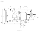
FIG. 2 is a configurative diagram of another conventional heat pump system for a vehicle; -
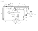
FIG. 3 is a configurative diagram of an air-conditioning mode of a heat pump system for a vehicle according to a preferred embodiment of the present invention; -
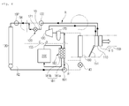
FIG. 4 is a configurative diagram of a first heating mode of a heat pump mode of the heat pump system for the vehicle according to the preferred embodiment of the present invention; -
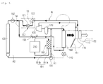
FIG. 5 is a configurative diagram of a dehumidification mode while carrying out the first heating mode of the heat pump mode of the heat pump system for the vehicle according to the preferred embodiment of the present invention; -
FIG. 6 is a configurative diagram of a second heating mode of the heat pump mode of the heat pump system for the vehicle according to the preferred embodiment of the present invention; -
FIG. 7 is a configurative diagram of a dehumidification mode while carrying out the second heating mode of the heat pump mode of the heat pump system for the vehicle according to the preferred embodiment of the present invention; -
FIG. 8 is a configurative diagram showing that an outlet of a dehumidification line ofFIG. 5 is connected to a bypass line of the second expansion means; and -
FIG. 9 is a perspective view of an expansion valve ofFIG. 8 . - Reference will be now made in detail to the preferred embodiment of the present invention with reference to the attached drawings.
- First, a heat pump system for a vehicle according to the present invention includes a
compressor 100, aninterior heat exchanger 110, first expansion means 120, anexterior heat exchanger 130, second expansion means 140, and anevaporator 160 which are connected on a refrigerant circulation line (R) in order, and is preferably applied to electric vehicles or hybrid vehicles. - Moreover, on the refrigerant circulation line (R), a bypass line (R1) bypassing the second expansion means 140 and the
evaporator 160, an auxiliary bypass line (R2) bypassing theexterior heat exchanger 130, and an expansion line (R3) on which the first expansion means 120 is mounted are respectively connected in parallel. - Furthermore, a first
direction changing valve 191 is mounted at a branching point of the bypass line (R1), a seconddirection changing valve 192 is mounted at a branching point of the auxiliary bypass line (R2), and a two-way valve 122 is mounted at a branching point of the expansion line (R3). - Therefore, in an air-conditioning mode, as shown in
FIG. 3 , the refrigerant discharged from thecompressor 100 circulates through theinterior heat exchanger 110, theexterior heat exchanger 130, the second expansion means 140, theevaporator 160, and thecompressor 100 in order. - In this instance, the
interior heat exchanger 110 serves as a condenser and theevaporator 160 serves as an evaporator. - Meanwhile, the
exterior heat exchanger 130 also serves as a condenser like theinterior heat exchanger 110. - In a heat pump mode (first heating mode), as shown in
FIG. 4 , the refrigerant discharged from thecompressor 100 circulates through theinterior heat exchanger 110, anorifice 121 of the first expansion means 120, theexterior heat exchanger 130, the bypass line (R1), and thecompressor 100 in order. - In this instance, the
interior heat exchanger 110 serves as a condenser and theexterior heat exchanger 130 serves as an evaporator. The refrigerant is not supplied to the second expansion means 140 and theevaporator 160. - In the meantime, when the interior of the vehicle is dehumidified in the heat pump mode, some of the refrigerant circulating in the refrigerant circulation line (R) is supplied to the
evaporator 160 through a dehumidification line (R4) which will be described later, such that the interior of the vehicle is dehumidified. - As described above, the heat pump system according to the preferred embodiment of the present invention can commonly use the refrigerant circulation line (R) because the air-conditioning mode and the heat pump mode have the same circulation direction of the refrigerant, prevent stagnation of refrigerant, and simplify the refrigerant circulation line (R).
- Hereinafter, components of the heat pump system for the vehicle according to the present invention will be described in detail.
- First, the
compressor 100 mounted on the refrigerant circulation line (R) inhales and compresses refrigerant while operating by receiving a driving force from an engine (an internal combustion engine) or a motor, and then, discharges the refrigerant in a gas phase of high-temperature and high-pressure. - The
compressor 100 inhales and compresses the refrigerant discharged from theevaporator 160 and supplies to theinterior heat exchanger 110 in the air-conditioning mode, and inhales and compresses the refrigerant discharged from theexterior heat exchanger 130 and passing through the bypass line (R1) and supplies to theinterior heat exchanger 110 in the heat pump mode. - Moreover, in the dehumidification mode of the heat pump mode, because refrigerants are simultaneously supplied to the
evaporator 160 through the bypass line (R1) and the dehumidification line (R4), thecompressor 100 inhales and compresses the refrigerants meeting after passing through the bypass line (R1) and theevaporator 160 and supplies the inhaled refrigerant to theinterior heat exchanger 110. - The
interior heat exchanger 110 is mounted inside the air-conditioning case 150 and connected with the refrigerant circulation line (R) of the outlet side of thecompressor 100 so as to heat-exchange air flowing inside the air-conditioning case 150 with the refrigerant discharged from thecompressor 100. - Furthermore, the
evaporator 160 is mounted inside the air-conditioning case 150 and connected with the refrigerant circulation line (R) of the inlet side of thecompressor 100 so as to heat-exchange the air flowing inside the air-conditioning case 150 with the refrigerant supplied to thecompressor 100. - The
interior heat exchanger 110 serves as a condenser all in the air-conditioning mode and the heat pump mode. - The
evaporator 160 serves as an evaporator in the air-conditioning mode, but is stopped in the first and second heating modes of the heat pump mode because refrigerant is not supplied and serves as an evaporator in the dehumidification mode because some of the refrigerant is supplied. - Moreover, the
interior heat exchanger 110 and theevaporator 160 are spaced apart from each other at a predetermined interval inside the air-conditioning case 150, and in this instance, are mounted in order from the upstream side of the air flow direction inside the air-conditioning case 150. - Therefore, in the air-conditioning mode that the
evaporator 160 serves as the evaporator, as shown inFIG. 3 , the refrigerant of low-temperature and low-pressure discharged from the second expansion means 140 is supplied to theevaporator 160, and in this instance, the air flowing inside the air-conditioning case 150 through the blower (not shown) is converted into cold air by exchanging heat with the refrigerant of low-temperature and low-pressure of theevaporator 160 while passing through theevaporator 160, and then, is discharged to the interior of the vehicle to thereby cool the interior of the vehicle. - In the heat pump mode (first heating mode) that the
interior heat exchanger 110 serves as a condenser, as shown inFIG. 4 , the refrigerant of high-temperature and high-pressure discharged from thecompressor 100 is supplied to theinterior heat exchanger 110, and in this instance, the air flowing inside the air-conditioning case 150 through the blower (not shown) is converted into warm air by exchanging heat with the refrigerant of high-temperature and high-pressure of theinterior heat exchanger 110 while passing through theinterior heat exchanger 110, and then, is discharged to the interior of the vehicle to thereby heat the interior of the vehicle. - In the meantime, it is preferable that the
evaporator 160 is larger than theinterior heat exchanger 110. - Moreover, a temperature-
adjustable door 151 for adjusting an amount of air bypassing theinterior heat exchanger 110 and an amount of air passing through theinterior heat exchanger 110 is mounted between theevaporator 160 and theinterior heat exchanger 110 inside the air-conditioning case 150. - The temperature-
adjustable door 151 adjusts the amount of the air bypassing theinterior heat exchanger 110 and the amount of the air passing through theinterior heat exchanger 110 to thereby properly control temperature of the air discharged from the air-conditioning case 150. - In this instance, in the air-conditioning mode, as shown in
FIG. 3 , when a front side passage of theinterior heat exchanger 110 is completely closed by the temperature-adjustable door 151, because the cold air passing through theevaporator 160 bypasses theinterior heat exchanger 110 and is supplied to the interior of the vehicle, the maximum heating is carried out. - In the heat pump mode (first heating mode), as shown in
FIG. 4 , when a passage bypassing theinterior heat exchanger 110 is completely closed by the temperature-adjustable door 151, because all of the air is converted into warm air while passing through theinterior heat exchanger 110 serving as the condenser and the warm air is supplied to the interior of the vehicle, the maximum heating is carried out. - Furthermore, the
exterior heat exchanger 130 is mounted outside the air-conditioning case 150 and connected with the refrigerant circulation line (R) so as to exchange heat between the refrigerant circulating the refrigerant circulation line (R) and the outdoor air. - Here, the
exterior heat exchanger 130 is mounted at the front side of an engine room of the vehicle to exchange heat between the refrigerant flowing inside theexterior heat exchanger 130 and the outdoor air. - In the air-conditioning mode, the
exterior heat exchanger 130 serves as a condenser like theinterior heat exchanger 110, and in this instance, the refrigerant of high-temperature and high-pressure flowing inside theexterior heat exchanger 130 is condensed while heat-exchanging with the outdoor air. In the heat pump mode (first heating mode), theexterior heat exchanger 130 serves as an evaporator differently from theinterior heat exchanger 110, and in this instance, refrigerant of low-temperature flowing inside theexterior heat exchanger 130 is evaporated while heat-exchanging with the outdoor air. - Moreover, the first expansion means 120 is mounted on the refrigerant circulation line (R) between the
interior heat exchanger 110 and theexterior heat exchanger 130 in order to selectively expand the refrigerant supplied to theexterior heat exchanger 130 according to the air-conditioning mode or the heat pump mode. - That is, the expansion line (R3) is mounted in parallel on the refrigerant circulation line (R) between the
interior heat exchanger 110 and theexterior heat exchanger 130, and in this instance, the first expansion means 120 has theorifice 121 mounted on the expansion line (R3). - Moreover, the two-
way valve 122 for changing a flow direction of the refrigerant so that the refrigerant passing theinterior heat exchanger 110 passes theorifice 121 through the expansion line (R3) or bypasses theorifice 121 according to the air-conditioning mode or the heat pump mode is mounted at the branching point of the expansion line (R3) and the refrigerant circulation line (R). - Therefore, in the air-conditioning mode, the refrigerant discharged from the
compressor 100 and passing through theinterior heat exchanger 110 bypasses theorifice 121 by the two-way valve 122 and is supplied to theexterior heat exchanger 130. In the heat pump mode (first heating mode), the refrigerant discharged from thecompressor 100 and passing through theinterior heat exchanger 110 is expanded while passing through theorifice 121 by the two-way valve 122 and is supplied to theexterior heat exchanger 130. - In the meantime, the
orifice 121 and the two-way valve 122 of the first expansion means 120 may be formed in a separate type or an integrated type. - Additionally, the bypass line (R1) is mounted in such a way as to connect the refrigerant circulation line (R) of the inlet side of the second expansion means 140 and the refrigerant circulation line (R) of the outlet side of the
evaporator 160 with each other, so that the refrigerant circulating through the refrigerant circulation line (R) selectively bypasses the second expansion means 140 and theevaporator 160. - As shown in the drawings, the bypass line (R1) is arranged in parallel with the second expansion means 140 and the
evaporator 160. That is, the inlet side of the bypass line (R1) is connected with the refrigerant circulation line (R) which connects theexterior heat exchanger 130 and the second expansion means 140 with each other, and the outlet side is connected with the refrigerant circulation line (R) which connects theevaporator 160 and thecompressor 100 with each other. - As a result, in the air-conditioning mode, the refrigerant passing through the
interior heat exchanger 130 flows toward the second expansion means 140 and theevaporator 160, but, in the heat pump mode (first heating mode), the refrigerant passing through theexterior heat exchanger 130 directly flows toward thecompressor 100 through the bypass line (R1) and bypasses the second expansion means 140 and theevaporator 160. - Here, the change in flow direction of the refrigerant according to the air-conditioning mode and the heat pump mode is achieved by the first
direction changing valve 191. - The first
direction changing valve 191 is mounted at a branching point of the bypass line (R1) and the refrigerant circulation line (R) so as to change the flow direction of the refrigerant in such a manner that the refrigerant passing through theexterior heat exchanger 130 flows toward the bypass line (R1) or the second expansion means 140 according to the air-conditioning mode or the heat pump mode. - In this instance, in the air-conditioning mode, the first
direction changing valve 191 changes the flow direction of the refrigerant in such a manner that the refrigerant discharged from thecompressor 100 and passing through theinterior heat exchanger 110 and theexterior heat exchanger 130 flows toward the second expansion means 140 and theevaporator 160, and in the heat pump mode (first heating mode), the firstdirection changing valve 191 changes the flow direction of the refrigerant in such a manner that the refrigerant discharged from thecompressor 100 and passing through theinterior heat exchanger 110, the first expansion means 120 and theexterior heat exchanger 130 flows toward the bypass line (R1). - In the meantime, it is preferable that the first
direction changing valve 191 is mounted at the branching point of the inlet side of the bypass line (R1) and uses a three-way valve. - Besides the first
direction changing valve 191, preferably, the second direction changing valve preferably uses the three-way valve. - A heat supply means 180 for supplying heat to the refrigerant flowing along the bypass line (R1) is mounted on the bypass line (R1).
- The heat supply means 180 has a water-cooled
type heat exchanger 181 including: a refrigerantheat exchange part 181a in which the refrigerant flowing in the bypass line (R1) flows so as to supply waste heat ofelectronic units 200 of the vehicle to the refrigerant flowing in the bypass line (R1); and a cooling waterheat exchange part 181b in which cooling water circulating theelectronic units 200 flows, the cooling waterheat exchange part 181b being disposed at one side of the refrigerantheat exchange part 181a. - Therefore, in the heat pump mode, the heat pump system can enhance heating performance by recovering a heat source from the waste heat of the
electronic units 200 of the vehicle. - In the meantime, there are motors, inverters and others as the
electronic units 200 of the vehicle. - Moreover, an
accumulator 170 is mounted on the refrigerant circulation line (R) of the inlet side of thecompressor 100. - The
accumulator 170 divides the refrigerant which is supplied to thecompressor 100 into the liquid-phase refrigerant and the gas-phase refrigerant and supplies only the gas-phase refrigerant to thecompressor 100. - Moreover, an
electric heater 115 for enhancing a heating efficiency is further mounted at the downstream side of theinterior heat exchanger 110 inside the air-conditioning case 150. - That is, the heat pump system can enhance heating performance by operating the
electric heater 115 at the beginning to start the vehicle as an auxiliary heat source, and can also operate theelectric heater 115 when the heat pump system is lacking in the heat source. - It is preferable that the
electric heater 115 is a PTC heater. - In addition, the auxiliary bypass line (R2) is mounted in parallel on the refrigerant circulation line (R) in such a manner that the refrigerant selectively passing the first expansion means 120 bypasses the
exterior heat exchanger 130. - In other words, the auxiliary bypass line (R2) is mounted to connect the refrigerant circulation lines (R) of the inlet and outlet sides of the
exterior heat exchanger 130 so that the refrigerant circulating through the refrigerant circulation line (R) bypasses theexterior heat exchanger 130. - Moreover, a second
direction changing valve 192 for changing a flow direction of the refrigerant is mounted in such a manner that the refrigerant circulating the refrigerant circulation line (R) selectively flows to the auxiliary bypass line (R2). - the second
direction changing valve 192 is mounted at the branching point of the auxiliary bypass line (R2) and the refrigerant circulation line (R) so as to change the flow direction of the refrigerant, such that the refrigerant flows toward theexterior heat exchanger 130 or the auxiliary bypass line (R2). - In this instance, when frosting is generated on the
exterior heat exchanger 130 or when the outdoor temperature is below zero, because theexterior heat exchanger 130 cannot smoothly inhale heat from the outdoor air, the seconddirection changing valve 192 makes the refrigerant circulating the refrigerant circulation line (R) bypass theexterior heat exchanger 130. - In the meantime, it is not necessary that the outdoor temperature is essentially 0°C. The heat pump system passes the refrigerant to the
exterior heat exchanger 130 only when heat-exchange efficiency between the outdoor air and the refrigerant flowing in theexterior heat exchanger 130 is good but bypasses the refrigerant when the heat-exchange efficiency is not good, thereby enhancing heating performance and efficiency. - Furthermore, in the case that frosting is generated on the
exterior heat exchanger 130, when refrigerant flows to the auxiliary bypass line (R2) and bypasses theexterior heat exchanger 130, frosting may be delayed or removed. - Additionally, the dehumidification lien (R4) is mounted on the refrigerant circulation line (R) for supplying some of the refrigerant circulating the refrigerant circulation line (R) to the
evaporator 160 so as to carry out dehumidification of the interior of the vehicle. - In this instance, in order to dehumidify the interior of the vehicle, because refrigerant of low temperature must be supplied to the
evaporator 160, the dehumidification line (R4) is connected with a section where the refrigerant of low temperature circulates in the refrigerant circulation line (R). - In more detail, the dehumidification line (R4) supplies some of the refrigerant passing the first expansion means 120 to the
evaporator 160. - In other words, the dehumidification line (R4) connects the refrigerant circulation line (R) of the outside side of the first expansion means 120 and the refrigerant circulation line (R) of the inlet side of the
evaporator 160 with each other. - In the drawings, the inlet of the dehumidification line (R4) is connected to the refrigerant circulation line (R) between the first expansion means 120 and the
exterior heat exchanger 130, such that some of the refrigerant flows to the dehumidification line (R4) and is supplied to theevaporator 160 before being introduced into theexterior heat exchanger 130 after passing the first expansion means 120. - Moreover, in the dehumidification mode, some of the refrigerant circulating the refrigerant circulation line (R) is supplied to the
evaporator 160 through the dehumidification line (R4), and in this instance, in order to secure heating performance, a flow amount of the refrigerant branched from the refrigerant circulation line (R) to the dehumidification line (R4) must be relative small. - Therefore, in order to make the flow amount of refrigerant branched to the dehumidification line (R4) become smaller than the flow amount of the refrigerant circulating the refrigerant circulation line (R), the following two methods may be used.
- First, a pipe diameter of the dehumidification line (R4) is smaller than a pipe diameter of the refrigerant circulation line (R) of the outlet side of the first expansion means 120, such that the flow amount of refrigerant branched to the dehumidification line (R4) becomes smaller.
- Second, a pipe of the dehumidification line (R4) is connected in such a way as to be branched above a pipe of the refrigerant circulation line (R), such that the flow amount of refrigerant branched to the dehumidification line (R4) becomes smaller.
- That is, if the pipe of the dehumidification line (R4) is connected in such a way as to be branched above the pipe of the refrigerant circulation line (R), when the refrigerant circulating the refrigerant circulation line (R) is branched toward the dehumidification line (R) located above, the flow amount of the refrigerant branched to the dehumidification line (R4) becomes smaller by gravity (self-weight).
- Moreover, the on-off
valve 195 which opens and closes the dehumidification line (R4) is mounted on the dehumidification line (R4), such that some of the refrigerant passing the first expansion means 120 can flow to the dehumidification line (R4) only in the dehumidification mode. - Furthermore, the heat pump system further includes a controller (not shown) for controlling the on-off
valve 195. - The controller opens the dehumidification line (R4) by opening the on-off
valve 195 only in the dehumidification mode, and closes the dehumidification line (R4) by closing the on-offvalve 195 not in the dehumidification mode. - Additionally, in the humidification mode, the controller turns off the on-off
valve 195 when frosting of theevaporator 160 is determined or frosting is sensed, and blocks the refrigerant supplied to theevaporator 160 through the dehumidification line (R4) so as to prevent frosting of theevaporator 160 in the dehumidification mode. - As described above, in the dehumidification mode, some of the refrigerant is supplied to the
evaporator 160 through the dehumidification line (R4) before the refrigerant is introduced into theexterior heat exchanger 130 after passing the first expansion means 120. In this case, because the refrigerant flowing in the dehumidification line (R4) is the refrigerant before being introduced into theexterior heat exchanger 130, in other words, because the refrigerant flowing in the dehumidification line (R4) does not yet heat-exchange with cold outdoor air in theexterior heat exchanger 130, pressure of the refrigerant flowing in the dehumidification line (R4) is higher than pressure of theevaporator 160. - That is, referring to
FIG. 5 , based on the on-offvalve 195 of the dehumidification line (R4), because pressure of the C side is higher than pressure of the D side (evaporator side), in the dehumidification mode, when the on-offvalve 195 is opened, some of the refrigerant passing the first expansion means 120 smoothly flows to theevaporator 160 of a lower pressure through the dehumidification line (R4), and hence, the heat pump system can smoothly carry out dehumidification of the interior of the vehicle. - In addition, as shown in
FIGS. 3 to 7 , the outlet of the dehumidification line (R4) is connected with the refrigerant circulation line (R) of the inlet side of theevaporator 160, or as shown inFIG. 8 , is connected with the second expansion means 140. - In
FIGS. 3 to 7 , the outlet of the dehumidification line (R4) is connected with the refrigerant circulation line (R) between the second expansion means 140 and theevaporator 160. Therefore, the refrigerant passing the dehumidification line (R4) is directly introduced into theevaporator 160. - In
FIG. 8 , the outlet of the dehumidification line (R4) is connected with the second expansion means 140, but in this instance, the refrigerant passing the dehumidification line (R4) is not expanded in the second expansion means 140 but is introduced into theevaporator 160. - That is, as shown in
FIG. 9 , the second expansion means 140 includes anexpansion valve 140a having anexpansion flow channel 144 for expanding the refrigerant and abypass flow channel 147 for making the refrigerant bypass theexpansion flow channel 144. - In this instance, the outlet of the dehumidification line (R4) is connected with the
bypass flow channel 147 of theexpansion valve 140a, and the refrigerant passing the dehumidification line (R4) bypasses theexpansion flow channel 144 through thebypass flow channel 147 and is supplied to theevaporator 160. - Referring to
FIG. 9 , theexpansion valve 140a of the second expansion means 140 will be described in brief. Theexpansion valve 140a includes: amain body 141 having afirst flow channel 142 which has theexpansion flow channel 144 for expanding the refrigerant supplied to theevaporator 160 and asecond flow channel 143 in which the refrigerant discharged from theevaporator 160 flows; avalve body 145 mounted inside themain body 141 for regulating a flow amount of the refrigerant passing theexpansion flow channel 144 by controlling the degree of opening of theexpansion flow channel 144; and arod 146 elevatably mounted inside themain body 141 for lifting thevalve body 145 according to a temperature change of the refrigerant of the outlet side of theevaporator 160 which flows in thesecond flow channel 143. - Here, the
main body 141 of theexpansion valve 140a includes: aninlet 142a for introducing refrigerant to theexpansion flow channel 144; and anoutlet 142b for discharging out the refrigerant passing theexpansion flow channel 144. - Inside the
main body 141, theinlet 142a and theoutlet 142b are arranged at an angle of 90 degrees, and in this instance, they are spaced apart from each other at a predetermined interval in a perpendicular direction, and theexpansion flow channel 144 is formed between theinlet 142a and theoutlet 142b. - Moreover, a diaphragm (not shown) which is displaced according to the temperature change of the refrigerant flowing in the
second flow channel 143 is mounted at the upper end of themain body 141. Therefore, thevalve body 145 is operated while therod 146 is ascending and descending according to the displacement of the diaphragm. - Furthermore, the
bypass flow channel 147 to which the dehumidification line (R4) is connected is formed in themain body 141, and is communicated with theoutlet 142b of thefirst flow channel 142 which is the downstream side of theexpansion flow channel 144 in the refrigerant flow direction. - In this instance, the
inlet 147a of thebypass flow channel 147 is arranged collinearly with theoutlet 142b of thefirst flow channel 142. - In other words, the
inlet 147a of thebypass flow channel 147 and theoutlet 142b of thefirst flow channel 142 are formed in a straight line. - Therefore, the refrigerant passing the dehumidification line (R4) bypasses the
expansion flow channel 144 of the second expansion means 140 through thebypass flow channel 147 and is directly supplied to theevaporator 160. - Moreover, because the
bypass flow channel 147 is formed in a straight line with theoutlet 142b of thefirst flow channel 142, the heat pump system can minimize a pressure loss and a flow noise of the refrigerant. - In the meantime, because the outlet of the dehumidification line (R4) is inserted into the
bypass flow channel 147 of the second expansion means 140, the dehumidification line (R4) can be simply assembled, and the number of components and weight of the system can be reduced due to the simple connection structure. - Hereinafter, the action of the heat pump system for the vehicle according to the preferred embodiment of the present invention will be described.
- In the air-conditioning mode (cooling mode), as shown in
FIG. 3 , the auxiliary bypass line (R2) is closed by the seconddirection changing valve 192, the bypass line (R1) is also closed by the firstdirection changing valve 191, and the two-way valve 122 closes theorifice 121. - Moreover, the cooling water circulating through the
electronic units 200 is not supplied to the water coolingtype heat exchanger 181 of theheat supplying means 180. - Meanwhile, in order to achieve the maximum cooling, the temperature
adjustable door 151 inside the air-conditioning case 150 closes the passage passing through theinterior heat exchanger 110, so that the air blown into the air-conditioning case 150 by the blower is cooled while passing through theevaporator 160 and is supplied to the interior of the vehicle by bypassing theinterior heat exchanger 110 to thereby cool the interior of the vehicle. - Continuously, a refrigerant circulation process will be described.
- The gas-phase refrigerant of high-temperature and high-pressure discharged after being compressed in the
compressor 100 is supplied to theinterior heat exchanger 110 mounted inside the air-conditioning case 150. - As shown in
FIG. 3 , the refrigerant supplied to theinterior heat exchanger 110 directly flows to theexterior heat exchanger 130 without heat-exchanging with the air because the temperatureadjustable door 151 closes the passage of theinterior heat exchanger 110. - The refrigerant flowing to the
exterior heat exchanger 130 is condensed while heat-exchanging with the outdoor air, and thereby, the gas-phase refrigerant is converted into the liquid-phase refrigerant. - In the meantime, all of the
interior heat exchanger 110 and theexterior heat exchanger 130 serve as the condensers, but the refrigerant is mainly condensed in theexterior heat exchanger 130 which heat-exchanges with the outdoor air. - Continuously, the refrigerant passing through the
exterior heat exchanger 130 is decompressed and expanded while passing through the second expansion means 140 to thereby become a liquid-phase refrigerant of low-temperature and low-pressure, and then, is introduced into theevaporator 160. - The refrigerant introduced into the
evaporator 160 is evaporated by heat-exchanging with the air blown into the air-conditioning case 150 by the blower, and at the same time, cools the air due to a heat absorption by an evaporative latent heat of the refrigerant, and then, the cooled air is supplied to the interior of the vehicle to cool the interior. - After that, the refrigerant discharged from the
evaporator 160 is introduced into thecompressor 100 and recirculates the above cycle. - The first heating mode of the heat pump mode is operated under the condition that there is no frosting on the
exterior heat exchanger 130 or that the outdoor temperature is above zero. As shown inFIG. 4 , the auxiliary bypass line (R2) is opened by the seconddirection changing valve 192 and the bypass line (R1) is opened by the firstdirection changing valve 191, such that the refrigerant is not supplied to the second expansion means 140 and theevaporator 160. - Moreover, the
orifice 121 is opened by the two-way valve 122. - Meanwhile, the cooling water heated by the
electronic units 200 of the vehicle is supplied to the cooling water heat-exchangingpart 181b of the water coolingtype heat exchanger 181 of theheat supplying means 180. - Furthermore, in the first heating mode, the temperature
adjustable door 151 inside the air-conditioning case 150 closes the passage bypassing theinterior heat exchanger 110, so that the air blown into the air-conditioning case 150 by the blower is changed into warm air while passing through theinterior heat exchanger 110 after passing through theevaporator 160 which is stopped in operation, and then is supplied to the interior of the vehicle to heat the interior of the vehicle. - Continuously, a refrigerant circulation process will be described.
- The gas-phase refrigerant of high-temperature and high-pressure discharged after being compressed in the
compressor 100 is introduced into theinterior heat exchanger 110 mounted inside the air-conditioning case 150. - The gas-phase refrigerant of high-temperature and high-pressure introduced into the
interior heat exchanger 110 is condensed while heat-exchanging with the air blown into the air-conditioning case 150 by the blower, and in this instance, the air passing through theinterior heat exchanger 110 is converted into warm air and supplied to the interior of the vehicle to thereby heat the interior of the vehicle. - Continuously the refrigerant discharged from the
interior heat exchanger 110 is decompressed and expanded while passing through theorifice 121 by the two-way valve 122 to thereby become a liquid-phase refrigerant of low-temperature and low-pressure, and then, is supplied to theexterior heat exchanger 130 which serves as an evaporator. - The refrigerant supplied to the
exterior heat exchanger 130 is evaporated while heat-exchanging with the indoor air and passes the bypass line (R1) by the firstdirection changing valve 191. In this instance, the refrigerant passing the bypass line (R1) heat-exchanges with the cooling water passing through the cooling water heat-exchangingpart 181b while passing through the refrigerant heat-exchangingpart 181a of the water coolingtype heat exchanger 181 so as to recover the waste heat of theelectronic units 200 of the vehicle, and then, is introduced into thecompressor 100 to recirculate the above cycle. - The dehumidification mode of the first heating mode of the heat pump mode is operated only in the case that dehumidification of the interior of the vehicle is needed while the system is operated in the first heating mode of
FIG. 4 . - Therefore, only different parts from the first heating mode of
FIG. 4 will be described. - In the dehumidification mode, the dehumidification line (R4) is additionally opened by the on-off
valve 195 in the state where the first heating mode is operated. - Moreover, the temperature-adjusting
door 151 inside the air-conditioning case 150 closes a passageway bypassing theinterior heat exchanger 110. Therefore, air blown into the air-conditioning case 150 by a blower is cooled while passing theevaporator 160, and then, is changed into warm air while passing theinterior heat exchanger 110 and is supplied to the interior of the vehicle, such that the heat pump system can heat the interior of the vehicle. - In this instance, because the amount of the refrigerant supplied to the
evaporator 160 is small and an air cooling performance is low, it minimizes a change of indoor temperature, such that the heat pump system can smoothly dehumidify the air passing theevaporator 160. - Continuously, a refrigerant circulation process will be described.
- Some of the refrigerant passing the
compressor 100, theinterior heat exchanger 110, and theorifice 121 of the first expansion means 120 passes theexterior heat exchanger 130, and some of the refrigerant passes the dehumidification line (R4). - The refrigerant passing the
exterior heat exchanger 130 is evaporated while heat-exchanging with the outdoor air, and then, passes the bypass line (R1) by the firstdirection changing valve 191. In this instance, the refrigerant passing the bypass line (R1) heat-exchanges with cooling water passing the cooling waterheat exchange part 181b while passing the refrigerantheat exchange part 181a of the water-coolingtype heat exchanger 181 so as to be evaporated while recovering waste heat of theelectronic units 200 of the vehicle. - The refrigerant passing the dehumidification line (R4) is supplied to the
evaporator 160, and is evaporated while heat-exchanging with the air flowing inside the air-conditioning case 150. - In the above process, the air passing the
evaporator 160 is dehumidified, and the dehumidified air is changed into warm air while passing theinterior heat exchanger 110, and then, is supplied to the interior of the vehicle so as to carry out dehumidification. - After that, the refrigerants respectively passing the water-cooling
type heat exchanger 181 and theevaporator 160 meet together and are introduced into thecompressor 100, and then, the above-mentioned cycle is re-circulated. - The second heating mode of the heat pump mode is operated under the condition that frosting is generated on the
exterior heat exchanger 130 or that the outdoor temperature is below zero. As shown inFIG. 6 , the auxiliary bypass line (R2) is opened by the seconddirection changing valve 192 and the bypass line (R1) is opened by the firstdirection changing valve 191. - Moreover, the dehumidification lien (R4) is closed by the on-off
valve 195, theorifice 121 is opened by the two-way valve 122, and the mode is converted into an indoor air inflow mode for introducing the indoor air into the air-conditioning case 150. - Meanwhile, the cooling water heated by the
electronic units 200 of the vehicle is supplied to the cooling water heat-exchangingpart 181b of the water coolingtype heat exchanger 181 of theheat supplying means 180. - Furthermore, in the second heating mode, the temperature
adjustable door 151 inside the air-conditioning case 150 closes the passage bypassing theinterior heat exchanger 110, so that the air blown into the air-conditioning case 150 by the blower is changed into warm air while passing through theinterior heat exchanger 110 after passing through theevaporator 160 which is stopped in operation, and then is supplied to the interior of the vehicle to heat the interior of the vehicle. - Continuously, a refrigerant circulation process will be described.
- The gas-phase refrigerant of high-temperature and high-pressure discharged after being compressed in the
compressor 100 is introduced into theinterior heat exchanger 110 mounted inside the air-conditioning case 150. - The gas-phase refrigerant of high-temperature and high-pressure introduced into the
interior heat exchanger 110 is condensed while heat-exchanging with the air blown into the air-conditioning case 150 by the blower, and in this instance, the air passing through theinterior heat exchanger 110 is converted into warm air and supplied to the interior of the vehicle to thereby heat the interior of the vehicle. - Continuously the refrigerant discharged from the
interior heat exchanger 110 is decompressed and expanded while passing through theorifice 121 by the two-way valve 122 to thereby become a liquid-phase refrigerant of low-temperature and low-pressure. After that, the refrigerant flows to the auxiliary bypass line (R2) and bypasses theexterior heat exchanger 130. - After that, the refrigerant passing through the auxiliary bypass line (R2) passes the bypass line (R1) by the first
direction changing valve 191. In this instance, the refrigerant passing the bypass line (R1) heat-exchanges with the cooling water passing through the cooling water heat-exchangingpart 181b while passing through the refrigerant heat-exchangingpart 181a of the water coolingtype heat exchanger 181 so as to recover the waste heat of theelectronic units 200 of the vehicle, and then, is introduced into thecompressor 100 to recirculate the above cycle. - The dehumidification mode of the second heating mode of the heat pump mode is operated only in the case that dehumidification of the interior of the vehicle is needed while the system is operated in the second heating mode of
FIG. 6 . - Therefore, only different parts from the second heating mode of
FIG. 6 will be described. - In the dehumidification mode, the dehumidification line (R4) is additionally opened by the on-off
valve 195 in the state where the second heating mode is operated. - Moreover, the temperature-adjusting
door 151 inside the air-conditioning case 150 closes a passageway bypassing theinterior heat exchanger 110. Therefore, air blown into the air-conditioning case 150 by a blower is cooled while passing theevaporator 160, and then, is changed into warm air while passing theinterior heat exchanger 110 and is supplied to the interior of the vehicle, such that the heat pump system can heat the interior of the vehicle. - In this instance, because the amount of the refrigerant supplied to the
evaporator 160 is small and an air cooling performance is low, it minimizes a change of indoor temperature, such that the heat pump system can smoothly dehumidify the air passing theevaporator 160. - Continuously, a refrigerant circulation process will be described.
- Some of the refrigerant passing the
compressor 100, theinterior heat exchanger 110, and theorifice 121 of the first expansion means 120 bypasses theexterior heat exchanger 130 through the auxiliary bypass line (R2), and some of the refrigerant passes the dehumidification line (R4). - The refrigerant passing the auxiliary bypass line (R2) passes the bypass line (R1) by the first
direction changing valve 191. In this instance, some of the refrigerant passing the bypass line (R1) heat-exchanges with cooling water passing the cooling waterheat exchange part 181b while passing the refrigerantheat exchange part 181a of the water-coolingtype heat exchanger 181 so as to be evaporated while recovering waste heat of theelectronic units 200 of the vehicle. - The refrigerant passing the dehumidification line (R4) is supplied to the
evaporator 160, and is evaporated while heat-exchanging with the air flowing inside the air-conditioning case 150. - In the above process, the air passing the
evaporator 160 is dehumidified, and the dehumidified air is changed into warm air while passing theinterior heat exchanger 110, and then, is supplied to the interior of the vehicle so as to carry out dehumidification. - After that, the refrigerants respectively passing the water-cooling
type heat exchanger 181 and theevaporator 160 meet together and are introduced into thecompressor 100, and then, the above-mentioned cycle is re-circulated.
Claims (10)
- In a heat pump system for a vehicle, which includes: a compressor (100) mounted on a refrigerant circulation line (R) for compressing and discharging refrigerant; an interior heat exchanger (110) mounted inside an air-conditioning case (150) for exchanging heat between the air inside the air-conditioning case (150) and the refrigerant discharged from the compressor (100); an evaporator (160) mounted inside the air-conditioning case (150) for exchanging heat between the air inside the air-conditioning case (150) and the refrigerant supplied to the compressor (100); an exterior heat exchanger (130) mounted outside the air-conditioning case (150) for exchanging heat between the refrigerant circulating through the refrigerant circulation line (R) and the outdoor air; first expansion means (120) mounted on the refrigerant circulation line (R) located between the interior heat exchanger (110) and the exterior heat exchanger (130) for expanding refrigerant; second expansion means mounted on the refrigerant circulation line (R) of an inlet side of the evaporator (160) for expanding refrigerant; and a bypass line (R1) mounted in such a way as to connect the refrigerant circulation line (R) of an inlet side of the second expansion means (140) and the refrigerant circulation line (R) of an outlet side of the evaporator (160), such that refrigerant bypasses the second expansion means (140) and the evaporator (160) in a heat pump mode,
the improvement characterized in that the heat pump system comprises a dehumidification line (R4) for supplying some of the refrigerant circulating the refrigerant circulation line (R) to the evaporator (160) is mounted on the refrigerant circulation line (R) so as to dehumidify the interior of the vehicle in the heat pump mode,
wherein the dehumidification line (R4) supplies some of the refrigerant passing the first expansion means (120) to the evaporator (160). - The heat pump system according to claim 1, wherein the dehumidification line (R4) connects the refrigerant circulation line (R) of the outlet side of the first expansion means (120) and the refrigerant circulation line (R) of the inlet side of the evaporator (160) with each other.
- The heat pump system according to claim 1, wherein the second expansion means (140) comprises: an expansion valve (140a) having an expansion flow channel (144) for expanding refrigerant and a bypass flow channel (147) for making the refrigerant bypass the expansion flow channel (144), and
wherein the dehumidification line (R4) connects the refrigerant circulation line (R) of the outlet side of the first expansion means (120) and the bypass flow channel (147) of the expansion valve (140a) with each other, such that the refrigerant passing the dehumidification line (R4) bypasses the expansion flow channel (144) through the bypass flow channel (147) and is supplied to the evaporator (160). - The heat pump system according to claim 3, wherein the expansion valve (140a) comprises: an inlet (142a) for introducing refrigerant into the expansion flow channel (144); and an outlet (142b) for discharging the refrigerant passing the expansion flow channel (144), and
wherein an inlet (147a) of the bypass flow channel (147) to which the dehumidification line (R4) is connected is arranged collinearly with the outlet (142b). - The heat pump system according to claim 1, wherein an on-off valve (195) for opening and closing the dehumidification line (R4) is mounted on the dehumidification line (R4) such that some of the refrigerant passing the first expansion means (120) flows to the dehumidification line (R4) only in the dehumidification mode.
- The heat pump system according to claim 5, further comprising:a controller for controlling the on-off valve (195), and the controller controls an on-off function of the on-off valve (195) in the dehumidification mode when frosting of the evaporator (160) is determined or sensed, so as to prevent the refrigerant from being supplied to the evaporator (160) through the dehumidification line (R4).
- The heat pump system according to claim 1, wherein a pipe diameter of the dehumidification line (R4) is smaller than a pipe diameter of the refrigerant circulation line (R) of the outlet side of the first expansion means (120).
- The heat pump system according to claim 1, wherein a pipe of the dehumidification line (R4) is connected in such a way as to be branched above a pipe of the refrigerant circulation line (R) of the outlet side of the first expansion means (120).
- The heat pump system according to claim 1, wherein heat supply means (180) is mounted on the bypass line (R1) in order to supply waste heat of electronic units (200) of the vehicle to the refrigerant flowing along the bypass line (R1).
- The heat pump system according to claim 1, wherein an auxiliary bypass line (R2) is mounted on the refrigerant circulation line (R) in order to make the refrigerant passing the first expansion means (120) bypass the exterior heat exchanger (130) when frosting is generated on the exterior heat exchanger (130).
Priority Applications (1)
| Application Number | Priority Date | Filing Date | Title |
|---|---|---|---|
| EP14161524.5A EP2923866B1 (en) | 2014-03-25 | 2014-03-25 | Heat pump system for vehicle |
Applications Claiming Priority (1)
| Application Number | Priority Date | Filing Date | Title |
|---|---|---|---|
| EP14161524.5A EP2923866B1 (en) | 2014-03-25 | 2014-03-25 | Heat pump system for vehicle |
Publications (2)
| Publication Number | Publication Date |
|---|---|
| EP2923866A1 true EP2923866A1 (en) | 2015-09-30 |
| EP2923866B1 EP2923866B1 (en) | 2018-05-02 |
Family
ID=50345945
Family Applications (1)
| Application Number | Title | Priority Date | Filing Date |
|---|---|---|---|
| EP14161524.5A Active EP2923866B1 (en) | 2014-03-25 | 2014-03-25 | Heat pump system for vehicle |
Country Status (1)
| Country | Link |
|---|---|
| EP (1) | EP2923866B1 (en) |
Cited By (4)
| Publication number | Priority date | Publication date | Assignee | Title |
|---|---|---|---|---|
| CN106904058A (en) * | 2017-03-10 | 2017-06-30 | 安徽江淮汽车集团股份有限公司 | Control method for electronic expansion valve and device in heat pump type air conditioning system |
| US20170361677A1 (en) * | 2016-06-20 | 2017-12-21 | Hyundai Motor Company | Heat pump system for vehicle |
| US20190135075A1 (en) * | 2016-07-11 | 2019-05-09 | Hanon Systems | Heat pump system for vehicle |
| US20190351733A1 (en) * | 2016-01-13 | 2019-11-21 | Hanon Systems | Air conditioner for vehicle |
Citations (4)
| Publication number | Priority date | Publication date | Assignee | Title |
|---|---|---|---|---|
| US20100326127A1 (en) * | 2009-06-26 | 2010-12-30 | Denso Corporation | Air conditioner for vehicle with heat pump cycle |
| KR20120103054A (en) | 2011-03-09 | 2012-09-19 | 한라공조주식회사 | Heat pump system for vehicle |
| WO2012137468A1 (en) * | 2011-04-08 | 2012-10-11 | 株式会社テージーケー | Vehicle heating and cooling apparatus |
| EP2636548A1 (en) * | 2012-03-05 | 2013-09-11 | Halla Visteon Climate Control Corp. | Heat pump system for vehicle |
-
2014
- 2014-03-25 EP EP14161524.5A patent/EP2923866B1/en active Active
Patent Citations (4)
| Publication number | Priority date | Publication date | Assignee | Title |
|---|---|---|---|---|
| US20100326127A1 (en) * | 2009-06-26 | 2010-12-30 | Denso Corporation | Air conditioner for vehicle with heat pump cycle |
| KR20120103054A (en) | 2011-03-09 | 2012-09-19 | 한라공조주식회사 | Heat pump system for vehicle |
| WO2012137468A1 (en) * | 2011-04-08 | 2012-10-11 | 株式会社テージーケー | Vehicle heating and cooling apparatus |
| EP2636548A1 (en) * | 2012-03-05 | 2013-09-11 | Halla Visteon Climate Control Corp. | Heat pump system for vehicle |
Cited By (6)
| Publication number | Priority date | Publication date | Assignee | Title |
|---|---|---|---|---|
| US20190351733A1 (en) * | 2016-01-13 | 2019-11-21 | Hanon Systems | Air conditioner for vehicle |
| US10821801B2 (en) * | 2016-01-13 | 2020-11-03 | Hanon Systems | Air conditioner for vehicle |
| US20170361677A1 (en) * | 2016-06-20 | 2017-12-21 | Hyundai Motor Company | Heat pump system for vehicle |
| US20190135075A1 (en) * | 2016-07-11 | 2019-05-09 | Hanon Systems | Heat pump system for vehicle |
| CN106904058A (en) * | 2017-03-10 | 2017-06-30 | 安徽江淮汽车集团股份有限公司 | Control method for electronic expansion valve and device in heat pump type air conditioning system |
| CN106904058B (en) * | 2017-03-10 | 2019-12-31 | 安徽江淮汽车集团股份有限公司 | Control method and device for electronic expansion valve in heat pump air conditioning system |
Also Published As
| Publication number | Publication date |
|---|---|
| EP2923866B1 (en) | 2018-05-02 |
Similar Documents
| Publication | Publication Date | Title |
|---|---|---|
| US9643473B2 (en) | Heat pump system for vehicles | |
| US10744850B2 (en) | Heat pump system for vehicle | |
| US11034207B2 (en) | Heat pump system for vehicle | |
| US10752092B2 (en) | Vehicular heat pump system | |
| EP2636548B1 (en) | Heat pump system for vehicle | |
| US8948966B2 (en) | Heat pump system for vehicle and method of controlling the same | |
| EP3081408B1 (en) | Automotive heat pump system | |
| CN104515335B (en) | Vehicle heat pump | |
| US9855821B2 (en) | Heat pump system for vehicle | |
| US10457115B2 (en) | Air conditioning system for vehicle | |
| US20190135075A1 (en) | Heat pump system for vehicle | |
| KR101669826B1 (en) | Heat pump system for vehicle | |
| EP2900497B1 (en) | Heat pump system for vehicle | |
| US20150217625A1 (en) | Heat pump system for vehicle | |
| KR101511508B1 (en) | Heat pump system for vehicle | |
| KR102111323B1 (en) | Heat pump system for vehicle | |
| CN104949385B (en) | vehicular heat pump system | |
| KR102200390B1 (en) | Automotive air conditioning system | |
| US20190210427A1 (en) | Heat pump system for vehicle | |
| EP2923866B1 (en) | Heat pump system for vehicle | |
| KR20130101254A (en) | Heat pump system for vehicle | |
| KR101544877B1 (en) | Heat pump system for vehicle | |
| KR101510116B1 (en) | Heat pump system for vehicle | |
| KR20130101263A (en) | Heat pump system for vehicle |
Legal Events
| Date | Code | Title | Description |
|---|---|---|---|
| PUAI | Public reference made under article 153(3) epc to a published international application that has entered the european phase |
Free format text: ORIGINAL CODE: 0009012 |
|
| AK | Designated contracting states |
Kind code of ref document: A1 Designated state(s): AL AT BE BG CH CY CZ DE DK EE ES FI FR GB GR HR HU IE IS IT LI LT LU LV MC MK MT NL NO PL PT RO RS SE SI SK SM TR |
|
| AX | Request for extension of the european patent |
Extension state: BA ME |
|
| RAP1 | Party data changed (applicant data changed or rights of an application transferred) |
Owner name: HANON SYSTEMS |
|
| 17P | Request for examination filed |
Effective date: 20160330 |
|
| RBV | Designated contracting states (corrected) |
Designated state(s): AL AT BE BG CH CY CZ DE DK EE ES FI FR GB GR HR HU IE IS IT LI LT LU LV MC MK MT NL NO PL PT RO RS SE SI SK SM TR |
|
| GRAP | Despatch of communication of intention to grant a patent |
Free format text: ORIGINAL CODE: EPIDOSNIGR1 |
|
| STAA | Information on the status of an ep patent application or granted ep patent |
Free format text: STATUS: GRANT OF PATENT IS INTENDED |
|
| RIC1 | Information provided on ipc code assigned before grant |
Ipc: B60H 1/00 20060101AFI20180104BHEP Ipc: F25B 6/04 20060101ALI20180104BHEP Ipc: F25B 41/06 20060101ALI20180104BHEP Ipc: F25B 5/04 20060101ALI20180104BHEP |
|
| INTG | Intention to grant announced |
Effective date: 20180129 |
|
| GRAS | Grant fee paid |
Free format text: ORIGINAL CODE: EPIDOSNIGR3 |
|
| GRAA | (expected) grant |
Free format text: ORIGINAL CODE: 0009210 |
|
| STAA | Information on the status of an ep patent application or granted ep patent |
Free format text: STATUS: THE PATENT HAS BEEN GRANTED |
|
| AK | Designated contracting states |
Kind code of ref document: B1 Designated state(s): AL AT BE BG CH CY CZ DE DK EE ES FI FR GB GR HR HU IE IS IT LI LT LU LV MC MK MT NL NO PL PT RO RS SE SI SK SM TR |
|
| REG | Reference to a national code |
Ref country code: GB Ref legal event code: FG4D |
|
| REG | Reference to a national code |
Ref country code: CH Ref legal event code: EP Ref country code: AT Ref legal event code: REF Ref document number: 994816 Country of ref document: AT Kind code of ref document: T Effective date: 20180515 |
|
| REG | Reference to a national code |
Ref country code: DE Ref legal event code: R096 Ref document number: 602014024745 Country of ref document: DE Ref country code: IE Ref legal event code: FG4D |
|
| REG | Reference to a national code |
Ref country code: NL Ref legal event code: MP Effective date: 20180502 |
|
| REG | Reference to a national code |
Ref country code: LT Ref legal event code: MG4D |
|
| PG25 | Lapsed in a contracting state [announced via postgrant information from national office to epo] |
Ref country code: FI Free format text: LAPSE BECAUSE OF FAILURE TO SUBMIT A TRANSLATION OF THE DESCRIPTION OR TO PAY THE FEE WITHIN THE PRESCRIBED TIME-LIMIT Effective date: 20180502 Ref country code: BG Free format text: LAPSE BECAUSE OF FAILURE TO SUBMIT A TRANSLATION OF THE DESCRIPTION OR TO PAY THE FEE WITHIN THE PRESCRIBED TIME-LIMIT Effective date: 20180802 Ref country code: NO Free format text: LAPSE BECAUSE OF FAILURE TO SUBMIT A TRANSLATION OF THE DESCRIPTION OR TO PAY THE FEE WITHIN THE PRESCRIBED TIME-LIMIT Effective date: 20180802 Ref country code: SE Free format text: LAPSE BECAUSE OF FAILURE TO SUBMIT A TRANSLATION OF THE DESCRIPTION OR TO PAY THE FEE WITHIN THE PRESCRIBED TIME-LIMIT Effective date: 20180502 Ref country code: ES Free format text: LAPSE BECAUSE OF FAILURE TO SUBMIT A TRANSLATION OF THE DESCRIPTION OR TO PAY THE FEE WITHIN THE PRESCRIBED TIME-LIMIT Effective date: 20180502 Ref country code: LT Free format text: LAPSE BECAUSE OF FAILURE TO SUBMIT A TRANSLATION OF THE DESCRIPTION OR TO PAY THE FEE WITHIN THE PRESCRIBED TIME-LIMIT Effective date: 20180502 |
|
| PG25 | Lapsed in a contracting state [announced via postgrant information from national office to epo] |
Ref country code: NL Free format text: LAPSE BECAUSE OF FAILURE TO SUBMIT A TRANSLATION OF THE DESCRIPTION OR TO PAY THE FEE WITHIN THE PRESCRIBED TIME-LIMIT Effective date: 20180502 Ref country code: RS Free format text: LAPSE BECAUSE OF FAILURE TO SUBMIT A TRANSLATION OF THE DESCRIPTION OR TO PAY THE FEE WITHIN THE PRESCRIBED TIME-LIMIT Effective date: 20180502 Ref country code: GR Free format text: LAPSE BECAUSE OF FAILURE TO SUBMIT A TRANSLATION OF THE DESCRIPTION OR TO PAY THE FEE WITHIN THE PRESCRIBED TIME-LIMIT Effective date: 20180803 Ref country code: HR Free format text: LAPSE BECAUSE OF FAILURE TO SUBMIT A TRANSLATION OF THE DESCRIPTION OR TO PAY THE FEE WITHIN THE PRESCRIBED TIME-LIMIT Effective date: 20180502 Ref country code: LV Free format text: LAPSE BECAUSE OF FAILURE TO SUBMIT A TRANSLATION OF THE DESCRIPTION OR TO PAY THE FEE WITHIN THE PRESCRIBED TIME-LIMIT Effective date: 20180502 |
|
| REG | Reference to a national code |
Ref country code: AT Ref legal event code: MK05 Ref document number: 994816 Country of ref document: AT Kind code of ref document: T Effective date: 20180502 |
|
| PG25 | Lapsed in a contracting state [announced via postgrant information from national office to epo] |
Ref country code: CZ Free format text: LAPSE BECAUSE OF FAILURE TO SUBMIT A TRANSLATION OF THE DESCRIPTION OR TO PAY THE FEE WITHIN THE PRESCRIBED TIME-LIMIT Effective date: 20180502 Ref country code: DK Free format text: LAPSE BECAUSE OF FAILURE TO SUBMIT A TRANSLATION OF THE DESCRIPTION OR TO PAY THE FEE WITHIN THE PRESCRIBED TIME-LIMIT Effective date: 20180502 Ref country code: RO Free format text: LAPSE BECAUSE OF FAILURE TO SUBMIT A TRANSLATION OF THE DESCRIPTION OR TO PAY THE FEE WITHIN THE PRESCRIBED TIME-LIMIT Effective date: 20180502 Ref country code: EE Free format text: LAPSE BECAUSE OF FAILURE TO SUBMIT A TRANSLATION OF THE DESCRIPTION OR TO PAY THE FEE WITHIN THE PRESCRIBED TIME-LIMIT Effective date: 20180502 Ref country code: AT Free format text: LAPSE BECAUSE OF FAILURE TO SUBMIT A TRANSLATION OF THE DESCRIPTION OR TO PAY THE FEE WITHIN THE PRESCRIBED TIME-LIMIT Effective date: 20180502 Ref country code: SK Free format text: LAPSE BECAUSE OF FAILURE TO SUBMIT A TRANSLATION OF THE DESCRIPTION OR TO PAY THE FEE WITHIN THE PRESCRIBED TIME-LIMIT Effective date: 20180502 Ref country code: PL Free format text: LAPSE BECAUSE OF FAILURE TO SUBMIT A TRANSLATION OF THE DESCRIPTION OR TO PAY THE FEE WITHIN THE PRESCRIBED TIME-LIMIT Effective date: 20180502 |
|
| REG | Reference to a national code |
Ref country code: DE Ref legal event code: R097 Ref document number: 602014024745 Country of ref document: DE |
|
| PG25 | Lapsed in a contracting state [announced via postgrant information from national office to epo] |
Ref country code: SM Free format text: LAPSE BECAUSE OF FAILURE TO SUBMIT A TRANSLATION OF THE DESCRIPTION OR TO PAY THE FEE WITHIN THE PRESCRIBED TIME-LIMIT Effective date: 20180502 Ref country code: IT Free format text: LAPSE BECAUSE OF FAILURE TO SUBMIT A TRANSLATION OF THE DESCRIPTION OR TO PAY THE FEE WITHIN THE PRESCRIBED TIME-LIMIT Effective date: 20180502 |
|
| PLBE | No opposition filed within time limit |
Free format text: ORIGINAL CODE: 0009261 |
|
| STAA | Information on the status of an ep patent application or granted ep patent |
Free format text: STATUS: NO OPPOSITION FILED WITHIN TIME LIMIT |
|
| 26N | No opposition filed |
Effective date: 20190205 |
|
| PG25 | Lapsed in a contracting state [announced via postgrant information from national office to epo] |
Ref country code: SI Free format text: LAPSE BECAUSE OF FAILURE TO SUBMIT A TRANSLATION OF THE DESCRIPTION OR TO PAY THE FEE WITHIN THE PRESCRIBED TIME-LIMIT Effective date: 20180502 |
|
| PG25 | Lapsed in a contracting state [announced via postgrant information from national office to epo] |
Ref country code: MC Free format text: LAPSE BECAUSE OF FAILURE TO SUBMIT A TRANSLATION OF THE DESCRIPTION OR TO PAY THE FEE WITHIN THE PRESCRIBED TIME-LIMIT Effective date: 20180502 |
|
| REG | Reference to a national code |
Ref country code: CH Ref legal event code: PL |
|
| PG25 | Lapsed in a contracting state [announced via postgrant information from national office to epo] |
Ref country code: AL Free format text: LAPSE BECAUSE OF FAILURE TO SUBMIT A TRANSLATION OF THE DESCRIPTION OR TO PAY THE FEE WITHIN THE PRESCRIBED TIME-LIMIT Effective date: 20180502 Ref country code: LU Free format text: LAPSE BECAUSE OF NON-PAYMENT OF DUE FEES Effective date: 20190325 |
|
| REG | Reference to a national code |
Ref country code: BE Ref legal event code: MM Effective date: 20190331 |
|
| PG25 | Lapsed in a contracting state [announced via postgrant information from national office to epo] |
Ref country code: IE Free format text: LAPSE BECAUSE OF NON-PAYMENT OF DUE FEES Effective date: 20190325 Ref country code: CH Free format text: LAPSE BECAUSE OF NON-PAYMENT OF DUE FEES Effective date: 20190331 Ref country code: LI Free format text: LAPSE BECAUSE OF NON-PAYMENT OF DUE FEES Effective date: 20190331 |
|
| PG25 | Lapsed in a contracting state [announced via postgrant information from national office to epo] |
Ref country code: BE Free format text: LAPSE BECAUSE OF NON-PAYMENT OF DUE FEES Effective date: 20190331 |
|
| PG25 | Lapsed in a contracting state [announced via postgrant information from national office to epo] |
Ref country code: TR Free format text: LAPSE BECAUSE OF FAILURE TO SUBMIT A TRANSLATION OF THE DESCRIPTION OR TO PAY THE FEE WITHIN THE PRESCRIBED TIME-LIMIT Effective date: 20180502 |
|
| PG25 | Lapsed in a contracting state [announced via postgrant information from national office to epo] |
Ref country code: MT Free format text: LAPSE BECAUSE OF NON-PAYMENT OF DUE FEES Effective date: 20190325 Ref country code: PT Free format text: LAPSE BECAUSE OF FAILURE TO SUBMIT A TRANSLATION OF THE DESCRIPTION OR TO PAY THE FEE WITHIN THE PRESCRIBED TIME-LIMIT Effective date: 20180903 |
|
| PG25 | Lapsed in a contracting state [announced via postgrant information from national office to epo] |
Ref country code: CY Free format text: LAPSE BECAUSE OF FAILURE TO SUBMIT A TRANSLATION OF THE DESCRIPTION OR TO PAY THE FEE WITHIN THE PRESCRIBED TIME-LIMIT Effective date: 20180502 |
|
| PG25 | Lapsed in a contracting state [announced via postgrant information from national office to epo] |
Ref country code: IS Free format text: LAPSE BECAUSE OF FAILURE TO SUBMIT A TRANSLATION OF THE DESCRIPTION OR TO PAY THE FEE WITHIN THE PRESCRIBED TIME-LIMIT Effective date: 20180902 |
|
| PG25 | Lapsed in a contracting state [announced via postgrant information from national office to epo] |
Ref country code: HU Free format text: LAPSE BECAUSE OF FAILURE TO SUBMIT A TRANSLATION OF THE DESCRIPTION OR TO PAY THE FEE WITHIN THE PRESCRIBED TIME-LIMIT; INVALID AB INITIO Effective date: 20140325 |
|
| PG25 | Lapsed in a contracting state [announced via postgrant information from national office to epo] |
Ref country code: MK Free format text: LAPSE BECAUSE OF FAILURE TO SUBMIT A TRANSLATION OF THE DESCRIPTION OR TO PAY THE FEE WITHIN THE PRESCRIBED TIME-LIMIT Effective date: 20180502 |
|
| P01 | Opt-out of the competence of the unified patent court (upc) registered |
Effective date: 20230615 |
|
| PGFP | Annual fee paid to national office [announced via postgrant information from national office to epo] |
Ref country code: GB Payment date: 20260209 Year of fee payment: 13 |
|
| PGFP | Annual fee paid to national office [announced via postgrant information from national office to epo] |
Ref country code: DE Payment date: 20260211 Year of fee payment: 13 |
|
| PGFP | Annual fee paid to national office [announced via postgrant information from national office to epo] |
Ref country code: FR Payment date: 20260209 Year of fee payment: 13 |