EP2923640B1 - Medizinische Untersuchungseinrichtung - Google Patents
Medizinische Untersuchungseinrichtung Download PDFInfo
- Publication number
- EP2923640B1 EP2923640B1 EP15151431.2A EP15151431A EP2923640B1 EP 2923640 B1 EP2923640 B1 EP 2923640B1 EP 15151431 A EP15151431 A EP 15151431A EP 2923640 B1 EP2923640 B1 EP 2923640B1
- Authority
- EP
- European Patent Office
- Prior art keywords
- patient table
- medical examination
- driver
- guide component
- facility according
- Prior art date
- Legal status (The legal status is an assumption and is not a legal conclusion. Google has not performed a legal analysis and makes no representation as to the accuracy of the status listed.)
- Active
Links
Images

Classifications
-
- A—HUMAN NECESSITIES
- A61—MEDICAL OR VETERINARY SCIENCE; HYGIENE
- A61B—DIAGNOSIS; SURGERY; IDENTIFICATION
- A61B5/00—Measuring for diagnostic purposes; Identification of persons
- A61B5/05—Detecting, measuring or recording for diagnosis by means of electric currents or magnetic fields; Measuring using microwaves or radio waves
- A61B5/055—Detecting, measuring or recording for diagnosis by means of electric currents or magnetic fields; Measuring using microwaves or radio waves involving electronic [EMR] or nuclear [NMR] magnetic resonance, e.g. magnetic resonance imaging
-
- A—HUMAN NECESSITIES
- A61—MEDICAL OR VETERINARY SCIENCE; HYGIENE
- A61B—DIAGNOSIS; SURGERY; IDENTIFICATION
- A61B6/00—Apparatus or devices for radiation diagnosis; Apparatus or devices for radiation diagnosis combined with radiation therapy equipment
- A61B6/04—Positioning of patients; Tiltable beds or the like
- A61B6/0407—Supports, e.g. tables or beds, for the body or parts of the body
-
- A—HUMAN NECESSITIES
- A61—MEDICAL OR VETERINARY SCIENCE; HYGIENE
- A61B—DIAGNOSIS; SURGERY; IDENTIFICATION
- A61B5/00—Measuring for diagnostic purposes; Identification of persons
- A61B5/70—Means for positioning the patient in relation to the detecting, measuring or recording means
- A61B5/704—Tables
-
- A—HUMAN NECESSITIES
- A61—MEDICAL OR VETERINARY SCIENCE; HYGIENE
- A61B—DIAGNOSIS; SURGERY; IDENTIFICATION
- A61B6/00—Apparatus or devices for radiation diagnosis; Apparatus or devices for radiation diagnosis combined with radiation therapy equipment
- A61B6/04—Positioning of patients; Tiltable beds or the like
- A61B6/0487—Motor-assisted positioning
Definitions
- the invention relates to a medical examination device, comprising an imaging device, for example a magnetic resonance tomograph, and a mobile patient bed, with mechanical coupling devices to be connected to each other for mechanically coupling the patient bed to the imaging device in an end position.
- an imaging device for example a magnetic resonance tomograph
- a mobile patient bed with mechanical coupling devices to be connected to each other for mechanically coupling the patient bed to the imaging device in an end position.
- the patient is often driven to the magnetic resonance tomograph on a mobile patient bed.
- This patient bed mostly comprises a horizontally displaceable patient receptacle with which the patient is moved into the bore when the patient bed is positioned on the magnetic resonance tomograph.
- the mobile patient bed is mechanically coupled to the magnetic resonance tomograph so that both assume a fixed position relative to one another.
- corresponding mechanical coupling devices are provided on the magnetic resonance tomograph and the patient bed, which interact with one another and fix the patient bed in an end position. Exact and positionally accurate reversible positioning of the patient bed is absolutely necessary in order to ensure trouble-free and safe treatment and image recording operations.
- one or more conical pegs are provided as the bed-side coupling device, which engage in corresponding counter sockets forming the tomograph-side coupling devices and find the correct docking position when the bed is pushed further towards the magnetic resonance tomograph.
- the patient bed is moved manually to the docking station on the magnetic resonance tomograph Pushing by the operating personnel.
- the end diameter of the pin or pins and the one or more counter bushings are almost the same size, so that the end position is inevitably found.
- the pins are locked in the sockets, which is done by means of corresponding locking hooks that the operating personnel actuate by pressing a foot pedal via a hydraulic system.
- WO 2013/115848 A1 discloses a medical examination device with an imaging device and a mobile patient bed, which has a locking mechanism which is connected to a coupling mechanism in order to enable the patient bed to be moved via a motor-controlled belt into an end position located on the imaging device.
- the invention is therefore based on the object of specifying a medical examination device which, in comparison, is improved and enables patient beds to be docked more easily on imaging devices.
- the mechanical coupling device of the imaging device comprises a pulling device which can be moved into a locking position via a controllable drive motor and which grips a driver provided on the patient bed for automatic movement of the patient bed before reaching the end position and by moving it into the locking position, in which the patient bed is in the end position.
- the mechanical coupling device of the patient bed comprises a pulling device that can be moved into a locking position via a controllable drive motor and that automatically moves the patient bed with a driver provided on the imaging device before reaching the end position engages and by moving it into the locking position takes along, in which the patient bed is in the end position.
- a controllable drive motor is provided on the tomograph side together with a pulling device that can be moved via it.
- This pulling device can be moved between a release position and a locking position via the drive motor. If the patient bed is pushed in, the drive motor is activated accordingly when a corresponding bed position is reached, so that the pulling device is moved out of the release position. During this movement, it grips the driver on the couch side. With continued movement of the pulling device in the direction of the locking position, the driver is inevitably taken along and thus inevitably the patient bed is moved in the direction of the magnetic resonance tomograph. When the locking position is reached, the patient bed is automatically in the end position in which it is positioned exactly and in a defined manner relative to the magnetic resonance tomograph.
- the coupling system of the examination device according to the invention has a much simpler structure; a hydraulic actuation device which requires any interaction of the operating personnel is not provided.
- the provided motorized locking moves the patient bed itself into the defined end position, so that the patient bed is only brought into a basic position relative to the imaging device during the docking process by the operating personnel, in which the pulling device grips the driver. From then on, the entire pairing process is automatic.
- Decoupling takes place correspondingly simply after the image recording has been carried out. It is only necessary to control the drive motor again so that it moves the pulling device in the opposite direction. This leads to the patient bed being forced out of the locked position. When the drawbar reaches the release position, so the patient bed is released again after the driver is no longer gripped. In this case, too, no interaction of the operating personnel is consequently required for the actual release, since here too there is an automatic movement of the patient bed out of the coupled end position into a release position.
- the pulling device can have a linearly movable link guide component with a driver groove that receives the driver.
- the driver groove serves as a positive guide for the driver, which during the linear movement, initiated by the drive motor, engages in the groove and is guided in it.
- a link guide component that can be rotated about an axis of rotation and has a driver groove that receives the driver can also be provided.
- a linear movement instead of a linear movement, there is a rotary movement of the link component.
- the driver is inevitably inserted into the driver groove, in which it is positively driven when the rotary movement is continued up to the locking position.
- a linearly movable link component it is expediently movably guided on a linear guide, the pulling device comprising a spindle drive with a threaded spindle and a nut guided on this, with which the link guide component is coupled, the threaded spindle being drivable via the drive motor.
- the link component is guided precisely and sufficiently stable via the linear guide.
- the link guide component Via the spindle drive, the threaded spindle of which is driven by the drive motor, the link guide component can be moved in a simple manner between the release position and the locking position.
- the link guide component on the linear guide is preferably guided along a linear axis running perpendicular to the direction of movement of the patient bed.
- the driving groove runs at an angle to the linear axis, which is preferably between 30 ° and 60 °.
- the angled course of the driver groove ensures the forced guidance of the driver and thus the pulling of the bed to the imaging device when the link guide component is moved perpendicular to the patient bed axis.
- a smaller or larger linear movement path of the patient bed results, viewed from the engagement position of the driver in the groove until the end position is reached.
- the alternatively usable rotatable link guide component is arranged according to a further development of the invention on a pivoted axle bolt, the drive motor driving the axle bolt.
- the link guide component which is preferably a disk, is rotated between the release position and the locking position via the drive motor, for which purpose a rotation of 180 °, for example, takes place.
- the driver groove is curved towards the inside of the disk, so that a linear pulling movement is inevitably produced.
- At least one sensor is provided via which the position of the patient bed, in particular the position of the driver, can be detected, the drive motor being controllable as a function of the detection result of the sensor.
- a guide component carrying the driver is preferably provided on the patient bed, which when approaching the magnetic resonance tomograph engages between two guide rollers arranged on the coupling device there, by which it is guided until the end position is reached.
- This guide component consequently provides guidance on both sides, that is to say that the patient bed is guided laterally during the automatic retraction movement.
- These guide rollers are preferably provided twice on both sides of the intake channel or the intake plane, so that the guide component is consequently supported or guided twice on each side.
- the guide component is preferably a conical guide plate optionally provided with a radius contour on the edge.
- the invention provides furthermore, on the imaging device and the patient bed, electrical coupling devices for electrically coupling the patient bed to the imaging device in the end position, which are automatically connected to one another at the latest when the end position is reached.
- the coupling devices are z. B. designed as a plug-socket pair. If the patient bed is consequently pulled into the end position as part of the automatic retraction, the plug and the socket are automatically moved together, making electrical contact.
- the feed motion is a pure linear movement and ends in a defined end position, easily possible, that is, that the plug is inserted exactly into the socket without any interaction on the part of the operating personnel is required.
- Centering devices that interact with one another can be assigned to the electrical coupling devices when they are brought together. For example, a cone-like outer contour surrounding it can be provided on the lying-side plug, which is moved into a corresponding conical inner contour surrounding the socket on the imaging device side, and the like.
- the patient bed is provided with its own drive motor, which drives at least two rollers on the bed side so that the bed is self-propelled.
- the couch With its own drive, the couch can move right up to the imaging device.
- a sensor is provided on the couch that allows the patient couch to approach the imaging device detected, whereby the rollers are switched to idle depending on the sensor detection. This means that either the rollers are decoupled from the drive motor or that the drive motor is switched to idle so that the rollers can rotate freely and the pulling device can pull the bed into the end position after gripping the driver.
- Embodiments with other imaging devices for example computed tomographs for x-ray imaging, have an analogous structure.
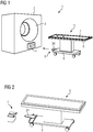
- Fig. 1 shows a medical examination device 1 in the form of a purely schematic diagram, comprising a magnetic resonance tomograph 2 with a bore 3 and a docking station 4 provided on the front, which includes mechanical coupling devices assigned to the tomograph, which will be discussed below.
- the examination device 1 also comprises a patient couch 5, which comprises a couch 6 with a table top 7 that can be moved horizontally in the longitudinal direction of the couch.
- a mechanical coupling device 9 is provided on a chassis 8 which interacts with the docking station 4 in order to bring the patient bed 5 into a defined position relative to the magnetic resonance tomograph 2.
- the patient bed 5 is moved in the direction of the magnetic resonance tomograph 2 by the operating staff, either manually or with automatic driving, so that the docking station 4 and the coupling device 9 are moved into one another, whereupon an automatic locking process begins, which is explained in more detail below.
- Fig. 2 shows the patient bed 5 in the form of a detailed view, as well as the docking station 4 as part of the magnetic resonance tomograph.
- a guide plate 34 is arranged on the chassis 8 of the patient bed 5, which has a conical basic shape and is provided with a radius contour on the edge.
- a driver 10, which represents a central coupling component of the patient bed 5, is arranged on its underside.
- an electrical coupling device 11 comprising a plug 12 is provided on the chassis, which cooperates with a corresponding coupling device on the docking station 4, which will also be discussed below. This plug 12 is exemplified in Fig. 3 shown.
- the docking station 4 has a corresponding housing 13 on which two centering plates 14 are provided on the upper side, on each of which two pairs of rollers 15, 16 are arranged at the front end.
- a tapering guide slot 17 remains between the two centering plates 14.
- the guide plate 34 is moved between the pairs of centering rollers 15, 16 and guided over them.
- the driver 10 or an upper collar 18 with a wider diameter engages in the guide slot 17 and is guided in it.
- the patient couch 5 is shifted until it is in a basic position from which the automatic mechanical coupling process can take place.
- an electrical coupling device 19 on the tomograph side is provided in the interior of the housing 13, which is designed as a socket 20 into which the plug 12 is automatically drawn during mechanical coupling, so that an electrical coupling also results at the same time.
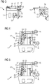
- Fig. 4 shows in the form of a schematic diagram with the omission of the centering plates 14, but with the corresponding centering rollers 15, 16, the docking station 4 and, as part of the patient couch 5, the driver 10. All other parts on the couch side are not shown for reasons of clarity.
- the conical guide plate 34 is guided laterally between the centering roller pairs 15, 16, the collar 18 is guided in the guide slot 17. This tour continues until an in Fig. 4 The basic position shown, which is detected by a sensor 21 installed on the docking station 4. In this basic position, the driver 10 is in a defined position relative to the mechanical coupling device 22 of the tomograph or the docking station 4.
- This mechanical coupling device 22 comprises a link component 23 with a driver groove 24, which link guide component 23 on a linear guide 25 in a direction perpendicular to Movement axis of the patient bed is displaceable.
- a spindle drive 26 comprising a spindle 27 and a nut 28 running thereon, shown here only with dashed lines, is provided.
- the link guide component which is guided in the linear guide 25 as described, is fastened to this nut 28.
- the threaded spindle 27 can be rotated via a drive motor 29, so that the nut 28 together with the link guide component 23 can be moved linearly.
- the basic position shown is the driver 10 quasi at the entrance of the driver groove 24, which is at an angle of approximately 45 ° relative to the axis of the linear guide 25 extends.
- the drive motor 29 is controlled via a control device of the magnetic resonance tomograph, not shown in detail, so that the threaded spindle 27 rotates and the nut 28 together with the link guide component 23 is moved along the linear guide 25.
- the driver 10 inevitably runs into the driver groove 24 and in this in a direction perpendicular to the axis of the linear guide 25.
- the end position is in FIG Fig. 5 shown.
- the driver 10 is at the bottom or the end of the driver groove 24 and, starting from the basic position according to FIG Fig. 4 , in a draw-in end position near the linear guide 25. That is, it was actively drawn into an end position by the pure linear displacement of the link guide component 23, automated by the drive motor 29.
- the patient bed 5 is mechanically firmly locked after on the one hand the driver 10 is in a fixed position and on the other hand the guide plate 34 is laterally fixed between the centering roller pairs 15, 16 and over the collar 18 in the guide gap 17.
- the link guide component consequently represents a pulling device which can be moved via the drive motor 29 together with the spindle drive 26 and via which the patient bed is automatically pulled into a defined end position.
- the plug 19 is also coupled to the socket 20, so that the patient bed is also electrically coupled to the docking station and the operation of the patient bed 5 or the automated displacement operation of the table top 7 is controlled via the control device of the magnetic resonance tomograph 2 can be.
- FIGS. 6 - 8 show, in the form of a purely schematic diagram, a further embodiment of a docking station 4 with its mechanical coupling device 22, the same reference numerals being used as far as possible for the same components.
- a link guide component 23 in the form of a disk 32 is rotatably mounted in a fixed position on a suitable carrier 30 via an axle bolt 31.
- the drive motor 29 attaches to the axle bolt 31, which means that the axle bolt 31 and with it the disk 32 can be rotated via the drive motor 29.
- Fig. 7 shows the basic position in the form of a schematic diagram, comparable to the diagram according to FIG Fig. 4 .
- the driver 10 shown here was detected again by a sensor, not shown in detail, so that it is ensured that it is in the basic position.
- the drive motor 29 is then activated via the control device on the tomograph side, so that the disk 32 is rotated.
- the disk 32 in turn has a driving groove 33, which here however winds from the outside inwards.
- the driver 10 is at the entrance of the driver groove 33. If the disk now rotates, the driver 10 is drawn into the driver groove 33; it moves in it due to the disk rotation to the end of the groove, which is significantly further inward relative to the disk edge is located.
- the disk 32 is a pulling device which can be moved via the drive motor 29 and which automatically pulls the patient bed into a defined end position.
- the corresponding side guides via the centering plates 14 with the centering roller pairs 15, 16 at the docking station 4 and the corresponding guide plate 34 with its conical and curved side shape are of course also provided, so that a corresponding side guide is also provided.
- a corresponding side guide is also provided.
- there is an exact mechanical coupling that is automatically implemented via the intake there is also the corresponding electrical coupling, since the connector on the patient side and the socket on the tomograph side are also provided in this embodiment.
- the disk 32 is rotated in the opposite direction via the drive motor 29.
- the driver 10 runs in this to the groove exit and is inevitably pushed away by the tomograph, and with it naturally also the patient bed 5.
- controllable drive motor 29 is arranged in the patient bed 5 and the driver 10 is arranged on an imaging device.
Landscapes
- Health & Medical Sciences (AREA)
- Life Sciences & Earth Sciences (AREA)
- Physics & Mathematics (AREA)
- Medical Informatics (AREA)
- Engineering & Computer Science (AREA)
- Nuclear Medicine, Radiotherapy & Molecular Imaging (AREA)
- Veterinary Medicine (AREA)
- Biophysics (AREA)
- General Health & Medical Sciences (AREA)
- Pathology (AREA)
- Public Health (AREA)
- Biomedical Technology (AREA)
- Heart & Thoracic Surgery (AREA)
- Molecular Biology (AREA)
- Surgery (AREA)
- Animal Behavior & Ethology (AREA)
- High Energy & Nuclear Physics (AREA)
- Radiology & Medical Imaging (AREA)
- Optics & Photonics (AREA)
- Magnetic Resonance Imaging Apparatus (AREA)
- Apparatus For Radiation Diagnosis (AREA)
Description
- Die Erfindung betrifft eine medizinische Untersuchungseinrichtung, umfassend ein Bildegebungsgerät, beispielsweise ein Magnetresonanztomograph, und eine mobile Patientenliege, wobei an beiden miteinander zu verbindende mechanische Kopplungseinrichtungen zum mechanischen Koppeln der Patientenliege an das Bildgebungsgerät in einer Endposition vorgesehen sind.
- Zur Durchführung einer Magnetresonanzuntersuchung wird häufig der Patient auf einer mobilen Patientenliege an den Magnetresonanztomographen gefahren. Diese Patientenliege umfasst zumeist eine horizontal verschiebbare Patientenaufnahme, mit welcher der Patient, wenn die Patientenliege am Magnetresonanztomographen positioniert ist, in die Bohrung gefahren wird. Um eine exakte Positionierung des Patienten zu ermöglichen, wird die mobile Patientenliege mechanisch mit dem Magnetresonanztomographen gekoppelt, so dass beide eine feste Relativposition zueinander einnehmen. Hierzu sind am Magnetresonanztomographen und der Patientenliege entsprechende mechanische Kopplungseinrichtungen vorgesehen, die miteinander zusammenwirken und die Patientenliege in einer Endposition fixieren. Eine exakte und positionsgenaue reversible Positionierung der Patientenliege ist absolut notwendig, um einen störungsfreien und sicheren Behandlungs- respektive Bildaufnahmebetrieb zu gewährleisten.
- Bei bisher bekannten Untersuchungseinrichtungen ist als liegenseitige Kopplungseinrichtung ein oder sind mehrere konische Zapfen vorgesehen, der oder die in entsprechende, die tomographenseitigen Kopplungseinrichtungen bildenden Gegenbuchsen eingreifen und bei weiterem Heranschieben der Liege an den Magnetresonanztomographen die richtige Andockposition finden. Die Bewegung der Patientenliege zur Andockstation am Magnetresonanztomographen erfolgt durch manuelles Heranschieben durch das Bedienpersonal. Die Enddurchmesser des oder der Zapfen sowie der einen oder mehreren Gegenbuchsen sind nahezu gleich groß, so dass damit zwangsläufig die Endposition gefunden wird. In der Endposition erfolgt die Verriegelung der Zapfen in den Buchsen, was mittels entsprechender Verriegelungshaken erfolgt, die das Bedienpersonal durch Drücken eines Fußpedals über ein hydraulisches System betätigt.
- Zwar kann hierüber eine sichere mechanische Fixierung erreicht werden, jedoch ist die Kopplung relativ umständlich, insbesondere aufgrund der erforderlichen Interaktion des Bedienpersonals.
WO 2013/115848 A1 offenbart eine medizinische Untersuchungseinrichtung mit einem Bildgebungsgerät und einer mobilen Patientenliege, welche einen Verriegelungsmechanismus aufweist, der mit einem Kupplungsmechanismus verbunden wird, um eine Bewegung der Patientenliege über einen motorgesteuerten Riemen in eine am Bildgebungsgerät befindliche Endposition zu ermöglichen. - Der Erfindung liegt damit die Aufgabe zugrunde, eine medizinische Untersuchungseinrichtung anzugeben, die demgegenüber verbessert ist und ein leichteres Andocken von Patientenliegen an Bildgebungsgeräten ermöglicht.
- Zur Lösung dieser Aufgabe ist bei einer Untersuchungseinrichtung der eingangs genannten Art erfindungsgemäß vorgesehen, dass die mechanische Kopplungseinrichtung des Bildgebungsgeräts eine über einen steuerbaren Antriebsmotor in eine Verriegelungsposition bewegbare Zugeinrichtung umfasst, die zum automatischen Bewegen der Patientenliege einen an der Patientenliege vorgesehenen Mitnehmer vor Erreichen der Endposition greift und durch Bewegen in die Verriegelungsposition mitnimmt, in der die Patientenliege in der Endposition ist.
- Alternativ ist zur Lösung dieser Aufgabe bei einer Untersuchungseinrichtung der eingangs genannten Art erfindungsgemäß vorgesehen, dass die mechanische Kopplungseinrichtung der Patientenliege eine über einen steuerbaren Antriebsmotor in eine Verriegelungsposition bewegbare Zugeinrichtung umfasst, die zum automatischen Bewegen der Patientenliege einen an dem Bildegebungsgerät vorgesehenen Mitnehmer vor Erreichen der Endposition greift und durch Bewegen in die Verriegelungsposition mitnimmt, in der die Patientenliege in der Endposition ist.
- Erfindungsgemäß ist tomographenseitig ein steuerbarer Antriebsmotor nebst einer über ihn bewegbaren Zugeinrichtung vorgesehen. Diese Zugeinrichtung ist über den Antriebsmotor zwischen einer Löseposition und einer Verriegelungsposition bewegbar. Wird die Patientenliege herangeschoben, so wird mit Erreichen einer entsprechenden Liegenposition der Antriebsmotor entsprechend angesteuert, so dass die Zugeinrichtung aus der Lösestellung bewegt wird. Während dieser Bewegung greift sie den liegenseitigen Mitnehmer. Mit fortgesetzter Bewegung der Zugeinrichtung in Richtung der Verriegelungsposition wird der Mitnehmer zwangsläufig mitgenommen und damit zwangsläufig die Patientenliege in Richtung des Magnetresonanztomographen bewegt. Mit Erreichen der Verriegelungsposition befindet sich die Patientenliege automatisch in der Endposition, in welcher sie exakt und definiert relativ zum Magnetresonanztomographen positioniert ist.
- Das Kopplungssystem der erfindungsgemäßen Untersuchungseinrichtung ist wesentlich einfacher aufgebaut, eine hydraulische Betätigungsvorrichtung, die irgendeine Interaktion des Bedienpersonals erfordert, ist nicht vorgesehen. Darüber hinaus wird durch die vorgesehene motorische Verriegelung die Patientenliege selbst in die definierte Endposition bewegt, so dass lediglich im Rahmen des Andockvorgangs seitens des Bedienpersonals die Patientenliege in eine Grundposition relativ zum Bildegbeungsgerät gebracht wird, in welcher die Zugeinrichtung den Mitnehmer greift. Von da an erfolgt der gesamte Kopplungsvorgang automatisch.
- Entsprechend einfach erfolgt nach Durchführung der Bildaufnahme die Entkopplung. Es ist lediglich erforderlich, den Antriebsmotor erneut anzusteuern, so dass er die Zugeinrichtung in die entgegengesetzte Richtung bewegt. Dies führt zum zwangsgeführten Herausschieben der Patientenliege aus der Verriegelungsstellung. Erreicht die Zugeinrichtung die Löseposition, so ist die Patientenliege wieder freigegeben, nachdem der Mitnehmer nicht mehr gegriffen ist. Auch hier ist folglich zum eigentlichen Lösen keine Interaktion des Bedienpersonals erforderlich, da auch hier eine automatische Bewegung der Patientenliege aus der gekoppelten Endposition heraus in eine Löseposition erfolgt.
- Nach einer ersten Erfindungsausgestaltung kann die Zugeinrichtung ein linear bewegbares Kulissenführungsbauteil mit einer den Mitnehmer aufnehmenden Mitnehmernut aufweisen. Die Mitnehmernut dient als Zwangsführung für den Mitnehmer, der während der Linearbewegung, initiiert über die den Antriebsmotor, in die Nut eingreift und in dieser geführt wird.
- Alternativ zur Verwendung eines linear bewegbaren Kulissenführungsbauteils kann auch ein um eine Drehachse drehbares Kulissenführungsbauteil mit einer den Mitnehmer aufnehmenden Mitnehmernut vorgesehen sein. Bei dieser Erfindungsausgestaltung erfolgt anstelle einer Linearbewegung eine Drehbewegung des Kulissenbauteils. Mit Herausdrehen aus der Lösestellung wird der Mitnehmer zwangsläufig in die Mitnehmernut eingeführt, in welcher er bei Fortsetzung der Drehbewegung bis zur Verriegelungsposition zwangsgeführt mitgenommen wird.
- Ist ein linear bewegbares Kulissenbauteil vorgesehen, so ist dieses zweckmäßigerweise an einer Linearführung bewegbar geführt, wobei die Zugeinrichtung einen Spindeltrieb mit einer Gewindespindel und einer auf dieser geführten Mutter, mit der das Kulissenführungsbauteil gekoppelt ist, umfasst, wobei die Gewindespindel über den Antriebsmotor antreibbar ist. Über die Linearführung ist das Kulissenbauteil exakt und hinreichend stabil geführt. Über den Spindeltrieb, dessen Gewindespindel über den Antriebsmotor angetrieben wird, kann das Kulissenführungsbauteil auf einfache Weise zwischen der Löse-und der Verriegelungsstellung bewegt werden. Dabei ist das Kulissenführungsbauteil an der Linearführung bevorzugt längs einer senkrecht zur Bewegungsrichtung der Patientenliege verlaufenden Linearachse geführt. Das heißt, es bewegt sich folglich senkrecht zur Patientenliege. Die Mitnehmernut verläuft unter einem Winkel zur Linearachse, der bevorzugt zwischen 30° - 60° liegt. Durch den gewinkelten Verlauf der Mitnehmernut ist die Zwangsführung des Mitnehmers und damit das Heranziehen der Liege an das Bildegebungsgerät sichergestellt, wenn das Kulissenführungsbauteil senkrecht zur Patientenliegenachse bewegt wird. Je nach dem gegebenen Winkel ergibt sich bei gleicher linearer Verschiebungslänge ein kleinerer oder größerer linearer Bewegungsweg der Patientenliege, gesehen von der Eingriffsposition des Mitnehmers in die Nut bis zum Erreichen der Endposition.
- Das alternativ verwendbare drehbare Kulissenführungsbauteil ist gemäß einer Weiterbildung der Erfindung an einem drehgelagerten Achsbolzen angeordnet, wobei der Antriebsmotor den Achsbolzen antreibt. Das Kulissenführungsbauteil, das bevorzugt eine Scheibe ist, wird über den Antriebsmotor zwischen der Löse- und der Verriegelungsstellung verdreht, wobei hierfür beispielsweise eine Verdrehung um 180° erfolgt. Die Mitnehmernut verläuft bei dieser Erfindungsausgestaltung gebogen zum Scheibeninneren hin, so dass sich zwangsläufig eine lineare Zugbewegung ergibt.
- Gemäß einer besonders vorteilhaften Weiterbildung ist wenigstens ein Sensor vorgesehen, über den die Position der Patientenliege, insbesondere die Position des Mitnehmers erfassbar ist, wobei der Antriebsmotor in Abhängigkeit des Erfassungsergebnisses des Sensors steuerbar ist. Wird die Patientenliege vom Bedienpersonal in Richtung des Bildegbeungsgeräts geschoben, so nähert sie sich zwangsläufig der Andockstation an das Bildegbungsgerät an, also der dortigen Kopplungseinrichtung. Diese Annäherungsbewegung wird über einen Sensor überwacht. Erfasst nun der Sensor, der beispielsweise die Position des Mitnehmers sensiert, dass sich der Mitnehmer in einer entsprechend definierten Grundposition befindet, so wird ein entsprechendes Signal an eine Steuerungseinrichtung gegeben, die daraufhin hierüber quasi getriggert den Antriebsmotor ansteuert, so dass dieser das Kulissenführungsbauteil entsprechend bewegt. Der Sensor erfasst also, wenn sich der Mitnehmer in der Eingriffsposition, in der er in die Nut eingreifen kann, befindet. Sobald das Kulissenführungsbauteil bewegt wird, wird der Mitnehmer in die Nut eingeführt, woraufhin sich die automatische Zugbewegung einstellt. Der Einzug wird also automatisch gestartet.
- An der Patientenliege ist bevorzugt ein den Mitnehmer tragendes Führungsbauteil vorgesehen, das beim Heranfahren an den Magnetresonanztomographen zwischen zwei an der dortigen Kupplungseinrichtung angeordnete Führungsrollen greift, von denen es bis zum Erreichen der Endposition geführt ist. Über dieses Führungsbauteil ist folglich eine beidseitige Führung gegeben, das heißt, dass die Patientenliege während der automatischen Einzugsbewegung seitengeführt ist. Diese Führungsrollen sind bevorzugt jeweils doppelt an beiden Seiten des Einzugskanals respektive der Einzugsebene vorgesehen, so dass das Führungsbauteil an jeder Seite folglich doppelt abgestützt respektive geführt ist. Bevorzugt ist das Führungsbauteil eine konische, randseitig gegebenenfalls mit einer Radiuskontur versehene Führungsplatte.
- Um auch eine elektrisch Kopplung der Patientenliege mit dem Bildegebungsgerät durch den automatischen Einzug sicherzustellen, was erforderlich ist, um über eine zentrale Steuerungseinrichtung des Bildgebungsgeräts den Bewegungsweg der Tischplatte, die wie einleitend beschrieben automatisch über einen entsprechenden Antriebsmotor verfahrbar ist, zu steuern, sieht die Erfindung ferner an dem Bildgebungsgerät und der Patientenliege elektrische Kopplungseinrichtungen zum elektrischen Koppeln der Patientenliege an das Bildgebungsgerät in der Endposition vor, die spätestens mit Erreichen der Endposition automatisch miteinander verbunden sind. Die Kopplungseinrichtungen sind dabei z. B. als Stecker-Buchsen-Paar ausgeführt. Wird folglich im Rahmen des automatischen Einzugs die Patientenliege in die Endposition gezogen, so werden dabei automatisch auch der Stecker und die Buchse, elektrisch kontaktierend, zusammengefahren. Dies ist, da die Einzugsbewegung eine reine Linearbewegung ist und in eine definierte Endposition mündet, ohne weiteres möglich, das heißt, dass der Stecker exakt in die Buchse eingeführt wird, ohne dass irgend eine Interaktion seitens des Bedienpersonals erforderlich ist. Dabei können den elektrischen Kopplungseinrichtungen beim Zusammenfahren miteinander zusammenwirkende Zentriervorrichtungen zugeordnet sein. Beispielsweise kann an dem liegenseitigen Stecker eine konusartige, ihn umgebende Außenkontur vorgesehen sein, die in eine entsprechende, die bildgebungsgerätseitige Buchse umgebende konusartige Innenkontur gefahren wird und ähnliches.
- Mitunter ist die Patientenliege mit einem eigenen Antriebsmotor versehen, der wenigstens zwei liegenseitige Rollen antreibt, so dass die Liege selbstfahrend ist. Über diesen eigenen Antrieb kann die Liege bis nahe an das Bildgebungsgerät fahren. Um bei einer solchen Liegenausgestaltung nun den automatischen Einzug zuzulassen, ohne dass eine liegenseitige Rolle gesperrt ist, nachdem sie wie beschrieben mit den Antriebsmotor gekoppelt ist, ist es zweckmäßig, wenn ein Sensor an der Liege vorgesehen ist, der eine Annäherung der Patientenliege an das Bildgebungsgerät erfasst, wobei die Rollen in Abhängigkeit der Sensorerfassung leerlaufend geschaltet werden. Das heißt, dass entweder die Rollen vom Antriebsmotor entkoppelt werden oder dass der Antriebsmotor leerlaufend geschaltet wird, so dass die Rollen frei drehen können und die Zugeinrichtung nach Greifen des Mitnehmers die Liege in die Endposition ziehen kann.
- Weitere Vorteile, Merkmale und Einzelheiten ergeben sich aus dem im Folgenden beschriebenen Ausführungsbeispiel sowie anhand der Zeichnungen. Die Erfindung selbst wird durch die unabhängigen Vorrichtungansprüche 1 und 2 definiert. Weitere Ausführungsbeispiele werden durch Ansprüche 3-15 definiert. Dabei zeigen:
- Fig. 1
- eine Prinzipdarstellung einer erfindungsgemäßen medizinischen Untersuchungseinrichtung,
- Fig. 2
- eine Teilansicht der Patientenliege und der tomographenseitigen Andockstation,
- Fig. 3
- eine vergrößerte Teilansicht der Patientenliege und der Andockstation mit den mechanischen Kopplungseinrichtungen,
- Fig. 4
- eine Teilansicht der Andockstation des Magnetresonanztomographen nebst Darstellung des liegenseitigen Mitnehmers in einer Ausgangsstellung vor dem Beginn der mechanischen Kopplung,
- Fig. 5
- die Ansicht aus
Fig. 4 nach der mechanischen Kopplung, - Fig. 6
- eine Prinzipdarstellung eines Teils einer Andockstation einer zweiten Ausführungsform in einer Seitenansicht,
- Fig. 7
- die Darstellung aus
Fig. 6 in einer Aufsicht mit Darstellung des liegenseitigen Mitnehmers in einer Grundstellung vor dem Beginn des Kopplungsvorgangs, und - Fig. 8
- die Darstellung gemäß
Fig. 7 am Ende des Kopplungsvorgangs. - Im Folgenden wird beispielhaft anhand eines Magnetresonanztomographs ein Ausführungsbeispiel beschrieben. Ausführungsformen mit anderen Bildgebungsgeräten, beispielsweise Computertomographen der Röntgenbildgebung, sind analog aufgebaut.
-
Fig. 1 zeigt eine medizinische Untersuchungseinrichtung 1 in Form einer reinen Prinzipdarstellung, umfassend einen Magnetresonanztomographen 2 mit einer Bohrung 3 sowie einer frontseitig vorgesehenen Andockstation 4, die mechanische Kopplungseinrichtungen, die dem Tomographen zugeordnet sind, umfasst, worauf nachfolgend noch eingegangen wird. - Die Untersuchungseinrichtung 1 umfasst ferner eine Patientenliege 5, die einen Liegentisch 6 mit einer horizontal in Liegenlängsrichtung verfahrbaren Tischplatte 7 umfasst. An einem Fahrgestell 8 ist eine mechanische Kopplungseinrichtung 9 vorgesehen, die mit der Andockstation 4 zusammenwirkt, um die Patientenliege 5 in eine definierte Position relativ zum Magnetresonanztomographen 2 zu bringen. Im Betrieb wird die Patientenliege 5 vom Bedienpersonal entweder manuell oder bei automatischem Fahrbetrieb entsprechend gesteuert in Richtung des Magnetresonanztomographen 2 bewegt, so dass die Andockstation 4 und die Kopplungseinrichtung 9 ineinandergefahren werden, woraufhin ein automatischer Verriegelungsvorgang einsetzt, der nachfolgend näher erläutert wird.
-
Fig. 2 zeigt in Form einer Detailansicht die Patientenliege 5, sowie als Teil des Magnetresonanztomographen die dortige Andockstation 4. Am Fahrgestell 8 der Patientenliege 5 ist eine Führungsplatte 34 angeordnet, die eine konische Grundform besitzt und randseitig mit einer Radiuskontur versehen ist. An ihrer Unterseite ist ein Mitnehmer 10 angeordnet, der ein zentrales Kopplungsbauteil der Patientenliege 5 darstellt. Des Weiteren ist am Fahrgestell eine elektrische Kopplungseinrichtung 11 umfassend einen Stecker 12 vorgesehen, der mit einer entsprechenden Kopplungseinrichtung an der Andockstation 4 zusammenwirkt, worauf nachfolgend ebenfalls noch eingegangen wird. Dieser Stecker 12 ist exemplarisch inFig. 3 gezeigt. - Die Andockstation 4 weist ein entsprechendes Gehäuse 13 auf, an dem oberseitig zwei Zentrierplatten 14 vorgesehen sind, an denen am vorderen Ende jeweils zwei Rollenpaare 15, 16 angeordnet sind. Zwischen den beiden Zentrierplatten 14 verbleibt ein sich verjüngender Führungsschlitz 17. Beim Zusammenfahren von Patientenliege 5 und Andockstation 4 wird die Führungsplatte 34 zwischen die Zentrierrollenpaare 15, 16 bewegt und hierüber geführt. Gleichzeitig greift der Mitnehmer 10 respektive ein oberer, im Durchmesser verbreiteter Kragen 18 in den Führungsschlitz 17 und wird in diesem geführt. Die Patientenliege 5 wird soweit verschoben, bis sie in einer Grundposition ist, ausgehend von welcher der automatische mechanische Kopplungsvorgang erfolgen kann. Wie
Fig. 3 zu entnehmen ist, ist im Inneren des Gehäuses 13 eine tomographenseitige elektrische Kopplungseinrichtung 19 vorgesehen, die als Buchse 20 ausgeführt ist, in die der Stecker 12 automatisch beim mechanischen Koppeln eingezogen wird, so dass sich gleichzeitig auch eine elektrische Kopplung ergibt. -
Fig. 4 zeigt in Form einer Prinzipdarstellung unter Weglassung insbesondere der Zentrierplatten 14, jedoch unter Darstellung der entsprechenden Zentrierrollen 15, 16, die Andockstation 4 sowie als Teil der Patientenliege 5 den Mitnehmer 10. Sämtliche anderen liegenseitigen Teile sind aus Übersichtlichkeitsgründen nicht gezeigt. Wie beschrieben ist die konische Führungsplatte 34 zwischen den Zentrierrollenpaaren 15, 16 seitlich geführt, der Kragen 18 ist im Führungsschlitz 17 geführt. Diese Führung erfolgt bis zum Erreichen einer inFig. 4 gezeigten Grundstellung, die über einen an der Andockstation 4 verbauten Sensor 21 erfasst wird. In dieser Grundstellung befindet sich der Mitnehmer 10 in einer definierten Position relativ zu der mechanischen Kopplungseinrichtung 22 des Tomographen respektive der Andockstation 4. Diese mechanische Kopplungseinrichtung 22 umfasst ein Kulissenbauteil 23 mit einer Mitnehmernut 24, welches Kulissenführungsbauteil 23 an einer Linearführung 25 in einer Richtung senkrecht zur Bewegungsachse der Patientenliege verschiebbar ist. Hierzu ist ein Spindeltrieb 26 umfassend eine Spindel 27 sowie eine darauf laufende Mutter 28, hier nur gestrichelt dargestellt, vorgesehen. An dieser Mutter 28 ist das Kulissenführungsbauteil befestigt, das wie beschrieben in der Linearführung 25 geführt ist. Über einen Antriebsmotor 29 ist die Gewindespindel 27 drehbar, so dass die Mutter 28 nebst Kulissenführungsbauteil 23 linear bewegt werden kann. - In der in
Fig. 4 gezeigten Grundstellung befindet sich der Mitnehmer 10 quasi am Eingang der Mitnehmernut 24, die sich unter einem Winkel von ca. 45° relativ zur Achse der Linearführung 25 erstreckt. Mit Gabe des Erfassungssignals über den Sensor 21 wird über eine nicht näher gezeigte Steuerungseinrichtung des Magnetresonanztomographen der Antriebsmotor 29 angesteuert, so dass die Gewindespindel 27 rotiert und die Mutter 28 nebst Kulissenführungsbauteil 23 längs der Linearführung 25 bewegt wird. Durch diese Bewegung läuft der Mitnehmer 10 zwangsläufig in die Mitnehmernut 24 und in dieser in einer Richtung senkrecht zur Achse der Linearführung 25. Die Endposition ist inFig. 5 dargestellt. Ersichtlich befindet sich der Mitnehmer 10 am Grund respektive Ende der Mitnehmernut 24 und, ausgehend von der Grundposition gemäßFig. 4 , in einer Einzugsendstellung nahe der Linearführung 25. Das heißt, dass er durch die reine, über den Antriebsmotor 29 automatisierte Linearverschiebung des Kulissenführungsbauteils 23 aktiv in eine Endposition eingezogen wurde. In dieser ist die Patientenliege 5 mechanisch fest verriegelt, nachdem einerseits der Mitnehmer 10 in einer festen Position ist, andererseits die Führungsplatte 34 zwischen dem Zentrierrollenpaaren 15, 16 und über den Kragen 18 in dem Führungsspalt 17 seitlich festgelegt ist. Das Kulissenführungsbauteil stellt folglich eine über den Antriebsmotor 29 nebst Spindeltrieb 26 bewegbare Zugeinrichtung dar, über die die Patientenliege automatisch in eine definierte Endstellung gezogen wird. - Gleichzeitig mit dem automatischen Einziehen kommt es auch zu einer Kopplung des Steckers 19 mit der Buchse 20, so dass die Patientenliege auch elektrisch mit der Andockstation gekoppelt ist und der Betrieb der Patientenliege 5 respektive der automatisierte Verschiebebetrieb der Tischplatte 7 über die Steuerungseinrichtung des Magnetresonanztomographen 2 gesteuert werden kann.
- Ähnlich einfach und automatisiert wie die Einzugsbewegung gestaltet sich auch das erneute Lösen der Kopplung. Hierzu ist es lediglich erforderlich, bei Gabe eines entsprechenden Ansteuersignals den Antriebsmotor 29 in die entgegengesetzte Richtung zu betreiben, so dass die Gewindespindel 27 ebenfalls in die entgegengesetzte Richtung rotiert und die Mutter 28 ausgehend von der in
Fig. 5 gezeigten Endposition wieder in die inFig. 4 gezeigte Grundstellung zurückwandert. Hierbei läuft der Mitnehmer 10 aus der Mitnehmernut 24 heraus, er und mit ihm die Patientenliege 5 wird in die entgegengesetzte Richtung automatisch ausgeschoben. Mit Erreichen der Grundstellung gemäßFig. 4 kann die Patientenliege 5 wieder manuell oder durch ihren eigenen Antrieb vom Tomographen 2 weggefahren werden. Gleichzeitig geht damit natürlich auch eine automatische Entkopplung der elektrischen Kopplung einher. - Die
Figuren 6 - 8 zeigen in Form einer reinen Prinzipdarstellung eine weitere Ausführungsform einer Andockstation 4 mit deren mechanischen Kopplungseinrichtung 22, wobei soweit möglich für gleiche Bauteile gleiche Bezugszeichen verwendet werden. Am hier nur prinzipiell dargestellten Gehäuse 13 ist an einem geeigneten Träger 30 über einen Achsbolzen 31 ein Kulissenführungsbauteil 23 in Form einer Scheibe 32 positionsfest drehgelagert. Am Achsbolzen 31 setzt der Antriebsmotor 29 an, das heißt, dass der Achsbolzen 31 und mit ihm die Scheibe 32 über den Antriebsmotor 29 gedreht werden können. -
Fig. 7 zeigt in Form einer Prinzipdarstellung die Grundstellung, vergleichbar mit der Darstellung gemäßFig. 4 . Der hier dargestellte Mitnehmer 10 wurde wieder über einen nicht näher gezeigten Sensor erfasst, so dass sichergestellt ist, dass er sich in der Grundstellung befindet. Hieraufhin wird über die tomographenseitige Steuerungseinrichtung der Antriebsmotor 29 angesteuert, so dass die Scheibe 32 verdreht wird. Die Scheibe 32 weist wiederum eine Mitnehmernut 33 auf, die sich hier jedoch von außen nach innen windet. In der Grundstellung befindet sich der Mitnehmer 10 am Eingang der Mitnehmernut 33. Rotiert nun die Scheibe, so wird der Mitnehmer 10 in die Mitnehmernut 33 eingezogen, er wandert in ihr bedingt durch die Scheibenrotation zum Nutende, das sich deutlich weiter innen bezogen auf den Scheibenrand befindet. In der Endstellung befindet er sich vollständig in der Mitnehmernut 33 eingezogen, sieheFig. 8 Ersichtlich bewegt er sich also auch hier linear zum Magnetresonanztomographen 2 hin, was zwangsläufig auch zu einem entsprechenden Einzug der Patientenliege 5 führt. Die Scheibe 32 ist auch hier eine über den Antriebsmotor 29 bewegbare Zugeinrichtung, die die Patientenliege in eine definierte Endstellung automatisch zieht. - Wenngleich hier nicht näher dargestellt, sind selbstverständlich auch die entsprechenden Seitenführungen über die Zentrierplatten 14 mit den Zentrierrollenpaaren 15, 16 an der Andockstation 4 sowie die entsprechende Führungsplatte 34 mit ihrer konischen und gewölbten Seitenform vorgesehen, so dass auch eine entsprechende Seitenführung gegeben ist. Wiederum ist eine exakte, automatisch über den Einzug realisierte mechanische Kopplung gegeben. Gleichzeitig ergibt sich natürlich auch die entsprechende elektrische Kopplung, da auch bei dieser Ausgestaltung der liegenseitige Stecker und die tomographenseitige Buchse vorgesehen sind.
- Zum erneuten Lösen der Kopplung wird die Scheibe 32 über den Antriebsmotor 29 in die entgegengesetzte Richtung gedreht. Es kommt wiederum zu einer entsprechenden Zwangsführung des Mitnehmers 10 in der Mitnehmernut 33, er läuft in dieser zum Nutausgang und wird dabei zwangsläufig vom Tomographen weggeschoben, damit einhergehend natürlich auch die Patientenliege 5.
- Obwohl die Erfindung im Detail durch das bevorzugte Ausführungsbeispiel näher illustriert und beschrieben wurde, so ist die Erfindung nicht durch die offenbarten Beispiele eingeschränkt und die Erfindung wird durch die Ansprüche definiert. Insbesondere ist auch eine umgekehrte Anordnung möglich, bei der der steuerbare Antriebsmotor 29 in der Patientenliege 5 und der Mitnehmer 10 an einem Bildgebungsgerät angeordnet ist.
-
- 1
- Untersuchungseinrichtung
- 2
- Bildgebungsgerät / Magnetresonanztomograph
- 3
- Bohrung
- 4
- Andockstation
- 5
- Patientenliege
- 6
- Liegentisch
- 7
- Tischplatte
- 8
- Fahrgestell
- 9
- Kopplungseinrichtung
- 10
- Mitnehmer
- 11
- Kopplungseinrichtung
- 12
- Stecker
- 13
- Gehäuse
- 14
- Zentrierplatten
- 15
- Rollenpaar
- 16
- Rollenpaar
- 17
- Führungsschlitz
- 18
- Kragen
- 19
- Kopplungseinrichtung
- 20
- Buchse
- 21
- Sensor
- 22
- Kopplungseinrichtung
- 23
- Kulissenbauteil
- 24
- Mitnehmernut
- 25
- Linearführung
- 26
- Spindeltrieb
- 27
- Spindel
- 28
- Mutter
- 29
- Antriebsmotor
- 30
- Träger
- 31
- Achsbolzen
- 32
- Scheibe
- 33
- Mitnehmernut
- 34
- Führungsplatte
Claims (15)
- Medizinische Untersuchungseinrichtung (1), umfassend ein Bildgebungsgerät (2) und eine mobile Patientenliege, wobei an beiden miteinander zu verbindende mechanische Kopplungseinrichtungen zum mechanischen Koppeln der Patientenliege (5) an das Bildgebungsgerät (2) in einer Endposition vorgesehen sind, wobei die Patientenliege einen Liegentisch (6) mit einer horizontal in Liegenlängsrichtung verfahrbaren Tischplatte (7) und ein Fahrgestell (8) umfasst und die mechanische Kopplungseinrichtung der Patientenliege (5) an dem Fahrgestell (8) angeordnet ist, wobei die mechanische Kopplungseinrichtung (22) des Bildgebungsgeräts (2) eine über einen steuerbaren Antriebsmotor (29) in eine Verriegelungsposition bewegbare Zugeinrichtung (23) umfasst, die zum automatischen Bewegen der Patientenliege (5) einen an der Patientenliege (5) vorgesehenen Mitnehmer (10) vor Erreichen der Endposition greift und durch Bewegen in die Verriegelungsposition mitnimmt, in der die Patientenliege (5) in der Endposition ist dadurch gekennzeichnet, dass die Zugeinrichtung ein linear bewegbares oder ein um eine Drehachse drehbares Kulissenführungsbauteil (23) mit einer den Mitnehmer (10) aufnehmenden Mitnehmernut (24, 33) aufweist.
- Medizinische Untersuchungseinrichtung (1), umfassend ein Bildgebungsgerät (2) und eine mobile Patientenliege, wobei an beiden miteinander zu verbindende mechanische Kopplungseinrichtungen zum mechanischen Koppeln der Patientenliege (5) an das Bildgebungsgerät (2) in einer Endposition vorgesehen sind, wobei die Patientenliege (5) einen Liegentisch (6) mit einer horizontal in Liegenlängsrichtung verfahrbaren Tischplatte (7) und ein Fahrgestell (8) umfasst und die mechanische Kopplungseinrichtung der Patientenliege (5) an dem Fahrgestell (8) angeordnet ist, wobei die mechanische Kopplungseinrichtung (22) der Patientenliege (5) eine über einen steuerbaren Antriebsmotor (29) in eine Verriegelungsposition bewegbare Zugeinrichtung (23) umfasst, die zum automatischen Bewegen der Patientenliege (5) einen an dem Bildgebungsgerät (2) vorgesehenen Mitnehmer (10) vor Erreichen der Endposition greift und durch Bewegen in die Verriegelungsposition mitnimmt, in der die Patientenliege (5) in der Endposition ist, dadurch gekennzeichnet, dass die Zugeinrichtung ein linear bewegbares oder ein um eine Drehachse drehbares Kulissenführungsbauteil (23) mit einer den Mitnehmer (10) aufnehmenden Mitnehmernut (24, 33) aufweist.
- Medizinische Untersuchungseinrichtung nach Anspruch 1 oder 2, dadurch gekennzeichnet, dass das linear bewegbare Kulissenführungsbauteil (23) an einer Linearführung (25) bewegbar geführt ist, wobei die Zugeinrichtung einen Spindeltrieb (26) mit einer Gewindespindel (27) und einer auf dieser geführten Mutter (28), mit der das Kulissenführungsbauteil (23) gekoppelt ist, umfasst, wobei die Gewindespindel (27) über den Antriebsmotor (29) antreibbar ist.
- Medizinische Untersuchungseinrichtung nach Anspruch 3, dadurch gekennzeichnet, dass das Kulissenführungsbauteil (23) an der Linearführung (25) längs einer senkrecht zur Bewegungsrichtung der Patientenliege (5) verlaufenden Linearachse geführt ist.
- Medizinische Untersuchungseinrichtung nach Anspruch 4, dadurch gekennzeichnet, dass die Mitnehmernut (24) unter einem Winkel zwischen 30° - 60° zur Linearachse verläuft.
- Medizinische Untersuchungseinrichtung nach Anspruch nach einem der vorhergehenden Ansprüche, dadurch gekennzeichnet, dass das drehbare Kulissenführungsbauteil (23) an einem drehgelagerten Achsbolzen (31) angeordnet ist, wobei der Antriebsmotor (29) den Achszapfen (31) antreibt.
- Medizinische Untersuchungseinrichtung nach Anspruch 6, dadurch gekennzeichnet, dass das Kulissenführungsbauteil (23) eine Scheibe (32) mit einer gebogen zum Scheibeninneren hin geführten Mitnehmernut (33) ist.
- Medizinische Untersuchungseinrichtung nach einem der vorangehenden Ansprüche, dadurch gekennzeichnet, dass wenigstens ein Sensor (21) vorgesehen ist, über den die Position der Patientenliege (5), insbesondere die Position des Mitnehmer (10) erfassbar ist, wobei der Antriebsmotor (29) in Abhängigkeit des Erfassungsergebnisses des Sensors (21) steuerbar ist.
- Medizinische Untersuchungseinrichtung nach einem der vorangehenden Ansprüche, dadurch gekennzeichnet, dass an der Patientenliege (5) oder dem Bildgebungsgerät (2) ein den Mitnehmer (10) tragendes Führungsbauteil (9) vorgesehen ist, das beim Heranfahren an das Bildgebungsgerät (2) zwischen zwei an der dortigen Kopplungseinrichtung (22) angeordnete Führungsrollen (15, 16) greift, von denen es bis zum Erreichen der Endposition geführt ist.
- Medizinische Untersuchungseinrichtung nach Anspruch 9, dadurch gekennzeichnet, dass zwei einander gegenüberliegende Paare von Führungsrollen (15, 16) vorgesehen sind.
- Medizinische Untersuchungseinrichtung nach Anspruch 9 oder 10, dadurch gekennzeichnet, dass das Führungsbauteil eine konische, randseitig gegebenenfalls mit einer Radiuskontur versehene Führungsplatte (34) ist.
- Medizinische Untersuchungseinrichtung nach einem der vorangehenden Ansprüche, dadurch gekennzeichnet, dass an dem Bildgebungsgerät (2) und der Patientenliege (5) ferner elektrische Kopplungseinrichtungen (12, 20) zum elektrischen Koppeln der Patientenliege (5) an das Bildgebungsgerät (2) in der Endposition vorgesehen sind, die spätestens mit Erreichen der Endposition automatisch miteinander verbunden sind.
- Medizinische Untersuchungseinrichtung nach Anspruch 12, dadurch gekennzeichnet, dass die Kopplungseinrichtungen als Stecker-Buchsen-Paar (12, 20) ausgeführt sind.
- Medizinische Untersuchungseinrichtung nach Anspruch 12 oder 13, dadurch gekennzeichnet, dass den elektrischen Kopplungseinrichtungen (12, 20) beim Zusammenfahren miteinander zusammenwirkende Zentriervorrichtungen zugeordnet sind.
- Medizinische Untersuchungseinrichtung nach einem der vorangehenden Ansprüche, dadurch gekennzeichnet, dass die Patientenliege (5) wenigstens zwei über einen liegenseitigen Antriebsmotor antreibbare Rollen aufweist, und dass ein Sensor vorgesehen ist, der eine Annäherung der Patientenliege (5) an das Bildgebungsgerät (2) erfasst, wobei die Rollen in Abhängigkeit der Sensorerfassung leerlaufend geschaltet werden.
Applications Claiming Priority (2)
| Application Number | Priority Date | Filing Date | Title |
|---|---|---|---|
| DE102014205537 | 2014-03-25 | ||
| DE102014211269.9A DE102014211269A1 (de) | 2014-03-25 | 2014-06-12 | Medizinische Untersuchungseinrichtung |
Publications (2)
| Publication Number | Publication Date |
|---|---|
| EP2923640A1 EP2923640A1 (de) | 2015-09-30 |
| EP2923640B1 true EP2923640B1 (de) | 2021-07-21 |
Family
ID=52350021
Family Applications (1)
| Application Number | Title | Priority Date | Filing Date |
|---|---|---|---|
| EP15151431.2A Active EP2923640B1 (de) | 2014-03-25 | 2015-01-16 | Medizinische Untersuchungseinrichtung |
Country Status (5)
| Country | Link |
|---|---|
| US (1) | US9861326B2 (de) |
| EP (1) | EP2923640B1 (de) |
| KR (1) | KR101698738B1 (de) |
| CN (1) | CN104939827B (de) |
| DE (1) | DE102014211269A1 (de) |
Families Citing this family (15)
| Publication number | Priority date | Publication date | Assignee | Title |
|---|---|---|---|---|
| DE102013208650B4 (de) * | 2013-05-10 | 2016-10-06 | Siemens Healthcare Gmbh | Transportvorrichtung zum Tragen eines Patienten mit einer Andockvorrichtung, System mit einer Transportvorrichtung und zugehöriges Verfahren |
| WO2017007450A1 (en) * | 2015-07-06 | 2017-01-12 | Kona Medical, Inc. | Integrated patient platform |
| US10835430B2 (en) * | 2016-09-02 | 2020-11-17 | Stryker Corporation | Patient mobility system with integrated ambulation device |
| DE102016225689A1 (de) * | 2016-12-20 | 2018-06-21 | Kuka Roboter Gmbh | Patientenpositioniervorrichtung und medizinische Anlage |
| KR102168714B1 (ko) * | 2019-04-25 | 2020-10-22 | 제이피아이헬스케어 주식회사 | Rad, flo, lt 및 cbct 촬영이 가능한 복합 엑스선 촬영장치 |
| US11684327B2 (en) * | 2019-09-02 | 2023-06-27 | Cefla Societá Cooperativa | Patient table with lock and unlock device and improved safety arrangements |
| IT201900015333A1 (it) * | 2019-09-02 | 2021-03-02 | Cefla Soc Cooperativa | Lettino paziente con meccanismo di blocco/sblocco |
| CN110584669A (zh) * | 2019-09-26 | 2019-12-20 | 山东朗润医疗系统有限公司 | 一种信号同步的磁共振成像装置 |
| US11925586B2 (en) | 2022-03-25 | 2024-03-12 | Mazor Robotics Ltd. | Surgical platform and trolley assembly |
| US12207946B2 (en) | 2022-05-10 | 2025-01-28 | Warsaw Orthopedic, Inc. | Surgical platform system |
| EP4371544A4 (de) * | 2022-09-29 | 2024-10-23 | Shanghai United Imaging Healthcare Co., Ltd. | Verfahren und system zur steuerung des andockens eines mobilen krankenbetts an eine medizinische vorrichtung |
| KR102601103B1 (ko) * | 2022-11-28 | 2023-11-10 | 제이피아이헬스케어 주식회사 | 침대와 정렬을 하는 cbct장치 및 장치의 동작 방법 |
| US20240315650A1 (en) * | 2023-03-21 | 2024-09-26 | GE Precision Healthcare LLC | Systems and methods for stabilizing a patient lift with a medical imaging table |
| US12539244B2 (en) | 2023-05-26 | 2026-02-03 | Warsaw Orthopedic, Inc. | Surgical gantry and interface moveably interconnecting surgical table and gantry |
| DE102024202589B4 (de) * | 2024-03-19 | 2025-12-18 | Siemens Healthineers Ag | Koppelsystem zum Koppeln einer Patientenliege mit einem medizinischen Bildgebungssystem |
Citations (1)
| Publication number | Priority date | Publication date | Assignee | Title |
|---|---|---|---|---|
| WO2013115848A1 (en) * | 2012-02-02 | 2013-08-08 | Cincinnati Children's Hospital Medical Center | Mri transfer station and dock |
Family Cites Families (17)
| Publication number | Priority date | Publication date | Assignee | Title |
|---|---|---|---|---|
| US4567894A (en) * | 1984-11-09 | 1986-02-04 | General Electric Company | Hydraulically operated, mobile patient transport table useful with a magnetic resonance scanner |
| US4727328A (en) * | 1985-11-15 | 1988-02-23 | Technicare Corporation | Patient handling arrangements for NMR imaging systems |
| US5499415A (en) * | 1994-02-08 | 1996-03-19 | Analogic Corporation | Stabilized, cantilevered, patient trauma table system |
| DE4423374C2 (de) * | 1994-07-04 | 2000-01-05 | Maquet Ag | Verbindungseinrichtung zum wahlweisen Verbinden einer Patientenlagerfläche mit der Stützsäule eines Operationstisches |
| JPH11197197A (ja) | 1998-01-12 | 1999-07-27 | Toshiba Iyou System Engineering Kk | 患者移動装置 |
| DE19929654C1 (de) * | 1999-06-28 | 2001-05-10 | Siemens Ag | Koppeleinrichtung für eine Antriebseinrichtung und eine verstellbare Lagerungsplatte einer medizinischen Einrichtung |
| AU2003276628A1 (en) * | 2002-11-27 | 2004-06-18 | Koninklijke Philips Electronics N.V. | Method and apparatus for automatic self-aligning docking of a couch with a magnetic resonance imaging scanner |
| US7970452B2 (en) * | 2003-09-30 | 2011-06-28 | Hologic, Inc. | Open architecture imaging apparatus and coil system for magnetic resonance imaging |
| US7748511B1 (en) * | 2005-03-25 | 2010-07-06 | Nelson Whittaker | Vending system for wheeled vehicles |
| WO2006126108A1 (en) * | 2005-05-25 | 2006-11-30 | Koninklijke Philips Electronics N.V. | Off-magnet patient scan positioning |
| DE102005054220B4 (de) * | 2005-11-14 | 2024-12-05 | MAQUET GmbH | Patientenlagersystem |
| DE102005054174A1 (de) * | 2005-11-14 | 2007-05-16 | Maquet Gmbh & Co Kg | Patientenlagerfläche für einen Operationstisch |
| US8061499B2 (en) * | 2008-04-23 | 2011-11-22 | Societe De Velo En Libre-Service | Method and apparatus for securing a movable item to a structure |
| DE102009042873B3 (de) | 2009-09-24 | 2011-06-01 | Siemens Aktiengesellschaft | Patientenlagerungsvorrichtung |
| DE102010005015A1 (de) * | 2010-01-19 | 2011-07-21 | Siemens Aktiengesellschaft, 80333 | Patiententrolley mit horizontalem Verfahrweg zum Andocken an ein medizinisches Gerät |
| CN103781415B (zh) | 2011-09-22 | 2016-08-24 | 株式会社日立制作所 | 医用图像诊断装置 |
| WO2013073550A1 (ja) * | 2011-11-18 | 2013-05-23 | 株式会社 日立メディコ | 医用画像撮像装置および医用画像撮像装置用寝台 |
-
2014
- 2014-06-12 DE DE102014211269.9A patent/DE102014211269A1/de active Pending
-
2015
- 2015-01-16 EP EP15151431.2A patent/EP2923640B1/de active Active
- 2015-03-16 CN CN201510113036.5A patent/CN104939827B/zh active Active
- 2015-03-24 US US14/666,706 patent/US9861326B2/en active Active
- 2015-03-25 KR KR1020150041532A patent/KR101698738B1/ko not_active Expired - Fee Related
Patent Citations (1)
| Publication number | Priority date | Publication date | Assignee | Title |
|---|---|---|---|---|
| WO2013115848A1 (en) * | 2012-02-02 | 2013-08-08 | Cincinnati Children's Hospital Medical Center | Mri transfer station and dock |
Also Published As
| Publication number | Publication date |
|---|---|
| US9861326B2 (en) | 2018-01-09 |
| KR101698738B1 (ko) | 2017-01-23 |
| EP2923640A1 (de) | 2015-09-30 |
| CN104939827A (zh) | 2015-09-30 |
| DE102014211269A1 (de) | 2015-10-01 |
| CN104939827B (zh) | 2019-03-15 |
| KR20150111324A (ko) | 2015-10-05 |
| US20150272518A1 (en) | 2015-10-01 |
Similar Documents
| Publication | Publication Date | Title |
|---|---|---|
| EP2923640A1 (de) | Medizinische Untersuchungseinrichtung | |
| EP1034768B1 (de) | Einrichtung mit einer auf einem Ständer abnehmbar gelagerten Operations-Tischplatte | |
| DE19732467C2 (de) | Transportwagen-Patiententisch-System zum Wechseln einer Wechselplatte sowie Transportwagen für dieses System | |
| EP2607021B1 (de) | Abzugsvorrichtung für Radsatzlager von Schienenfahrzeugen | |
| DE102010020780B4 (de) | Röntgeneinrichtung | |
| DE212012000208U1 (de) | Medizinische Bildgebungsvorrichtung und Patientenliege für die medizinische Bildgebungsvorrichtung | |
| EP2226010A1 (de) | Patientenlagerungstisch für die Radiologie | |
| EP2223884A1 (de) | Transportwagen für Nadelbretter | |
| DE102014207020A1 (de) | Verfahren zur Positionierung wenigstens einer Lokalspule zur Aufnahme von Magnetresonanzdaten mit einer Magnetresonanzeinrichtung und Magnetresonanzanlage | |
| DE102013109055A1 (de) | Ausrichteinrichtung und Handhabungsvorrichtung | |
| DE102010005015A1 (de) | Patiententrolley mit horizontalem Verfahrweg zum Andocken an ein medizinisches Gerät | |
| DE2338617B2 (de) | Elektrische Widerstandsschweißvorrichtung mit programmgesteuerter drehbarer Schweißeinheit | |
| DE202018005507U1 (de) | Patientenlagerungseinrichtung | |
| EP2693188A1 (de) | Festphasenmikroextraktion | |
| DE102013208650B4 (de) | Transportvorrichtung zum Tragen eines Patienten mit einer Andockvorrichtung, System mit einer Transportvorrichtung und zugehöriges Verfahren | |
| EP3531868B1 (de) | Möbel und verfahren zum öffnen eines bewegbaren möbelteils mit synchronisierten ausstossvorrichtungen | |
| WO2015086445A1 (de) | Probenmanipulationseinrichtung | |
| DE202013103255U1 (de) | Elektrischer Transportwagen zum Transport von Krankenbetten | |
| DE102011078803A1 (de) | System und Verfahren zum automatisierten Hinaufziehen einer Fahrtrage in einen Rettungswagen oder dergleichen | |
| EP2255903A1 (de) | Kopfstauchvorrichtung | |
| DE102013210537B4 (de) | Mobile Patientenliege | |
| DE202020105591U1 (de) | Koppelsystem zum Ankoppeln einer mobilen Patientenliege | |
| DE102013002831B4 (de) | Haltevorrichtung für ein chirurgisches Instrument und eine Schleuse mit einer Notlösefunktion | |
| DE102008030839A1 (de) | Verschiebvorrichtung für einen Röntgen-C-Bogen | |
| DE102022203136B4 (de) | Zellenradschleuse für Schüttgut und Verfahren zum automatisierten Freilegen eines Zellenrads einer derartigen Zellenradschleuse |
Legal Events
| Date | Code | Title | Description |
|---|---|---|---|
| PUAI | Public reference made under article 153(3) epc to a published international application that has entered the european phase |
Free format text: ORIGINAL CODE: 0009012 |
|
| 17P | Request for examination filed |
Effective date: 20150706 |
|
| AK | Designated contracting states |
Kind code of ref document: A1 Designated state(s): AL AT BE BG CH CY CZ DE DK EE ES FI FR GB GR HR HU IE IS IT LI LT LU LV MC MK MT NL NO PL PT RO RS SE SI SK SM TR |
|
| AX | Request for extension of the european patent |
Extension state: BA ME |
|
| RAP1 | Party data changed (applicant data changed or rights of an application transferred) |
Owner name: SIEMENS HEALTHCARE GMBH |
|
| STAA | Information on the status of an ep patent application or granted ep patent |
Free format text: STATUS: EXAMINATION IS IN PROGRESS |
|
| 17Q | First examination report despatched |
Effective date: 20200520 |
|
| GRAP | Despatch of communication of intention to grant a patent |
Free format text: ORIGINAL CODE: EPIDOSNIGR1 |
|
| STAA | Information on the status of an ep patent application or granted ep patent |
Free format text: STATUS: GRANT OF PATENT IS INTENDED |
|
| INTG | Intention to grant announced |
Effective date: 20210323 |
|
| GRAS | Grant fee paid |
Free format text: ORIGINAL CODE: EPIDOSNIGR3 |
|
| GRAA | (expected) grant |
Free format text: ORIGINAL CODE: 0009210 |
|
| STAA | Information on the status of an ep patent application or granted ep patent |
Free format text: STATUS: THE PATENT HAS BEEN GRANTED |
|
| AK | Designated contracting states |
Kind code of ref document: B1 Designated state(s): AL AT BE BG CH CY CZ DE DK EE ES FI FR GB GR HR HU IE IS IT LI LT LU LV MC MK MT NL NO PL PT RO RS SE SI SK SM TR |
|
| REG | Reference to a national code |
Ref country code: GB Ref legal event code: FG4D Free format text: NOT ENGLISH |
|
| RIN1 | Information on inventor provided before grant (corrected) |
Inventor name: RAUH, PETER Inventor name: KOERTH, MICHAEL Inventor name: NEUBER, WOLFGANG |
|
| REG | Reference to a national code |
Ref country code: CH Ref legal event code: EP |
|
| REG | Reference to a national code |
Ref country code: DE Ref legal event code: R096 Ref document number: 502015014949 Country of ref document: DE |
|
| REG | Reference to a national code |
Ref country code: AT Ref legal event code: REF Ref document number: 1411832 Country of ref document: AT Kind code of ref document: T Effective date: 20210815 |
|
| REG | Reference to a national code |
Ref country code: IE Ref legal event code: FG4D Free format text: LANGUAGE OF EP DOCUMENT: GERMAN |
|
| REG | Reference to a national code |
Ref country code: LT Ref legal event code: MG9D |
|
| REG | Reference to a national code |
Ref country code: NL Ref legal event code: MP Effective date: 20210721 |
|
| PG25 | Lapsed in a contracting state [announced via postgrant information from national office to epo] |
Ref country code: LT Free format text: LAPSE BECAUSE OF FAILURE TO SUBMIT A TRANSLATION OF THE DESCRIPTION OR TO PAY THE FEE WITHIN THE PRESCRIBED TIME-LIMIT Effective date: 20210721 Ref country code: BG Free format text: LAPSE BECAUSE OF FAILURE TO SUBMIT A TRANSLATION OF THE DESCRIPTION OR TO PAY THE FEE WITHIN THE PRESCRIBED TIME-LIMIT Effective date: 20211021 Ref country code: FI Free format text: LAPSE BECAUSE OF FAILURE TO SUBMIT A TRANSLATION OF THE DESCRIPTION OR TO PAY THE FEE WITHIN THE PRESCRIBED TIME-LIMIT Effective date: 20210721 Ref country code: ES Free format text: LAPSE BECAUSE OF FAILURE TO SUBMIT A TRANSLATION OF THE DESCRIPTION OR TO PAY THE FEE WITHIN THE PRESCRIBED TIME-LIMIT Effective date: 20210721 Ref country code: PT Free format text: LAPSE BECAUSE OF FAILURE TO SUBMIT A TRANSLATION OF THE DESCRIPTION OR TO PAY THE FEE WITHIN THE PRESCRIBED TIME-LIMIT Effective date: 20211122 Ref country code: NO Free format text: LAPSE BECAUSE OF FAILURE TO SUBMIT A TRANSLATION OF THE DESCRIPTION OR TO PAY THE FEE WITHIN THE PRESCRIBED TIME-LIMIT Effective date: 20211021 Ref country code: NL Free format text: LAPSE BECAUSE OF FAILURE TO SUBMIT A TRANSLATION OF THE DESCRIPTION OR TO PAY THE FEE WITHIN THE PRESCRIBED TIME-LIMIT Effective date: 20210721 Ref country code: RS Free format text: LAPSE BECAUSE OF FAILURE TO SUBMIT A TRANSLATION OF THE DESCRIPTION OR TO PAY THE FEE WITHIN THE PRESCRIBED TIME-LIMIT Effective date: 20210721 Ref country code: SE Free format text: LAPSE BECAUSE OF FAILURE TO SUBMIT A TRANSLATION OF THE DESCRIPTION OR TO PAY THE FEE WITHIN THE PRESCRIBED TIME-LIMIT Effective date: 20210721 Ref country code: HR Free format text: LAPSE BECAUSE OF FAILURE TO SUBMIT A TRANSLATION OF THE DESCRIPTION OR TO PAY THE FEE WITHIN THE PRESCRIBED TIME-LIMIT Effective date: 20210721 |
|
| PG25 | Lapsed in a contracting state [announced via postgrant information from national office to epo] |
Ref country code: PL Free format text: LAPSE BECAUSE OF FAILURE TO SUBMIT A TRANSLATION OF THE DESCRIPTION OR TO PAY THE FEE WITHIN THE PRESCRIBED TIME-LIMIT Effective date: 20210721 Ref country code: LV Free format text: LAPSE BECAUSE OF FAILURE TO SUBMIT A TRANSLATION OF THE DESCRIPTION OR TO PAY THE FEE WITHIN THE PRESCRIBED TIME-LIMIT Effective date: 20210721 Ref country code: GR Free format text: LAPSE BECAUSE OF FAILURE TO SUBMIT A TRANSLATION OF THE DESCRIPTION OR TO PAY THE FEE WITHIN THE PRESCRIBED TIME-LIMIT Effective date: 20211022 |
|
| REG | Reference to a national code |
Ref country code: DE Ref legal event code: R097 Ref document number: 502015014949 Country of ref document: DE |
|
| PG25 | Lapsed in a contracting state [announced via postgrant information from national office to epo] |
Ref country code: DK Free format text: LAPSE BECAUSE OF FAILURE TO SUBMIT A TRANSLATION OF THE DESCRIPTION OR TO PAY THE FEE WITHIN THE PRESCRIBED TIME-LIMIT Effective date: 20210721 |
|
| PLBE | No opposition filed within time limit |
Free format text: ORIGINAL CODE: 0009261 |
|
| STAA | Information on the status of an ep patent application or granted ep patent |
Free format text: STATUS: NO OPPOSITION FILED WITHIN TIME LIMIT |
|
| PG25 | Lapsed in a contracting state [announced via postgrant information from national office to epo] |
Ref country code: SM Free format text: LAPSE BECAUSE OF FAILURE TO SUBMIT A TRANSLATION OF THE DESCRIPTION OR TO PAY THE FEE WITHIN THE PRESCRIBED TIME-LIMIT Effective date: 20210721 Ref country code: SK Free format text: LAPSE BECAUSE OF FAILURE TO SUBMIT A TRANSLATION OF THE DESCRIPTION OR TO PAY THE FEE WITHIN THE PRESCRIBED TIME-LIMIT Effective date: 20210721 Ref country code: RO Free format text: LAPSE BECAUSE OF FAILURE TO SUBMIT A TRANSLATION OF THE DESCRIPTION OR TO PAY THE FEE WITHIN THE PRESCRIBED TIME-LIMIT Effective date: 20210721 Ref country code: EE Free format text: LAPSE BECAUSE OF FAILURE TO SUBMIT A TRANSLATION OF THE DESCRIPTION OR TO PAY THE FEE WITHIN THE PRESCRIBED TIME-LIMIT Effective date: 20210721 Ref country code: CZ Free format text: LAPSE BECAUSE OF FAILURE TO SUBMIT A TRANSLATION OF THE DESCRIPTION OR TO PAY THE FEE WITHIN THE PRESCRIBED TIME-LIMIT Effective date: 20210721 Ref country code: AL Free format text: LAPSE BECAUSE OF FAILURE TO SUBMIT A TRANSLATION OF THE DESCRIPTION OR TO PAY THE FEE WITHIN THE PRESCRIBED TIME-LIMIT Effective date: 20210721 |
|
| 26N | No opposition filed |
Effective date: 20220422 |
|
| PG25 | Lapsed in a contracting state [announced via postgrant information from national office to epo] |
Ref country code: IT Free format text: LAPSE BECAUSE OF FAILURE TO SUBMIT A TRANSLATION OF THE DESCRIPTION OR TO PAY THE FEE WITHIN THE PRESCRIBED TIME-LIMIT Effective date: 20210721 |
|
| PG25 | Lapsed in a contracting state [announced via postgrant information from national office to epo] |
Ref country code: MC Free format text: LAPSE BECAUSE OF FAILURE TO SUBMIT A TRANSLATION OF THE DESCRIPTION OR TO PAY THE FEE WITHIN THE PRESCRIBED TIME-LIMIT Effective date: 20210721 |
|
| REG | Reference to a national code |
Ref country code: CH Ref legal event code: PL |
|
| REG | Reference to a national code |
Ref country code: BE Ref legal event code: MM Effective date: 20220131 |
|
| PG25 | Lapsed in a contracting state [announced via postgrant information from national office to epo] |
Ref country code: LU Free format text: LAPSE BECAUSE OF NON-PAYMENT OF DUE FEES Effective date: 20220116 |
|
| PG25 | Lapsed in a contracting state [announced via postgrant information from national office to epo] |
Ref country code: BE Free format text: LAPSE BECAUSE OF NON-PAYMENT OF DUE FEES Effective date: 20220131 |
|
| PG25 | Lapsed in a contracting state [announced via postgrant information from national office to epo] |
Ref country code: LI Free format text: LAPSE BECAUSE OF NON-PAYMENT OF DUE FEES Effective date: 20220131 Ref country code: CH Free format text: LAPSE BECAUSE OF NON-PAYMENT OF DUE FEES Effective date: 20220131 |
|
| PG25 | Lapsed in a contracting state [announced via postgrant information from national office to epo] |
Ref country code: IE Free format text: LAPSE BECAUSE OF NON-PAYMENT OF DUE FEES Effective date: 20220116 |
|
| REG | Reference to a national code |
Ref country code: AT Ref legal event code: MM01 Ref document number: 1411832 Country of ref document: AT Kind code of ref document: T Effective date: 20220116 |
|
| PG25 | Lapsed in a contracting state [announced via postgrant information from national office to epo] |
Ref country code: AT Free format text: LAPSE BECAUSE OF NON-PAYMENT OF DUE FEES Effective date: 20220116 |
|
| REG | Reference to a national code |
Ref country code: DE Ref legal event code: R081 Ref document number: 502015014949 Country of ref document: DE Owner name: SIEMENS HEALTHINEERS AG, DE Free format text: FORMER OWNER: SIEMENS HEALTHCARE GMBH, MUENCHEN, DE |
|
| PG25 | Lapsed in a contracting state [announced via postgrant information from national office to epo] |
Ref country code: HU Free format text: LAPSE BECAUSE OF FAILURE TO SUBMIT A TRANSLATION OF THE DESCRIPTION OR TO PAY THE FEE WITHIN THE PRESCRIBED TIME-LIMIT; INVALID AB INITIO Effective date: 20150116 |
|
| PG25 | Lapsed in a contracting state [announced via postgrant information from national office to epo] |
Ref country code: MK Free format text: LAPSE BECAUSE OF FAILURE TO SUBMIT A TRANSLATION OF THE DESCRIPTION OR TO PAY THE FEE WITHIN THE PRESCRIBED TIME-LIMIT Effective date: 20210721 Ref country code: CY Free format text: LAPSE BECAUSE OF FAILURE TO SUBMIT A TRANSLATION OF THE DESCRIPTION OR TO PAY THE FEE WITHIN THE PRESCRIBED TIME-LIMIT Effective date: 20210721 |
|
| PG25 | Lapsed in a contracting state [announced via postgrant information from national office to epo] |
Ref country code: TR Free format text: LAPSE BECAUSE OF FAILURE TO SUBMIT A TRANSLATION OF THE DESCRIPTION OR TO PAY THE FEE WITHIN THE PRESCRIBED TIME-LIMIT Effective date: 20210721 |
|
| PG25 | Lapsed in a contracting state [announced via postgrant information from national office to epo] |
Ref country code: MT Free format text: LAPSE BECAUSE OF FAILURE TO SUBMIT A TRANSLATION OF THE DESCRIPTION OR TO PAY THE FEE WITHIN THE PRESCRIBED TIME-LIMIT Effective date: 20210721 |
|
| PGFP | Annual fee paid to national office [announced via postgrant information from national office to epo] |
Ref country code: GB Payment date: 20260210 Year of fee payment: 12 |
|
| PGFP | Annual fee paid to national office [announced via postgrant information from national office to epo] |
Ref country code: DE Payment date: 20260320 Year of fee payment: 12 |
|
| PGFP | Annual fee paid to national office [announced via postgrant information from national office to epo] |
Ref country code: FR Payment date: 20260122 Year of fee payment: 12 |