EP2923629B1 - Capsule type endoscope system - Google Patents
Capsule type endoscope system Download PDFInfo
- Publication number
- EP2923629B1 EP2923629B1 EP13857619.4A EP13857619A EP2923629B1 EP 2923629 B1 EP2923629 B1 EP 2923629B1 EP 13857619 A EP13857619 A EP 13857619A EP 2923629 B1 EP2923629 B1 EP 2923629B1
- Authority
- EP
- European Patent Office
- Prior art keywords
- coil
- magnetic field
- coil unit
- capsule
- type endoscope
- Prior art date
- Legal status (The legal status is an assumption and is not a legal conclusion. Google has not performed a legal analysis and makes no representation as to the accuracy of the status listed.)
- Active
Links
- 239000002775 capsule Substances 0.000 title claims description 105
- 230000005415 magnetization Effects 0.000 claims description 19
- 230000033001 locomotion Effects 0.000 claims description 18
- 210000000056 organ Anatomy 0.000 claims description 10
- 230000001154 acute effect Effects 0.000 claims description 4
- 210000004798 organs belonging to the digestive system Anatomy 0.000 description 7
- 238000003745 diagnosis Methods 0.000 description 4
- 230000005540 biological transmission Effects 0.000 description 3
- 230000003993 interaction Effects 0.000 description 2
- 238000012986 modification Methods 0.000 description 2
- 230000004048 modification Effects 0.000 description 2
- 230000008855 peristalsis Effects 0.000 description 2
- 208000025865 Ulcer Diseases 0.000 description 1
- 210000000436 anus Anatomy 0.000 description 1
- 238000010586 diagram Methods 0.000 description 1
- 208000037265 diseases, disorders, signs and symptoms Diseases 0.000 description 1
- 230000000694 effects Effects 0.000 description 1
- 239000011521 glass Substances 0.000 description 1
- 230000002093 peripheral effect Effects 0.000 description 1
- 238000011160 research Methods 0.000 description 1
Images


Classifications
-
- A—HUMAN NECESSITIES
- A61—MEDICAL OR VETERINARY SCIENCE; HYGIENE
- A61B—DIAGNOSIS; SURGERY; IDENTIFICATION
- A61B1/00—Instruments for performing medical examinations of the interior of cavities or tubes of the body by visual or photographical inspection, e.g. endoscopes; Illuminating arrangements therefor
- A61B1/00002—Operational features of endoscopes
- A61B1/00011—Operational features of endoscopes characterised by signal transmission
- A61B1/00016—Operational features of endoscopes characterised by signal transmission using wireless means
-
- A—HUMAN NECESSITIES
- A61—MEDICAL OR VETERINARY SCIENCE; HYGIENE
- A61B—DIAGNOSIS; SURGERY; IDENTIFICATION
- A61B1/00—Instruments for performing medical examinations of the interior of cavities or tubes of the body by visual or photographical inspection, e.g. endoscopes; Illuminating arrangements therefor
- A61B1/012—Instruments for performing medical examinations of the interior of cavities or tubes of the body by visual or photographical inspection, e.g. endoscopes; Illuminating arrangements therefor characterised by internal passages or accessories therefor
-
- A—HUMAN NECESSITIES
- A61—MEDICAL OR VETERINARY SCIENCE; HYGIENE
- A61B—DIAGNOSIS; SURGERY; IDENTIFICATION
- A61B1/00—Instruments for performing medical examinations of the interior of cavities or tubes of the body by visual or photographical inspection, e.g. endoscopes; Illuminating arrangements therefor
- A61B1/04—Instruments for performing medical examinations of the interior of cavities or tubes of the body by visual or photographical inspection, e.g. endoscopes; Illuminating arrangements therefor combined with photographic or television appliances
- A61B1/041—Capsule endoscopes for imaging
-
- A—HUMAN NECESSITIES
- A61—MEDICAL OR VETERINARY SCIENCE; HYGIENE
- A61B—DIAGNOSIS; SURGERY; IDENTIFICATION
- A61B1/00—Instruments for performing medical examinations of the interior of cavities or tubes of the body by visual or photographical inspection, e.g. endoscopes; Illuminating arrangements therefor
- A61B1/00147—Holding or positioning arrangements
- A61B1/00158—Holding or positioning arrangements using magnetic field
-
- A—HUMAN NECESSITIES
- A61—MEDICAL OR VETERINARY SCIENCE; HYGIENE
- A61B—DIAGNOSIS; SURGERY; IDENTIFICATION
- A61B1/00—Instruments for performing medical examinations of the interior of cavities or tubes of the body by visual or photographical inspection, e.g. endoscopes; Illuminating arrangements therefor
Definitions
- the present invention relates to an operation control system of a capsule type endoscope and a capsule type endoscope system comprising the same, and more particularly, to an operation control system of a capsule type endoscope and a capsule type endoscope system comprising the same in which a capsule endoscope is driven to move along a tubular organ by a spiral motion, thereby being capable of making an accurate diagnosis of the wall of the tubular organ.
- a conventional flexible streamlined endoscope is inserted through a mouth or anus and controlled to diagnose ulcerative diseases of the inner wall of the digestive organs, and it causes a patient's suffering.
- a capsule endoscopic which has a form to easily enter into the digestive organs through the mouth and takes pictures of the inside of the digestive organs moves the inside of the digestive organs while moving the inside of the digestive organs by peristalsis of the digestive organs in order to make a diagnosis, has been developed.
- such a capsule endoscope has several disadvantages in that it is difficult to make an accurate diagnosis due to a passive movement by the peristalsis, and in that the capsule endoscope has a limited size because it must be inserted through the mouth so that it is difficult to mount various functional devices on the capsule endoscope.
- U.S. Patent Publication No. 2008/0272873 discloses a coil system for actuating a capsule endoscope.
- a total of 18 coils can be used to move the capsule endoscope in a certain direction.
- the prior art coil system has a problem in that power consumption could be increased to move the capsule endoscope due to a high number of coils and each coil's role is not clearly defined.
- a capsule-type endoscope is inter alia disclosed in the US 2011/316656 .
- Document US 2011/301497 describes a capsule type endoscope system comprising a capsule endoscope and an operation control system of the capsule type endoscope with a first and second coil unit and a control unit.
- the present invention has been made in an effort to solve the above-mentioned problems occurring in the prior arts, and it is the object of the present invention to provide a corresponding capsule type endoscope system with an operation control system of a capsule type endoscope to overcome those problems.
- the capsule endoscope can be driven to spirally move along a tubular organ to obtain image information, thereby being capable of making an accurate diagnosis of the wall of the tubular organ.
- an operation control system of a capsule type endoscope including: a first coil unit having coil portions which are fixed to three axes being at right angles to each other and generate magnetic fields in orthogonal axis directions, respectively; a second coil unit which is disposed to generate a gradient magnetic field in any direction relative to the magnetic field generated by the first coil unit; a coil driving portion for driving the second coil unit to adjust the orientation of the gradient magnetic field; and a control unit including a receiving portion which receives an image signal transmitted from a capsule endoscope and a control portion which controls electric currents supplied to the first and second coil units to adjust the generated magnetic field and controls operation of the coil driving portion.
- the coil driving portion controls the second coil unit to perform three-dimensional rotation by independent biaxial rotations.
- each coil portion of the first coil unit indues a Helmholtz coil.
- the second coil unit includes a Maxwell coil.
- the present invention provides a capsule type endoscope system including a capsule endoscope which has magnetization inclined within a range of an acute angle (0 ⁇ 90°) relative to the length direction of the housing of the endoscope and includes a camera module to capture an image and transmit the image to the outside.
- the present invention provides a capsule endoscope which is capable of carrying out movement by a spiral motion along the inside of a tubular organ by a rotating magnetic field and a gradient magnetic field generated from the outside, the capsule endoscope having magnetization inclined within a range of an acute angle (0 ⁇ 90°) relative to the length direction of the housing of the endoscope and being capable of capturing an image and transmitting the image to the outside.
- the capsule type endoscope system can form the rotating magnetic field and the gradient magnetic field for the spiral motion of the capsule type endoscope just by the minimum coil system because including: the magnetic field forming portion which has the first coil unit disposed on three orthogonal axes to generate a magnetic field and a second coil unit having one coil structure for generating a gradient magnetic field; and a mechanical coil driving portion for three-dimensionally rotating the second coil unit to create the gradient magnetic field so that the rotating magnetic field and the gradient magnetic field are formed just by the minimum coil system, thereby simplifying the operation control system of the capsule type endoscope.
- the capsule type endoscope according to the present invention has magnetization characteristics to spirally move along the inside of the tubular organ by the rotating magnetic field and the gradient magnetic field generated from the outside.
- an operation control system of a capsule type endoscope includes first and second coil units 110 and 120, a coil driving portion 130 for rotating the second coil unit 200 three-dimensionally, and a control unit 200 for receiving information transmitted from a capsule endoscope 300 and controlling power supply applied to the first and second coil units 110 and 120 to control a motion of the capsule endoscope 300 by a magnetic field.
- the operation control system of the capsule type endoscope according to the present invention can perform precession of the capsule endoscope 300 by a rotating magnetic field generated by the first coil unit 110 and a spiral motion that is carried out in contiguity with a tube wall when the capsule endoscope 300 moves along the tubular digestive organ using momentum by a gradient magnetic field generated by the second coil unit 120.
- a rotating magnetic field generated by the first coil unit 110 and a spiral motion that is carried out in contiguity with a tube wall when the capsule endoscope 300 moves along the tubular digestive organ using momentum by a gradient magnetic field generated by the second coil unit 120.
- the capsule endoscope 300 is controlled wirelessly by a magnetic field generated from a magnetic field generating portion 100 which includes the first and second coil units 110 and 120.
- the first coil unit 110 has coil portions 111, 112 and 113 which are respectively fixed to three axes being at right angles to each other and which can generate magnetic fields in orthogonal axis directions.
- supporting structures may be mounted to respectively fix the coil portions.
- the coil portions 111, 112 and 113 may respectively be an x-axis coil portion 111, an y-axis coil portion 112 and a z-axis coil portion, and basically, each of the coil portions 111, 112 and 113 may be provided by a coil structure which can generate a uniform magnetic field, a rotating magnetic field or a gradient magnetic field in a certain direction depending on sizes and directions of applied electric current.
- Helmholtz coils or Maxwell coils may be used.
- Two Helmholtz coils form a pair.
- the two Helmholtz coils are spaced apart from each other as long as a radius on the central axis and can generate a uniform magnetic field when electric currents of the same size and direction are applied to the two coils.
- the Helmholtz coils can generate the uniform magnetic field depending on sizes or directions of electric currents applied to the two Helmholtz coils.
- combination of three Helmholtz coils may generate a rotating magnetic field, and it has been disclosed in Korean Patent No. 10-1128034 which has been granted on March 12, 2012 and filed by the same applicant of the present invention application.
- Two Maxwell coils form a pair.
- the two coils have a specific arrangement to generate a uniform gradient magnetic field when electric currents of the same size are applied to the two coils in the opposite directions.
- the first coil unit 110 uses the Helmholtz coils which are easy to be arranged on three axes to be at right angles to each other.
- FIG. 2 illustrates the first coil unit having the Helmholtz coils.
- the three coil portions 111, 112 and 113 which are respectively fixed on the three axes to generate the uniform magnetic field can generate a rotating magnetic field depending on sizes and directions of electric currents applied to each coil portion and can induce precession of the capsule endoscope using the rotating magnetic field, and it will be described in detail later.
- FIG. 3 shows a preferred example of the second coil unit which can generate the gradient magnetic field, and the second coil unit is configured by coils which can generate the gradient magnetic field in one axis direction.
- a pair of two coils which are arranged side by side form the coil unit for generating the gradient magnetic field.
- the gradient magnetic field is generated.
- the second coil unit preferably, uses the Maxwell coils.
- the second coil unit 120 has a pair of the Maxwell coils 121, and the Maxwell coils 121 surround the first coil unit 110.
- a gradient magnetic field is formed in the central axis direction of the Maxwell coils 121, and a gradient magnetic field which has an approximately linear slope is formed at the central portion.
- the second coil unit 120 has the coil driving portion 130 disposed as a mechanical structure which is capable of three-dimensionally driving with the first coil unit 110 as the center.
- the coil driving portion 130 can rotate the second coil unit 120 in certain two directions ⁇ and ⁇ , and hence, can control the direction of the gradient magnetic field generated from the second coil unit 120 into an arbitrary direction.
- the second coil unit 120 which provides momentum for translation of the capsule endoscope uses just one coil structure and the direction of the gradient magnetic field can be adjusted using the coil driving portion 130 which can rotate the second coil unit 120 three-dimensionally, so that the present invention can simplify the entire structure of the coil operation system for operating the capsule endoscope.
- the coil driving portion 130 includes: a vertical post 131 which is vertically fixed on the ground; a rotating arm 132 which is horizontally disposed on the vertical post 131 to be able to rotate; and a movable arm 133 which fixes and supports the second coil unit 120 and is supported at the front end of the rotating arm 132 so as to be able to move vertically.
- Actuators such as motors, which have been known, are mounted at the rotating arm 132 which is rotatable on the vertical post 131 and the movable arm 133 which is vertically movable at the front end of the rotating arm 132 so that the present invention can make an accurate operation control by electronic, hydraulic or pneumatic signals applied from the outside.
- the movable arm 133 has an arc shape with a proper radius of curvature that makes the second coil unit 120 rotate three-dimensionally on the center of the second coil unit 120 which coincides with the center of the first coil unit and is a virtual rotation axis.
- the coil driving portion 130 can achieve the three-dimensional rotation because the second coil unit 120 can carry out biaxial rotation. Accordingly, the gradient magnetic field direction of the second coil unit 120 can be adjusted arbitrarily.
- the coil driving portion has a gimbal structure capable of carrying out the biaxial rotation, but the present invention is not limited to the above and can use various mechanical devices within the scope that the second coil unit 120 can carry out the rotating motion three-dimensionally, such as a parallel mechanism (Stewart platform) or a robot arm.
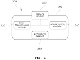
- FIG. 4 shows the configuration of the capsule endoscope.
- the capsule endoscope 300 has a housing 301 which forms the outward appearance, and a permanent magnet 310, a camera module 320, a data transmission module 330 and a power supply module 340 can be accommodated in the housing 301.
- the permanent magnet 310 forms magnetization in an arbitrary direction and provides a driving force of the capsule endoscope 300 by interaction with an external magnetic field.
- the camera module 320 is to obtain image information, and can be fixed and mounted on the front face, rear face or lateral face of the housing 301. In the meantime, in order to obtain accurate image information inside a living body through the camera module 320, a lighting device may be added.
- the data transmission module 330 serves to transmit the image information obtained from the camera module 320 to the outside.
- the power supply module 340 supplies actuating power necessary for the lighting device, and such a power supply module 340 can be provided by a battery.
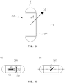
- FIG. 5 is a schematic diagram showing an outward appearance of the capsule endoscope.
- the capsule endoscope has an approximately elongated cylindrical shape and has a slope of a fixed angle ⁇ in the length direction v and the magnetization direction M.
- the magnetization direction M of the capsule endoscope 300 makes an acute angle (0 ⁇ 90°) with the length direction v.
- the capsule endoscope can carry out just precession at a stabilized position and cannot carry out translation by the external gradient magnetic field.
- FIGS. 6(a) and 6(b) show an example to make the capsule endoscope have magnetization in an arbitrary direction, and the capsule endoscope uses two permanent magnets 311 and 312 arranged at right angles to each other.
- the capsule endoscope 300 has magnetizations M1 and M2 and includes the two permanent magnets 311 and 312 arranged at right angles to each other. Such an arrangement of the permanent magnets is determined by the two magnetizations M1 and M2 to form magnetization M of a fixed angle to the length direction.
- the control unit 200 includes a control portion 220 which controls the sizes and directions of electric currents supplied to the first and second coil units 110 and 120 of the magnetic field generating portion 100 to control operation of the capsule endoscope 300.
- the control portion 220 controls operation of the coil driving portion 130 to control the direction of the gradient magnetic field of the second coil unit 120.
- control unit 200 includes a receiving portion 210 which receives an image signal transmitted from the capsule endoscope 300 and a power supply portion 230 for supplying an operation power of the control unit 200.
- first and second coil units 110 and 120 and the coil driving portion 130 are controlled by one control portion 220, but may be controlled by additional dedicated control modules according to speeds or properties of processing data.
- control unit may additionally include well-known peripheral devices, such as a capsule endoscope position tracking device which can track the position of the capsule endoscope using X rays, a display for outputting image information receiving from the receiving portion 210, or others.
- peripheral devices such as a capsule endoscope position tracking device which can track the position of the capsule endoscope using X rays, a display for outputting image information receiving from the receiving portion 210, or others.
- the capsule endoscope 300 by the rotating magnetic field generated from the fixed first coil unit 110 moves while carrying out precession and the spiral motion along the tubular organ by the gradient magnetic field generated by the second coil unit 120, and obtains necessary image information while moving.
- the operation of the capsule type endoscope system will be described in detail.
- the first coil unit 110 has the Helmholtz coils disposed on three axes which are at right angles to each other, and the second coil unit 120 has the Maxwell coils.
- the axial direction of the capsule endoscope is called v.
- a gradient magnetic field is generated using MC located on the v axis, a magnetic field having a slope size of g in the v-axis direction and a magnetic field having a slope of -0.5g in the radial direction are generated.
- M magnetization intensity of the magnet contained in the capsule endoscope
- V volume of the magnet
- g is a slope generated by MC
- ⁇ is an angle between the axial vector v and the magnetization intensity M.
- the capsule endoscope in such a condition carries out translation in the diagonal direction because a magnetic force F having a fixed angle with the v axis in a v-r plane, and the direction of the force (movement direction) will be changed by the magnetization direction through arrangement of the magnets of the capsule endoscope, namely, by ⁇ .
- v is a rotational central axis
- P is a normal vector (v-z plane) of the rotational central axis
- ⁇ is an angle between the vector v and the x-y plane when the vector v is projected onto the x-y plane
- ⁇ is an angle between the vector v and the x axis when the vector v is projected onto the x-y plane.
- the magnetization direction of the capsule endoscope rotates on the v axis, and when electric currents are applied to the Maxwell coils located on the v axis, the capsule endoscope generates a magnetic force in the v-axis direction and a magnetic force in the r-axis direction (See FIG. 7 ) at the same time.
- the capsule endoscope can carry out the spiral motion by the rotation and the diagonal translation.
- the magnetic field that must be generated from each Helmholtz coil for the precession of the capsule endoscope can be expressed by the following [Math formula 2].
- B c , x , t a cos ⁇ cos ⁇ + b ⁇ sin ⁇ cos ⁇ cos 2 ⁇ t + sin ⁇ sin 2 ⁇ t
- y , t a cos ⁇ sin ⁇ + b -sin ⁇ sin ⁇ cos 2 ⁇ t ⁇ cos ⁇ sin 2 ⁇ t
- B c , z , t a sin ⁇ + b cos ⁇ cos 2 ⁇ t
- a and b are Mcos ⁇ and Msin ⁇ , and ⁇ indicates rotational frequencies.
- the capsule endoscope can easily carry out the spiral motion just by controlling the intensity and the direction of the electric currents applied to the Maxwell coils.
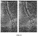
- FIG. 9 is a photograph showing an example of operation of the capsule type endoscope system according to the present invention.
- the permanent magnets come into contact with the wall surface of a glass tube by the rotating magnetic field and the gradient magnetic field generated from three pairs of the Helmholtz coils and a pair of the Maxwell coils so as to cause the spiral motion in the vertical direction.
Description
- The present invention relates to an operation control system of a capsule type endoscope and a capsule type endoscope system comprising the same, and more particularly, to an operation control system of a capsule type endoscope and a capsule type endoscope system comprising the same in which a capsule endoscope is driven to move along a tubular organ by a spiral motion, thereby being capable of making an accurate diagnosis of the wall of the tubular organ.
- A conventional flexible streamlined endoscope is inserted through a mouth or anus and controlled to diagnose ulcerative diseases of the inner wall of the digestive organs, and it causes a patient's suffering. To solve the problem, a capsule endoscopic, which has a form to easily enter into the digestive organs through the mouth and takes pictures of the inside of the digestive organs moves the inside of the digestive organs while moving the inside of the digestive organs by peristalsis of the digestive organs in order to make a diagnosis, has been developed.
- However, such a capsule endoscope has several disadvantages in that it is difficult to make an accurate diagnosis due to a passive movement by the peristalsis, and in that the capsule endoscope has a limited size because it must be inserted through the mouth so that it is difficult to mount various functional devices on the capsule endoscope.
- To solve these disadvantages, researches on an actuation mechanism for actuating the capsule endoscope using an electromagnetic actuation system have been conducted.
- Meanwhile, coil systems for actuating such a capsule endoscope have been proposed. For instance,
U.S. Patent Publication No. 2008/0272873 (hereafter, "prior art document") discloses a coil system for actuating a capsule endoscope. InU.S. Patent Publication No. 2008/0272873 , a total of 18 coils can be used to move the capsule endoscope in a certain direction. - However, the prior art coil system has a problem in that power consumption could be increased to move the capsule endoscope due to a high number of coils and each coil's role is not clearly defined.
- A capsule-type endoscope is inter alia disclosed in the
US 2011/316656 . DocumentUS 2011/301497 describes a capsule type endoscope system comprising a capsule endoscope and an operation control system of the capsule type endoscope with a first and second coil unit and a control unit. - Accordingly, the present invention has been made in an effort to solve the above-mentioned problems occurring in the prior arts, and it is the object of the present invention to provide a corresponding capsule type endoscope system with an operation control system of a capsule type endoscope to overcome those problems. By use of such a capsule type endoscope system the capsule endoscope can be driven to spirally move along a tubular organ to obtain image information, thereby being capable of making an accurate diagnosis of the wall of the tubular organ.
- It is another aspect of the present invention to provide an operation control system of a capsule type endoscope and a capsule type endoscope system comprising the same which can create a rotating magnetic field and a gradient magnetic field applied from the outside just by the minimum configuration of a coil system in order to realize a spiral motion of the capsule type endoscope, thereby simplifying the configuration of the entire system and being capable of making actuation control of the capsule type endoscope easy.
- It is a further aspect of the present invention to provide an operation control system of a capsule type endoscope and a capsule type endoscope system comprising the same which can make a spiral motion along the tubular organ by interaction between the rotating magnetic field and the gradient magnetic field generated from the outside.
- The object is achieved by a capsule type endoscope system with the features of independent claim 1.
- To achieve the above object the present invention provides an operation control system of a capsule type endoscope including: a first coil unit having coil portions which are fixed to three axes being at right angles to each other and generate magnetic fields in orthogonal axis directions, respectively; a second coil unit which is disposed to generate a gradient magnetic field in any direction relative to the magnetic field generated by the first coil unit; a coil driving portion for driving the second coil unit to adjust the orientation of the gradient magnetic field; and a control unit including a receiving portion which receives an image signal transmitted from a capsule endoscope and a control portion which controls electric currents supplied to the first and second coil units to adjust the generated magnetic field and controls operation of the coil driving portion.
- Preferably, in the present invention, the coil driving portion controls the second coil unit to perform three-dimensional rotation by independent biaxial rotations.
- Preferably, in the present invention, each coil portion of the first coil unit indues a Helmholtz coil.
- Preferably, in the present invention, the second coil unit includes a Maxwell coil.
- The present invention provides a capsule type endoscope system including a capsule endoscope which has magnetization inclined within a range of an acute angle (0<δ<90°) relative to the length direction of the housing of the endoscope and includes a camera module to capture an image and transmit the image to the outside.
- The present invention provides a capsule endoscope which is capable of carrying out movement by a spiral motion along the inside of a tubular organ by a rotating magnetic field and a gradient magnetic field generated from the outside, the capsule endoscope having magnetization inclined within a range of an acute angle (0<δ<90°) relative to the length direction of the housing of the endoscope and being capable of capturing an image and transmitting the image to the outside.
- As described above, the capsule type endoscope system according to the present invention can form the rotating magnetic field and the gradient magnetic field for the spiral motion of the capsule type endoscope just by the minimum coil system because including: the magnetic field forming portion which has the first coil unit disposed on three orthogonal axes to generate a magnetic field and a second coil unit having one coil structure for generating a gradient magnetic field; and a mechanical coil driving portion for three-dimensionally rotating the second coil unit to create the gradient magnetic field so that the rotating magnetic field and the gradient magnetic field are formed just by the minimum coil system, thereby simplifying the operation control system of the capsule type endoscope.
- The capsule type endoscope according to the present invention has magnetization characteristics to spirally move along the inside of the tubular organ by the rotating magnetic field and the gradient magnetic field generated from the outside.
-
-
FIG. 1 is a view showing the configuration of a capsule type endoscope system according to a preferred embodiment of the present invention. -
FIG. 2 is a view showing a first coil unit of the capsule type endoscope system according to the preferred embodiment of the present invention. -
FIG. 3 is a view showing a second coil unit and a coil driving portion of the capsule type endoscope system according to the preferred embodiment of the present invention. -
FIG. 4 is a view showing a capsule endoscope of the capsule type endoscope system according to the preferred embodiment of the present invention. -
FIGS. 5 and 6(a) and 6(b) are views showing a magnetization configuration of the capsule endoscope of the capsule type endoscope system according to the preferred embodiment of the present invention. -
FIG. 7 is a view explaining translation of the capsule endoscope of the capsule type endoscope system according to the preferred embodiment of the present invention. -
FIG. 8 is a view explaining precession of the capsule endoscope of the capsule type endoscope system according to the preferred embodiment of the present invention. -
FIG. 9 is a photograph showing an example of operation of the capsule type endoscope system according to the preferred embodiment of the present invention. - It should be appreciated that specific structures or functional explanations proposed in example embodiments of the present invention are to describe embodiments according to the concepts of the present invention and may be executed in various forms according to the concepts of the present invention. It should be understood, however, that there is no intent to limit example embodiments of the invention to the particular forms disclosed, but on the contrary, example embodiments of the invention are to cover all modifications, equivalents, and alternatives falling within the technical idea and scope of the present invention.
- It will be further understood that the words or terms used in the present invention are used to describe specific embodiments of the present invention and there is no intent to limit the present invention. The singular form of the components may be understood into the plural form unless otherwise specifically stated in the context. It should be also understood that the terms of 'include' or 'have' in the specification are used to mean that there are characteristics, numbers, steps, operations, components, parts, or combinations of the steps, operations, components and parts described in the specification and there is no intent to exclude existence or possibility of other characteristics, numbers, steps, operations, components, parts, or combinations of the steps, operations, components and parts.
- Hereinafter, reference will be now made in detail to the preferred embodiment of the present invention with reference to the attached drawings.
- Referring to
FIG. 1 , an operation control system of a capsule type endoscope according to a preferred embodiment of the present invention includes first andsecond coil units coil driving portion 130 for rotating the second coil unit 200 three-dimensionally, and a control unit 200 for receiving information transmitted from acapsule endoscope 300 and controlling power supply applied to the first andsecond coil units capsule endoscope 300 by a magnetic field. - The operation control system of the capsule type endoscope according to the present invention can perform precession of the
capsule endoscope 300 by a rotating magnetic field generated by thefirst coil unit 110 and a spiral motion that is carried out in contiguity with a tube wall when thecapsule endoscope 300 moves along the tubular digestive organ using momentum by a gradient magnetic field generated by thesecond coil unit 120. Hereinafter, each component will be described. - The
capsule endoscope 300 is controlled wirelessly by a magnetic field generated from a magneticfield generating portion 100 which includes the first andsecond coil units - As shown in
FIG. 2 , thefirst coil unit 110 hascoil portions - Not shown in the drawings, but it should be understood that supporting structures may be mounted to respectively fix the coil portions.
- The
coil portions x-axis coil portion 111, an y-axis coil portion 112 and a z-axis coil portion, and basically, each of thecoil portions - For example, Helmholtz coils or Maxwell coils may be used.
- Two Helmholtz coils form a pair. The two Helmholtz coils are spaced apart from each other as long as a radius on the central axis and can generate a uniform magnetic field when electric currents of the same size and direction are applied to the two coils.
- In the meantime, the Helmholtz coils can generate the uniform magnetic field depending on sizes or directions of electric currents applied to the two Helmholtz coils. Alternatively, combination of three Helmholtz coils may generate a rotating magnetic field, and it has been disclosed in
Korean Patent No. 10-1128034 which has been granted on March 12, 2012 - Two Maxwell coils form a pair. The two coils have a specific arrangement to generate a uniform gradient magnetic field when electric currents of the same size are applied to the two coils in the opposite directions.
- Meanwhile, preferably, the
first coil unit 110 uses the Helmholtz coils which are easy to be arranged on three axes to be at right angles to each other.FIG. 2 illustrates the first coil unit having the Helmholtz coils. - As described above, the three
coil portions -
FIG. 3 shows a preferred example of the second coil unit which can generate the gradient magnetic field, and the second coil unit is configured by coils which can generate the gradient magnetic field in one axis direction. - A pair of two coils which are arranged side by side form the coil unit for generating the gradient magnetic field. When electric currents applied to the two coils are in the opposite directions, the gradient magnetic field is generated. In the present invention, the second coil unit, preferably, uses the Maxwell coils.
- As shown in
FIG. 3 , thesecond coil unit 120 has a pair of the Maxwell coils 121, and the Maxwell coils 121 surround thefirst coil unit 110. - A gradient magnetic field is formed in the central axis direction of the Maxwell coils 121, and a gradient magnetic field which has an approximately linear slope is formed at the central portion.
- The
second coil unit 120 has thecoil driving portion 130 disposed as a mechanical structure which is capable of three-dimensionally driving with thefirst coil unit 110 as the center. - The
coil driving portion 130 can rotate thesecond coil unit 120 in certain two directions α and β, and hence, can control the direction of the gradient magnetic field generated from thesecond coil unit 120 into an arbitrary direction. - Particularly, the
second coil unit 120 which provides momentum for translation of the capsule endoscope uses just one coil structure and the direction of the gradient magnetic field can be adjusted using thecoil driving portion 130 which can rotate thesecond coil unit 120 three-dimensionally, so that the present invention can simplify the entire structure of the coil operation system for operating the capsule endoscope. - As shown in
FIG. 3 , thecoil driving portion 130 includes: avertical post 131 which is vertically fixed on the ground; arotating arm 132 which is horizontally disposed on thevertical post 131 to be able to rotate; and amovable arm 133 which fixes and supports thesecond coil unit 120 and is supported at the front end of therotating arm 132 so as to be able to move vertically. - Actuators, such as motors, which have been known, are mounted at the
rotating arm 132 which is rotatable on thevertical post 131 and themovable arm 133 which is vertically movable at the front end of therotating arm 132 so that the present invention can make an accurate operation control by electronic, hydraulic or pneumatic signals applied from the outside. - Preferably, the
movable arm 133 has an arc shape with a proper radius of curvature that makes thesecond coil unit 120 rotate three-dimensionally on the center of thesecond coil unit 120 which coincides with the center of the first coil unit and is a virtual rotation axis. - As described above, the
coil driving portion 130 can achieve the three-dimensional rotation because thesecond coil unit 120 can carry out biaxial rotation. Accordingly, the gradient magnetic field direction of thesecond coil unit 120 can be adjusted arbitrarily. - In this embodiment, the coil driving portion has a gimbal structure capable of carrying out the biaxial rotation, but the present invention is not limited to the above and can use various mechanical devices within the scope that the
second coil unit 120 can carry out the rotating motion three-dimensionally, such as a parallel mechanism (Stewart platform) or a robot arm. -
FIG. 4 shows the configuration of the capsule endoscope. Thecapsule endoscope 300 has ahousing 301 which forms the outward appearance, and apermanent magnet 310, acamera module 320, adata transmission module 330 and apower supply module 340 can be accommodated in thehousing 301. - The
permanent magnet 310 forms magnetization in an arbitrary direction and provides a driving force of thecapsule endoscope 300 by interaction with an external magnetic field. - The
camera module 320 is to obtain image information, and can be fixed and mounted on the front face, rear face or lateral face of thehousing 301. In the meantime, in order to obtain accurate image information inside a living body through thecamera module 320, a lighting device may be added. - The
data transmission module 330 serves to transmit the image information obtained from thecamera module 320 to the outside. - The
power supply module 340 supplies actuating power necessary for the lighting device, and such apower supply module 340 can be provided by a battery. -
FIG. 5 is a schematic diagram showing an outward appearance of the capsule endoscope. The capsule endoscope has an approximately elongated cylindrical shape and has a slope of a fixed angle δ in the length direction v and the magnetization direction M. Preferably, the magnetization direction M of thecapsule endoscope 300 makes an acute angle (0<δ<90°) with the length direction v. - It will be described in more detail later, but in the event that the magnetization direction coincides with the length direction, precession of the capsule endoscope by the external rotating magnetic field is not carried out. In the event that the magnetization direction is perpendicular to the length direction, the capsule endoscope can carry out just precession at a stabilized position and cannot carry out translation by the external gradient magnetic field.
-
FIGS. 6(a) and 6(b) show an example to make the capsule endoscope have magnetization in an arbitrary direction, and the capsule endoscope uses twopermanent magnets - As shown in
FIG. 6(a) , thecapsule endoscope 300 has magnetizations M1 and M2 and includes the twopermanent magnets - Referring to
FIG. 1 , the control unit 200 includes acontrol portion 220 which controls the sizes and directions of electric currents supplied to the first andsecond coil units field generating portion 100 to control operation of thecapsule endoscope 300. In this instance, thecontrol portion 220 controls operation of thecoil driving portion 130 to control the direction of the gradient magnetic field of thesecond coil unit 120. - Moreover, the control unit 200 includes a receiving
portion 210 which receives an image signal transmitted from thecapsule endoscope 300 and apower supply portion 230 for supplying an operation power of the control unit 200. - In this embodiment, the first and
second coil units coil driving portion 130 are controlled by onecontrol portion 220, but may be controlled by additional dedicated control modules according to speeds or properties of processing data. - Not mentioned in this embodiment in detail, but the control unit may additionally include well-known peripheral devices, such as a capsule endoscope position tracking device which can track the position of the capsule endoscope using X rays, a display for outputting image information receiving from the receiving
portion 210, or others. - In the capsule type endoscope system according to the present invention, the
capsule endoscope 300 by the rotating magnetic field generated from the fixedfirst coil unit 110 moves while carrying out precession and the spiral motion along the tubular organ by the gradient magnetic field generated by thesecond coil unit 120, and obtains necessary image information while moving. Hereinafter, the operation of the capsule type endoscope system will be described in detail. - In this embodiment, the
first coil unit 110 has the Helmholtz coils disposed on three axes which are at right angles to each other, and thesecond coil unit 120 has the Maxwell coils. - As shown in
FIG. 7 , the axial direction of the capsule endoscope is called v. When a gradient magnetic field is generated using MC located on the v axis, a magnetic field having a slope size of g in the v-axis direction and a magnetic field having a slope of -0.5g in the radial direction are generated. - In this instance, in the capsule endoscope, a magnetic force is generated by the gradient magnetic field, and the size of the magnetic force is obtained through the following [Math formula 1].

- In the math formula 1, M is magnetization intensity of the magnet contained in the capsule endoscope, V is volume of the magnet, g is a slope generated by MC, and δ is an angle between the axial vector v and the magnetization intensity M.
- As shown in
FIG. 7 , the capsule endoscope in such a condition carries out translation in the diagonal direction because a magnetic force F having a fixed angle with the v axis in a v-r plane, and the direction of the force (movement direction) will be changed by the magnetization direction through arrangement of the magnets of the capsule endoscope, namely, by δ. - Next, referring to
FIG. 8 , in order to make precession with the magnetization direction which is inclined at the angle δ because the central axis of the capsule endoscope is located on the v axis, it is necessary to properly determine the direction and the size of the magnetic field of the Helmholtz coils to generate a rotating magnetic field. - In
FIG. 8 , v is a rotational central axis, P is a normal vector (v-z plane) of the rotational central axis, ϕ is an angle between the vector v and the x-y plane when the vector v is projected onto the x-y plane, and θ is an angle between the vector v and the x axis when the vector v is projected onto the x-y plane. - Referring to
FIG. 8 , the magnetization direction of the capsule endoscope rotates on the v axis, and when electric currents are applied to the Maxwell coils located on the v axis, the capsule endoscope generates a magnetic force in the v-axis direction and a magnetic force in the r-axis direction (SeeFIG. 7 ) at the same time. By a resultant force of the two magnetic forces, the capsule endoscope can carry out the spiral motion by the rotation and the diagonal translation. - In the meantime, in order to make the capsule endoscope carry out the spiral motion along the tubular organ inside a three-dimensional space, the following must be satisfied.
- First, referring to
FIG. 8 , the magnetic field that must be generated from each Helmholtz coil for the precession of the capsule endoscope can be expressed by the following [Math formula 2].
- In the Math formula 2, a and b are Mcosδ and Msinδ, and ω indicates rotational frequencies.
- Next, the v axis and the Maxwell coils must be coincided with each other. When the v axis and the Maxwell coils are coincided with each other in direction, the capsule endoscope can easily carry out the spiral motion just by controlling the intensity and the direction of the electric currents applied to the Maxwell coils.
-
FIG. 9 is a photograph showing an example of operation of the capsule type endoscope system according to the present invention. InFIG. 9 , the permanent magnets come into contact with the wall surface of a glass tube by the rotating magnetic field and the gradient magnetic field generated from three pairs of the Helmholtz coils and a pair of the Maxwell coils so as to cause the spiral motion in the vertical direction. - It will be understood by those of ordinary skill in the art that there is no intent to limit example embodiments of the invention to the particular forms disclosed and that various changes, modifications and equivalences may be made therein without departing from the scope of the present invention as defined by the following claims.
| 110: | first coil unit | 111: | x-axis coil portion |
| 112: | y- |
113; | z-axis coil portion |
| 120: | second coil unit | 130: | coil driving portion |
| 131: | vertical post | 132: | rotating arm |
| 133: | movable arm | 200: | control unit |
| 210: | receiving portion | 220: | control portion |
| 300: | capsule endoscope | 301: | housing |
| 310: | permanent magnet | 320: | camera module |
| 330: | data transmission module | ||
| 340: | power supply module |
Claims (6)
- A capsule type endoscope system comprising a capsule endoscope (300) including a camera module (320) to capture an image and transmit the image to the outside and two permanent magnets (311, 312) which are placed in perpendicular to each other and form magnetization inclined within a range of an acute angle δ with 0° <δ<90° relative to a so called v-axis given by the length direction of the capsule endoscope (300); and
an operation control system (100, 200) comprising:a first coil unit (110) having three coil portions (111;112;113) which are fixed to three axes being at right angles to each other and generate magnetic fields in axis directions, respectively;a second coil unit (120) which is disposed to generate a gradient magnetic field in any direction relative to the magnetic field generated by the first coil unit;a coil driving portion (130) configured to drive the second coil unit (120) to adjust the orientation of the gradient magnetic field; anda control unit (200) including a receiving portion (210) configured to receive an image signal transmitted from the capsule endoscope and a control portion (220) configured to control electric currents supplied to the first and second coil units (110;120) to adjust the generated magnetic field and controls operation of the coil driving portion (130),characterized in thatthe operation control system (100, 200) is arranged to perform precession of the capsule endoscope (300) by rotating magnetic field generated by the first coil unit (110) and a spiral motion that is carried out in contiguity with a tube wall when the capsule endoscope (300) moves along a tubular organ using momentum by the gradient magnetic field generated by the second coil unit (120) added to said rotating magnetic field. - The capsule type endoscope system according to claim 1, wherein the coil driving portion (130) is configured to control the second coil unit (120) to perform three-dimensional rotation by independent biaxial rotations.
- The capsule type endoscope system according to claim 1, wherein each coil portion (111;112;113) of the first coil unit (110) includes a Helmholtz coil.
- The capsule type endoscope system according to claim 1, wherein the second coil unit (120) includes a Maxwell coil (121) .
- The capsule type endoscope system according to claim 4, wherein the Maxwell coils are located on the v-axis and wherein
the control portion (220) is arranged to control the intensity and the direction of the electric currents supplied to the second coil unit (120) such that the capsule endoscope (300) carries out the spiral motion. - The capsule type endoscope system according to one of claims 1 to 5,wherein the second coil unit (120) generates the gradient magnetic field using MC located on the v-axis, thereby generatinga magnetic field having a slope size of g in the v-axis direction, anda magnetic field having a slope of -0.5g in the radial direction.
Applications Claiming Priority (2)
| Application Number | Priority Date | Filing Date | Title |
|---|---|---|---|
| KR1020120133515A KR101410214B1 (en) | 2012-11-23 | 2012-11-23 | Capsule endoscope actuation control system, and a capsule endoscope system having the same |
| PCT/KR2013/010271 WO2014081150A1 (en) | 2012-11-23 | 2013-11-13 | Operation control system of capsule type endoscope, and capsule type endoscope system comprising same |
Publications (3)
| Publication Number | Publication Date |
|---|---|
| EP2923629A1 EP2923629A1 (en) | 2015-09-30 |
| EP2923629A4 EP2923629A4 (en) | 2016-08-17 |
| EP2923629B1 true EP2923629B1 (en) | 2022-04-20 |
Family
ID=50776280
Family Applications (1)
| Application Number | Title | Priority Date | Filing Date |
|---|---|---|---|
| EP13857619.4A Active EP2923629B1 (en) | 2012-11-23 | 2013-11-13 | Capsule type endoscope system |
Country Status (9)
| Country | Link |
|---|---|
| US (1) | US10123680B2 (en) |
| EP (1) | EP2923629B1 (en) |
| JP (1) | JP6207623B2 (en) |
| KR (1) | KR101410214B1 (en) |
| CN (1) | CN104822304B (en) |
| AU (1) | AU2013348680B2 (en) |
| IL (1) | IL238997B (en) |
| RU (1) | RU2626959C2 (en) |
| WO (1) | WO2014081150A1 (en) |
Families Citing this family (20)
| Publication number | Priority date | Publication date | Assignee | Title |
|---|---|---|---|---|
| CN106669040B (en) * | 2016-12-29 | 2019-08-23 | 臧大维 | Stereotaxis magnetic head and array, brain nervous cell electrical activity interference system |
| CN107049213A (en) * | 2017-03-28 | 2017-08-18 | 重庆金山医疗器械有限公司 | A kind of capsule endoscope control method and device |
| KR102061263B1 (en) * | 2017-07-21 | 2020-01-02 | 주식회사 우영메디칼 | System and method for controlling an electromagnetic coil system |
| KR102027249B1 (en) * | 2017-08-02 | 2019-10-01 | 주식회사 코프 | Medical imaging device |
| KR101853853B1 (en) * | 2017-11-29 | 2018-05-02 | 주식회사 인트로메딕 | An apparatus of capsule endoscopy, magnetic controller, and capsule endoscopy system |
| KR101884205B1 (en) | 2018-02-12 | 2018-08-01 | 주식회사 파워리퍼블릭 | Wireless power transmission type capsule endoscope with remote steering control |
| KR101969982B1 (en) * | 2018-03-19 | 2019-04-18 | 주식회사 엔도핀 | An apparatus of capsule endoscopy, magnetic controller, and capsule endoscopy system |
| WO2020014420A1 (en) * | 2018-07-12 | 2020-01-16 | Bionaut Labs Ltd. | Magnetic propulsion mechanism for magnetic devices |
| KR102228451B1 (en) | 2018-12-14 | 2021-03-17 | 가천대학교 산학협력단 | Optimum design method of gradient coil for electromagnetic drive device which control capsule endoscope from the outside, electromagnetic drive device using the same, and drive method therefor |
| CN109646052A (en) * | 2018-12-27 | 2019-04-19 | 华中科技大学鄂州工业技术研究院 | A kind of ultrasound capsule endoscope |
| KR102239107B1 (en) * | 2019-02-19 | 2021-04-13 | 전남대학교산학협력단 | Module type Capsule Endoscope capable of Disassembling and Assembling in the Digestive tract |
| CN109730625B (en) * | 2019-03-08 | 2021-08-10 | 大连理工大学 | Three-dimensional space voltage vector control method of space universal rotating magnetic field |
| KR102224828B1 (en) * | 2019-03-29 | 2021-03-09 | 전남대학교산학협력단 | Method for controlling motion of paramagnetism capsule endoscope |
| EP4058819A4 (en) * | 2019-11-13 | 2024-01-10 | California Inst Of Techn | Electromagnet gradient coil apparatus for micro-device localization |
| CA3160648A1 (en) * | 2019-11-15 | 2021-05-20 | Bionaut Labs Ltd. | System and method for remotely maneuvering a magnetic miniature device |
| CN112006778A (en) * | 2020-08-20 | 2020-12-01 | 广州大学 | Rotary cutting robot for cleaning thrombus |
| KR102595784B1 (en) * | 2020-11-11 | 2023-10-31 | 동국대학교 산학협력단 | Magnetically controlled, ph sensor-assisted navigation capsule endoscopy and control method thereof |
| CN112700942A (en) * | 2020-12-16 | 2021-04-23 | 苏州大学 | Electromagnetic field platform and control system with same |
| CN113229770A (en) * | 2021-03-25 | 2021-08-10 | 北京善行医疗科技有限公司 | Medical device guidance and control system and method |
| KR102652537B1 (en) * | 2021-09-16 | 2024-03-28 | 한양대학교 산학협력단 | Magnetic field generating module |
Citations (1)
| Publication number | Priority date | Publication date | Assignee | Title |
|---|---|---|---|---|
| US20110301497A1 (en) * | 2009-12-08 | 2011-12-08 | Magnetecs Corporation | Diagnostic and therapeutic magnetic propulsion capsule and method for using the same |
Family Cites Families (23)
| Publication number | Priority date | Publication date | Assignee | Title |
|---|---|---|---|---|
| US6330467B1 (en) * | 1999-02-04 | 2001-12-11 | Stereotaxis, Inc. | Efficient magnet system for magnetically-assisted surgery |
| CN1747679B (en) * | 2003-02-04 | 2012-10-03 | 奥林巴斯株式会社 | Medical apparatus guiding system and control method thereof |
| KR100972253B1 (en) | 2004-12-17 | 2010-07-23 | 올림푸스 가부시키가이샤 | Position-detection system for medical use using magnetic-induction |
| JP4679200B2 (en) | 2005-03-28 | 2011-04-27 | オリンパス株式会社 | Capsule type medical device position detection system, capsule type medical device guidance system, and capsule type medical device position detection method |
| DE102005010489B4 (en) | 2005-03-04 | 2007-02-01 | Siemens Ag | Coil system for non-contact magnetic navigation of a magnetic body in a patient located in a working space |
| CN1718152A (en) | 2005-06-29 | 2006-01-11 | 中国科学院合肥物质科学研究院 | Detector external magnetic field driving apparatus and method in the body |
| JP4823665B2 (en) * | 2005-12-02 | 2011-11-24 | オリンパスメディカルシステムズ株式会社 | Capsule type medical device and its guidance system |
| EP2384687B1 (en) * | 2005-12-27 | 2016-05-11 | Olympus Corporation | Encapsulated medical device guidance system |
| JP5101513B2 (en) * | 2006-09-14 | 2012-12-19 | オリンパスメディカルシステムズ株式会社 | Medical guidance system |
| JP4542560B2 (en) | 2007-04-05 | 2010-09-15 | オリンパス株式会社 | Capsule type medical device guidance system |
| KR100960289B1 (en) * | 2008-02-29 | 2010-06-07 | 한국항공대학교산학협력단 | Endoscope system |
| KR101001291B1 (en) | 2008-04-16 | 2010-12-14 | 전남대학교산학협력단 | Microrobot driving module and microrobot system actuated by electromagnetic manipulation |
| US8235888B2 (en) | 2008-07-08 | 2012-08-07 | Olympus Medical Systems Corp. | System for guiding capsule medical device |
| US8241206B2 (en) * | 2008-07-08 | 2012-08-14 | Olympus Medical Systems Corp. | System for guiding capsule medical device |
| RU80326U1 (en) * | 2008-08-20 | 2009-02-10 | Государственное образовательное учреждение высшего профессионального образования Томский политехнический университет | ENDOSCOPIC VIDEO CAPSULE |
| JP5096268B2 (en) | 2008-09-02 | 2012-12-12 | オリンパスメディカルシステムズ株式会社 | Capsule guidance system |
| DE102009013352B4 (en) * | 2009-03-16 | 2011-02-03 | Siemens Aktiengesellschaft | Coil arrangements for guiding a magnetic object in a working space |
| KR101084722B1 (en) * | 2009-06-18 | 2011-11-22 | 전남대학교산학협력단 | Three-dimension eletromagnetic drive device |
| US9044160B2 (en) * | 2009-08-21 | 2015-06-02 | Koninklijke Philips N.V. | Apparatus and method for generating and moving a magnetic field having a field free line |
| WO2011118253A1 (en) * | 2010-03-26 | 2011-09-29 | オリンパスメディカルシステムズ株式会社 | Capsule type medical device guidance system and method |
| KR101128034B1 (en) | 2010-09-13 | 2012-03-29 | 문행근 | Fillings of the stamps according to the soap stamping of the pattern by the mold and a method of manufacturing soap using the same |
| US20120149981A1 (en) * | 2010-12-08 | 2012-06-14 | Semion Khait | Magnetically maneuverable in-vivo device |
| WO2012090197A1 (en) * | 2010-12-30 | 2012-07-05 | Given Imaging Ltd. | System and method for automatic navigation of a capsule based on image stream captured in-vivo |
-
2012
- 2012-11-23 KR KR1020120133515A patent/KR101410214B1/en active IP Right Grant
-
2013
- 2013-11-13 US US14/646,542 patent/US10123680B2/en active Active
- 2013-11-13 JP JP2015543960A patent/JP6207623B2/en active Active
- 2013-11-13 AU AU2013348680A patent/AU2013348680B2/en active Active
- 2013-11-13 EP EP13857619.4A patent/EP2923629B1/en active Active
- 2013-11-13 RU RU2015124118A patent/RU2626959C2/en active
- 2013-11-13 WO PCT/KR2013/010271 patent/WO2014081150A1/en active Application Filing
- 2013-11-13 CN CN201380060906.6A patent/CN104822304B/en active Active
-
2015
- 2015-05-25 IL IL238997A patent/IL238997B/en active IP Right Grant
Patent Citations (1)
| Publication number | Priority date | Publication date | Assignee | Title |
|---|---|---|---|---|
| US20110301497A1 (en) * | 2009-12-08 | 2011-12-08 | Magnetecs Corporation | Diagnostic and therapeutic magnetic propulsion capsule and method for using the same |
Also Published As
| Publication number | Publication date |
|---|---|
| RU2626959C2 (en) | 2017-08-02 |
| KR101410214B1 (en) | 2014-06-20 |
| AU2013348680B2 (en) | 2017-03-02 |
| AU2013348680A1 (en) | 2015-07-09 |
| US10123680B2 (en) | 2018-11-13 |
| EP2923629A4 (en) | 2016-08-17 |
| EP2923629A1 (en) | 2015-09-30 |
| JP6207623B2 (en) | 2017-10-04 |
| US20150297065A1 (en) | 2015-10-22 |
| KR20140066372A (en) | 2014-06-02 |
| RU2015124118A (en) | 2017-01-10 |
| CN104822304A (en) | 2015-08-05 |
| JP2015535461A (en) | 2015-12-14 |
| IL238997A0 (en) | 2015-07-30 |
| IL238997B (en) | 2020-10-29 |
| WO2014081150A1 (en) | 2014-05-30 |
| CN104822304B (en) | 2017-12-01 |
Similar Documents
| Publication | Publication Date | Title |
|---|---|---|
| EP2923629B1 (en) | Capsule type endoscope system | |
| EP3515280B1 (en) | System and methoad for using a capsule device | |
| US10702132B2 (en) | System and method for using a capsule device | |
| US8771175B2 (en) | Capsule type endoscope including magnetic drive | |
| EP3539456B1 (en) | Apparatus for controlling the movement of a capsule endoscope in the digestive tract of a human body | |
| WO2007074888A1 (en) | Capsule type medical device guiding system and its control method | |
| JP2004298560A (en) | Capsule endoscope system | |
| KR101389439B1 (en) | Micro-robot system | |
| Liu et al. | Design of a magnetic actuated fully insertable robotic camera system for single-incision laparoscopic surgery | |
| JP5345241B2 (en) | Coil structure for guiding magnetic objects in the work space | |
| KR101256409B1 (en) | Actuation control system of capsule endoscope | |
| EP2561797B1 (en) | Micro robot system and capsule endoscope system for examining a tubular digestive system | |
| Guo et al. | Design and performance evaluation of the novel multi-modular capsule robot | |
| CN117642111A (en) | Magnetic field generating module and magnetic field generating device comprising same |
Legal Events
| Date | Code | Title | Description |
|---|---|---|---|
| PUAI | Public reference made under article 153(3) epc to a published international application that has entered the european phase |
Free format text: ORIGINAL CODE: 0009012 |
|
| 17P | Request for examination filed |
Effective date: 20150618 |
|
| AK | Designated contracting states |
Kind code of ref document: A1 Designated state(s): AL AT BE BG CH CY CZ DE DK EE ES FI FR GB GR HR HU IE IS IT LI LT LU LV MC MK MT NL NO PL PT RO RS SE SI SK SM TR |
|
| AX | Request for extension of the european patent |
Extension state: BA ME |
|
| DAX | Request for extension of the european patent (deleted) | ||
| RA4 | Supplementary search report drawn up and despatched (corrected) |
Effective date: 20160714 |
|
| RIC1 | Information provided on ipc code assigned before grant |
Ipc: A61B 1/00 20060101AFI20160708BHEP Ipc: A61B 1/04 20060101ALI20160708BHEP |
|
| STAA | Information on the status of an ep patent application or granted ep patent |
Free format text: STATUS: EXAMINATION IS IN PROGRESS |
|
| 17Q | First examination report despatched |
Effective date: 20170711 |
|
| STAA | Information on the status of an ep patent application or granted ep patent |
Free format text: STATUS: EXAMINATION IS IN PROGRESS |
|
| GRAP | Despatch of communication of intention to grant a patent |
Free format text: ORIGINAL CODE: EPIDOSNIGR1 |
|
| STAA | Information on the status of an ep patent application or granted ep patent |
Free format text: STATUS: GRANT OF PATENT IS INTENDED |
|
| INTG | Intention to grant announced |
Effective date: 20211123 |
|
| GRAS | Grant fee paid |
Free format text: ORIGINAL CODE: EPIDOSNIGR3 |
|
| GRAA | (expected) grant |
Free format text: ORIGINAL CODE: 0009210 |
|
| STAA | Information on the status of an ep patent application or granted ep patent |
Free format text: STATUS: THE PATENT HAS BEEN GRANTED |
|
| AK | Designated contracting states |
Kind code of ref document: B1 Designated state(s): AL AT BE BG CH CY CZ DE DK EE ES FI FR GB GR HR HU IE IS IT LI LT LU LV MC MK MT NL NO PL PT RO RS SE SI SK SM TR |
|
| REG | Reference to a national code |
Ref country code: GB Ref legal event code: FG4D |
|
| REG | Reference to a national code |
Ref country code: CH Ref legal event code: EP |
|
| REG | Reference to a national code |
Ref country code: IE Ref legal event code: FG4D |
|
| REG | Reference to a national code |
Ref country code: DE Ref legal event code: R096 Ref document number: 602013081472 Country of ref document: DE |
|
| REG | Reference to a national code |
Ref country code: AT Ref legal event code: REF Ref document number: 1484521 Country of ref document: AT Kind code of ref document: T Effective date: 20220515 |
|
| REG | Reference to a national code |
Ref country code: LT Ref legal event code: MG9D |
|
| REG | Reference to a national code |
Ref country code: NL Ref legal event code: MP Effective date: 20220420 |
|
| REG | Reference to a national code |
Ref country code: AT Ref legal event code: MK05 Ref document number: 1484521 Country of ref document: AT Kind code of ref document: T Effective date: 20220420 |
|
| PG25 | Lapsed in a contracting state [announced via postgrant information from national office to epo] |
Ref country code: NL Free format text: LAPSE BECAUSE OF FAILURE TO SUBMIT A TRANSLATION OF THE DESCRIPTION OR TO PAY THE FEE WITHIN THE PRESCRIBED TIME-LIMIT Effective date: 20220420 |
|
| PG25 | Lapsed in a contracting state [announced via postgrant information from national office to epo] |
Ref country code: SE Free format text: LAPSE BECAUSE OF FAILURE TO SUBMIT A TRANSLATION OF THE DESCRIPTION OR TO PAY THE FEE WITHIN THE PRESCRIBED TIME-LIMIT Effective date: 20220420 Ref country code: PT Free format text: LAPSE BECAUSE OF FAILURE TO SUBMIT A TRANSLATION OF THE DESCRIPTION OR TO PAY THE FEE WITHIN THE PRESCRIBED TIME-LIMIT Effective date: 20220822 Ref country code: NO Free format text: LAPSE BECAUSE OF FAILURE TO SUBMIT A TRANSLATION OF THE DESCRIPTION OR TO PAY THE FEE WITHIN THE PRESCRIBED TIME-LIMIT Effective date: 20220720 Ref country code: LT Free format text: LAPSE BECAUSE OF FAILURE TO SUBMIT A TRANSLATION OF THE DESCRIPTION OR TO PAY THE FEE WITHIN THE PRESCRIBED TIME-LIMIT Effective date: 20220420 Ref country code: HR Free format text: LAPSE BECAUSE OF FAILURE TO SUBMIT A TRANSLATION OF THE DESCRIPTION OR TO PAY THE FEE WITHIN THE PRESCRIBED TIME-LIMIT Effective date: 20220420 Ref country code: GR Free format text: LAPSE BECAUSE OF FAILURE TO SUBMIT A TRANSLATION OF THE DESCRIPTION OR TO PAY THE FEE WITHIN THE PRESCRIBED TIME-LIMIT Effective date: 20220721 Ref country code: FI Free format text: LAPSE BECAUSE OF FAILURE TO SUBMIT A TRANSLATION OF THE DESCRIPTION OR TO PAY THE FEE WITHIN THE PRESCRIBED TIME-LIMIT Effective date: 20220420 Ref country code: ES Free format text: LAPSE BECAUSE OF FAILURE TO SUBMIT A TRANSLATION OF THE DESCRIPTION OR TO PAY THE FEE WITHIN THE PRESCRIBED TIME-LIMIT Effective date: 20220420 Ref country code: BG Free format text: LAPSE BECAUSE OF FAILURE TO SUBMIT A TRANSLATION OF THE DESCRIPTION OR TO PAY THE FEE WITHIN THE PRESCRIBED TIME-LIMIT Effective date: 20220720 Ref country code: AT Free format text: LAPSE BECAUSE OF FAILURE TO SUBMIT A TRANSLATION OF THE DESCRIPTION OR TO PAY THE FEE WITHIN THE PRESCRIBED TIME-LIMIT Effective date: 20220420 |
|
| PG25 | Lapsed in a contracting state [announced via postgrant information from national office to epo] |
Ref country code: RS Free format text: LAPSE BECAUSE OF FAILURE TO SUBMIT A TRANSLATION OF THE DESCRIPTION OR TO PAY THE FEE WITHIN THE PRESCRIBED TIME-LIMIT Effective date: 20220420 Ref country code: PL Free format text: LAPSE BECAUSE OF FAILURE TO SUBMIT A TRANSLATION OF THE DESCRIPTION OR TO PAY THE FEE WITHIN THE PRESCRIBED TIME-LIMIT Effective date: 20220420 Ref country code: LV Free format text: LAPSE BECAUSE OF FAILURE TO SUBMIT A TRANSLATION OF THE DESCRIPTION OR TO PAY THE FEE WITHIN THE PRESCRIBED TIME-LIMIT Effective date: 20220420 Ref country code: IS Free format text: LAPSE BECAUSE OF FAILURE TO SUBMIT A TRANSLATION OF THE DESCRIPTION OR TO PAY THE FEE WITHIN THE PRESCRIBED TIME-LIMIT Effective date: 20220820 |
|
| REG | Reference to a national code |
Ref country code: DE Ref legal event code: R097 Ref document number: 602013081472 Country of ref document: DE |
|
| PG25 | Lapsed in a contracting state [announced via postgrant information from national office to epo] |
Ref country code: SM Free format text: LAPSE BECAUSE OF FAILURE TO SUBMIT A TRANSLATION OF THE DESCRIPTION OR TO PAY THE FEE WITHIN THE PRESCRIBED TIME-LIMIT Effective date: 20220420 Ref country code: SK Free format text: LAPSE BECAUSE OF FAILURE TO SUBMIT A TRANSLATION OF THE DESCRIPTION OR TO PAY THE FEE WITHIN THE PRESCRIBED TIME-LIMIT Effective date: 20220420 Ref country code: RO Free format text: LAPSE BECAUSE OF FAILURE TO SUBMIT A TRANSLATION OF THE DESCRIPTION OR TO PAY THE FEE WITHIN THE PRESCRIBED TIME-LIMIT Effective date: 20220420 Ref country code: EE Free format text: LAPSE BECAUSE OF FAILURE TO SUBMIT A TRANSLATION OF THE DESCRIPTION OR TO PAY THE FEE WITHIN THE PRESCRIBED TIME-LIMIT Effective date: 20220420 Ref country code: DK Free format text: LAPSE BECAUSE OF FAILURE TO SUBMIT A TRANSLATION OF THE DESCRIPTION OR TO PAY THE FEE WITHIN THE PRESCRIBED TIME-LIMIT Effective date: 20220420 Ref country code: CZ Free format text: LAPSE BECAUSE OF FAILURE TO SUBMIT A TRANSLATION OF THE DESCRIPTION OR TO PAY THE FEE WITHIN THE PRESCRIBED TIME-LIMIT Effective date: 20220420 |
|
| PLBE | No opposition filed within time limit |
Free format text: ORIGINAL CODE: 0009261 |
|
| STAA | Information on the status of an ep patent application or granted ep patent |
Free format text: STATUS: NO OPPOSITION FILED WITHIN TIME LIMIT |
|
| 26N | No opposition filed |
Effective date: 20230123 |
|
| PG25 | Lapsed in a contracting state [announced via postgrant information from national office to epo] |
Ref country code: AL Free format text: LAPSE BECAUSE OF FAILURE TO SUBMIT A TRANSLATION OF THE DESCRIPTION OR TO PAY THE FEE WITHIN THE PRESCRIBED TIME-LIMIT Effective date: 20220420 |
|
| PG25 | Lapsed in a contracting state [announced via postgrant information from national office to epo] |
Ref country code: SI Free format text: LAPSE BECAUSE OF FAILURE TO SUBMIT A TRANSLATION OF THE DESCRIPTION OR TO PAY THE FEE WITHIN THE PRESCRIBED TIME-LIMIT Effective date: 20220420 |
|
| PG25 | Lapsed in a contracting state [announced via postgrant information from national office to epo] |
Ref country code: MC Free format text: LAPSE BECAUSE OF FAILURE TO SUBMIT A TRANSLATION OF THE DESCRIPTION OR TO PAY THE FEE WITHIN THE PRESCRIBED TIME-LIMIT Effective date: 20220420 |
|
| REG | Reference to a national code |
Ref country code: CH Ref legal event code: PL |
|
| REG | Reference to a national code |
Ref country code: BE Ref legal event code: MM Effective date: 20221130 |
|
| PG25 | Lapsed in a contracting state [announced via postgrant information from national office to epo] |
Ref country code: LI Free format text: LAPSE BECAUSE OF NON-PAYMENT OF DUE FEES Effective date: 20221130 Ref country code: CH Free format text: LAPSE BECAUSE OF NON-PAYMENT OF DUE FEES Effective date: 20221130 |
|
| PG25 | Lapsed in a contracting state [announced via postgrant information from national office to epo] |
Ref country code: LU Free format text: LAPSE BECAUSE OF NON-PAYMENT OF DUE FEES Effective date: 20221113 |
|
| PG25 | Lapsed in a contracting state [announced via postgrant information from national office to epo] |
Ref country code: IE Free format text: LAPSE BECAUSE OF NON-PAYMENT OF DUE FEES Effective date: 20221113 |
|
| PG25 | Lapsed in a contracting state [announced via postgrant information from national office to epo] |
Ref country code: BE Free format text: LAPSE BECAUSE OF NON-PAYMENT OF DUE FEES Effective date: 20221130 |
|
| PGFP | Annual fee paid to national office [announced via postgrant information from national office to epo] |
Ref country code: GB Payment date: 20231123 Year of fee payment: 11 |
|
| PG25 | Lapsed in a contracting state [announced via postgrant information from national office to epo] |
Ref country code: IT Free format text: LAPSE BECAUSE OF FAILURE TO SUBMIT A TRANSLATION OF THE DESCRIPTION OR TO PAY THE FEE WITHIN THE PRESCRIBED TIME-LIMIT Effective date: 20220420 |
|
| PGFP | Annual fee paid to national office [announced via postgrant information from national office to epo] |
Ref country code: FR Payment date: 20231120 Year of fee payment: 11 Ref country code: DE Payment date: 20231127 Year of fee payment: 11 |
|
| PG25 | Lapsed in a contracting state [announced via postgrant information from national office to epo] |
Ref country code: HU Free format text: LAPSE BECAUSE OF FAILURE TO SUBMIT A TRANSLATION OF THE DESCRIPTION OR TO PAY THE FEE WITHIN THE PRESCRIBED TIME-LIMIT; INVALID AB INITIO Effective date: 20131113 |