EP2923351B1 - Method for bonding zircon or zirconia substrates - Google Patents
Method for bonding zircon or zirconia substrates Download PDFInfo
- Publication number
- EP2923351B1 EP2923351B1 EP13856812.6A EP13856812A EP2923351B1 EP 2923351 B1 EP2923351 B1 EP 2923351B1 EP 13856812 A EP13856812 A EP 13856812A EP 2923351 B1 EP2923351 B1 EP 2923351B1
- Authority
- EP
- European Patent Office
- Prior art keywords
- refractory
- bonded
- components
- substrate
- zircon
- Prior art date
- Legal status (The legal status is an assumption and is not a legal conclusion. Google has not performed a legal analysis and makes no representation as to the accuracy of the status listed.)
- Not-in-force
Links
Images


Classifications
-
- C—CHEMISTRY; METALLURGY
- C04—CEMENTS; CONCRETE; ARTIFICIAL STONE; CERAMICS; REFRACTORIES
- C04B—LIME, MAGNESIA; SLAG; CEMENTS; COMPOSITIONS THEREOF, e.g. MORTARS, CONCRETE OR LIKE BUILDING MATERIALS; ARTIFICIAL STONE; CERAMICS; REFRACTORIES; TREATMENT OF NATURAL STONE
- C04B37/00—Joining burned ceramic articles with other burned ceramic articles or other articles by heating
- C04B37/001—Joining burned ceramic articles with other burned ceramic articles or other articles by heating directly with other burned ceramic articles
-
- C—CHEMISTRY; METALLURGY
- C04—CEMENTS; CONCRETE; ARTIFICIAL STONE; CERAMICS; REFRACTORIES
- C04B—LIME, MAGNESIA; SLAG; CEMENTS; COMPOSITIONS THEREOF, e.g. MORTARS, CONCRETE OR LIKE BUILDING MATERIALS; ARTIFICIAL STONE; CERAMICS; REFRACTORIES; TREATMENT OF NATURAL STONE
- C04B35/00—Shaped ceramic products characterised by their composition; Ceramics compositions; Processing powders of inorganic compounds preparatory to the manufacturing of ceramic products
- C04B35/622—Forming processes; Processing powders of inorganic compounds preparatory to the manufacturing of ceramic products
- C04B35/64—Burning or sintering processes
- C04B35/645—Pressure sintering
-
- C—CHEMISTRY; METALLURGY
- C04—CEMENTS; CONCRETE; ARTIFICIAL STONE; CERAMICS; REFRACTORIES
- C04B—LIME, MAGNESIA; SLAG; CEMENTS; COMPOSITIONS THEREOF, e.g. MORTARS, CONCRETE OR LIKE BUILDING MATERIALS; ARTIFICIAL STONE; CERAMICS; REFRACTORIES; TREATMENT OF NATURAL STONE
- C04B2235/00—Aspects relating to ceramic starting mixtures or sintered ceramic products
- C04B2235/65—Aspects relating to heat treatments of ceramic bodies such as green ceramics or pre-sintered ceramics, e.g. burning, sintering or melting processes
- C04B2235/656—Aspects relating to heat treatments of ceramic bodies such as green ceramics or pre-sintered ceramics, e.g. burning, sintering or melting processes characterised by specific heating conditions during heat treatment
- C04B2235/6567—Treatment time
-
- C—CHEMISTRY; METALLURGY
- C04—CEMENTS; CONCRETE; ARTIFICIAL STONE; CERAMICS; REFRACTORIES
- C04B—LIME, MAGNESIA; SLAG; CEMENTS; COMPOSITIONS THEREOF, e.g. MORTARS, CONCRETE OR LIKE BUILDING MATERIALS; ARTIFICIAL STONE; CERAMICS; REFRACTORIES; TREATMENT OF NATURAL STONE
- C04B2235/00—Aspects relating to ceramic starting mixtures or sintered ceramic products
- C04B2235/70—Aspects relating to sintered or melt-casted ceramic products
- C04B2235/96—Properties of ceramic products, e.g. mechanical properties such as strength, toughness, wear resistance
- C04B2235/963—Surface properties, e.g. surface roughness
-
- C—CHEMISTRY; METALLURGY
- C04—CEMENTS; CONCRETE; ARTIFICIAL STONE; CERAMICS; REFRACTORIES
- C04B—LIME, MAGNESIA; SLAG; CEMENTS; COMPOSITIONS THEREOF, e.g. MORTARS, CONCRETE OR LIKE BUILDING MATERIALS; ARTIFICIAL STONE; CERAMICS; REFRACTORIES; TREATMENT OF NATURAL STONE
- C04B2237/00—Aspects relating to ceramic laminates or to joining of ceramic articles with other articles by heating
- C04B2237/30—Composition of layers of ceramic laminates or of ceramic or metallic articles to be joined by heating, e.g. Si substrates
- C04B2237/32—Ceramic
- C04B2237/34—Oxidic
- C04B2237/343—Alumina or aluminates
-
- C—CHEMISTRY; METALLURGY
- C04—CEMENTS; CONCRETE; ARTIFICIAL STONE; CERAMICS; REFRACTORIES
- C04B—LIME, MAGNESIA; SLAG; CEMENTS; COMPOSITIONS THEREOF, e.g. MORTARS, CONCRETE OR LIKE BUILDING MATERIALS; ARTIFICIAL STONE; CERAMICS; REFRACTORIES; TREATMENT OF NATURAL STONE
- C04B2237/00—Aspects relating to ceramic laminates or to joining of ceramic articles with other articles by heating
- C04B2237/30—Composition of layers of ceramic laminates or of ceramic or metallic articles to be joined by heating, e.g. Si substrates
- C04B2237/32—Ceramic
- C04B2237/34—Oxidic
- C04B2237/345—Refractory metal oxides
- C04B2237/348—Zirconia, hafnia, zirconates or hafnates
-
- C—CHEMISTRY; METALLURGY
- C04—CEMENTS; CONCRETE; ARTIFICIAL STONE; CERAMICS; REFRACTORIES
- C04B—LIME, MAGNESIA; SLAG; CEMENTS; COMPOSITIONS THEREOF, e.g. MORTARS, CONCRETE OR LIKE BUILDING MATERIALS; ARTIFICIAL STONE; CERAMICS; REFRACTORIES; TREATMENT OF NATURAL STONE
- C04B2237/00—Aspects relating to ceramic laminates or to joining of ceramic articles with other articles by heating
- C04B2237/50—Processing aspects relating to ceramic laminates or to the joining of ceramic articles with other articles by heating
- C04B2237/52—Pre-treatment of the joining surfaces, e.g. cleaning, machining
-
- C—CHEMISTRY; METALLURGY
- C04—CEMENTS; CONCRETE; ARTIFICIAL STONE; CERAMICS; REFRACTORIES
- C04B—LIME, MAGNESIA; SLAG; CEMENTS; COMPOSITIONS THEREOF, e.g. MORTARS, CONCRETE OR LIKE BUILDING MATERIALS; ARTIFICIAL STONE; CERAMICS; REFRACTORIES; TREATMENT OF NATURAL STONE
- C04B2237/00—Aspects relating to ceramic laminates or to joining of ceramic articles with other articles by heating
- C04B2237/50—Processing aspects relating to ceramic laminates or to the joining of ceramic articles with other articles by heating
- C04B2237/78—Side-way connecting, e.g. connecting two plates through their sides
-
- C—CHEMISTRY; METALLURGY
- C04—CEMENTS; CONCRETE; ARTIFICIAL STONE; CERAMICS; REFRACTORIES
- C04B—LIME, MAGNESIA; SLAG; CEMENTS; COMPOSITIONS THEREOF, e.g. MORTARS, CONCRETE OR LIKE BUILDING MATERIALS; ARTIFICIAL STONE; CERAMICS; REFRACTORIES; TREATMENT OF NATURAL STONE
- C04B2237/00—Aspects relating to ceramic laminates or to joining of ceramic articles with other articles by heating
- C04B2237/50—Processing aspects relating to ceramic laminates or to the joining of ceramic articles with other articles by heating
- C04B2237/80—Joining the largest surface of one substrate with a smaller surface of the other substrate, e.g. butt joining or forming a T-joint
Definitions
- the disclosure relates generally to methods for bonding refractory components together, without the use of a bonding agent, to form a larger refractory substrate.
- the refractory substrate may be useful in making refractory forming bodies for fusion down-drawn processes in the manufacture of high-precision glass substrates, such as liquid crystal displays (LCDs) and plasma displays.
- high-performance display devices such as liquid crystal and plasma displays
- liquid crystal and plasma displays typically employ two high-precision glass sheets, one as a substrate for the electronic circuit components and the other as a substrate for a color filter.
- the leading technology for making such high-quality glass substrates is the overflow fusion down-draw process, developed by Corning Incorporated, and described, e.g., in U.S. Patent Nos. 3,338,696 and 3,682,609 .
- the fusion down-draw process typically utilizes a forming body comprising an upper trough portion comprising two upper trough walls and a trough bottom and a lower portion having a wedge-shaped cross-section with two major side surfaces sloping downwardly to join at a root.
- the upper trough walls and the major side surfaces of the lower portion form two continuous forming surfaces which join at the root.
- molten glass is filled in the upper trough and allowed to overflow the top surfaces (or weirs) of the trough, down along the two forming surfaces, ultimately converging at the root to form a unitary glass ribbon with two pristine external surfaces that have not been exposed to the surface of the forming body.
- the ribbon is drawn down and cooled to form an elastic glass sheet having a desired thickness and a pristine surface quality.
- U.S. Patent No. 7,988,804 proposes methods for the manufacture of larger zircon blocks comprising bonding several smaller zircon components together using a bonding agent.
- these methods have resulted in a marked improvement in the industry, such methods still have certain drawbacks, such as decreased strength, incompatibility, corrosion, and streaking issues.
- the methods disclosed herein may provide larger refractory substrates without the aforementioned drawbacks.
- US 2012/196105 A1 discloses a method for making transparent ceramic spinel windows, domes and other complex shapes via edge bonding.
- EP 0362594 A1 discloses a method of joining two pre-sintered pieces of silicon carbide.
- EP 1829846 A1 discloses a method of joining beta-silicon carbide (SiC) pieces.
- JP2007 119262 discloses a method of manufacturing on alumina ceramic.
- a method for forming a refractory substrate comprises bonding together a plurality of refractory components chosen from the group consisting of zircon components and fused cast zirconia components, each component having at least one surface to be bonded, the method comprising (a) polishing each surface to be bonded to a surface roughness (R a ) of 200 nm or finer, (b) contacting the surfaces to be bonded to form an unbonded refractory substrate, (c) firing the unbonded refractory substrate, and (d) subjecting the surfaces to be bonded to a compressive force of from 650 kPa to 3500 kPa during firing, wherein the unbonded refractory substrate is fired for a time of at least 12 hours and at a temperature sufficient to sinter the refractory components and effect bonding at the surfaces.
- R a surface roughness
- the method comprises (a) preparing a refractory substrate by bonding together a plurality of refractory components according to the first aspect of the invention, and (b) machining the refractory substrate into a desired shape and dimension to form the refractory forming body.
- the unbonded refractory substrate is fired at a temperature and for a time sufficient to sinter the refractory components and effect bonding at the surfaces.
- a larger refractory substrate may be produced by bonding together at least two smaller refractory components, without the use of a bonding agent.
- two or more refractory components may be polished and/or otherwise prepared, brought into contact, and fired under a load, to produce a single refractory substrate.
- the methods of the instant disclosure may allow for the production of large-scale forming bodies, such as for the forming of glass substrates, without the increased costs associated with upgrading the required isostatic pressing equipment.
- the methods disclosed herein may provide an improvement over prior art methods at least because the instant methods do not require a bonding agent.
- Bonding agents typically require a chemical reaction to occur between their constituents and the refractory components to form an effective bond. If the reaction successfully proceeds to the point at which all of the bonding agent has reacted, a junction or joint comprising a thin layer of reactants will be formed between the refractory components. However, if the bonding agent is applied in a layer that is too thick, it may not completely react with the refractory material, thereby resulting in one or more intermediate phases that may compromise the strength of the bond. In addition, either the unreacted material or the expected reaction product might exhibit an enhanced or reduced corrosion by the molten glass during operation due to differential solubilities of the refractory or the reactants in the glass.
- FIG. 1 illustrates a backscattered electron image taken using a scanning electron microscope (SEM) of a failed bond between two zircon components using a bonding agent according to prior art methods.
- the bonding failure may, for example, have been the result of an anomalously thick layer of bonding agent.
- the zircon refractory material to be bonded 110 is shown on the right of the image.
- the bonding agent incompletely reacted with the zircon refractory 110 to form a mixture of zirconia-rich titania 120 and zirconium titanate 130.
- the presence of multiple bonding phases may result in weak bonding, phase incompatibility, and/or corrosion issues.
- a complete reaction and, thus, a more successful bonding would be indicated by a thin layer of titanium-rich zirconia 140, without the presence of the intermediate phases 120 and 130.
- a refractory substrate or forming body manufactured according to the methods of the instant disclosure may exhibit improved strength, such as MOR strength, due to the absence of a bonding agent joint.
- the refractory substrate or forming body may also have improved thermal shock properties, because there is no bonding agent and, thus, no difference in the thermal properties and/or behavior of the bonding agent and the refractory material, e.g. , during firing or operation.
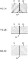
- FIGS. 2A and 2B illustrate two potentially problematic wear patterns associated with the use of a bonding agent.
- FIG. 2A two refractory components 210 and 220 are joined by a bonding agent 230.
- the bonding agent 230 has a higher solubility in glass, i.e., higher corrosion, than the refractory components 210 and 220.
- the bonded substrate in FIG. 2A will eventually, after time and use, develop a dip 240, which will cause streaking in the final glass product.
- FIG. 2B two refractory components 210 and 220 are joined by a bonding agent 230.
- the bonding agent 230 has a lower solubility in glass, i.e., lower corrosion, than the refractory components 210 and 220.
- the bonded substrate in FIG. 2B will eventually, after time and use, develop a ridge 250, which will cause streaking in the final glass product.
- FIG. 2C illustrates a refractory substrate manufactured according to the instant disclosure, i.e, without the use of a bonding agent.
- Refractory components 210 and 220 are joined without a bonding agent and do not exhibit an undesirable wear pattern such as a dip or a ridge.
- a joint 260 is present between the two components, but may not be visible or otherwise detectable. It is noted that the prior art methods can theoretically only achieve the corrosion profile of the instant disclosure when the bonding agent and the refractory components exhibit equal solubility in glass. Thus, by eliminating the joint caused by the presence of a bonding agent, glass forming bodies manufactured according to the instant methods may produce glass sheets with reduced streaking or, in certain embodiments, no streaking.
- the methods disclosed herein may be used to bond two or more components comprised of zircon or fused cast zirconia.
- the refractory components to be bonded together are zircon components.
- the refractory components may be different types of the same refractory, for instance the refractory materials may comprise the same major constituent, such as zircon, but may have different grain sizes or minor constituents.
- the refractory materials may be different types of zircon refractory, with various concentrations of other species that may improve certain refractory behavior, such as creep resistance and strength. The combination of different refractory materials or different types of refractory materials is not possible when using the unitary isopressing method.
- the refractory components to be bonded may be fired refractory bodies made by cold isostatically pressing inorganic refractory powders and various other ingredients and subsequently firing the resulting product.
- the refractory composition may comprise other starting materials conventionally utilized in ceramics, such as sintering aids and binders.
- the refractory components may, in certain embodiments, be fired zircon bodies.
- the refractory composition can contain, in addition to the major component(s), various minor components such as TiO 2, SiO 2, Fe 2 O 3 , Y 2 O 3 , B 2 O 3 , La 2 O 3 , BaO, Na 2 O, K 2 O, Li 2 O, CaO, and various other trace and minor components inherent to the raw materials.
- fired used interchangeably herein to denote a refractory composition that has been isostatically pressed and subjected to a temperature sufficient to sinter the refractory composition.
- the refractory components may have been fired at a temperature higher than about 1000°C, such as higher than about 1200°C, higher than about 1400°C, or higher than about 1500°C, before being bonded together according to the present disclosure.
- each refractory component comprises at least one surface to be bonded, also referred to herein as a bonding surface.
- each component will have a bonding surface and a distal surface. The bonding surfaces are joined together and the distal surfaces become the distal ends of the newly formed refractory substrate.
- the two end components will have a bonding surface and a distal surface and the middle component will have two bonding surfaces.
- the middle component is placed between the two end components, the bonding surfaces are joined together, and the distal surfaces become the distal ends of the newly formed refractory substrate.
- more than three components can be bonded together in the same fashion, by adding one or more additional middle components with two bonding surfaces in between the end components.
- the surfaces to be bonded are each ground and/or polished before coming into contact with one another.
- the surfaces are ground/and or polished using an abrasive with a grit size that is at least as fine as the largest particle present in the components to be bonded. For example, if the largest particle size in the component to be bonded is approximately 75 microns, then the surfaces to be bonded may be polished using a grit of about 75 microns or finer. Certain coarser surface finishes may be obtained by grinding the bonding surfaces without the need for finer polishing.
- the bonding surfaces may be polished using an abrasive with a grit size of about 35 microns or finer.
- the bonding surfaces may be polished using a grit of about 25 microns or finer, about 15 microns or finer, or about 10 microns or finer.
- the bonding surfaces may be polished using any technique known in the art, for instance, polishing with a diamond rouge or wheel or hand polishing with SiC paper.
- the surfaces may, for example be ground and/or polished with abrasives of varying grit sizes in descending order so as to achieve the desired surface roughness.
- the surfaces may be ground and/or milled using a grit size of about 50 microns, followed by polishing with a diamond rouge having a grit size of about 35 microns, followed by hand polishing with SiC paper having a grit size of 20 microns or finer.
- the surface roughness of the surface to be bonded may depend on various factors related to the polishing method. For instance, the grit size of the abrasive, the hardness of the abrasive, the hardness of the refractory component, and/or the load used during polishing may affect the final surface roughness obtained. As used herein, the term "surface roughness" is intended to denote the R a value, i.e., the average surface roughness.
- the surfaces to be bonded will be polished so as to obtain a surface roughness, R a , of less than about 200 nm. For example, the surface roughness may be less than about 150 nm, less than about 100 nm, less than about 50 nm, or less than about 10 nm.
- the surface roughness, R a can be imaged and calculated using methods well-known in the art, such as atomic force microscopy (AFM).
- FAM atomic force microscopy
- the surfaces to be bonded may, in certain embodiments, be machined, ground, and/or polished such that they are substantially complimentary to each other.
- each bonding surface is a mirror image of the opposite surface.
- two planar surfaces to be bonded will be parallel to each other. It should be understood however, that the surfaces to be bonded together need not be planar.
- the term "bonding surface pair" and variations thereof are used herein to denote two bonding surfaces that are brought into contact with each other. In the case where two refractory components are to be bonded together, the two bonding surfaces may be polished such that they are parallel to one another.
- the middle component may have two different bonding surfaces, one which is parallel to the bonding surface of a first end component and one which is parallel to the bonding surface of a second end component.
- various bonding surface pair configurations are possible and within the scope of the instant disclosure.
- the surfaces to be bonded may have surfaces that form an interlocking joint.
- the bonding surface of one component may have a protruding portion that fits substantially within a recessed portion of another bonding surface, such as a mortise and tenon joint.
- the bonding surfaces are polished and/or machined such that the corresponding surfaces of the joint are substantially parallel, to provide a fit that is substantially free of voids when the components are joined.
- various bonding surface pair configurations are possible, including interlocking joints which are identical or different. It is within the ability of one skilled in the art to select the bonding surface configuration suitable for a particular application.
- joint and other variations thereof is used herein to denote the interface at which two bonding surfaces are contacted and ultimately joined by firing under an applied compressive force.
- Prior art methods employing a bonding agent result in a visible or otherwise detectable joint comprising the bonding agent reactants.
- the "joint" of the instant application is not visible or otherwise detectable, as there is no bonding agent between the two components.
- the term “joint” as used herein may denote a theoretical line where two components are joined, but which is neither visible nor detectable. In some embodiments, the joint may be visible or detectable.
- the refractory components may be arranged by any means suitable to effect suitable contact between the surfaces to be bonded.
- the terms "direct contact,” “directly contacted,” and variations thereof are used interchangeably to denote that the surfaces to be bonded contact one another without any intervening component, i.e., in the absence of a bonding material or paste.
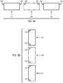
- the refractory components may be horizontally arranged in an end-to-end fashion such that the surfaces to be bonded are brought into direct contact.
- FIG. 3A which provides a non-limiting and exemplary horizontal configuration.
- two end components 310 are provided, each having a proximal end 320 containing a surface to be bonded and distal end 330 opposite the proximal end 320.
- the end components 310 are horizontally arranged in an end-to-end fashion, bringing the proximal ends 320 together such that the surfaces to be bonded are directly contacted.
- one or more middle components 340 are provided, each having two proximal ends 350 containing a surface to be bonded.
- the middle component 340 is placed between the end components 310, and the proximal ends 320 and 350 are brought together such that the surfaces to be bonded are directly contacted.
- the refractory components may be vertically arranged or stacked such that the surfaces to be bonded are brought into direct contact, as illustrated in FIG. 3B .
- two end components 310 are provided, each having a proximal end 320 containing a surface to be bonded and distal end 330 opposite the proximal end 320.
- the two end components 310 are vertically arranged by placing the proximal end 320 of one end component 310 over the proximal end 320 of another end component 310 such that the surfaces to be bonded are directly contacted.
- one or more middle components 340 are provided, each having two proximal ends 350 containing a surface to be bonded.
- the middle component 340 is placed between the end components 310, and the proximal ends 320 and 350 are brought together such that the surfaces to be bonded are directly contacted.
- the refractory components which may be contacted horizontally, vertically, or in any other fashion, form an unbonded refractory substrate which may then be fired under a load.
- the unbonded refractory substrate is subjected to a compressive force during firing.
- the compressive force may ensure good contact between the bonding surfaces so as to promote refractory crystal growth across the joint, which will yield a strong bond between the refractory components.
- the compressive force can be applied in various ways. In certain embodiments, the compressive force may be applied in a direction perpendicular to the surfaces to be bonded.
- the compressive force may be supplied by the force of gravity alone, i.e., by the weight of the top component(s).
- one or more weights may optionally be applied to a distal end of the unbonded substrate.
- gravity provides at least a part of the compressive force exerted on the surfaces to be bonded.
- a weight may be placed on the distal end so as to exert an additional pressure on the surfaces to be bonded of approximately 10 kPa.
- a compressive force may be applied via mechanical means, for instance, via an external hydraulic press.
- the total compressive force taking into account the weight of the top component(s) and any additionally applied weight and/or force, is sufficient to exert a total pressure on the surfaces to be bonded ranging from 650 kPa to 3,500 kPa, for example, from about 1,000 kPa to about 2,000 kPa.
- a compressive force may be applied to at least one of the distal ends of the substrate.
- a clamp, screw, or other suitable device may be used to apply a compressive force to at least one distal end of the substrate.
- the compressive force may be any force sufficient to promote adequate bonding at the surface interface.
- the compressive force is sufficient to exert a pressure on the surfaces to be bonded ranging from 650 kPa to 3,500 kPa, or from about 1,000 kPa to about 2,000 kPa.
- a weight or other mechanical device such as a clamp
- a weight or other mechanical device such as a clamp
- a weight or other mechanical device such as a clamp
- a thin piece of Pt foil may be placed between the substrate and the weight and/or device.
- the unbonded refractory substrate may be subjected to the compressive force either before it is placed in the furnace for firing or after it has been placed in the furnace, but before firing.
- the unbonded refractory substrate is then fired at a temperature and for a time sufficient to sinter the unbonded substrate and effect bonding between the individual refractory components at the bonding surfaces.
- the unbonded refractory substrate is fired at a temperature of at least about 1200°C for a time of at least about 12 hours.
- the firing temperature will vary depending on the refractory material and/or the desired length of the firing cycle.
- the unbonded substrate may be fired at a temperature of at least about 1500°C, at least about 1580°C, or at least about 1600°C.
- the unbonded refractory substrate may be fired at a temperature of at least about 1200°C, at least about 1300°C, or at least about 1400°C. It is within the ability of one skilled in the art to select the appropriate firing temperature based on the refractory material, firing time, and/or desired application.
- the unbonded refractory substrate is fired for time of at least about 12 hours, for example, at least about 20 hours, at least about 48 hours, at least about 60 hours, or at least about 120 hours.
- the bonded refractory substrate may have an MOR strength that is approximately equal to the MOR of an unbonded piece of the same refractory material. In other embodiments, the bonded refractory substrate may have an MOR strength that is higher than the MOR of an unbonded piece of the same refractory material. MOR strength may be determined, for example, by testing the refractory substrates using the four-point bending test, as set forth in ASTM C1674-11.
- the bonded refractory substrate may be subjected to post-bonding finishing to produce an end product, such as a forming body, trough, or any other desired ceramic article.
- post-bonding finishing may include, for example, machining, surface grinding, and/or polishing.
- the refractory substrate may be machined into any desired shape or size.
- the surfaces of the end product may optionally be further ground and/or polished to ensure a smooth surface over which glass can flow evenly.
- Other post-bonding finishing processes are envisioned by and within the scope of the instant disclosure.
- a forming body such as for use in the manufacture of glass substrates, may be manufactured according to the instant disclosure using various configurations of refractory components.
- refractory components 405 are horizontally contacted in an end-to-end fashion to form vertical joints 415, and the refractory substrate thus formed is subsequently machined into the shape of forming body 400.
- the machined forming body 400 comprises an upper trough 410, upper trough walls 420, a trough bottom 430, a bottom portion having a wedge-shaped cross-section 440, and two major side surfaces 450 sloping downardly to join at a root 460. Glass 470 flows over the trough walls 420, down the side surfaces 450 and converges at the root 460.
- refractory components 405 are placed side-by-side until a refractory substrate of the desired dimension is achieved.
- the joints are theoretically “visible” from the side view ( FIG. 4A ) and the top view ( FIG. 4B ), but not from the end view ( FIG. 4C ).
- One advantage of the vertical joint configuration is the ability to use smaller individual components. It should be noted that while FIGS. 4A-C illustrate a forming body 400 comprising five refractory components 405, with relatively evenly spaced and parallel vertical joints 415, this configuration is exemplary only. Any number of refractory components of varying sizes and with varying bonding surface configurations may be used in the manufacture of a forming body in accordance with the present disclosure.
- the forming body 500 may comprise a plurality of refractory components 505, which are vertically contacted to form horizontal joints 515.
- the proximal end of one refractory component is placed over a proximal end of another refractory component, with additional components being similarly vertically contacted until a refractory substrate of the desired dimension is achieved.
- the horizontal joint configuration may require relatively larger refractory components as compared to the vertical joint configuration, as the refractory components must have a length at least equal to the desired length of the forming body.
- the effect may be less noticeable when horizontal joint configuration is employed, at least because the effect will be spread out over the entire length of the surface upon which glass 570 flows. Any wear effect on the resulting glass sheet may thus be less detectable.
- FIGS. 5A-C illustrate a forming body 500 comprising three refractory components 505, with relatively evenly spaced and parallel horizontal joints 515 that intersect the forming body 500 at the trough bottom 530 and the bottom portion 540, this configuration is exemplary only. Any number of refractory components of varying sizes and with varying bonding surface configurations may be used in the manufacture of a forming body in accordance with the present disclosure and the horizontal joints may intersect the forming body at any location.
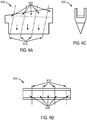
- FIGS. 6A-C illustrate a further embodiment of the disclosure, wherein a forming body 600 comprises a plurality of refractory components 605, which are horizontally contacted to form slanted joints 615.
- refractory components 605 are placed side-by-side, contacting the parallel slanted bonding surfaces, until a refractory substrate of the desired dimension is achieved.
- the joints are theoretically "visible" from the side view ( FIG. 6A ) and the top view ( FIG. 6B ), but not from the end view ( FIG. 6C ).
- FIGS. 6A-C illustrate a forming body 600 comprising five refractory components 605, with relatively evenly spaced slanted joints 615, which are each parallel to each other, this configuration is exemplary only. Any number of refractory components of varying sizes and with varying bonding surface configurations may be used in the manufacture of a forming body in accordance with the present disclosure.
- FIGS. 4-6 illustrate a forming body having a conventional shape
- any forming body of any varying shape or dimension may be produced from the bonded refractory substrates of the instant disclosure.
- any ceramic article, such as a trough, may be machined to any desired shape or size from a bonded refractory substrate of the instant disclosure.
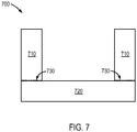
- FIG. 7 depicts a forehearth trough 700, which may be manufactured from several refractory components by bonding two trough walls 710 to a trough bottom 720. Joints 730 are formed where the trough walls 710 meet the trough bottom 720. It is to be understood that, while FIG. 7 illustrates two trough walls 710 arranged vertically on top of the trough bottom 720, it is also possible to horizontally arrange the trough bottom 720 between the trough walls 710. Other arrangements are envisioned and part of the instant disclosure.
- the forehearth trough configuration provides the advantage of a decreased number of joints while also providing savings in the time and costs associated with machining and a reduction in the potential for manufacturing defects, such as undesirable voids between the bonded refractory components.
- bonded zircon substrates were produced using various combinations of two different types of zircon (Zircon A and Zircon B).
- a zircon substrate was produced from two fired zircon components having an approximate dimension of 11.43 cm x 5.08 cm x 3.81 cm.
- the bonding surface (the 11.43 cm x 3.81 cm side) of each block was polished using a diamond wheel followed by hand polishing with SiC papers having progressively finer grits, beginning with a P360 grit (40.5 microns), followed by P800 (25.8 microns) and P1200 (15.3 microns). After polishing, the components were ultrasonically cleaned for approximately 15 minutes and dried overnight in a drying oven operating at about 120°C.
- the zircon components were vertically stacked, a thin piece of Pt foil and a weight of approximately 20 g were placed on top (on a distal end) of the stacked components, and the unbonded substrates thus formed were fired at approximately 1580°C. No bonding material was used between the two zircon components.
- the firing time varied among the tested samples.
- the Zircon A-A substrate was fired for about 12 hours, the Zircon A-B substrate was fired for about 48 hours, and the Zircon B-B substrate was fired for about 120 hours.
- the resulting bonded zircon substrates were then machined to produce approximately 10 smaller substrates of substantially identical dimension (approximately 1.27 cm x 0.63 cm x 11.43 cm), each having the bonded joint at approximately the midpoint of the length (11.43 cm) of the substrate.
- the machined substrates were then subjected to a four-point bending test at room temperature.
- the MOR strength of the bonded zircon substrates was compared to the MOR of unbonded zircon substrates made of Zircon A and Zircon B and having approximately the same dimension as the bonded zircon substrates.
- Table I below provides the results of the MOR four-point bending test.
- the bonded Zircon B-B substrate fired for approximately 120 hours, demonstrated an MOR strength higher than that of either the unbonded Zircon A or Zircon B substrate.
- the bonded Zircon A-B substrate fired for about 48 hours, demonstrated an MOR strength approximately equal to that of the unbonded Zircon A and Zircon B substrate.
- the firing time may affect the MOR strength of the resulting bonded substrate.
- a longer firing time may result in a stronger bond.
- Table I Average MOR Strength Zircon A Zircon B Zircon B-B 1580°C 120 hrs Zircon A-B 1580°C 48 hrs Zircon A-A 1580°C 12 hrs Average MOR Strength (MPa) 132.0 130.8 135.6 126.7 89.3
- Table II shows a summary of the location of the failure (breaking point) for each bonded zircon substrate tested.
- the Zircon A-A samples demonstrated not only the lowest MOR strength, but also all of the failures in Zircon A-A occurred at the bond, rather than in the substrate.
- Table II Location of Failure of Bonded Substrates Zircon B-B 1580°C, 120 hrs Zircon A-B 1580°C, 48 hrs Zircon A-A 1580°C, 12 hrs Number of Failures at Bond 2 7 9 Number of Failures at Substrate 7 5 (failure in substrate A) 0 Total Number of Samples 9 12 9
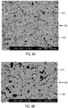
- FIG. 8A shows an SEM image (magnification x200) of a bonded pair of zircon components 810 and 820 (Zircon A-A), polished using a diamond wheel followed by polishing with diamond film having a grit size of approximately 35 microns, and fired at approximately 1580°C for about 48 hours, without the use of a bonding agent.
- the joint between the two components is shown with a dotted line 830. Without the addition of this line to the SEM image, it is very difficult to see the joint of the two separate pieces of zircon, even under magnification.
- the zircon grains have grown across the interface, resulting in a microstructure that is substantially uniform across the boundary.
- FIG. 8B shows a higher magnification SEM image (magnification x750) of the same sample. Again, the joint between the two components 810 and 820 is illustrated by a dotted line 830. Larger single grains located on both sides of the line indicate that grain growth has occurred at the interface of the two substrates, forming a strong bond.
- FIG. 9A shows an SEM image (magnification x200) of a bonded pair of zircon components 910 and 920 (Zircon A-A), polished using a diamond wheel followed by polishing with diamond films having progressively finer grits (approximately 35, 9, 6, and 3 microns), and fired at approximately 1580°C for about 48 hours, without the use of a bonding agent.
- the joint between the two components is shown with a dotted line 930. Without the addition of this line to the SEM image, it is very difficult to see the joint of the two separate pieces of zircon, even under magnification.
- the zircon grains have grown across the interface, resulting in a microstructure that is substantially uniform across the boundary.
- FIG. 9B shows a higher magnification SEM image (magnification x750) of the same sample.
- the joint between the two components 910 and 920 is illustrated by a dotted line 930.
- Grain growth has occurred across the interface of the two substrates and can easily be seen as larger single grains that are located on both sides of the line. Grain growth at the interface indicates the formation of a strong bond. It is noted that the grain growth across the interface appears to be more pronounced in FIG. 9B (3 micron grit) than in FIG. 8B (35 micron grit).
- surface roughness is reduced by polishing with a finer grit, which increases the degree of contact between the surfaces to be bonded, which in turn increases the degree of grain growth across the interface.
Description
- The disclosure relates generally to methods for bonding refractory components together, without the use of a bonding agent, to form a larger refractory substrate. The refractory substrate may be useful in making refractory forming bodies for fusion down-drawn processes in the manufacture of high-precision glass substrates, such as liquid crystal displays (LCDs) and plasma displays.
- Currently marketed high-performance display devices, such as liquid crystal and plasma displays, typically employ two high-precision glass sheets, one as a substrate for the electronic circuit components and the other as a substrate for a color filter. The leading technology for making such high-quality glass substrates is the overflow fusion down-draw process, developed by Corning Incorporated, and described, e.g., in
U.S. Patent Nos. 3,338,696 and3,682,609 . - The fusion down-draw process typically utilizes a forming body comprising an upper trough portion comprising two upper trough walls and a trough bottom and a lower portion having a wedge-shaped cross-section with two major side surfaces sloping downwardly to join at a root. The upper trough walls and the major side surfaces of the lower portion form two continuous forming surfaces which join at the root. During operation, molten glass is filled in the upper trough and allowed to overflow the top surfaces (or weirs) of the trough, down along the two forming surfaces, ultimately converging at the root to form a unitary glass ribbon with two pristine external surfaces that have not been exposed to the surface of the forming body. The ribbon is drawn down and cooled to form an elastic glass sheet having a desired thickness and a pristine surface quality.
- Consumer demand for high-performance displays with ever growing size and image quality requirements poses a challenge in terms of the manufacturing processes employed to produce large pristine glass sheets. The larger the glass substrate, the larger the forming body must be to manufacture the substrate. Traditionally, forming bodies are formed by cold isostatically pressing a single, unitary piece of refractory material, such as zircon. Understandably, larger isostatic presses are required to make larger forming bodies from a unitary refractory material. However, when taking into account the size reduction caused by the shrinkage of the green refractory during firing and the subsequent machining of the refractory substrate to produce the forming body, the size of the isopress required can become significantly greater as the desired size of the forming body increases. The high capital investment in such large isopresses may be cost-prohibitive, especially for larger glass substrates, such as Gen-10 (2850x3050 mm) and above.
- Thus, there is a need in the industry for efficient and cost-effective processes for making larger refractory substrates from which larger forming bodies can be machined.
U.S. Patent No. 7,988,804 proposes methods for the manufacture of larger zircon blocks comprising bonding several smaller zircon components together using a bonding agent. However, while these methods have resulted in a marked improvement in the industry, such methods still have certain drawbacks, such as decreased strength, incompatibility, corrosion, and streaking issues. The methods disclosed herein may provide larger refractory substrates without the aforementioned drawbacks. -
US 2012/196105 A1 discloses a method for making transparent ceramic spinel windows, domes and other complex shapes via edge bonding.EP 0362594 A1 discloses a method of joining two pre-sintered pieces of silicon carbide.EP 1829846 A1 discloses a method of joining beta-silicon carbide (SiC) pieces.JP2007 119262 - In a first aspect of the invention, there is provided a method for forming a refractory substrate according to claim 1. In particular, the method comprises bonding together a plurality of refractory components chosen from the group consisting of zircon components and fused cast zirconia components, each component having at least one surface to be bonded, the method comprising (a) polishing each surface to be bonded to a surface roughness (Ra) of 200 nm or finer, (b) contacting the surfaces to be bonded to form an unbonded refractory substrate, (c) firing the unbonded refractory substrate, and (d) subjecting the surfaces to be bonded to a compressive force of from 650 kPa to 3500 kPa during firing, wherein the unbonded refractory substrate is fired for a time of at least 12 hours and at a temperature sufficient to sinter the refractory components and effect bonding at the surfaces.
- In a second aspect of the invention, there is provided a method for making a refractory forming body as defined in claim 8. In particular, the method comprises (a) preparing a refractory substrate by bonding together a plurality of refractory components according to the first aspect of the invention, and (b) machining the refractory substrate into a desired shape and dimension to form the refractory forming body. In certain embodiments, the unbonded refractory substrate is fired at a temperature and for a time sufficient to sinter the refractory components and effect bonding at the surfaces.
- Additional features and advantages will be set forth in the detailed description which follows, and in part will be readily apparent to those skilled in the art from the description or recognized by practicing the embodiments as described in the written description and claims hereof, as well as the appended drawings. It is to be understood that both the foregoing general description and the following detailed description are merely exemplary, and are intended to provide an overview or framework to understand the nature and character of the claims.
- The accompanying drawings are included to provide a further understanding of the disclosure, and are incorporated in and constitute a part of this specification. The drawings illustrate one or more exemplary embodiments and, together with the description, serve to explain the principles and operation of the various embodiments.
-
Figure 1 is is a backscattered electron image of two zircon components bonded together using a prior art method. -
Figure 2A is a graphic representation of two refractory components bonded together using a prior art method -
Figure 2B is a graphic representation of two refractory components bonded together using a prior art method. -
Figure 2C is a graphic representation of two refractory components bonded together using a method according to the disclosure. -
Figure 3A is a graphic representation of two or more refractory compmonents to be bonded together using a method according to the disclosure. -
Figure 3B is a graphic representation of two or more refractory components to be bonded together using a method according to the disclosure. -
Figure 4A is a side view of a forming body manufactured using a method according to the disclosure. -
Figure 4B is a top view of a forming body manufactured using a method according to the disclosure. -
Figure 4C is an end view of a forming body manufactured using a method according to the disclosure. -
Figure 5A is a side view of a forming body manufactured using a method according to the disclosure. -
Figure 5B is a top view of a forming body manufactured using a method according to the disclosure. -
Figure 5C is an end view of a forming body manufactured using a method according to the disclosure. -
Figure 6A is a side view of a forming body manufactured using a method according to the disclosure. -
Figure 6B is a top view of a forming body manufactured using a method according to the disclosure. -
Figure 6C is an end view of a forming body manufactured using a method according to the disclosure. -
Figure 7 is an end view of a forming body manufactured using a method according to the disclosure. -
Figure 8A is a backscattered electron image of two zircon components bonded together using a method according to the disclosure. -
Figure 8B is a backscattered electron image of two zircon components bonded together using a method according to the disclosure. -
Figure 9A is a backscattered electron image of two zircon components bonded together using a method according to the disclosure. -
Figure 9B is a backscattered electron image of two zircon components bonded together using a method according to the disclosure. - According to various embodiments of the disclosure, a larger refractory substrate may be produced by bonding together at least two smaller refractory components, without the use of a bonding agent. For example, two or more refractory components may be polished and/or otherwise prepared, brought into contact, and fired under a load, to produce a single refractory substrate. Thus, the methods of the instant disclosure may allow for the production of large-scale forming bodies, such as for the forming of glass substrates, without the increased costs associated with upgrading the required isostatic pressing equipment. While the instant disclosure envisions the manufacture of forming bodies for the production of larger glass substrates such as Gen-10 and above, it should be noted that the methods disclosed herein may also be used for the manufacture of smaller glass substrates, such as Gen-8 (2200x2500 mm) and below, which could otherwise be manufactured using the unitary isopressing approach.
- The methods disclosed herein may provide an improvement over prior art methods at least because the instant methods do not require a bonding agent. Bonding agents typically require a chemical reaction to occur between their constituents and the refractory components to form an effective bond. If the reaction successfully proceeds to the point at which all of the bonding agent has reacted, a junction or joint comprising a thin layer of reactants will be formed between the refractory components. However, if the bonding agent is applied in a layer that is too thick, it may not completely react with the refractory material, thereby resulting in one or more intermediate phases that may compromise the strength of the bond. In addition, either the unreacted material or the expected reaction product might exhibit an enhanced or reduced corrosion by the molten glass during operation due to differential solubilities of the refractory or the reactants in the glass.
-
FIG. 1 illustrates a backscattered electron image taken using a scanning electron microscope (SEM) of a failed bond between two zircon components using a bonding agent according to prior art methods. The bonding failure may, for example, have been the result of an anomalously thick layer of bonding agent. The zircon refractory material to be bonded 110 is shown on the right of the image. The bonding agent incompletely reacted with the zircon refractory 110 to form a mixture of zirconia-rich titania 120 andzirconium titanate 130. The presence of multiple bonding phases may result in weak bonding, phase incompatibility, and/or corrosion issues. A complete reaction and, thus, a more successful bonding would be indicated by a thin layer of titanium-rich zirconia 140, without the presence of theintermediate phases - Without wishing to be bound by theory, it is believed that the instant methods may reduce or even eliminate compatibility and/or corrosion issues because the molten glass will contact only the refractory material, without the presence of a distinct bonding agent phase. Furthermore, a refractory substrate or forming body manufactured according to the methods of the instant disclosure may exhibit improved strength, such as MOR strength, due to the absence of a bonding agent joint. In certain embodiments, the refractory substrate or forming body may also have improved thermal shock properties, because there is no bonding agent and, thus, no difference in the thermal properties and/or behavior of the bonding agent and the refractory material, e.g., during firing or operation.
- Another potential problem associated with the use of bonding agents is varying glass corrosion behavior. For example, if the joint material corrodes more or less readily than the refractory material during operation, the resulting glass sheet may have streak lines or thickness band variations.
FIGS. 2A and 2B illustrate two potentially problematic wear patterns associated with the use of a bonding agent. - In
FIG. 2A , tworefractory components bonding agent 230. In this case, thebonding agent 230 has a higher solubility in glass, i.e., higher corrosion, than therefractory components FIG. 2A will eventually, after time and use, develop adip 240, which will cause streaking in the final glass product. InFIG. 2B , tworefractory components bonding agent 230. In this case, thebonding agent 230 has a lower solubility in glass, i.e., lower corrosion, than therefractory components FIG. 2B will eventually, after time and use, develop aridge 250, which will cause streaking in the final glass product. - In contrast,
FIG. 2C illustrates a refractory substrate manufactured according to the instant disclosure, i.e, without the use of a bonding agent.Refractory components - The methods disclosed herein may be used to bond two or more components comprised of zircon or fused cast zirconia. According to one embodiment, the refractory components to be bonded together are zircon components. In other non-limiting embodiments, the refractory components may be different types of the same refractory, for instance the refractory materials may comprise the same major constituent, such as zircon, but may have different grain sizes or minor constituents. By way of non-limiting example, the refractory materials may be different types of zircon refractory, with various concentrations of other species that may improve certain refractory behavior, such as creep resistance and strength. The combination of different refractory materials or different types of refractory materials is not possible when using the unitary isopressing method.
- According to various embodiments, the refractory components to be bonded may be fired refractory bodies made by cold isostatically pressing inorganic refractory powders and various other ingredients and subsequently firing the resulting product. The refractory composition may comprise other starting materials conventionally utilized in ceramics, such as sintering aids and binders. The refractory components may, in certain embodiments, be fired zircon bodies. The refractory composition can contain, in addition to the major component(s), various minor components such as TiO2, SiO2, Fe2O3, Y2O3, B2O3, La2O3, BaO, Na2O, K2O, Li2O, CaO, and various other trace and minor components inherent to the raw materials.
- The terms "fired," "fired body," "fired component," and other variations thereof are used interchangeably herein to denote a refractory composition that has been isostatically pressed and subjected to a temperature sufficient to sinter the refractory composition. For example, the refractory components may have been fired at a temperature higher than about 1000°C, such as higher than about 1200°C, higher than about 1400°C, or higher than about 1500°C, before being bonded together according to the present disclosure.
- According to various embodiments, each refractory component comprises at least one surface to be bonded, also referred to herein as a bonding surface. For instance, in the case of bonding two refractory components, each component will have a bonding surface and a distal surface. The bonding surfaces are joined together and the distal surfaces become the distal ends of the newly formed refractory substrate. When more than two refractory components are bonded together, such as three components, the two end components will have a bonding surface and a distal surface and the middle component will have two bonding surfaces. The middle component is placed between the two end components, the bonding surfaces are joined together, and the distal surfaces become the distal ends of the newly formed refractory substrate. Likewise, more than three components can be bonded together in the same fashion, by adding one or more additional middle components with two bonding surfaces in between the end components.
- The surfaces to be bonded are each ground and/or polished before coming into contact with one another. In certain embodiments, the surfaces are ground/and or polished using an abrasive with a grit size that is at least as fine as the largest particle present in the components to be bonded. For example, if the largest particle size in the component to be bonded is approximately 75 microns, then the surfaces to be bonded may be polished using a grit of about 75 microns or finer. Certain coarser surface finishes may be obtained by grinding the bonding surfaces without the need for finer polishing.
- According to various embodiments, the bonding surfaces may be polished using an abrasive with a grit size of about 35 microns or finer. For example, the bonding surfaces may be polished using a grit of about 25 microns or finer, about 15 microns or finer, or about 10 microns or finer. The bonding surfaces may be polished using any technique known in the art, for instance, polishing with a diamond rouge or wheel or hand polishing with SiC paper. The surfaces may, for example be ground and/or polished with abrasives of varying grit sizes in descending order so as to achieve the desired surface roughness. By way of non-limiting example, the surfaces may be ground and/or milled using a grit size of about 50 microns, followed by polishing with a diamond rouge having a grit size of about 35 microns, followed by hand polishing with SiC paper having a grit size of 20 microns or finer.
- The surface roughness of the surface to be bonded may depend on various factors related to the polishing method. For instance, the grit size of the abrasive, the hardness of the abrasive, the hardness of the refractory component, and/or the load used during polishing may affect the final surface roughness obtained. As used herein, the term "surface roughness" is intended to denote the Ra value, i.e., the average surface roughness. The surfaces to be bonded will be polished so as to obtain a surface roughness, Ra, of less than about 200 nm. For example, the surface roughness may be less than about 150 nm, less than about 100 nm, less than about 50 nm, or less than about 10 nm. The surface roughness, Ra, can be imaged and calculated using methods well-known in the art, such as atomic force microscopy (AFM). Without wishing to be bound by theory, it is believed that the degree of contact between the surfaces to bonded increases as the surfaces are ground and/or polished to a finer finish, thus resulting in a stronger bond between the components.
- The surfaces to be bonded may, in certain embodiments, be machined, ground, and/or polished such that they are substantially complimentary to each other. In other words, in this embodiment, each bonding surface is a mirror image of the opposite surface. For example, two planar surfaces to be bonded will be parallel to each other. It should be understood however, that the surfaces to be bonded together need not be planar. The term "bonding surface pair" and variations thereof are used herein to denote two bonding surfaces that are brought into contact with each other. In the case where two refractory components are to be bonded together, the two bonding surfaces may be polished such that they are parallel to one another. In the case where three components are to be bonded together, the middle component may have two different bonding surfaces, one which is parallel to the bonding surface of a first end component and one which is parallel to the bonding surface of a second end component. In this embodiment, there are two bonding surface pairs, which may have identical or different configurations. Likewise, when more than three components are bonded together, various bonding surface pair configurations are possible and within the scope of the instant disclosure.
- In another embodiment, the surfaces to be bonded may have surfaces that form an interlocking joint. By way of non-limiting example, the bonding surface of one component may have a protruding portion that fits substantially within a recessed portion of another bonding surface, such as a mortise and tenon joint. In this embodiment, the bonding surfaces are polished and/or machined such that the corresponding surfaces of the joint are substantially parallel, to provide a fit that is substantially free of voids when the components are joined. As discussed above, when bonding three or more components, various bonding surface pair configurations are possible, including interlocking joints which are identical or different. It is within the ability of one skilled in the art to select the bonding surface configuration suitable for a particular application.
- The term "joint" and other variations thereof is used herein to denote the interface at which two bonding surfaces are contacted and ultimately joined by firing under an applied compressive force. Prior art methods employing a bonding agent result in a visible or otherwise detectable joint comprising the bonding agent reactants. However, in certain embodiments, the "joint" of the instant application is not visible or otherwise detectable, as there is no bonding agent between the two components. Thus, the term "joint" as used herein may denote a theoretical line where two components are joined, but which is neither visible nor detectable. In some embodiments, the joint may be visible or detectable.
- The refractory components may be arranged by any means suitable to effect suitable contact between the surfaces to be bonded. As used herein, the terms "direct contact," "directly contacted," and variations thereof are used interchangeably to denote that the surfaces to be bonded contact one another without any intervening component, i.e., in the absence of a bonding material or paste.
- The refractory components may be horizontally arranged in an end-to-end fashion such that the surfaces to be bonded are brought into direct contact. This embodiment is illustrated in
FIG. 3A , which provides a non-limiting and exemplary horizontal configuration. In the case of two components to be bonded, twoend components 310 are provided, each having aproximal end 320 containing a surface to be bonded anddistal end 330 opposite theproximal end 320. Theend components 310 are horizontally arranged in an end-to-end fashion, bringing the proximal ends 320 together such that the surfaces to be bonded are directly contacted. Optionally, in the case of three or more components to be bonded, one or moremiddle components 340 are provided, each having twoproximal ends 350 containing a surface to be bonded. Themiddle component 340 is placed between theend components 310, and the proximal ends 320 and 350 are brought together such that the surfaces to be bonded are directly contacted. - In another embodiment, the refractory components may be vertically arranged or stacked such that the surfaces to be bonded are brought into direct contact, as illustrated in
FIG. 3B . In the case of two components to be bonded, twoend components 310 are provided, each having aproximal end 320 containing a surface to be bonded anddistal end 330 opposite theproximal end 320. The twoend components 310 are vertically arranged by placing theproximal end 320 of oneend component 310 over theproximal end 320 of anotherend component 310 such that the surfaces to be bonded are directly contacted. In the case of three or more components to be bonded, one or moremiddle components 340 are provided, each having twoproximal ends 350 containing a surface to be bonded. Themiddle component 340 is placed between theend components 310, and the proximal ends 320 and 350 are brought together such that the surfaces to be bonded are directly contacted. - The refractory components which may be contacted horizontally, vertically, or in any other fashion, form an unbonded refractory substrate which may then be fired under a load. According to various embodiments, the unbonded refractory substrate is subjected to a compressive force during firing. Without wishing to be bound by theory, it is believed that the compressive force may ensure good contact between the bonding surfaces so as to promote refractory crystal growth across the joint, which will yield a strong bond between the refractory components. The compressive force can be applied in various ways. In certain embodiments, the compressive force may be applied in a direction perpendicular to the surfaces to be bonded.
- By way of non-limiting example, when the refractory components are vertically stacked to form an unbonded refractory substrate, the compressive force may be supplied by the force of gravity alone, i.e., by the weight of the top component(s). In another embodiment, one or more weights may optionally be applied to a distal end of the unbonded substrate. In this embodiment, gravity provides at least a part of the compressive force exerted on the surfaces to be bonded. For example, a weight may be placed on the distal end so as to exert an additional pressure on the surfaces to be bonded of approximately 10 kPa. Alternatively, a compressive force may be applied via mechanical means, for instance, via an external hydraulic press. According to the invention, the total compressive force, taking into account the weight of the top component(s) and any additionally applied weight and/or force, is sufficient to exert a total pressure on the surfaces to be bonded ranging from 650 kPa to 3,500 kPa, for example, from about 1,000 kPa to about 2,000 kPa.
- In another embodiment, when the refractory components are arranged in an end-to-end horizontal fashion to form an unbonded refractory substrate, a compressive force may be applied to at least one of the distal ends of the substrate. For example, a clamp, screw, or other suitable device may be used to apply a compressive force to at least one distal end of the substrate. The compressive force may be any force sufficient to promote adequate bonding at the surface interface. In certain embodiments, the compressive force is sufficient to exert a pressure on the surfaces to be bonded ranging from 650 kPa to 3,500 kPa, or from about 1,000 kPa to about 2,000 kPa.
- When a weight or other mechanical device such as a clamp is applied to one or both distal ends of the unbonded refractory substrate it may be desirable, in certain embodiments, to place a chemically inert or non-reactive material between the substrate and the weight and/or device. By way of non-limiting example, a thin piece of Pt foil may be placed between the substrate and the weight and/or device.
- The unbonded refractory substrate may be subjected to the compressive force either before it is placed in the furnace for firing or after it has been placed in the furnace, but before firing. The unbonded refractory substrate is then fired at a temperature and for a time sufficient to sinter the unbonded substrate and effect bonding between the individual refractory components at the bonding surfaces. According to various embodiments, the unbonded refractory substrate is fired at a temperature of at least about 1200°C for a time of at least about 12 hours. The firing temperature, according to various embodiments, will vary depending on the refractory material and/or the desired length of the firing cycle.
- For example, in the case of zircon components, the unbonded substrate may be fired at a temperature of at least about 1500°C, at least about 1580°C, or at least about 1600°C. In other cases, such as in the case of alumina components, the unbonded refractory substrate may be fired at a temperature of at least about 1200°C, at least about 1300°C, or at least about 1400°C. It is within the ability of one skilled in the art to select the appropriate firing temperature based on the refractory material, firing time, and/or desired application. The unbonded refractory substrate is fired for time of at least about 12 hours, for example, at least about 20 hours, at least about 48 hours, at least about 60 hours, or at least about 120 hours.
- After firing is complete, the refractory components should be bonded together to form a unitary refractory substrate. In some embodiments, the bonded refractory substrate may have an MOR strength that is approximately equal to the MOR of an unbonded piece of the same refractory material. In other embodiments, the bonded refractory substrate may have an MOR strength that is higher than the MOR of an unbonded piece of the same refractory material. MOR strength may be determined, for example, by testing the refractory substrates using the four-point bending test, as set forth in ASTM C1674-11.
- In certain embodiments, the bonded refractory substrate may be subjected to post-bonding finishing to produce an end product, such as a forming body, trough, or any other desired ceramic article. Such post-bonding finishing may include, for example, machining, surface grinding, and/or polishing. The refractory substrate may be machined into any desired shape or size. The surfaces of the end product may optionally be further ground and/or polished to ensure a smooth surface over which glass can flow evenly. Other post-bonding finishing processes are envisioned by and within the scope of the instant disclosure.
- A forming body, such as for use in the manufacture of glass substrates, may be manufactured according to the instant disclosure using various configurations of refractory components. For example, in the embodiment illustrated in
FIGS. 4A-C ,refractory components 405 are horizontally contacted in an end-to-end fashion to formvertical joints 415, and the refractory substrate thus formed is subsequently machined into the shape of formingbody 400. The machined formingbody 400 comprises anupper trough 410,upper trough walls 420, atrough bottom 430, a bottom portion having a wedge-shapedcross-section 440, and twomajor side surfaces 450 sloping downardly to join at aroot 460.Glass 470 flows over thetrough walls 420, down the side surfaces 450 and converges at theroot 460. - In this embodiment,
refractory components 405 are placed side-by-side until a refractory substrate of the desired dimension is achieved. When a forming body is machined from a refractory substrate thus formed, the joints are theoretically "visible" from the side view (FIG. 4A ) and the top view (FIG. 4B ), but not from the end view (FIG. 4C ). One advantage of the vertical joint configuration is the ability to use smaller individual components. It should be noted that whileFIGS. 4A-C illustrate a formingbody 400 comprising fiverefractory components 405, with relatively evenly spaced and parallelvertical joints 415, this configuration is exemplary only. Any number of refractory components of varying sizes and with varying bonding surface configurations may be used in the manufacture of a forming body in accordance with the present disclosure. - In another embodiment, as illustrated in
FIGS. 5A-C , the formingbody 500 may comprise a plurality ofrefractory components 505, which are vertically contacted to formhorizontal joints 515. In this embodiment, the proximal end of one refractory component is placed over a proximal end of another refractory component, with additional components being similarly vertically contacted until a refractory substrate of the desired dimension is achieved. When a forming body is machined from a refractory substrate thus formed, the joints are theoretically "visible" from the side view (FIG. 5A ) and the end view (FIG. 5C ), but not from the top view (FIG. 5B ). - The horizontal joint configuration may require relatively larger refractory components as compared to the vertical joint configuration, as the refractory components must have a length at least equal to the desired length of the forming body. However, in the case of joint wear and/or corrosion after a length of use, the effect may be less noticeable when horizontal joint configuration is employed, at least because the effect will be spread out over the entire length of the surface upon which
glass 570 flows. Any wear effect on the resulting glass sheet may thus be less detectable. It should be noted that, whileFIGS. 5A-C illustrate a formingbody 500 comprising threerefractory components 505, with relatively evenly spaced and parallelhorizontal joints 515 that intersect the formingbody 500 at thetrough bottom 530 and thebottom portion 540, this configuration is exemplary only. Any number of refractory components of varying sizes and with varying bonding surface configurations may be used in the manufacture of a forming body in accordance with the present disclosure and the horizontal joints may intersect the forming body at any location. -
FIGS. 6A-C illustrate a further embodiment of the disclosure, wherein a formingbody 600 comprises a plurality ofrefractory components 605, which are horizontally contacted to form slanted joints 615. In this embodiment,refractory components 605 are placed side-by-side, contacting the parallel slanted bonding surfaces, until a refractory substrate of the desired dimension is achieved. When a forming body is machined from a refractory substrate thus formed, the joints are theoretically "visible" from the side view (FIG. 6A ) and the top view (FIG. 6B ), but not from the end view (FIG. 6C ). - Similar to the horizontal joint configuration, any potential joint wear and/or corrosion will produce a less noticeable effect because the effect will be spread out over a larger area of the forming body and, thus, the resulting glass sheet. The slanted joint configuration may also allow for the use of relatively smaller refractory components. It should be noted that, while
FIGS. 6A-C illustrate a formingbody 600 comprising fiverefractory components 605, with relatively evenly spaced slantedjoints 615, which are each parallel to each other, this configuration is exemplary only. Any number of refractory components of varying sizes and with varying bonding surface configurations may be used in the manufacture of a forming body in accordance with the present disclosure. - While
FIGS. 4-6 illustrate a forming body having a conventional shape, it is to be understood that any forming body of any varying shape or dimension may be produced from the bonded refractory substrates of the instant disclosure. Still further, any ceramic article, such as a trough, may be machined to any desired shape or size from a bonded refractory substrate of the instant disclosure. - For instance,
FIG. 7 depicts aforehearth trough 700, which may be manufactured from several refractory components by bonding twotrough walls 710 to atrough bottom 720.Joints 730 are formed where thetrough walls 710 meet thetrough bottom 720. It is to be understood that, whileFIG. 7 illustrates twotrough walls 710 arranged vertically on top of thetrough bottom 720, it is also possible to horizontally arrange thetrough bottom 720 between thetrough walls 710. Other arrangements are envisioned and part of the instant disclosure. The forehearth trough configuration provides the advantage of a decreased number of joints while also providing savings in the time and costs associated with machining and a reduction in the potential for manufacturing defects, such as undesirable voids between the bonded refractory components. - Various embodiments will be further clarified by the following non-limiting examples.
- Several bonded zircon substrates were produced using various combinations of two different types of zircon (Zircon A and Zircon B). In each case, a zircon substrate was produced from two fired zircon components having an approximate dimension of 11.43 cm x 5.08 cm x 3.81 cm. The bonding surface (the 11.43 cm x 3.81 cm side) of each block was polished using a diamond wheel followed by hand polishing with SiC papers having progressively finer grits, beginning with a P360 grit (40.5 microns), followed by P800 (25.8 microns) and P1200 (15.3 microns). After polishing, the components were ultrasonically cleaned for approximately 15 minutes and dried overnight in a drying oven operating at about 120°C. The zircon components were vertically stacked, a thin piece of Pt foil and a weight of approximately 20 g were placed on top (on a distal end) of the stacked components, and the unbonded substrates thus formed were fired at approximately 1580°C. No bonding material was used between the two zircon components.
- The firing time varied among the tested samples. The Zircon A-A substrate was fired for about 12 hours, the Zircon A-B substrate was fired for about 48 hours, and the Zircon B-B substrate was fired for about 120 hours. The resulting bonded zircon substrates were then machined to produce approximately 10 smaller substrates of substantially identical dimension (approximately 1.27 cm x 0.63 cm x 11.43 cm), each having the bonded joint at approximately the midpoint of the length (11.43 cm) of the substrate. The machined substrates were then subjected to a four-point bending test at room temperature. The MOR strength of the bonded zircon substrates was compared to the MOR of unbonded zircon substrates made of Zircon A and Zircon B and having approximately the same dimension as the bonded zircon substrates.
- Table I below provides the results of the MOR four-point bending test. The bonded Zircon B-B substrate, fired for approximately 120 hours, demonstrated an MOR strength higher than that of either the unbonded Zircon A or Zircon B substrate. Similarly, the bonded Zircon A-B substrate, fired for about 48 hours, demonstrated an MOR strength approximately equal to that of the unbonded Zircon A and Zircon B substrate. The bonded Zircon A-A substrate, fired for about 12 hours, demonstrated an acceptable MOR strength; however, the measured MOR strength was less than that of the unbondend Zircon A and Zircon B substrates. Thus, without wishing to be bound by theory, it is possible that the firing time may affect the MOR strength of the resulting bonded substrate. In some embodiments, a longer firing time may result in a stronger bond.
Table I: Average MOR Strength Zircon A Zircon B Zircon B-B 1580° C 120 hrsZircon A-B 1580°C 48 hrs Zircon A-A 1580°C 12 hrs Average MOR Strength (MPa) 132.0 130.8 135.6 126.7 89.3 - Table II shows a summary of the location of the failure (breaking point) for each bonded zircon substrate tested. The Zircon A-A samples demonstrated not only the lowest MOR strength, but also all of the failures in Zircon A-A occurred at the bond, rather than in the substrate.
Table II: Location of Failure of Bonded Substrates Zircon B-B 1580°C, 120 hrs Zircon A-B 1580°C, 48 hrs Zircon A-A 1580°C, 12 hrs Number of Failures at Bond 2 7 9 Number of Failures at Substrate 7 5 (failure in substrate A) 0 Total Number of Samples 9 12 9 -
FIG. 8A shows an SEM image (magnification x200) of a bonded pair ofzircon components 810 and 820 (Zircon A-A), polished using a diamond wheel followed by polishing with diamond film having a grit size of approximately 35 microns, and fired at approximately 1580°C for about 48 hours, without the use of a bonding agent. The joint between the two components is shown with adotted line 830. Without the addition of this line to the SEM image, it is very difficult to see the joint of the two separate pieces of zircon, even under magnification. The zircon grains have grown across the interface, resulting in a microstructure that is substantially uniform across the boundary. -
FIG. 8B shows a higher magnification SEM image (magnification x750) of the same sample. Again, the joint between the twocomponents line 830. Larger single grains located on both sides of the line indicate that grain growth has occurred at the interface of the two substrates, forming a strong bond. -
FIG. 9A shows an SEM image (magnification x200) of a bonded pair ofzircon components 910 and 920 (Zircon A-A), polished using a diamond wheel followed by polishing with diamond films having progressively finer grits (approximately 35, 9, 6, and 3 microns), and fired at approximately 1580°C for about 48 hours, without the use of a bonding agent. The joint between the two components is shown with adotted line 930. Without the addition of this line to the SEM image, it is very difficult to see the joint of the two separate pieces of zircon, even under magnification. The zircon grains have grown across the interface, resulting in a microstructure that is substantially uniform across the boundary. -
FIG. 9B shows a higher magnification SEM image (magnification x750) of the same sample. Again, the joint between the twocomponents line 930. Grain growth has occurred across the interface of the two substrates and can easily be seen as larger single grains that are located on both sides of the line. Grain growth at the interface indicates the formation of a strong bond. It is noted that the grain growth across the interface appears to be more pronounced inFIG. 9B (3 micron grit) than inFIG. 8B (35 micron grit). Without wishing to be bound by theory, it is believed that surface roughness is reduced by polishing with a finer grit, which increases the degree of contact between the surfaces to be bonded, which in turn increases the degree of grain growth across the interface. - Unless otherwise expressly stated, it is in no way intended that any method set forth herein be construed as requiring that its steps be performed in a specific order. Accordingly, where a method claim does not actually recite an order to be followed by its steps or it is not otherwise specifically stated in the claims or descriptions that the steps are to be limited to a specific order, it is no way intended that any particular order be inferred.
Claims (8)
- A method for bonding together a plurality of refractory components (310; 405; 505; 605), each having at least one surface to be bonded (320), the method comprising:(a) polishing each surface to be bonded (320) to a surface roughness Ra of 200 nm or finer;(b) directly contacting the surfaces to be bonded (320) to form an unbonded refractory substrate;(c) firing the unbonded refractory substrate;(d) subjecting the surfaces to be bonded to a compressive force during firing; andwherein the plurality of refractory components (310; 405; 505; 605) are chosen from the group consisting of zircon components and fused cast zirconia components, and wherein the unbonded refractory substrate is fired for a time of at least 12 hours and at a temperature sufficient to sinter the plurality of refractory components (310; 405; 505; 605) and effect bonding at the surfaces,
characterised in that the compressive force is from 650 kPa to 3500 kPa. - The method of claim 1, wherein the surfaces to be bonded (320) are polished to a surface roughness Ra of 100 nm or finer.
- The method of claim 1 or claim 2, wherein the surfaces to be bonded (320) are milled, ground, and/or polished such that the surfaces to be bonded (320) are substantially complimentary to each other.
- The method of claim 1, wherein the plurality of refractory components (310; 405; 505; 605) have interlocking surfaces to be bonded (320).
- The method of any one of claims 1 - 4, wherein the compressive force is applied in a direction perpendicular to the surfaces to be bonded (320).
- The method of any one of claims 1 - 5, wherein at least a first refractory component and a second refractory component of the plurality of refractory components (310; 405; 505; 605) are bonded together, each of the first and second refractory components having a proximal end (320) containing a surface to be bonded and a distal end (330) opposite the proximal end;
the proximal end of the first refractory component is placed vertically over the proximal end (320) of the second refractory component such that the surfaces to be bonded are directly contacted;
optionally, one or more third refractory components (340) of the plurality of refractory components, each having two proximal ends (350) containing a surface to be bonded, are placed between the first and second refractory components (310) such that the surfaces to be bonded are directly contacted; and
the compressive force is applied to at least the distal end (330) of the first refractory component. - The method of any one of claims 1 - 5, wherein at least a first refractory component and a second refractory component of the plurality of refractory components (310; 405; 505; 605) are bonded together, each of the first and second refractory components having a proximal end (320) containing a surface to be bonded and a distal end (330) opposite the proximal end (320);
the proximal end (320) of the first refractory component and the proximal end (320) of the second refractory component are horizontally arranged in an end-to-end fashion such that the surfaces to be bonded are directly contacted;
optionally, one or more third refractory components (340) of the plurality of refractory components (310; 405; 505; 605), each having two proximal ends (350) containing a surface to be bonded, are placed between the first and second refractory components such that the surfaces to be bonded are directly contacted; and
wherein the compressive force is applied to at least the distal ends (330) of the first and second refractory components. - A method for making a refractory forming body, the method comprising:(a) preparing a refractory substrate by bonding together a plurality of refractory components (310; 405; 505; 605) according to the method of any of claims 1 to 7; and(b) machining the refractory substrate into a desired shape and dimension to form the refractory forming body.
Applications Claiming Priority (2)
| Application Number | Priority Date | Filing Date | Title |
|---|---|---|---|
| US13/685,149 US8956484B2 (en) | 2012-11-26 | 2012-11-26 | Method for bonding zircon substrates |
| PCT/US2013/071119 WO2014081904A1 (en) | 2012-11-26 | 2013-11-21 | Method for bonding zircon substrates |
Publications (3)
| Publication Number | Publication Date |
|---|---|
| EP2923351A1 EP2923351A1 (en) | 2015-09-30 |
| EP2923351A4 EP2923351A4 (en) | 2016-08-17 |
| EP2923351B1 true EP2923351B1 (en) | 2018-01-31 |
Family
ID=50772222
Family Applications (1)
| Application Number | Title | Priority Date | Filing Date |
|---|---|---|---|
| EP13856812.6A Not-in-force EP2923351B1 (en) | 2012-11-26 | 2013-11-21 | Method for bonding zircon or zirconia substrates |
Country Status (7)
| Country | Link |
|---|---|
| US (1) | US8956484B2 (en) |
| EP (1) | EP2923351B1 (en) |
| JP (1) | JP6246226B2 (en) |
| KR (1) | KR20150089068A (en) |
| CN (1) | CN105122333A (en) |
| TW (1) | TWI588103B (en) |
| WO (1) | WO2014081904A1 (en) |
Families Citing this family (3)
| Publication number | Priority date | Publication date | Assignee | Title |
|---|---|---|---|---|
| US20200263588A1 (en) * | 2016-10-21 | 2020-08-20 | Cummins Emission Solutions Inc. | Catalyst substrate and filter structure including plates and method of forming same |
| KR102069422B1 (en) * | 2017-12-19 | 2020-01-22 | 주식회사 티씨케이 | Bonding ceramics and manufacturing method thereof |
| KR102069423B1 (en) * | 2017-12-19 | 2020-01-22 | 주식회사 티씨케이 | Bonding ceramics and manufacturing method thereof |
Citations (1)
| Publication number | Priority date | Publication date | Assignee | Title |
|---|---|---|---|---|
| JP2007119262A (en) * | 2005-10-25 | 2007-05-17 | Hideaki Inoue | Method of manufacturing alumina ceramic article |
Family Cites Families (19)
| Publication number | Priority date | Publication date | Assignee | Title |
|---|---|---|---|---|
| US3338696A (en) | 1964-05-06 | 1967-08-29 | Corning Glass Works | Sheet forming apparatus |
| BE757057A (en) | 1969-10-06 | 1971-04-05 | Corning Glass Works | METHOD AND APPARATUS FOR CHECKING THE THICKNESS OF A NEWLY STRETCHED SHEET OF GLASS |
| US4925608A (en) * | 1988-09-27 | 1990-05-15 | Norton Company | Joining of SiC parts by polishing and hipping |
| JPH08118467A (en) * | 1994-10-21 | 1996-05-14 | Matsushita Electric Ind Co Ltd | Green sheet for screen printing |
| JP4370624B2 (en) * | 1997-09-22 | 2009-11-25 | 嘉信 本橋 | Alumina member joining method |
| TW508600B (en) * | 2000-03-30 | 2002-11-01 | Taiyo Yuden Kk | Laminated ceramic capacitor and its manufacturing method |
| JP4471190B2 (en) * | 2000-12-01 | 2010-06-02 | コーニング インコーポレイテッド | Sag control of isopipe used for production of glass sheet by fusion method |
| US7722731B2 (en) * | 2001-08-07 | 2010-05-25 | Uchicago Argonne, Llc | Joining of advanced materials by plastic deformation |
| JP4939232B2 (en) | 2004-11-29 | 2012-05-23 | 京セラ株式会社 | Composite ceramic body, method for producing the same, microchemical chip, and reformer |
| CN2874389Y (en) * | 2006-01-07 | 2007-02-28 | 段红 | Firing support plate for nitrogen kiln |
| CN101108775B (en) | 2007-08-27 | 2010-10-13 | 中钢集团洛阳耐火材料研究院有限公司 | Method for manufacturing zirconium oxide product |
| KR20100108358A (en) | 2007-11-29 | 2010-10-06 | 코닝 인코포레이티드 | Creep resistant multiple layer refractory used in a glass manufacturing system |
| US7988804B2 (en) | 2008-05-02 | 2011-08-02 | Corning Incorporated | Material and method for bonding zircon blocks |
| WO2009142695A2 (en) | 2008-05-20 | 2009-11-26 | Corning Incorporated | Low-strain-rate modified zircon material and articles |
| JP5841329B2 (en) * | 2009-12-25 | 2016-01-13 | 株式会社日本セラテック | Manufacturing method of ceramic joined body |
| KR20130004306A (en) * | 2010-02-24 | 2013-01-09 | 코닝 인코포레이티드 | Method of making a densified body by isostatically pressing in deep sea |
| TWI535672B (en) * | 2010-05-28 | 2016-06-01 | 康寧公司 | Composite isopipe |
| US8652281B2 (en) * | 2011-01-31 | 2014-02-18 | The United States Of America, As Represented By The Secretary Of The Navy | Spinel ceramics via edge bonding |
| TWI541208B (en) | 2011-04-29 | 2016-07-11 | 康寧公司 | Apparatus for making a glass article and methods |
-
2012
- 2012-11-26 US US13/685,149 patent/US8956484B2/en not_active Expired - Fee Related
-
2013
- 2013-11-21 EP EP13856812.6A patent/EP2923351B1/en not_active Not-in-force
- 2013-11-21 WO PCT/US2013/071119 patent/WO2014081904A1/en active Application Filing
- 2013-11-21 TW TW102142486A patent/TWI588103B/en not_active IP Right Cessation
- 2013-11-21 CN CN201380067900.1A patent/CN105122333A/en active Pending
- 2013-11-21 KR KR1020157016997A patent/KR20150089068A/en not_active Application Discontinuation
- 2013-11-21 JP JP2015544122A patent/JP6246226B2/en not_active Expired - Fee Related
Patent Citations (1)
| Publication number | Priority date | Publication date | Assignee | Title |
|---|---|---|---|---|
| JP2007119262A (en) * | 2005-10-25 | 2007-05-17 | Hideaki Inoue | Method of manufacturing alumina ceramic article |
Also Published As
| Publication number | Publication date |
|---|---|
| TWI588103B (en) | 2017-06-21 |
| EP2923351A4 (en) | 2016-08-17 |
| JP2016503387A (en) | 2016-02-04 |
| CN105122333A (en) | 2015-12-02 |
| KR20150089068A (en) | 2015-08-04 |
| EP2923351A1 (en) | 2015-09-30 |
| TW201431800A (en) | 2014-08-16 |
| US8956484B2 (en) | 2015-02-17 |
| JP6246226B2 (en) | 2017-12-13 |
| WO2014081904A1 (en) | 2014-05-30 |
| US20140144571A1 (en) | 2014-05-29 |
Similar Documents
| Publication | Publication Date | Title |
|---|---|---|
| EP2407441A2 (en) | High static fatigue alumina isopipes | |
| KR101815725B1 (en) | Large xenotime ceramic block and dry process for making the same | |
| KR20100108358A (en) | Creep resistant multiple layer refractory used in a glass manufacturing system | |
| EP2923351B1 (en) | Method for bonding zircon or zirconia substrates | |
| US10351459B2 (en) | Molds and methods to control mold surface quality | |
| JP5727929B2 (en) | Improved low-strain-rate zircon materials and articles | |
| US7988804B2 (en) | Material and method for bonding zircon blocks | |
| US8658551B2 (en) | Creep-resistant zircon article and method of manufacturing same | |
| JPH0629664A (en) | Multilayered ceramic wiring board | |
| US8663781B2 (en) | Ceramic article and method for making same, and electronic device using same | |
| CN1281788A (en) | Ceramic-nucleated glass gradient composite plate material and its production process | |
| CN115650759B (en) | Porous alumina ceramic sheet applied to gas sensor packaging and preparation method thereof | |
| KR20180031588A (en) | Sialon sintered body, method for producing the same, composite substrate, and electronic device | |
| JP2006347653A (en) | Glass substrate adsorption device for display | |
| JPH10167842A (en) | Ceramic green sheet for restricting layer and production of ceramic substrate using that | |
| JP2825987B2 (en) | Refractory shelf with sandwich construction | |
| JP2010070397A (en) | Method for joining pressure moldings of ceramic raw material powder and method for producing ceramic sintered compact | |
| JPS61278023A (en) | Ceramic spacer for relieving thermal strain of aluminum substrate for magnetic disk | |
| WO2008062846A1 (en) | Dressing stone, glass composition for holding abrasive grains, and glass-ceramic composition for holding abrasive grains | |
| JPS63197029A (en) | Ceramic spacer for relieving thermal strain of al substrate for magnetic disk |
Legal Events
| Date | Code | Title | Description |
|---|---|---|---|
| PUAI | Public reference made under article 153(3) epc to a published international application that has entered the european phase |
Free format text: ORIGINAL CODE: 0009012 |
|
| 17P | Request for examination filed |
Effective date: 20150611 |
|
| AK | Designated contracting states |
Kind code of ref document: A1 Designated state(s): AL AT BE BG CH CY CZ DE DK EE ES FI FR GB GR HR HU IE IS IT LI LT LU LV MC MK MT NL NO PL PT RO RS SE SI SK SM TR |
|
| AX | Request for extension of the european patent |
Extension state: BA ME |
|
| DAX | Request for extension of the european patent (deleted) | ||
| RA4 | Supplementary search report drawn up and despatched (corrected) |
Effective date: 20160715 |
|
| RIC1 | Information provided on ipc code assigned before grant |
Ipc: C04B 37/00 20060101ALI20160712BHEP Ipc: G09F 9/00 20060101AFI20160712BHEP |
|
| 17Q | First examination report despatched |
Effective date: 20170323 |
|
| GRAP | Despatch of communication of intention to grant a patent |
Free format text: ORIGINAL CODE: EPIDOSNIGR1 |
|
| INTG | Intention to grant announced |
Effective date: 20171010 |
|
| GRAS | Grant fee paid |
Free format text: ORIGINAL CODE: EPIDOSNIGR3 |
|
| GRAA | (expected) grant |
Free format text: ORIGINAL CODE: 0009210 |
|
| AK | Designated contracting states |
Kind code of ref document: B1 Designated state(s): AL AT BE BG CH CY CZ DE DK EE ES FI FR GB GR HR HU IE IS IT LI LT LU LV MC MK MT NL NO PL PT RO RS SE SI SK SM TR |
|
| REG | Reference to a national code |
Ref country code: GB Ref legal event code: FG4D Ref country code: CH Ref legal event code: EP |
|
| REG | Reference to a national code |
Ref country code: AT Ref legal event code: REF Ref document number: 968012 Country of ref document: AT Kind code of ref document: T Effective date: 20180215 |
|
| REG | Reference to a national code |
Ref country code: IE Ref legal event code: FG4D |
|
| REG | Reference to a national code |
Ref country code: DE Ref legal event code: R096 Ref document number: 602013032815 Country of ref document: DE |
|
| REG | Reference to a national code |
Ref country code: NL Ref legal event code: MP Effective date: 20180131 |
|
| REG | Reference to a national code |
Ref country code: LT Ref legal event code: MG4D |
|
| REG | Reference to a national code |
Ref country code: AT Ref legal event code: MK05 Ref document number: 968012 Country of ref document: AT Kind code of ref document: T Effective date: 20180131 |
|
| PG25 | Lapsed in a contracting state [announced via postgrant information from national office to epo] |
Ref country code: FI Free format text: LAPSE BECAUSE OF FAILURE TO SUBMIT A TRANSLATION OF THE DESCRIPTION OR TO PAY THE FEE WITHIN THE PRESCRIBED TIME-LIMIT Effective date: 20180131 Ref country code: HR Free format text: LAPSE BECAUSE OF FAILURE TO SUBMIT A TRANSLATION OF THE DESCRIPTION OR TO PAY THE FEE WITHIN THE PRESCRIBED TIME-LIMIT Effective date: 20180131 Ref country code: ES Free format text: LAPSE BECAUSE OF FAILURE TO SUBMIT A TRANSLATION OF THE DESCRIPTION OR TO PAY THE FEE WITHIN THE PRESCRIBED TIME-LIMIT Effective date: 20180131 Ref country code: LT Free format text: LAPSE BECAUSE OF FAILURE TO SUBMIT A TRANSLATION OF THE DESCRIPTION OR TO PAY THE FEE WITHIN THE PRESCRIBED TIME-LIMIT Effective date: 20180131 Ref country code: NO Free format text: LAPSE BECAUSE OF FAILURE TO SUBMIT A TRANSLATION OF THE DESCRIPTION OR TO PAY THE FEE WITHIN THE PRESCRIBED TIME-LIMIT Effective date: 20180430 Ref country code: NL Free format text: LAPSE BECAUSE OF FAILURE TO SUBMIT A TRANSLATION OF THE DESCRIPTION OR TO PAY THE FEE WITHIN THE PRESCRIBED TIME-LIMIT Effective date: 20180131 |
|
| PG25 | Lapsed in a contracting state [announced via postgrant information from national office to epo] |
Ref country code: PL Free format text: LAPSE BECAUSE OF FAILURE TO SUBMIT A TRANSLATION OF THE DESCRIPTION OR TO PAY THE FEE WITHIN THE PRESCRIBED TIME-LIMIT Effective date: 20180131 Ref country code: RS Free format text: LAPSE BECAUSE OF FAILURE TO SUBMIT A TRANSLATION OF THE DESCRIPTION OR TO PAY THE FEE WITHIN THE PRESCRIBED TIME-LIMIT Effective date: 20180131 Ref country code: BG Free format text: LAPSE BECAUSE OF FAILURE TO SUBMIT A TRANSLATION OF THE DESCRIPTION OR TO PAY THE FEE WITHIN THE PRESCRIBED TIME-LIMIT Effective date: 20180430 Ref country code: SE Free format text: LAPSE BECAUSE OF FAILURE TO SUBMIT A TRANSLATION OF THE DESCRIPTION OR TO PAY THE FEE WITHIN THE PRESCRIBED TIME-LIMIT Effective date: 20180131 Ref country code: LV Free format text: LAPSE BECAUSE OF FAILURE TO SUBMIT A TRANSLATION OF THE DESCRIPTION OR TO PAY THE FEE WITHIN THE PRESCRIBED TIME-LIMIT Effective date: 20180131 Ref country code: IS Free format text: LAPSE BECAUSE OF FAILURE TO SUBMIT A TRANSLATION OF THE DESCRIPTION OR TO PAY THE FEE WITHIN THE PRESCRIBED TIME-LIMIT Effective date: 20180531 Ref country code: AT Free format text: LAPSE BECAUSE OF FAILURE TO SUBMIT A TRANSLATION OF THE DESCRIPTION OR TO PAY THE FEE WITHIN THE PRESCRIBED TIME-LIMIT Effective date: 20180131 Ref country code: GR Free format text: LAPSE BECAUSE OF FAILURE TO SUBMIT A TRANSLATION OF THE DESCRIPTION OR TO PAY THE FEE WITHIN THE PRESCRIBED TIME-LIMIT Effective date: 20180501 |
|
| REG | Reference to a national code |
Ref country code: FR Ref legal event code: PLFP Year of fee payment: 6 |
|
| PG25 | Lapsed in a contracting state [announced via postgrant information from national office to epo] |
Ref country code: EE Free format text: LAPSE BECAUSE OF FAILURE TO SUBMIT A TRANSLATION OF THE DESCRIPTION OR TO PAY THE FEE WITHIN THE PRESCRIBED TIME-LIMIT Effective date: 20180131 Ref country code: IT Free format text: LAPSE BECAUSE OF FAILURE TO SUBMIT A TRANSLATION OF THE DESCRIPTION OR TO PAY THE FEE WITHIN THE PRESCRIBED TIME-LIMIT Effective date: 20180131 Ref country code: RO Free format text: LAPSE BECAUSE OF FAILURE TO SUBMIT A TRANSLATION OF THE DESCRIPTION OR TO PAY THE FEE WITHIN THE PRESCRIBED TIME-LIMIT Effective date: 20180131 Ref country code: AL Free format text: LAPSE BECAUSE OF FAILURE TO SUBMIT A TRANSLATION OF THE DESCRIPTION OR TO PAY THE FEE WITHIN THE PRESCRIBED TIME-LIMIT Effective date: 20180131 |
|
| REG | Reference to a national code |
Ref country code: DE Ref legal event code: R097 Ref document number: 602013032815 Country of ref document: DE |
|
| PG25 | Lapsed in a contracting state [announced via postgrant information from national office to epo] |
Ref country code: CZ Free format text: LAPSE BECAUSE OF FAILURE TO SUBMIT A TRANSLATION OF THE DESCRIPTION OR TO PAY THE FEE WITHIN THE PRESCRIBED TIME-LIMIT Effective date: 20180131 Ref country code: SK Free format text: LAPSE BECAUSE OF FAILURE TO SUBMIT A TRANSLATION OF THE DESCRIPTION OR TO PAY THE FEE WITHIN THE PRESCRIBED TIME-LIMIT Effective date: 20180131 Ref country code: DK Free format text: LAPSE BECAUSE OF FAILURE TO SUBMIT A TRANSLATION OF THE DESCRIPTION OR TO PAY THE FEE WITHIN THE PRESCRIBED TIME-LIMIT Effective date: 20180131 Ref country code: SM Free format text: LAPSE BECAUSE OF FAILURE TO SUBMIT A TRANSLATION OF THE DESCRIPTION OR TO PAY THE FEE WITHIN THE PRESCRIBED TIME-LIMIT Effective date: 20180131 |
|
| PLBE | No opposition filed within time limit |
Free format text: ORIGINAL CODE: 0009261 |
|
| STAA | Information on the status of an ep patent application or granted ep patent |
Free format text: STATUS: NO OPPOSITION FILED WITHIN TIME LIMIT |
|
| 26N | No opposition filed |
Effective date: 20181102 |
|
| PGFP | Annual fee paid to national office [announced via postgrant information from national office to epo] |
Ref country code: DE Payment date: 20181015 Year of fee payment: 6 |
|
| PG25 | Lapsed in a contracting state [announced via postgrant information from national office to epo] |
Ref country code: SI Free format text: LAPSE BECAUSE OF FAILURE TO SUBMIT A TRANSLATION OF THE DESCRIPTION OR TO PAY THE FEE WITHIN THE PRESCRIBED TIME-LIMIT Effective date: 20180131 |
|
| PGFP | Annual fee paid to national office [announced via postgrant information from national office to epo] |
Ref country code: FR Payment date: 20181017 Year of fee payment: 6 |
|
| REG | Reference to a national code |
Ref country code: CH Ref legal event code: PL |
|
| GBPC | Gb: european patent ceased through non-payment of renewal fee |
Effective date: 20181121 |
|
| PG25 | Lapsed in a contracting state [announced via postgrant information from national office to epo] |
Ref country code: MC Free format text: LAPSE BECAUSE OF FAILURE TO SUBMIT A TRANSLATION OF THE DESCRIPTION OR TO PAY THE FEE WITHIN THE PRESCRIBED TIME-LIMIT Effective date: 20180131 Ref country code: LU Free format text: LAPSE BECAUSE OF NON-PAYMENT OF DUE FEES Effective date: 20181121 |
|
| REG | Reference to a national code |
Ref country code: BE Ref legal event code: MM Effective date: 20181130 |
|
| REG | Reference to a national code |
Ref country code: IE Ref legal event code: MM4A |
|
| PG25 | Lapsed in a contracting state [announced via postgrant information from national office to epo] |
Ref country code: CH Free format text: LAPSE BECAUSE OF NON-PAYMENT OF DUE FEES Effective date: 20181130 Ref country code: LI Free format text: LAPSE BECAUSE OF NON-PAYMENT OF DUE FEES Effective date: 20181130 |
|
| PG25 | Lapsed in a contracting state [announced via postgrant information from national office to epo] |
Ref country code: IE Free format text: LAPSE BECAUSE OF NON-PAYMENT OF DUE FEES Effective date: 20181121 |
|
| PG25 | Lapsed in a contracting state [announced via postgrant information from national office to epo] |
Ref country code: BE Free format text: LAPSE BECAUSE OF NON-PAYMENT OF DUE FEES Effective date: 20181130 |
|
| PG25 | Lapsed in a contracting state [announced via postgrant information from national office to epo] |
Ref country code: GB Free format text: LAPSE BECAUSE OF NON-PAYMENT OF DUE FEES Effective date: 20181121 |
|
| PG25 | Lapsed in a contracting state [announced via postgrant information from national office to epo] |
Ref country code: MT Free format text: LAPSE BECAUSE OF NON-PAYMENT OF DUE FEES Effective date: 20181121 |
|
| PG25 | Lapsed in a contracting state [announced via postgrant information from national office to epo] |
Ref country code: TR Free format text: LAPSE BECAUSE OF FAILURE TO SUBMIT A TRANSLATION OF THE DESCRIPTION OR TO PAY THE FEE WITHIN THE PRESCRIBED TIME-LIMIT Effective date: 20180131 |
|
| PG25 | Lapsed in a contracting state [announced via postgrant information from national office to epo] |
Ref country code: PT Free format text: LAPSE BECAUSE OF FAILURE TO SUBMIT A TRANSLATION OF THE DESCRIPTION OR TO PAY THE FEE WITHIN THE PRESCRIBED TIME-LIMIT Effective date: 20180131 |
|
| REG | Reference to a national code |
Ref country code: DE Ref legal event code: R119 Ref document number: 602013032815 Country of ref document: DE |
|
| PG25 | Lapsed in a contracting state [announced via postgrant information from national office to epo] |
Ref country code: HU Free format text: LAPSE BECAUSE OF FAILURE TO SUBMIT A TRANSLATION OF THE DESCRIPTION OR TO PAY THE FEE WITHIN THE PRESCRIBED TIME-LIMIT; INVALID AB INITIO Effective date: 20131121 Ref country code: CY Free format text: LAPSE BECAUSE OF FAILURE TO SUBMIT A TRANSLATION OF THE DESCRIPTION OR TO PAY THE FEE WITHIN THE PRESCRIBED TIME-LIMIT Effective date: 20180131 Ref country code: MK Free format text: LAPSE BECAUSE OF NON-PAYMENT OF DUE FEES Effective date: 20180131 |
|
| PG25 | Lapsed in a contracting state [announced via postgrant information from national office to epo] |
Ref country code: DE Free format text: LAPSE BECAUSE OF NON-PAYMENT OF DUE FEES Effective date: 20200603 Ref country code: FR Free format text: LAPSE BECAUSE OF NON-PAYMENT OF DUE FEES Effective date: 20191130 |